Article

Adaptive Impedance Control of a Novel Automated Umbilical System for Propellant Loading

State Key Laboratory of Robotics and System, School of Mechatronics Engineering, Harbin Institute of Technology, Harbin 150001, China
*
Author to whom correspondence should be addressed.
Energies 2021, 14(16), 4900; https://doi.org/10.3390/en14164900
Submission received: 29 June 2021 / Revised: 1 August 2021 / Accepted: 9 August 2021 / Published: 11 August 2021

Abstract

:
In this paper, an automated umbilical system based on a 6-dof (degree of freedom) hydraulic parallel mechanism is proposed to automate the rocket propellant loading process. The mechanical structure, vision acquisition algorithm, and control algorithm used in the system are described in detail in the paper. To address the fluid nonlinearity problem of the hydraulic drive system, nonlinear compensation and three-state feedback control are used in the paper to enhance the performance of the hydraulic system. For the problem of force tracking during the docking process between the umbilical system and the rocket, an adaptive impedance control algorithm based on the online environmental parameter estimation is proposed in the paper, which effectively reduces the contact force during the docking process. The dynamic tracking and docking experiments indicate that this automated umbilical system features rapid reaction speed, high measurement precision, and good flexibility, which can be used to realize the auto-mating and following task for the propellant loading robot in a hazardous environment.

1. Introduction

The ground umbilical system typically refers to the connecting device between the launch vehicle and the launch tower used to provide propellant refueling, electrical power and control, hazardous gas detection, and system checkout for the rocket [1]. Umbilical systems usually include alignment systems, mating and locking systems, fluid connectors, electrical connectors, and control/inspection systems. Due to the oscillation of the rocket body under wind load, the umbilical system is usually manually aligned with the rocket fuel port by technicians.
One of the challenges of the umbilical system is the mating and dismating function between the connector and the fuel port. Currently, the connector is manually docked to the fuel port by technicians and the umbilical remains attached to the rocket throughout propellant loading and launch preparation until the rocket lifts off [1,2]. A passive dismating device was designed to enable the disengagement function of the rocket and umbilical system, the fuel line can be rapidly removed to make the launch vehicle safe, but explosive bolts and a mechanical tear-off feature are used to disconnect the lines immediately after launch, offering the possibility of damage to the rocket body during launch. Rocket propellant is notable for being explosive, volatile, or corrosive, and inhalation or exposure to small amounts can result in poisoning and injury to technicians [1,3]. The current manual method of reconnecting fuel lines after an aborted launch takes over 15 h and has many safety concerns for both technicians and astronauts.
In addition, with the increase of rocket carrying capacity, the corresponding umbilical connector and pipeline loads are also increasing, and the connector loads of some launch vehicles currently under development have reached several hundred kilograms, which are completely beyond the scope of manual mating [4]. Therefore, an automatic umbilical system for rocket propellant refueling is proposed to reduce the labor intensity of operators and improve operational safety, while still maintaining reliability.
The use of robots for rocket umbilical docking can be broadly divided into three distinct phases [2]. The first stage addresses the rocket’s swaying under the influence of external wind loads and uses machine vision to enable the robot to approach and track the umbilical target. The second stage is the mating process between the umbilical connector and the fuel filler, which will require a combination of mechanical guidance, compliance, and active force feedback control, for which little research has been done. The third stage is after the umbilical system is successfully mated and locked to the rocket. In this case, the automated umbilical system needs to follow the rocket by means of force-controlled oscillations in order to avoid large contact forces. In other words, the robot must then have considerable flexibility so that the rocket can easily guide the umbilical system through its motion to keep the contact force within an acceptable range.
The umbilical mating problem requires an automatic mating robot with a wide range of sensing capabilities of the environment [5,6]. First, the launch vehicle is a dynamic structure, which constantly undergoes random motion under the influence of wind load and propellant weight changes. Secondly, the mating problem requires a sufficiently high tracking accuracy precision of the umbilical connector to the rocket filler port to achieve smooth docking. Finally, the contact force between the umbilical system and the rocket during mating and follow-through must be kept within a low range to avoid damage to the rocket body.
NASA and Roscosmos (Russian Federal Space Agency) have carried out continuous research on launch-vehicle-connector automatic docking technology and docking mechanism [1,2,3]. On the U.S. side, research on automatic umbilical docking mechanisms such as balance arm type and telescopic type was carried out for Saturn V, Atlas V, X-33, and other types of launch vehicles/vehicles in the early stage. In 2004, Kennedy Space Center developed a prototype remote intelligent umbilical docking system, which has a passive follower function to reduce the potential hazards during propellant refueling work by operators, but no application reports and related academic papers have been published; in 2007, NASA proposed an “automatic docking ground umbilical connector system” research program for maintaining reliability and reducing the operation time and invested manpower for ground umbilical connection [1,7]; in 2012, Kennedy Space Center developed a linear umbilical docking locking mechanism consisting of inner and outer plates for Ares I. The outer plate is used to connect with the rocket, and the inner plate is manually pushed to dock the connector with the rocket [3].
In Russia and the former Soviet Union, the Tsyklon and Zenit launch vehicles were the first to use the cone-rod guided automatic docking mechanism to complete the automatic docking and undocking between the connector and the rocket, but because their docking parts were located at the tail of the rocket, the influence of external factors was small, and the docking process was relatively stationary and relatively uncomplicated [1,2].
Most of the information related to the umbilical systems of NASA and Roscosmos is not published, and it is difficult for us to learn the specific implementation principles and performance indicators. Dun et al. [5] and Zhou et al. [8] proposed an automatic umbilical system based on a 3-dof parallel mechanism, but it did not investigate the compliant force control during docking stage. You et al. [9] proposed an automatic umbilical system based on the Scara manipulator, but it was still unable to track the rocket motion with high accuracy due to the structural limitation of the 3-dof structure.
In this paper, a novel automatic umbilical system based on a hydraulic 6-dof parallel mechanism is proposed to achieve automatic mating and dismating work of umbilical connectors. It has a larger load capacity than the conventional 3-dof parallel mechanism and can accurately track the rocket filler port in six degrees of freedom in the working space. The hydraulic system is used to further increase the load-carrying capacity of the automatic umbilical system, and the hydraulic system has a higher power density than the motor system to meet the current demand for large loads in the umbilical system.
In order to integrate the different working phases of the automatic umbilical system into the same control framework, a hybrid control framework of vision and force is proposed in the paper to realize the approach, tracking, and docking process of the umbilical system and to avoid the impact of state switching on the system stability. A vision-positioning system [10] that integrates a monocular camera and laser range finders is used to achieve accurate tracking of the rocket fuel port, which has higher definition accuracy and lower time lag compared with the traditional positioning methods. For the contact force problem generated during the mating and following stages of the umbilical system, this paper adopts an adaptive impedance control algorithm based on online environmental parameter estimation to guide the umbilical connector interacting with the rocket during mating and to allow the robot to track the dynamic motion of the rocket after mating. Finally, the dynamic tracking and docking experiments are conducted for different working stages of the umbilical system. The experimental results show that the visual tracking error and the magnitude of the contact force are within the required range, and the novel automated umbilical connection system proposed in the paper is feasible and has sound performance.

2. System Description

The entire experimental system consists of a hydraulic parallel manipulator and a motion simulator of the target object. In this section, the various parts of the system are described in detail. After that, the working principle of the vision system employed in the article is introduced, and the kinematics and dynamics modeling of the platform are carried out.

2.1. System Components

The schematic diagram of the automated umbilical system is shown in Figure 1. The fixed platform of the parallel mechanism is connected to the launch tower or the service arm, and the connector and hydraulic pipeline are driven by the movable platform to dock and connect with the propellant filling port of the rocket. Due to external influences that can cause the launch vehicle to swing randomly [11], the automated umbilical system employs machine vision to locate the rocket, and employs an adaptive impedance controller to achieve a stable and safe contact with the rocket to avoid damage to the system.
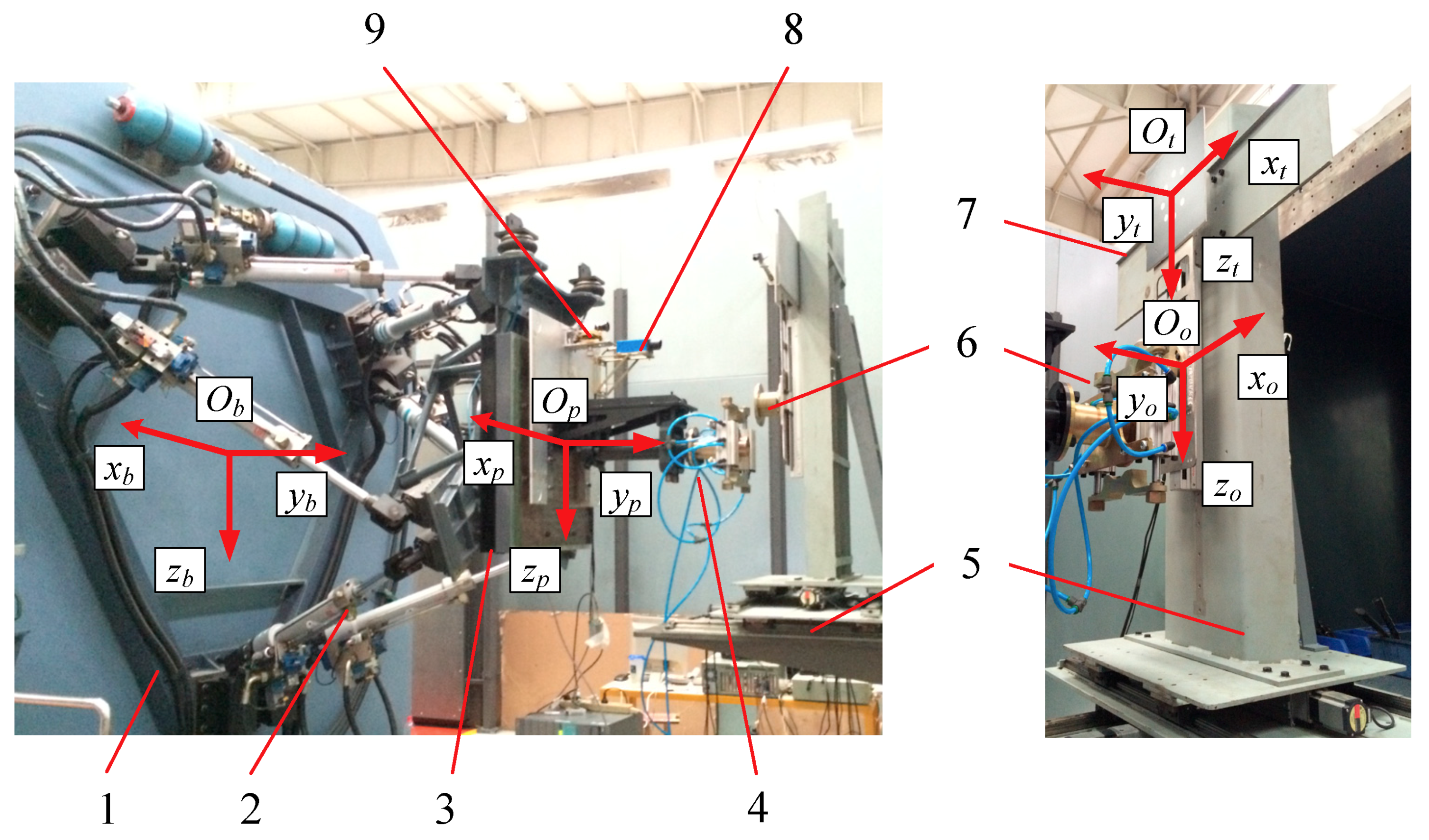
At present, we do not have the conditions for direct field experiments, so we designed a simulation experiment system to verify the feasibility of the scheme. The experiment system was designed to simulate the rocket propellant loading process under the influence of wind, as shown in Figure 2. Located in the middle of Figure 2 is the automated umbilical system, mainly including a hydraulic parallel platform (HPM) and a docking device as the end-effector. The fixed platform of the parallel mechanism is connected to the basement, which should be the rocket launch tower during the actual filling process. The moving platform on the right side is equipped with a docking device to realize the docking and locking function with the rocket refueling port. A 6-dof force sensor is located between the dynamic platform and the docking device to measure the contact force during the docking process. A monocular camera and a laser rangefinder are mounted on top of the moving platform to locate the fuel filler as the target object.
Located on the right side of Figure 2 is a simulation device for rocket body motion, with a target object installed in its middle corresponding to the fuel filling port in the real propellant filling process. The motion simulator device has slideways in x, y, and z directions, and simultaneous motion in all three directions can be achieved by stepper motors to simulate the rocket’s oscillation under the influence of wind.

2.2. Vision Positioning Method

Computer vision technology has been widely used in industry, medicine, aerospace, agriculture, and other fields because of its noncontact, low-cost, and easy-to-implement advantages [12]. According to the number of visual sensors employed, the visual servo system can be divided into monocular vision, binocular vision, and multieye visual positioning [13]. In this article, the novel automated umbilical system uses a fusion of monocular vision and laser rangefinder to locate the rocket fuel port and guide the parallel mechanism to approach the target object.
As shown in Figure 3, the image acquisition module first collects the target video image input by the camera in real time and the target detection module quickly confirms the distance of the target by pattern matching; then the target center detection and orientation modules calculate the position and orientation of the target by image segmentation and target tracking according to the distance of the target; the target center estimation module calculates the target center’s position by bundle adjustment according to the location of the target element; the target orientation estimation module will calculate the main direction of the target according to the position of the direction element and outputs the rotation angle [13,14].
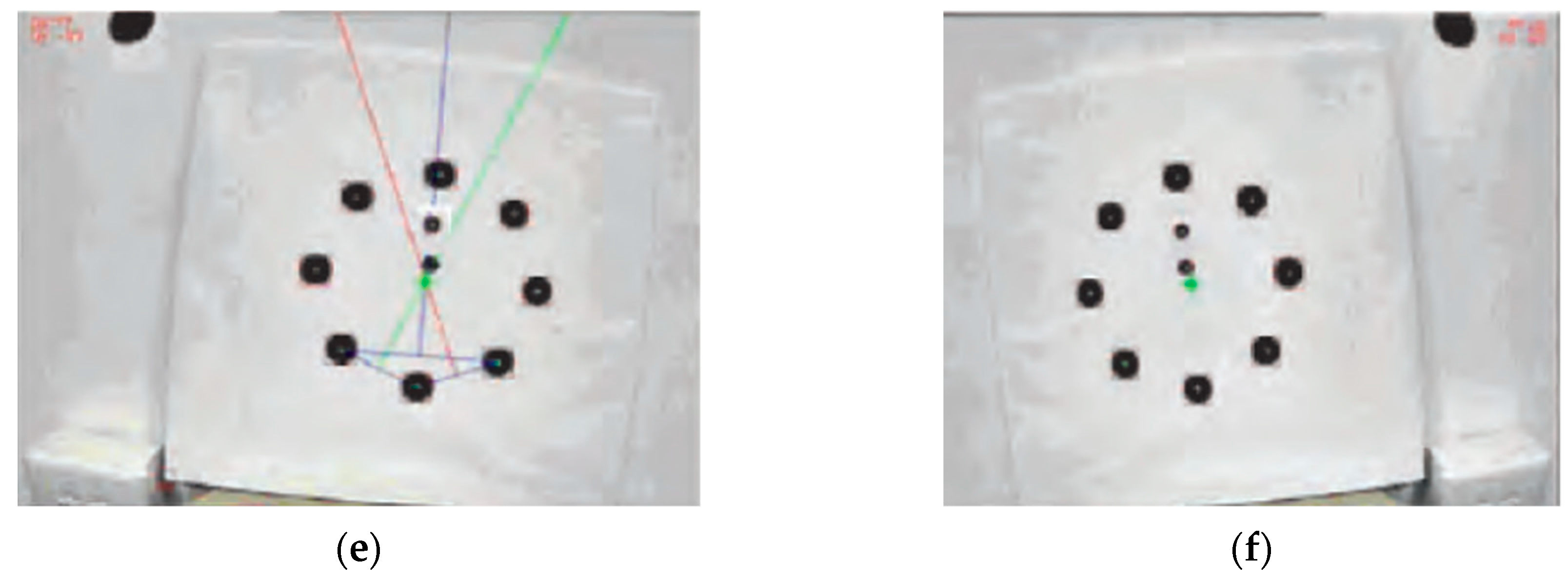
To identify the position and pose of the target, the target must first be accurately detected, the target and direction elements in the target must be accurately extracted, and then the key parameters must be estimated through robust statistics. Figure 4 shows the results of target image analysis.
As shown in Figure 4, (a) is the original target image; (b) is the binary image; (c) is the target detection result; (d) is the target detection result; (e) is the bulls eye estimation result, and the target position is marked by a green cross; and (f) is the estimated result of the main direction of the target.
Through the target image analysis, the position deviation of the camera axis relative to the target center (xd, yd), and the roll angle γ of the target in the camera image plane can be accurately identified.
Due to its own structure limitation, the measurement accuracy of monocular vision in the camera’s optical axis direction is relatively low, the manipulator cannot accurately perceive depth information. In this paper, the three laser-ranging sensors measure the distance between the camera and the target separately, estimate the inclination along the line of sight of the camera by analyzing the distance difference, and output the pitch angle β and the azimuth angle α.
As shown in Figure 2, by applying a laser rangefinder, the distance acquisition module measures the depth of the target and inclination estimation module estimates the tilt of the target by analyzing the deviation of the laser-ranging sensor. At last, the pose estimation module integrates the data collected by the camera and the laser rangefinder to estimate the position and orientation of the target.
A complete description of the relative position of the camera and the target requires six parameters: the position of the camera’s optical center on the three axes of the target coordinate system (x, y, z) and the inclination of the camera’s optical axis around the three axes (α, β, γ). Based on the distance Zd from the camera’s optical center to the intersection of the target surfaces, the coordinates of the camera’s optical center in the target coordinate system (xc, yc, zc) can be obtained by a simple calculation [12]:
x c = z d · sin α · cos γ + z d · sin β · sin γ
y c = z d · sin α · sin γ + z d · sin β · cos γ
z c = z d · cos α · cos β
Using the position deviation identified by the vision system (xc, yc) to modify these data, the correct position of the camera within the target coordinate system can be expressed as
x = x d z c f x c
y = y d z c f y c
z = z c
The vision system can only measure the relative position between the target object and the camera, the precise target’s location relative to the basement coordinate cannot be obtained directly. Since the camera is located at a fixed position on the platform, we can transform the position information according to the relative relationship between the various coordinate systems [14].
Here are the descriptions of the various coordinate systems involved: the basement coordinate system {B} of the parallel mechanism is O B X B Y B Z B , the eye-in-hand camera coordinate system {C} is O C X C Y C Z C , the moving platform coordinate system {P} is O P X P Y P Z P , and the vision target coordinate system is O t X t Y t Z t , the docking target object coordinate system is O o X o Y o Z o   , as shown in Figure 2.
The end-effector and the planar target are both installed at a fixed position of the docking experiment system, and the position relationship between the moving platform and the basement can be calculated by kinematics. Therefore, the position relationship between the target object coordinate and the basement can be derived as
T o B = T P B · T C P · T t C · T o t
where T o B represents the coordinate transformation matrix between the basement and the target object, T P B represents the coordinate transformation matrix between the basement and the moving platform, T c P represents the coordinate transformation matrix between the moving platform and the camera, T t c represents the coordinate transformation matrix between the camera and the planar target, and T o t represents the coordinate transformation matrix between the planar target and the docking device.
X o B = T o B · X o o = T P B · T c p · T t c · T o t · X o o
where X o B represents the target object’s position vector in the basement coordinate system {B} and X o o represents the docking device’s position in the target object coordinate system.
The end-effector’s position vector X e P in the moving platform coordinate {P} is known according to the design, so the end-effector’s position vector X e B in the basement coordinate {B} can be expressed as
X e B = T P B · X e P
Thus, the position deviation vector Δ X B of the end effector and the target object in the basement coordinate can be derived as
Δ X B = X o B X e B = T P B · T c p · T t c · T o t · X o o T t B · X e t

2.3. Manipulator Modeling

The main structure of the automated umbilical system adopts a 6-dof parallel mechanism, which has higher precision, faster response, and higher load-bearing capacity than traditional tandem robots with parallel structure. The six degrees of freedom of motion enable it to achieve precise tracking of the rocket in the working space without generating large contact forces on the rocket due to its own structural limitations [15].
Manipulator’s kinematics is a theory that describes the motion of the manipulator without considering the mass or the forces affecting the motion [16]. The kinematics of the parallel manipulator can be classified into inverse kinematics and forward kinematics. The inverse kinematics is a mathematical process of calculating the actuator parameters based on the given manipulator’s position and orientation [17]. Using an analytical method, the actuator length can be derived as
l = R l ( q ) · A + c B
where l R 6 indicates the actuator length vector from upper joints to lower joints, A R 3 × 6 and B R 3 × 6 are the moving platform and basement joint points matrix, respectively, R l R 6 × 6 is the rotation matrix from moving platform coordinates {P} to basement coordinate {B}, c R 3 is the position vector of the moving platform, and q R 6 is the state vector of the platform generalized coordinate.
The relationship [18] between the generalized velocity vector q ˙ and the actuator velocity vector l ˙ can be formulated as
l ˙ = J l q ( q ) q ˙
The forward kinematic concerns the end effector’s states with the given actuator’s length in the basement coordinate system {B}. In practical application, the Newton–Raphson method is used to estimate the manipulator’s status, thus the forward kinematics of parallel manipulator can be expressed as
q j + 1 = q j + J ( q j ) 1 ( l o l j )
where j is the interaction number, q j R 6 is the state vector of the platform coordinate, l j R 6 is the solving actuator vector during the jth iterative calculation, and l o R 6 × 1 is the initial measured actuator length vector. J ( q n ) R 6 × 6 is the Jacobian matrix that relates the body coordinate and the actuator velocity.
The dynamic equations of parallel robots can be deduced by various methods. In this paper, the Kane method [19] is used to describe the dynamic model of the parallel mechanism.
M ( q ) q ¨ + C ( q , q ˙ ) q ˙ + G ( q ) = J l q ( q ) T f + F e
where q R 6 is the manipulator’s position vector, M ( q ) R 6 × 6 is the mass matrix, C ( q , q ˙ ) R 6 is a matrix of centrifugal and Coriolis terms, G ( q ) R 6 × 6 is a vector of the gravity term, f R 6 is a 6 × 1 vector of actuator force, J l q R 6 × 6 is the parallel manipulator’s Jacobin matrix, and F e R 6 is a vector of generalized contact force.

3. Hydraulic System Control Scheme

3.1. Hydraulic System Modeling

Compared with the usual motor drive system, the hydraulic system has a higher power output ratio [20]. This means that the hydraulic system can output higher power under the same volume and weight. In rocket propellant filling work, we hope that the automated docking system can carry a higher weight in a limited working space, so the automated umbilical system chooses a hydraulic actuator to drive it.
However, the hydraulic actuator also has some shortcomings due to its own structural characteristics. For example, the lower frequency response compared to the motor drive system and the nonlinear flow rate generated by the servo valve will be analyzed later [21].
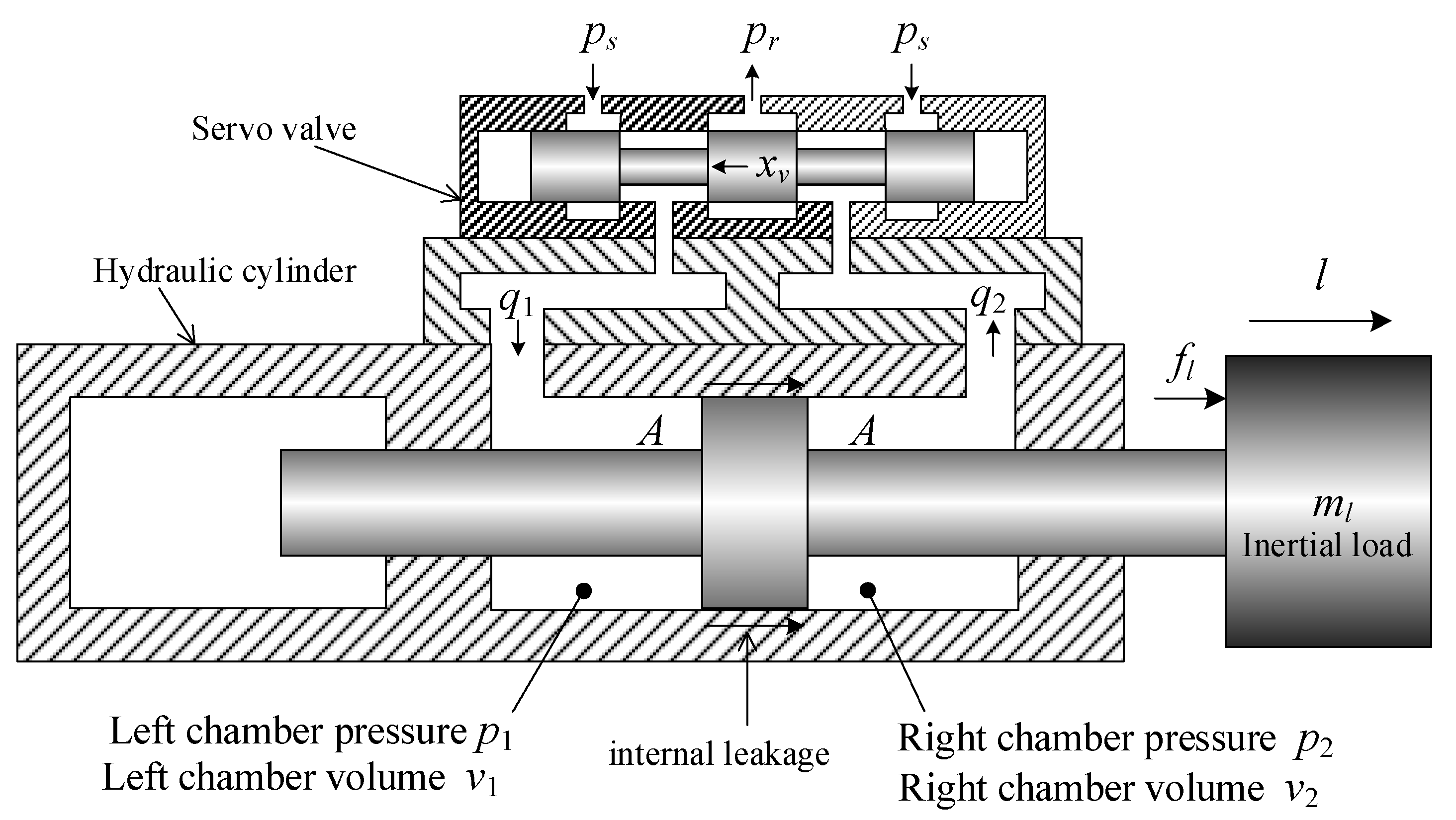
The electrohydraulic servo system is mainly composed of the electrohydraulic servo valve, hydraulic cylinder, displacement sensor, pressure sensor, and inertia load. The single rod asymmetric hydraulic cylinder can effectively reduce the length of the actuator and make the structure compact, which is conducive to improving the stiffness of the system. The performance parameters of the hydraulic cylinders are listed in Table 1.
The control system of the asymmetric cylinder is shown in Figure 5, where xv is the servo valve spool displacement and y is the hydraulic cylinder piston rod displacement.
According to the throttling flow formula [22], the flow rate into the left chamber of the hydraulic cylinder is
q 1 = { C d w x v 2 ρ ( p s p 1 ) x v 0 C d w x v 2 ρ ( p 1 p r ) x v < 0
The flow rate into the right chamber of the hydraulic cylinder is
q 2 = { C d w x v 2 ρ ( p 2 p r ) x v 0 C d w x v 2 ρ ( p s p 2 ) x v < 0
where q1 and q2 are the flow rates of the left and right chambers of the hydraulic cylinder, respectively, p1 and p2 are the pressures of the left and right chambers of the hydraulic cylinder, respectively, ps is the oil source pressure, pr is the hydraulic line pressure, Cd is the flow rate coefficient, w is the throttle area gradient, xv is the servo valve spool displacement, and ρ is the hydraulic oil density.
The flow continuity equation for the left chamber of the hydraulic cylinder is
q 1 = A 1 l ˙ + v 1 β e p ˙ 1 + c i c ( p 1 p 2 ) + c e c p 1
The flow continuity equation for the right chamber of the hydraulic cylinder is
q 2 = A 2 l ˙ v 2 β e p ˙ 2 + c i c ( p 1 p 2 ) c e c p 2
where A1 and A2 are piston effective area of the left and right chambers; l is piston rod displacement; v1 and v2 are the volumes of the left and right chambers, respectively; cic and cre are the internal leakage coefficient and external leakage coefficient of the hydraulic cylinder, respectively.
The hydraulic system force balance equation is
f l = A 1 ( p 1 p 2 ) = m l l ¨
Define the load flow q L = 1 2 ( q 1 + q 2 ) , load pressure p L = p 1 p 2 , considering p s = p 1 + p 2 and p r = 0 , we can add Equations (15) and (16) to obtain the load flow
q L = C d w x v p s sign ( x v ) p L ρ
When the hydraulic cylinder moves near the neutral position, it can be approximated as v1 = v2, and we can add Equations (17) and (18) to obtain
q L = A l ˙ + V t 4 β e p ˙ L + c t c p L
where c t c = c i c + 0.5 c e c is total hydraulic cylinder leakage coefficient and Vt is the total volume of the two chambers of the hydraulic cylinder.
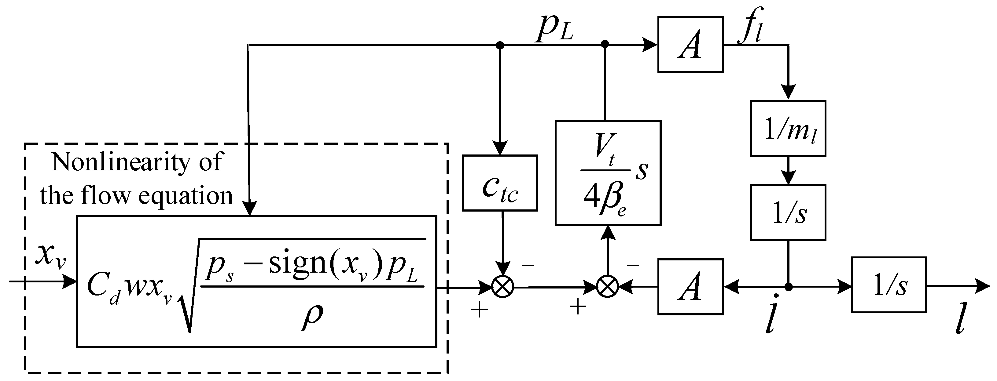
According to Equations (19)–(21), the nonlinear model of the electrohydraulic servo system is represented as the block diagram shown in Figure 6. The nonlinear part mainly considers the nonlinear influence of the servo valve flow equation.

3.2. Hydraulic System Nonlinear Compensation

There are many nonlinear factors in the electrohydraulic servo system [23], including the dead zone of the servo valve, hysteresis, the Coulomb friction of the hydraulic actuator, etc. The main consideration in this article is the nonlinear effect of the flow equation of the servo valve. When the load changes make the steady-state operating point of the system deviate from zero, the nonlinearity of the flow equation will cause the valve flow coefficient to be different during forward and reverse movement, resulting in the problem of asymmetric movement.
It can be seen from Equation (21) that the load flow rate is not proportional to the spool displacement, and the load flow rate is a nonlinear function of two variables, the spool displacement and the load pressure.
In order to have a linear proportional relationship between the load flow and the spool displacement, a nonlinear compensation function h(pL) is introduced before the nonlinear model shown in Figure 6. After the hydraulic system undergoes nonlinear flow compensation, it can linearize the flow nonlinearity equation. The nonlinear compensation method is shown in Figure 7.
In this case, the spool displacement of the servo valve is
x v * = h ( p L ) x v
where x v * is the spool displacement after nonlinear flow compensation.
We define the flow nonlinear compensation function h(pL) as
h ( p L ) = p s p s sign ( x v ) p L
This nonlinear compensation function is related to the load pressure. The load pressure pL can be measured by a pressure sensor. The servo valve flow rate after nonlinear flow compensation is:
q L = C d w x v * p s sign ( x v * ) p L ρ = C d w x v p s ρ
Comparing Equation (24) with Equations (17), (20) and (21), it can be seen that there is a linear relationship between the compensated servo valve flow rate and the spool displacement.
When the moving direction of the hydraulic system changes, the flow gain will change abruptly due to the nonlinearity of the servo valve [24], making the acceleration feedback signal distorted, and this phenomenon is more obvious when the frequency is low. When the frequency is higher, the acceleration is larger, the inertial force gradually plays a dominant role, and the acceleration distortion phenomenon will be relatively weakened. After adopting the flow nonlinear compensation strategy, the flow gain is independent of the load pressure and can be regarded as a constant, and there is no obvious distortion in the feedback signal of acceleration for either low- or high-frequency motion. In the actual electrohydraulic servo system, in addition to the flow nonlinearity, other nonlinearities of the hydraulic system, such as magnetic loops, dead zones, and Coulomb friction, also have adverse effects on the system, so the actual system will still have some acceleration distortion after using the flow nonlinearity compensation.
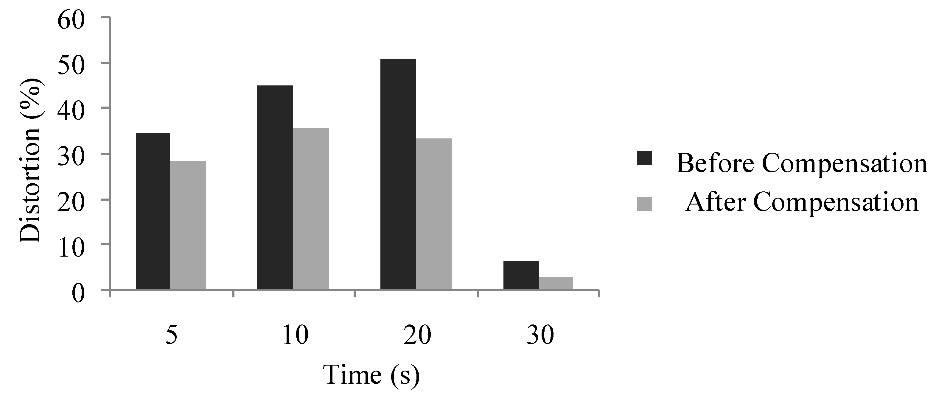
Because of the effect of servo valve nonlinearity, the hydraulic system has a large signal tracking error for acceleration. As shown in Figure 8, the hydraulic system tracks sinusoidal signals with frequencies of 5, 10, 20, and 30 Hz, and the tracking curves of acceleration are compared. From Figure 9, it can be seen that the nonlinear compensation can effectively reduce the tracking distortion of the hydraulic system for the acceleration signal. Furthermore, as the signal frequency increases, the compensation effect is more obvious.

3.3. Three-State Feedback Control

From Equations (19) and (22) to Equation (24), the open-loop transfer function of the single-degree-of-freedom electrohydraulic displacement servo control system can be obtained as
L U = k s h s ( s 2 ω h 2 + 2 ζ h ω h s + 1 )
where the system open-loop gain k s h = k s v k q / A , ω h is the hydraulic servo system inherent frequency, and ζ h is the hydraulic servo system damping ratio.
The inherent frequency ω h and damping ratio ζ h of the hydraulic servo system are expressed as
ω h = 4 β e A 2 V t m l
ζ h = k c e A β e m l V t
where k c e = k c + c t c is the total flow pressure coefficient.
Typically, hydraulic damping ratios of 0.15 to 0.3 are difficult for an uncorrected electrohydraulic servo system using only proportional link control to make the system wider than ω h . Common methods for improving the damping ratio in the design of the physical structure of hydraulic systems include the use of positive opening valves, bypass leakage, and increasing the viscous damping of the load [25].
In this paper, a three-state feedback control strategy is used to adjust the system parameters. The three states refer to the displacement, velocity, and acceleration of the hydraulic cylinder piston. There are more design methods for three-state feedback control, such as using the root locus method [26] and the pole-placement method [27] to design the feedback controller. In this section, the three-state control strategy of the electrohydraulic servo system is designed based on the state feedback in the state space.
The state variable g of the electrohydraulic servo system can be expressed as
g = [ l l ˙ l ¨ ] T
According to Equations (25)–(27), the equation of state of the system can be expressed as
{ g ˙ 1 = g 2 g ˙ 2 = g 3 g ˙ 3 = ω h 2 k s h u ω h 2 g 2 2 ζ h ω h g 3
Converting Equation (29) into the form of a matrix differential equation gives
g ˙ = A g + B u
A = [ 0 1 0 0 0 1 0 ω h 2 2 ζ h ω h ]
B = [ 0 0 ω h 2 k s h ] T
Obviously, since the coefficient matrices A and B of the state equations belong to the standard controllable matrices, arbitrary configurations of the poles can be achieved through state feedback.
The output equation of the system is
l = C g g
C g = [ 1 0 0 ]
The state feedback matrix of the system can be expressed as
K f = [ k d f k v f k a f ]
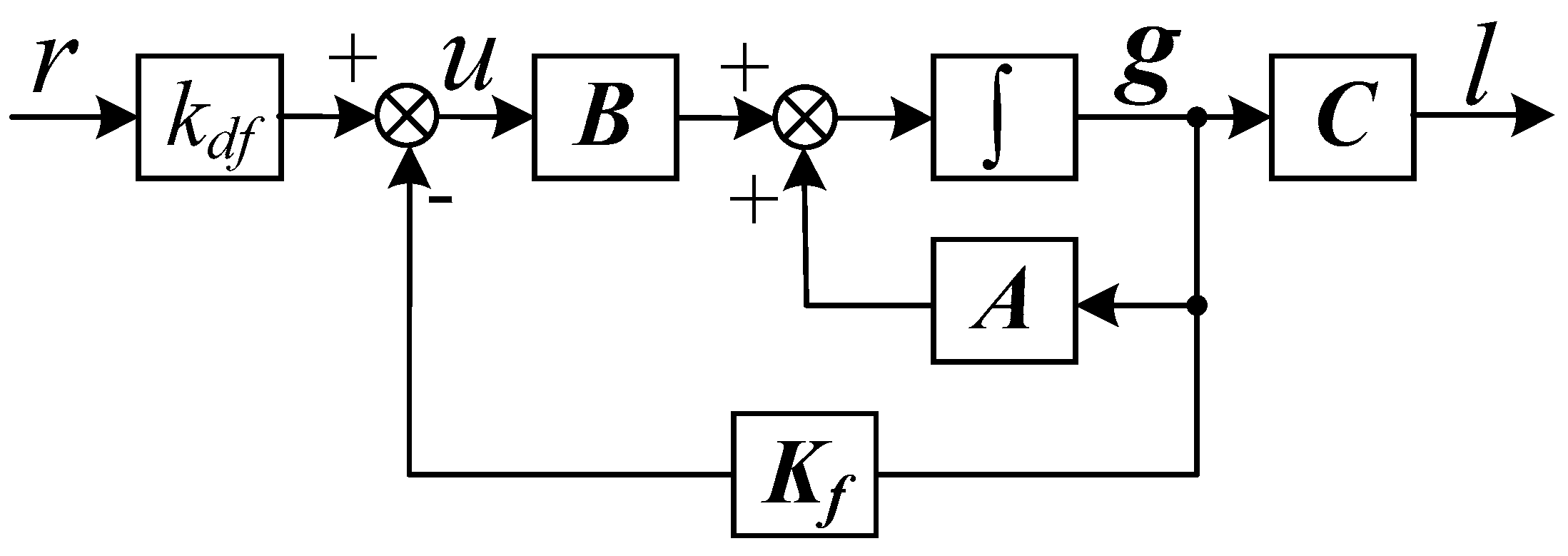
After three-state feedback adjustment, the system can be represented as a block diagram, as shown in Figure 10.
The state equation of the adjusted system is
u = k d f r K f g
g ˙ = ( A B K f ) g + B k d f r
After the state feedback modification, the coefficient matrix of the state equation is
A B K f = [ 0 1 0 0 0 1 k d f k s h ω h 2 ω h 2 k v f k s h ω h 2 2 ζ h ω h k a f k s h ω h 2 ]
The characteristic equation of the coefficient matrix is
| s I ( A B K f ) | = | s 1 0 0 s 1 k d f k s h ω h 2 ω h 2 + k v f k s h ω h 2 s + 2 ζ h ω h + k a f k s h ω h 2 | = s 3 + ( 2 ζ h ω h + k a f k s h ω h 2 ) s 2 + ( ω h 2 + k v f k s h ω h 2 ) s + k d f k s h ω h 2
According to the characteristic equation, after three-state feedback, the stable condition of the system is:
( 2 ζ h ω h + k a f k s h ω h 2 ) ( ω h 2 + k v f k s h ω h 2 ) > k d f k s h ω h 2
In order to make the three-state feedback system have better dynamic characteristics, the closed-loop amplitude–frequency characteristics need to be close to one in the widest possible frequency band. It is easy to prove that for a third-order system, such an ideal closed-loop transfer function should have the following typical form [28]:
G 3 ( s ) = 1 s 3 ω n c 3 + 2 s 2 ω n c 2 + 2 s ω n c + 1
where ω n c is the integrated frequency of the ideal third-order transfer function.
The characteristic equation of this equation is
s 3 + 2 ω n c s 2 + 2 ω n c 2 s + ω n c 3 = 0
Comparing with Equation (39), the following relationship is obtained:
{ 2 ω n c = 2 ζ h ω h + k a f k s h ω h 2 2 ω n c 2 = ω h 2 + k v f k s h ω h 2 ω n c 3 = k d f k s h ω h 2
Although the electrohydraulic servo system with three-state feedback can theoretically achieve any configuration of poles, the actual system’s inherent frequency and damping ratio cannot be increased indefinitely, and are limited by the dynamic characteristics of the servo amplifier, servo valve, and sensors. The difference between the inherent frequency of the servo valve and the inherent frequency of the dynamic mechanism determines the magnitude of the inherent frequency and damping ratio that can be increased by the three-state feedback.
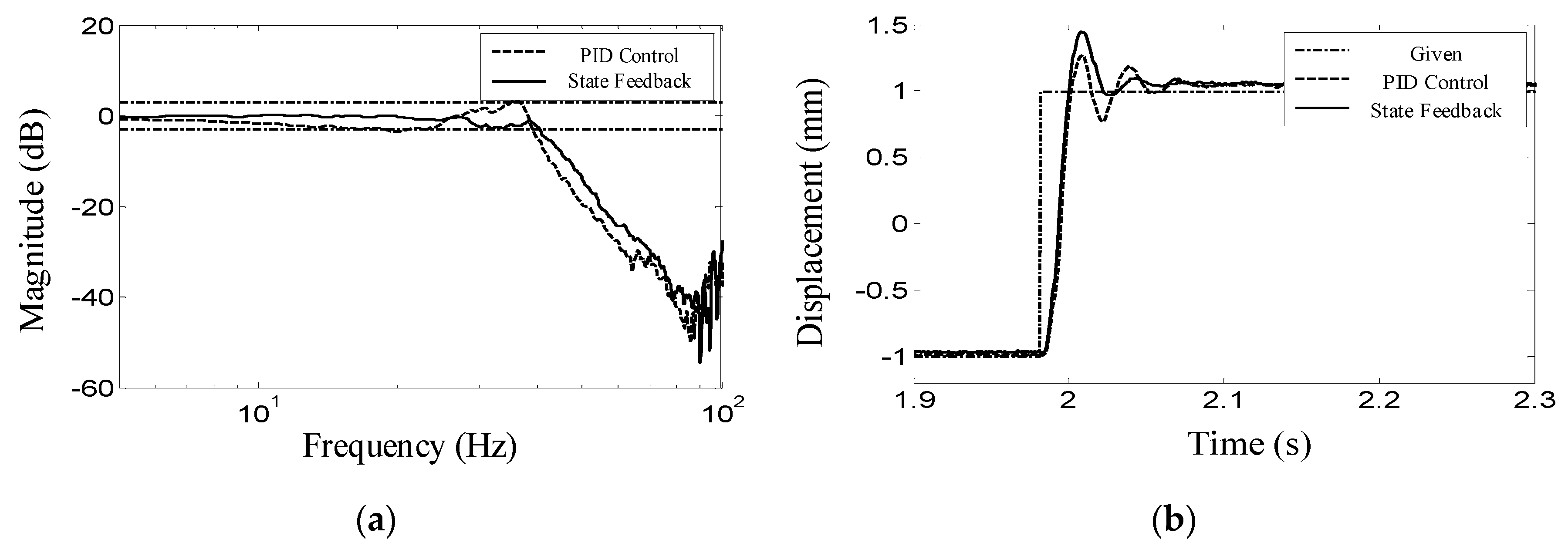
Figure 11 shows the closed-loop frequency characteristics and step response under PID control and three-state feedback control, respectively. It should be noted that after the three-state feedback, there is no obvious resonance peak at the intrinsic frequency of the servo valve, and the bandwidth of the system is further improved. From the step response waveform, it can be seen that the number of oscillations of the system becomes less after using the three-state feedback, which means that the damping ratio of the system becomes larger under the three-state feedback.

4. Force Tracking Control Scheme

According to the working requirements of the rocket umbilical docking system, when docking with the rocket analog interface or following its movement, contact force will be generated at the interface; at this time the simple position control cannot guarantee the requirements of the contact force, and the force controller must be designed to realize the control of the contact force during the movement to make it meet the requirements. Aiming at this problem, an adaptive impedance control algorithm based on an online environment estimation is proposed to achieve compliance control during and following contact [29].

4.1. Analysis and Design of Impedance Controller

When performing a task with an impedance control strategy, the robot adjusts the impedance controller parameters to achieve stable contact and desired force control based on the relationship between the end position and the force [30]. In practical engineering applications, the impedance relationship between the robot end and position deviation is generally established in the form of a second-order differential equation with the mathematical expression of the desired impedance model:
M d ( X X d ) + B d ( X X d ) + K d ( X X d ) = F e
where M d , B d , K d are the desired inertia matrix, damping matrix, and stiffness matrix; X , X ˙ , X ¨ are position, velocity, and acceleration vectors of the robot end-effector; R d is the desired trajectory of robot end-effector; and F e is the robot and environment contact force vector.
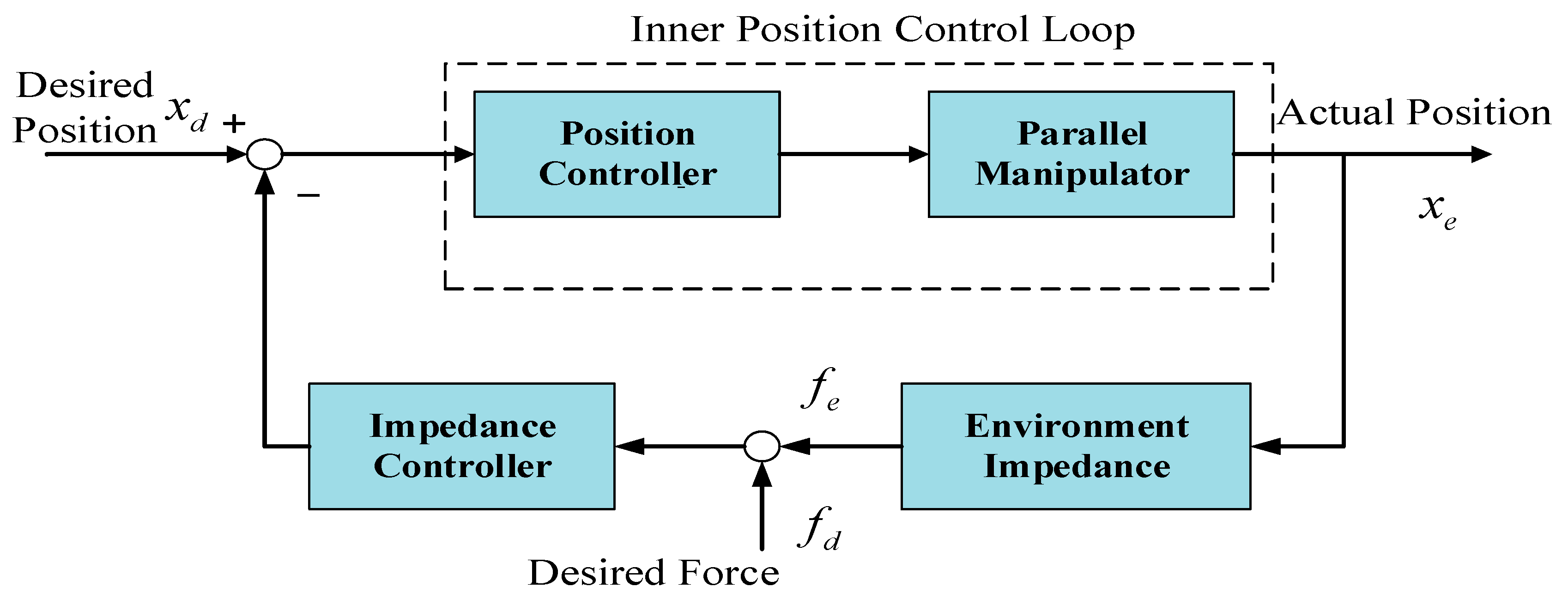
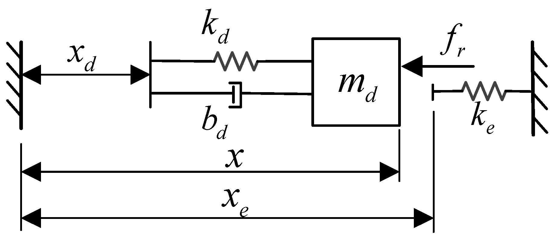
As shown in Figure 12, to enable force tracking, the desired contact force and the actual contact force error signal E = F d F e can be used as the driving force of the desired impedance model, so the expression of the new desired impedance model is
M d ( X X d ) + B d ( X X d ) + K d ( X X d ) = E
In Cartesian coordinates, the mass, damping, and stiffness matrices are generally in the form of diagonal matrices for low frequency kinematic systems if modal space coupling is not considered. In order to reduce the difficulty of analysis, we can use one-dimensional variables f d , f e , m d , b d , k d to replace the multidimensional variables F d , F e , M d , B d , K d when analyzing a single-degree-of-freedom model.
The impedance model can be represented as a mass–spring–damping system. In free motion, the robot is an independent controlled object; when in contact with the environment, it can be seen as an integrated dynamic system consisting of the robot end and the external environment. At this point, the environmental dynamics model needs to be considered, considering only the environmental stiffness factor, and its dynamics model is
f e = k e ( x x e )
When the environmental damping factor is considered, the dynamics is modeled as
f e = b e x . + k e ( x x e )

4.2. Stability Analysis of Impedance Control

A block diagram of a single degree of freedom transfer function based on impedance control is shown in Figure 12. It consists of two loops: the position inner loop servo control and the force outer loop based on impedance control.
This impedance-based control system is not only to design the structural form of the impedance control model, but also to make reasonable adjustments to the parameters of the target impedance model to ensure stable contact with the external environment, and the control performance of the contact force.
The environment is deformed by contact with the robot end effector, and the linearized relationship between force and motion established at the point of contact can be described as
f = m e p ¨ + c e p ˙ + k e
where p = x x e is the actual deformation of the robot end in contact with the environment, x e is the position of the contact point, m e , c e , and k e are the inertia, damping, and stiffness of the environment, respectively.
The key to impedance control is to maintain the relationship between contact force and position error. Taking into account the multiple degrees of freedom of the robot, the impedance controller can be expressed as
F = M d e ¨ + B d e ˙ + K d
where   e = x d x   is the position error; and M d , B d , and K d are the inertia matrix, damping matrix, and stiffness matrix of the impedance model, respectively.
From this equation, the end-effector displacement after contact occurs can be expressed as
X = G p ( s ) X d + G d ( s ) 1 F
Substituting Equation (49) into Equation (50) we obtain
F ( s ) = [ G d ( s ) 1 + G e ( s ) 1 ] 1 G p ( s ) p 0 ( s ) = Z C ( s ) p 0 ( s )
For how to define the necessary and sufficient conditions for impedance control under stable force/position tracking, scholars agree with the following statements [31]. In fact, if the robot does not break away from the environment during the process of contact with the environment, it can be considered that the process of overcontact is stable. A stable contact process should be at the end of the robot so that the deformation of the environment is always positive, and there should be no large jumps. The most critical issue is the rigid collision between the robot end and the environment. The controller should ensure that the end of the robot stays in contact with the environment from the beginning of the collision contact until the collision kinetic energy is completely absorbed.
Assuming that the actual deformation of the environment p is always positive (compression is positive), it can be expressed as
| x ( t ; t 0 , x t 0 ) | > | x e |
where the end effector is always in contact with the environment when t t 0 . At time t 0 , the end-effector begins to come into contact with the environment, x t 0 = x e . It can also be equivalently expressed that there is always a contact force F ( t ) 0 in the direction of contact.
We can use this stability criterion to calculate the conditions that the system parameters should satisfy when the impedance control is stable. The environmental deformation p should always be positive during the contact action, then the corresponding impedance transfer function is a positive real transfer function. The positive real transfer function can describe the behavior of the passive mechanical system, that is, the force that keeps the system in stable contact is always applied by the external environment. In addition to this, to obtain a relatively simple impedance control transfer function, the position servo system is assumed to be ideal, G P = I . Since both the target impedance transfer function and the environmental dynamics transfer function are assumed to be Hurwitz polynomials, the necessary conditions for contact stability in the constrained direction can be expressed as
R e { G d ( s ) / [ G d ( s ) + G e ( s ) ] } 0                         s = j ω , ω [ 0 , ]
From these equations, it can be concluded that the impedance control system should satisfy the following parameters when it is stable:
{ ζ d = b d 2 m d k d κ = k e k d ξ d 0.5 ( 1 + κ 1 )

4.3. Force Tracking Error Analysis

The collision dynamics model of the robot end in contact with the environment is shown in Figure 13. The variable x and x d denote the actual trajectory and desired trajectory of the robot end, respectively, f denotes the actual contact force, and the environmental dynamics model is simplified to a linear spring, so the contact force can be simply expressed as
f = { k e ( x x e ) ( x x e ) 0 ( x < x e )
where k e is equivalent stiffness of environmental and end-effector force sensors, and x e is the environmental position when no deformation occurs.
Setting the force error e = f r f e , it can be derived from the environmental dynamics model that
x = f e k e + x e = 1 k e ( f r e ) + x e
In order to ensure that the expected force f is constant, the deformation of the environment by the expected trajectory must also be constant, so we have x ¨ d = x ˙ d = 0 . Substituting Equation (56) into the target impedance model of Equation (45), the differential equation of the force error is obtained
m d e + b e . + ( k d + k e ) = m d f r . . + b d f r . + k d f r k d k e ( x d x e )
Assuming that f r is a constant value, then f ¨ r = f ˙ r = 0 , the steady-state force error is
e s s = k d k d + k e [ f r + k e ( x e x d ) ] = k e q ( f r k e + x e x d )
The equivalent stiffness of control system and environment is
k e q = k d k e k d + k e
Then the steady-state contact force with the environment is
f s s = f r e s s = k e q ( f r k d + x d x e )
From Equation (60), the steady-state force error e s s is a function of the desired force f r and the desired position x d . Therefore, the ideal desired trajectory is
x d = f r k d + x e
At this time, the steady-state force error e s s is zero. It can be seen that if the environment position x e and stiffness k can be accurately known, then an accurate desired trajectory x d can be given according to Equation (61), so that the contact force f between the robot end and the environment can accurately track the desired force f r . According to Equation (60), the deformation caused by the interaction between the desired trajectory x d and the environment is f r k d , so as to ensure the desired contact force f r .
In fact, the environmental parameters x e and f e are generally unknown. Δ x e represents the difference between the actual and estimated environmental position, and Δ k e represents the difference between the actual and estimated stiffness, then we can derive that
Δ x e = x e x ˜ e Δ k e = k e k ˜ e
where x e and k e are actual values of environmental position and stiffness, and x ˜ e and k ˜ e are the estimates of environmental position and stiffness.
The steady-state force error at the desired position is obtained from the equation x d = x ˜ e + f r k ˜ e as
e s s = k d k d + k e ( k e Δ x e Δ k e k ˜ e f r )
The force steady-state error Equation (63) shows that it is difficult to accurately estimate the environmental position x e , resulting in the presence of Δ x e and because the environmental stiffness value k e is usually large, resulting in a large value of the steady-state force error e s s . This makes it inevitably difficult to ensure that the contact force between the robot and the environment stably tracks the given desired force.

4.4. Impedance Control Based on Online Estimation of Environmental Parameters

From the analysis above, it can be concluded that if the stiffness and deformation of the environment can be obtained, then impedance control can be well implemented to track the specific force; however, the parameters of the environment are often unknown and time-varying under actual working conditions [32]. In this section, we design an online estimation controller for environmental parameters based on the second method of Lyapunov stability theory. The second method is a criterion established from the energy point of view [33]. If the energy inside the system decays with time, it can be assumed that the system will reach the stationary state sooner or later, and the system is stable at that time.
This section focuses on estimating the environmental parameters k e and x e online in real time, and then solving the desired trajectory x d in real time. From the previous section, it can be seen that if k e and x e can be known precisely, the desired trajectory x d can be set as
x d = x e + f r k e
Since the displacement and deformation of the environment cannot be measured directly, the desired trajectory xd can be set as
x d = x ˜ e + f r k ˜ e
where x ˜ e and k ˜ e are the estimated values of x e and k e , respectively.
The following relationship can be derived from Equation (55):
f = k e ( x x e ) = k e x k x
f ˜ = k ˜ e ( x x ˜ e ) = k ˜ e x k ˜ x
where k ˜ x = k ˜ e x ˜ e is the estimated value of k x = k e x e , which can also be seen as a predicted displacement value based on the estimated parameters of the current environment.
Set the difference of the contact force as
f ˜ f = [ x     1 ] ϕ
The main goal is to design a control strategy that can make f ˜ converge to f when time t tends to infinity by continuously adjusting k ˜ e and k ˜ x based on the prediction force error f ˜ f . The following section derives the conditions to achieve f ˜ convergence to f .
According to Equations (55) and (65), the following can be derived:
f = k ˜ e ( x x ˜ e ) = k ˜ e ( x x d + f r k ˜ e ) = k ˜ e ( x d x ) + f r
Knowing from the target impedance, Equation (45), Equation (55) is used to eliminate ( x d x ) . In addition, note that if f ˜ = f , then k is a constant value, and we can get
m d e . . + b e . + ( k d + k ˜ e ) e = 0
Thus, if f ˜ f , then f f r or k ˜ e K . Obviously, the environmental stiffness value should be a positive value; the latter is not true. Therefore, it can be concluded that if f ˜ f , then f f r .
Therefore, in this paper, we develop a Lyapunov-based algorithm to update the estimated parameters k ˜ e and k ˜ x , thus the contact force f will eventually converge to f r . Define the Lyapunov function as
V = ϕ T Γ ϕ
where Γ is a second-order positive definite real symmetric matrix. We assume that ϕ can be written as
ϕ . = Γ 1 [       x 1 ] ( f ˜ f )
Then, from Equations (71) and (72), we obtain
V . = 2 ϕ T Γ ϕ . = 2 ϕ T [       x 1 ] ( f ˜ f ) = 2 ( f ˜ f ) 2
It is obvious that V · ( ϕ , t ) is negative semidefinite. If ϕ is adjusted according to Equation (72), when t , then from Equations (67) and (70) we can show that f f r . From the definition, it is clear that
ϕ = [ ϕ k ϕ x ] = [ k ˜ e k e k ˜ x k x ] = [ k ˜ e k e k ˜ e x ˜ e k e x e ]
ϕ . = [ k ˜ e . k ˜ e . x ˜ e + k ˜ e x ˜ e . ] = Γ 1 [ x 1 ] ( f ˜ f )
[ 1 / γ 1 0 0 1 / γ 2 ] [ k ˜ ˙ e k ˜ ˙ e x ˜ e + k ˜ e x ˜ ˙ e ] = [ x 1 ] ( f ˜ f )
Γ = [ 1 / γ 1 0 0 1 / γ 2 ]
The parameters γ 1 and γ 2 are positive real constants. From this analysis, it can be concluded that
k ˜ e . = γ 1 x ( f ˜ f )
x ˜ e . = ( f ˜ f ) k ˜ e ( γ 1 x x ˜ e + γ 2 )
Therefore, the force control algorithm based on online parameter estimation can be written as
x d = x ˜ e + f r k ˜ e
k ˜ e ( t ) = k ˜ e ( 0 ) γ 1 0 t x ( f ˜ f ) d t
x ˜ e ( t ) = x ˜ e ( 0 ) + γ 1 0 t ( f ˜ f ) k ˜ e ( x x ˜ e + γ 2 γ 1 ) d t
This is our design of adaptive impedance control based on the estimation of online environmental parameters using Lyapunov’s second method. The method above uses the parameters x ˜ e and k ˜ e derived from the online estimation to compute the desired trajectory xd by equivalently replacing the actual environmental parameters x e and k e . The previous analysis also demonstrates that when t , then f f r , x e and k e is independent of whether the parameters xe and k e are known.

4.5. Simulation of Force Control Based on Online Environmental Parameter Estimation

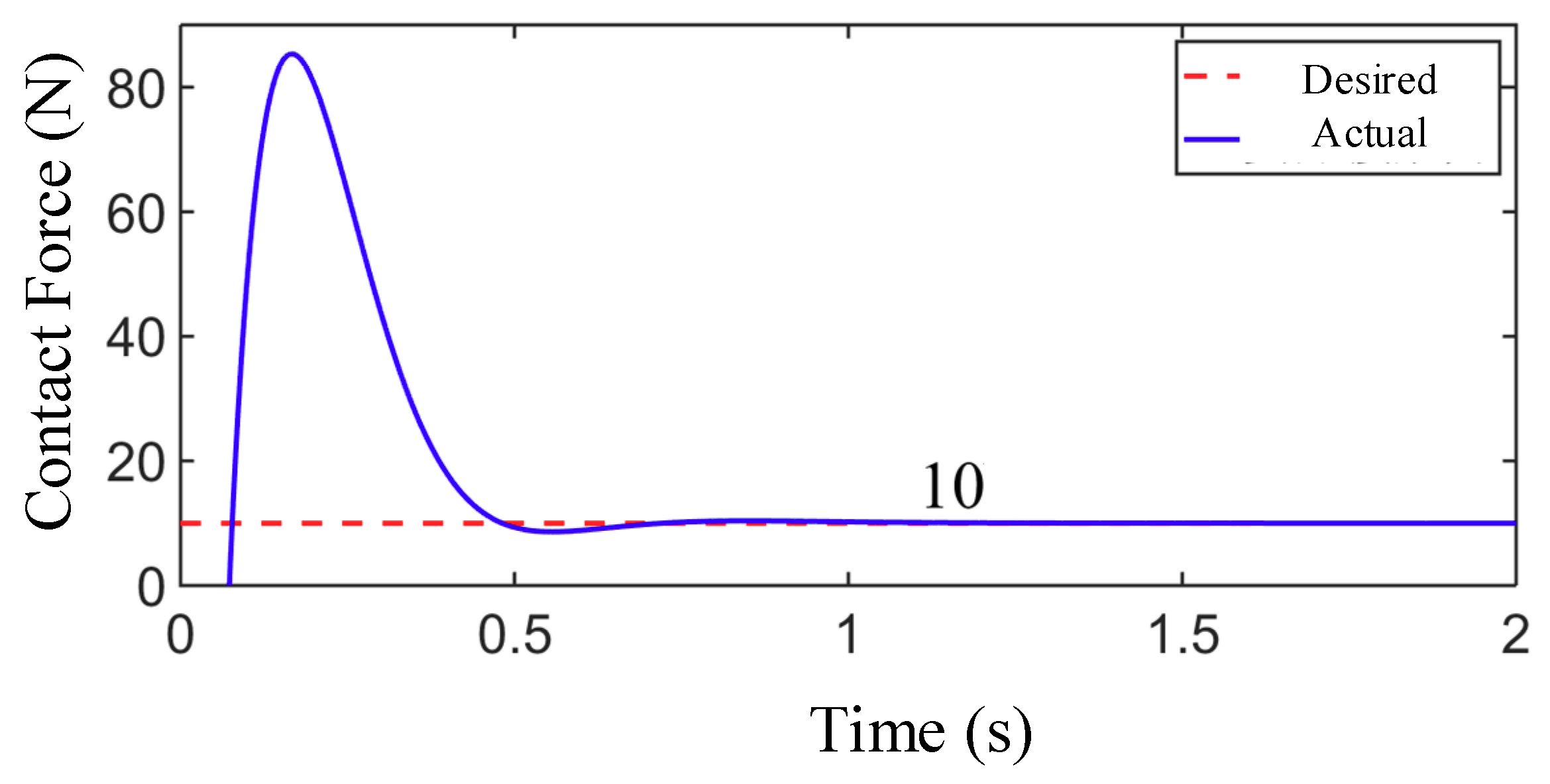
The simulation conditions are set to consider only the environmental stiffness in which the actual stiffness of the simulation environment is k e = 10,000 N/m, the actual position is xe = 0.05 m, and the desired contact force is fr = 10 N. The environmental parameters are initially estimated to be x ˜ e ( 0 ) = 0.048 m and k ˜ e ( 0 ) = 10,000 N/m, and the two controller parameters are γ 1 = 400 and γ 2 = 3.4 ; the results are shown in Figure 14.
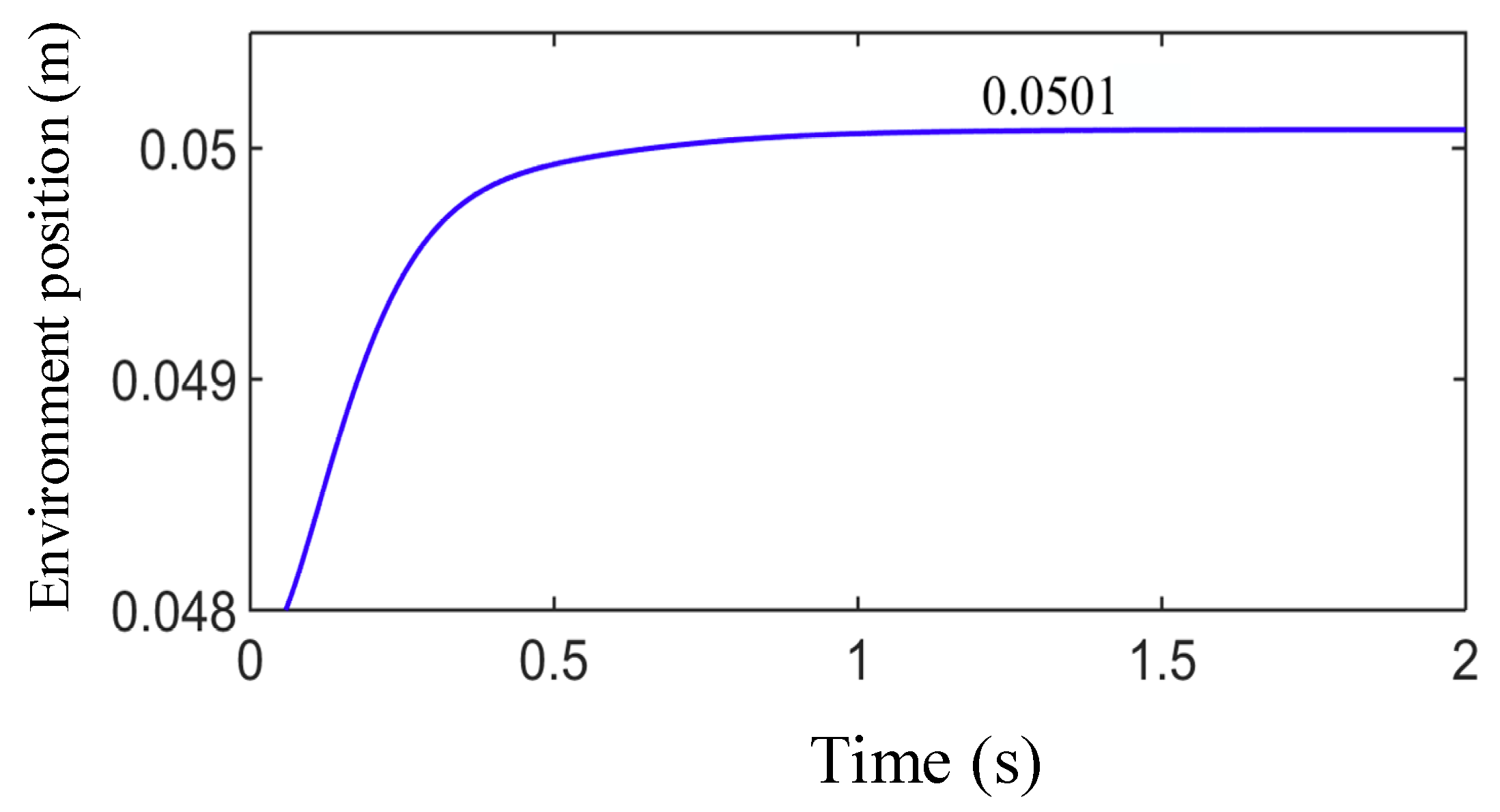
From Figure 15 and Figure 16, the estimated values of the environmental parameters at steady state of the system are
x ˜ e = 0.0501   m , k ˜ e = 10,891   N / m
It can be seen that although the expected contact force is well tracked, the results of online parameter estimation have a certain deviation from the actual parameters, which have a strong relationship with the initial value of the variable. The main reason is that we regard the convergence of the prediction deviation f ˜ f as the control objective. Therefore, this control strategy can approximate the desired trajectory when combining the environmental position and the stiffness parameter value.

4.6. Overall Control Loop

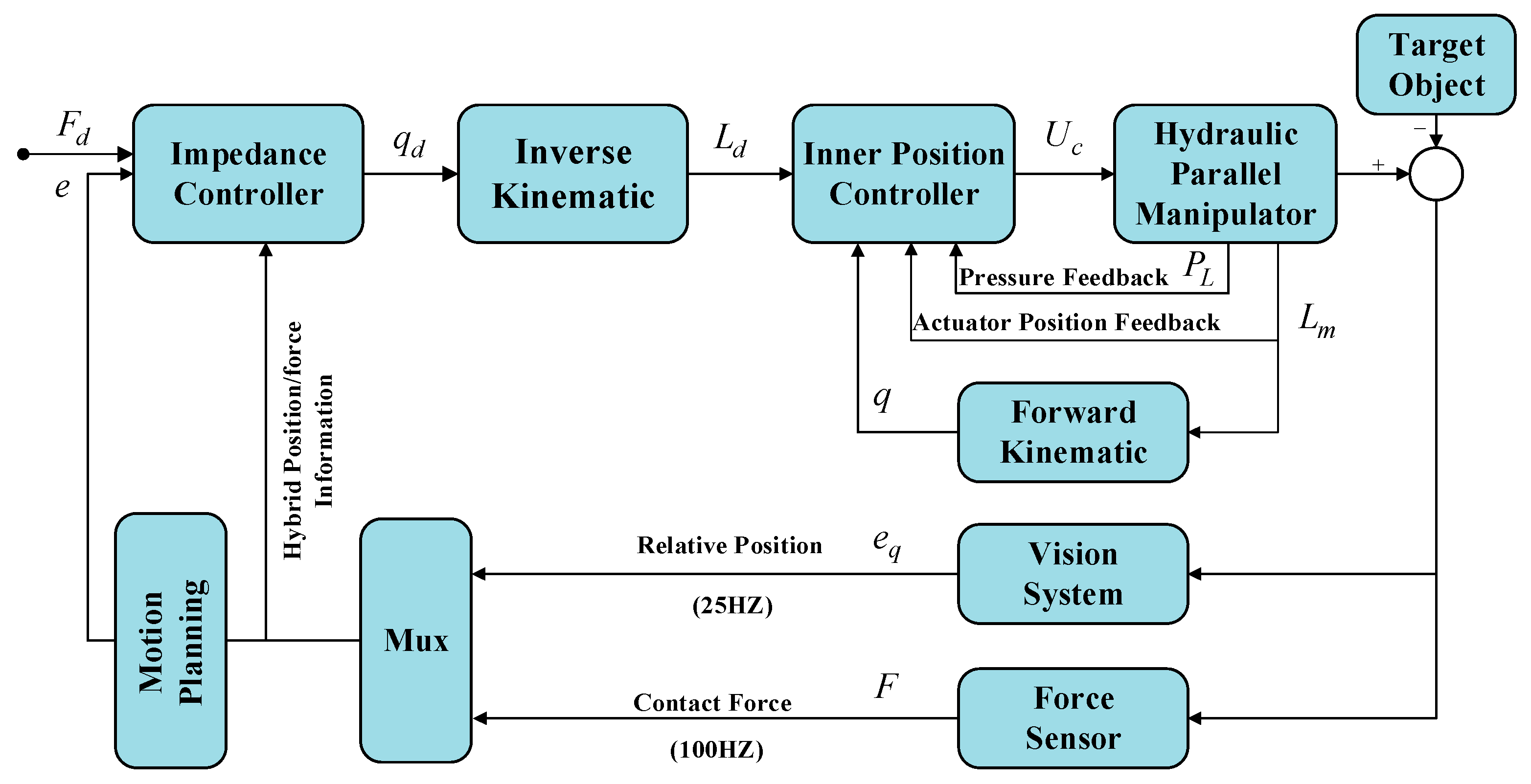
As shown in Figure 17, the entire control system consists of a position-controlled inner loop and force-controlled outer loop, wherein the inner loop is designed to ensure the system accuracy and rapidity of the system to track a specific movement with a high sample rate (500 Hz) linear variable differential transformer (LVDT); the outer control loop computes an appropriate trajectory to approach the target object based on the fusion of 6-dof force sensor (100 Hz) and vision sensor (25 Hz).
The entire experiment consists of four sections: approach process, docking and inserting process, tracking process and separate process. Throughout the entire experiment, the system controller calculates the reference trajectory of the parallel manipulator based on relative position feedback and interaction force information. As shown in Figure 17, the motion planning module is designed to plan the whole experiment process and calculate the manipulator’s path based on finite state machine theory.
To ensure the safety and reliability of the manipulator’s interacting process, the manipulator is designed to approach the target in a smooth trajectory. The constraint conditions are defined as
a .   position   constraint :   z ( t 0 ) = z 0 ,   z ( t 0 + Δ t ) = 0
b .   speed   constraint :   v ( t 0 ) = 0 ,   v ( t 0 + Δ t ) = 0
c .   acceleration   constraint :   a ( t 0 ) = 0 ,   a ( t 0 + Δ t ) = 0
where t0 is system initial time, Δ t is system control period, and z0 is the distance between the manipulator and the tracking target along z direction.
In this paper, the fifth-order polynomial interpolation is used to obtain the moving trajectory that meets the constraint requirement. The trajectory equation can be described as
z ( t ) = z 0 + 10 Δ t 3 ( 0 z 0 ) ( t t 0 ) 3 15 Δ t 4 ( 0 z 0 ) ( t t 0 ) 4 + 6 Δ t 5 ( 0 z 0 ) ( t t 0 ) 5
As shown in Equation (87), the fifth-order polynomial interpolation generates a rather smooth trajectory that has a continuous function of speed and acceleration, thus the impact force interacting with the environment can be reduced as much as possible. It is necessary to calculate the minimum range of the variable Δ t to determine the algorithm’s running time, which can generally be obtained by the optimization algorithm.
In the process, the hydraulic parallel manipulator approaches the target, when there are obstacles between the mechanism and the target, or the relative position and speed deviation are too large for normal docking, the path planning module will stop approaching the target to prevent damage to the target.

5. Experimental Result

5.1. Experiment System Introduction

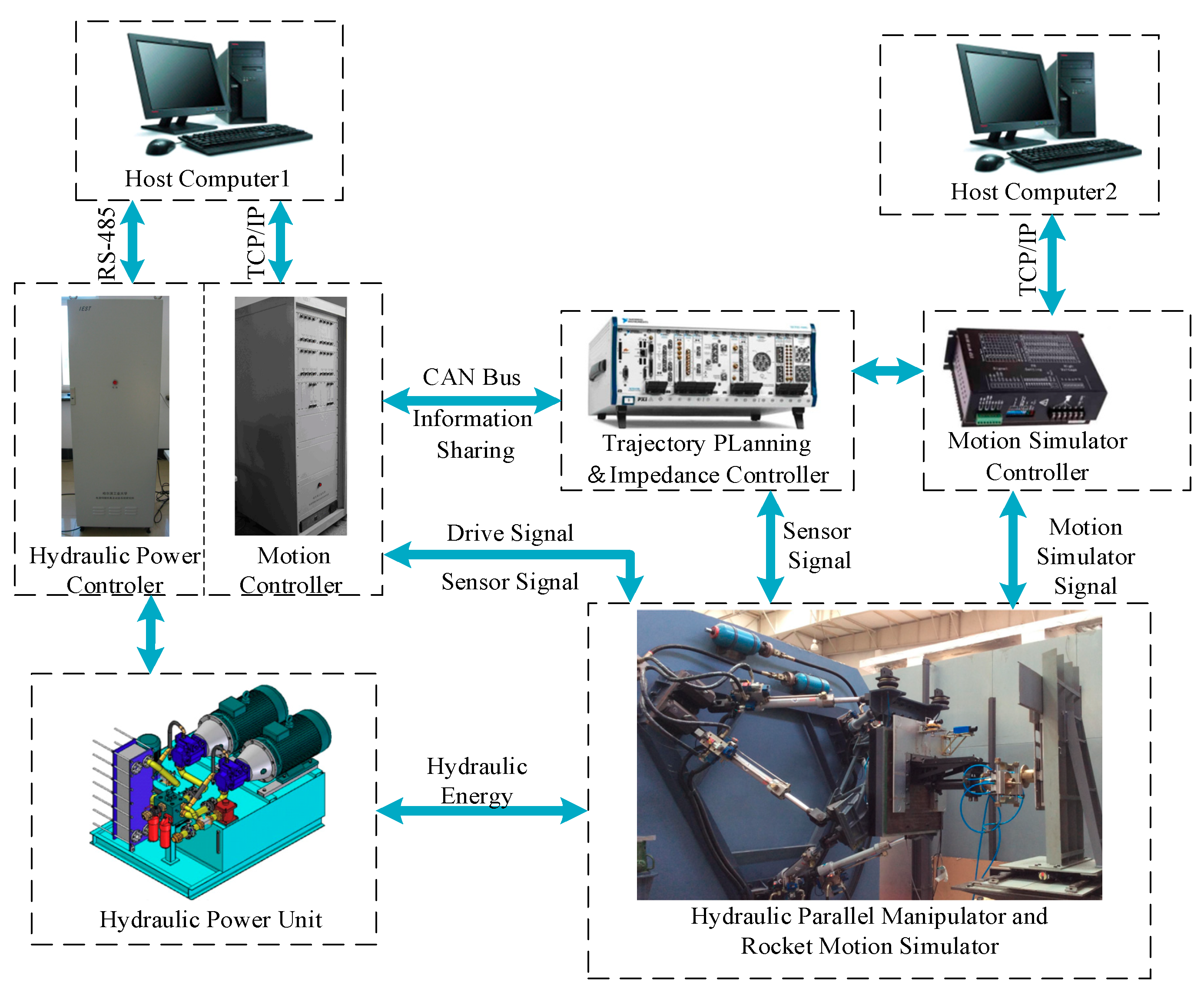
The overall experiment system includes two subsystems as shown in Figure 18. One part consists of the hydraulic parallel manipulator and the system controller, which includes a hydraulic power manager and motion controller. The other part of the rocket simulation system includes the motion simulator controller and rocket motion simulator. The rocket motion simulator is used to move the target object along xyz, the three orthogonal directions of Cartesian coordinate, in order to simulate the rocket’s realistic motion in the environment, and the simulator manager PC2 is employed to control the docking device to realize tracking, locking, unlocking, and other tasks with the pose information acquired from the vision sensor.
The controllers of the two subsystems are both based on an NI PXI-8196 embedded controller which communicates with the CAN bus. The vision sensor system is composed of a TFN-0130 laser rangefinder with 1 mm measuring accuracy and a SONY Super HAD CCD camera with 658 × 492 image resolution. To measure the interact force during the entire contact process, we employ a 6-dof force plate named BERTEC FP9090, which has a full scale of 2000 N force in the x direction, 10,000 N force in the y and z direction, and 4500 Nm torque around the x direction.
The docking device on the end-effector is equipped with a 97 mm length guide pin while the target object also has two guide holes with special designed chamfers. Each joint of the manipulator is actuated by a hydraulic cylinder with a 450 mm stroke and 66 mm cylinder diameter. The rated pressure of the hydraulic power source is 14 MPa. In consideration of the actuator’s maximum displacement the hydraulic cushioning, the workplace of the parallel manipulator is ±250 mm in the x direction and ±380 mm in the y and z direction. The maximum range of motion and speed of the target movement simulator is ±120 and ±100 mm/s, respectively.
To validate the effectiveness of the proposed algorithm, several dynamic experiments were conducted. First, a dynamic tracking experiment was conducted to evaluate the manipulator’s capability of following a specified trajectory based on hydraulic servo control. Next, an entire dynamic docking experiment was performed to verify the force-tracking control scheme validity.

5.2. Dynamic Tracking Experiment

The main purpose of this experiment was to research the dynamic target tracking performance of the manipulator and validate the inner position control loop (presented in Section 4.1) to prepare for the next state dynamic docking experiment.
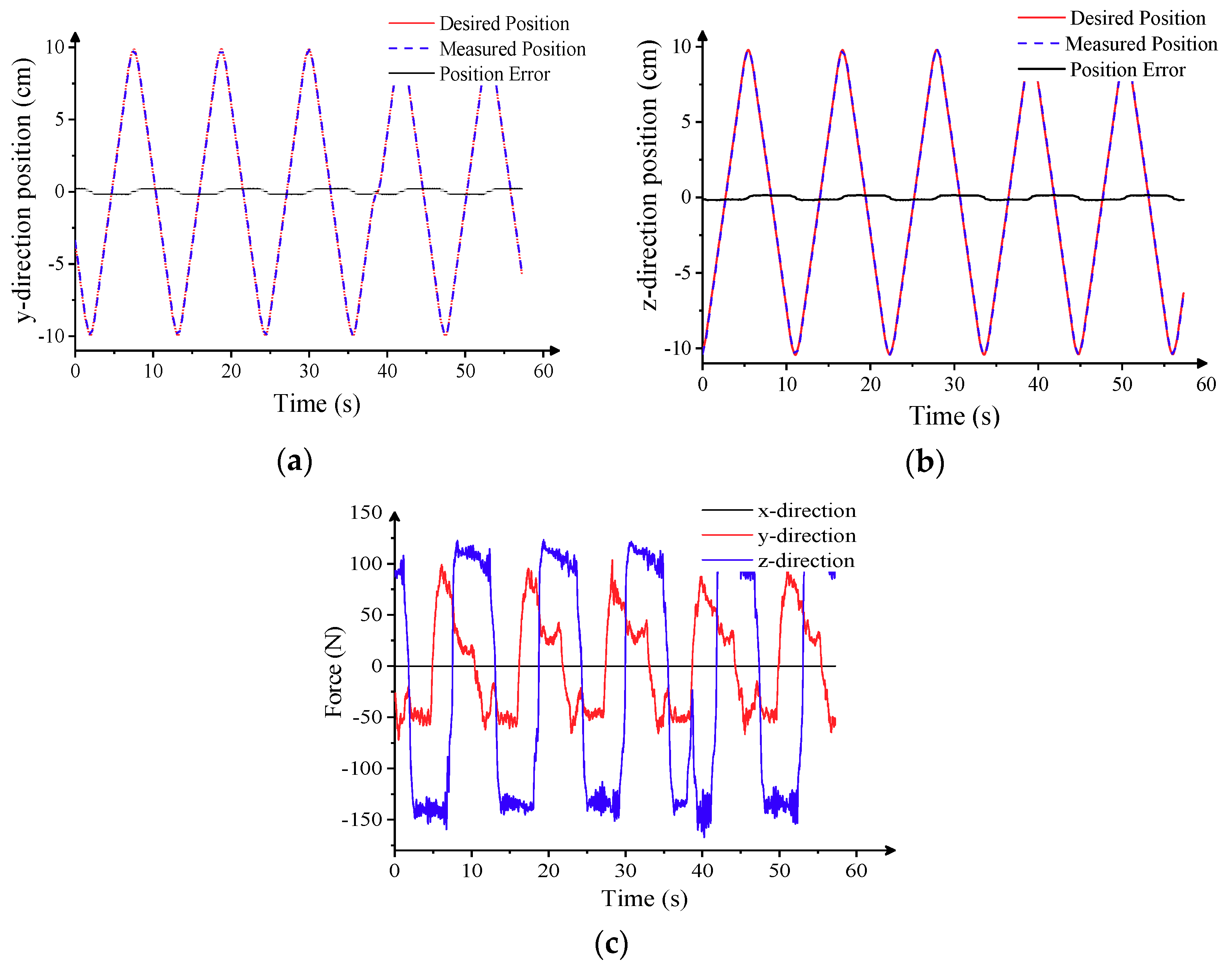
The target’s motion simulator is driven by a stepper motor for triangular wave motion, the amplitude of the triangular wave is ±100 mm, and the moving speed is 100 mm/s in y direction and 80 mm/s in z direction. At the beginning of the experiment, the parallel manipulator was located in its initial position and the midpoint of the triangular wave was x = 0, y = 0, z = 120 mm. The experimental data are shown in Figure 19. Figure 19a,b illustrates the dynamic position tracking data, including the desire and measured position in the x and y direction; Figure 19c illustrates the inertial force caused by the manipulator movement measured by a force sensor plate mounted on the end effector.
In the entire experiment, the relative position error in the y and z directions is comparatively small to ensure successful docking, as shown in Figure 19a,b. Due to the influence of inertial force, force information measured by the force sensor plate presents a triangular wave with relatively small noise. The given positions and the feedback position calculated by the forward kinematics solution are illustrated in Figure 19c. From the position and force information during the tracking process, we can confirm the tracking accuracy of the parallel manipulator and verify the effectiveness of the hydraulic servo control scheme proposed in Section 3.

5.3. Dynamic Inserting Experiment

The purpose of this experiment is to verify the effectiveness of the position/force hybrid control algorithm implemented by the parallel manipulator and the vision system. The entire dynamic docking experiment process is divided into five stages: preparation, approach, docking, following, and returning.
In this experiment, the motion simulator carrying the target object is actuated by stepping motors moving in a triangular wave along the y and z directions. The amplitudes of the triangular wave in two directions are both ±100 mm, while the velocity of the target movement is ±50 mm/s along the y direction and ±40 mm/s along the z direction. In the initial stage of the experiment, the manipulator is located in its initial zero position and the target object is located P 1 = [ 133   ,   26 ,   93 ] in Cartesian coordinates. Then, the experiment enters the next stage and the manipulator begins to track the moving target object in the y and z directions. When the feedback relative position errors in the y and z directions are both less than 10 mm, moving forward command along the x direction generated by the trajectory planning algorithm is given to the manipulator. If the relative distance of the manipulator and the target object is less than 150 mm, the boundary value in which the manipulator is allowed to keep going rises to 7 mm, which will guarantee docking security.
The relative position and force information obtained in the dynamic docking experiment are demonstrated in Figure 20. In the beginning part of the tracking stage, the relative position errors decrease quickly and get into the specific range at 15 s, as shown in Figure 20b. Then, the manipulator approaches the object target smoothly and continuously until the 50 s, when the end effector starts to contact the docking device. From Figure 20c, we can see that the contact force is well controlled under ±150 N in the position/force hybrid control structure, and we can also see that during the tracking stage from 15 to 65 s, the relative position along the x direction controlled by the trajectory generator is comparatively smooth. Experimental results show the relatively favorable efficiency in the design of proposed method.

6. Conclusions

In this paper, a novel automated umbilical mating system based on a hydraulic 6-dof parallel manipulator is proposed to realize the umbilical docking task during the process of rocket propellant loading. A hybrid control strategy of vision, force, and position is proposed, which integrates the three phases of approach, docking, and following in the entire loading process into the same framework, avoiding the impact of switching different control modes on the system stability. The automated docking device adopts a fusion of laser range finder and monocular camera to locate the moving fuel port and guide the automated docking system approaching the rocket fuel port. A hybrid force/position control is applied in the inner loop of the control system to ensure that the contact forces during docking and follow-through remain within a certain range without damaging the rocket. To address the characteristics of the hydraulic parallel mechanism employed in the automated docking device, the nonlinear compensation and gravity compensation are used in the analysis to enhance the dynamic performance of the robot.
A series of experiments were conducted for different working phases of the automated umbilical system. The results show the effectiveness of the proposed algorithm and that the automated docking system has sufficient accuracy and compliance to achieve the working requirements. In the dynamic tracking experiment, the manipulator’s ability to track a high-speed target object is illustrated. When the target object moves at a high speed, up to 50 mm/s, relative position error in the x direction can remain below 10 mm. A dynamic docking experiment is then presented to demonstrate the algorithm’s effectiveness to interact with a high-speed moving target, in which the manipulator is controlled to track and insert into guide holes while the interacting force is well controlled within 300 N.
Some aspects of the control algorithm presented need to be optimized to enhance the experimental performance. The tracking accuracy and contact force control depend on the vision system’s perception precision and resolution. In the next experiment plan, an advanced vision system with higher performance will be employed to measure the target position and orientation. In addition, a novel Kalman filter will be developed to eliminate the signal noise.

Author Contributions

Conceptualization, D.C.; Investigation, H.T.; Methodology, H.T.; Writing—review & editing, H.T. and D.C. Both authors have read and agreed to the published version of the manuscript.

Funding

This research received no external funding.

Institutional Review Board Statement

Not applicable.

Informed Consent Statement

Not applicable.

Data Availability Statement

No publicly archived dataset is used.

Conflicts of Interest

The authors declare no conflict of interest.

References

  1. Gosselin, A.M. Automated ground umbilical systems (AGUS) Project. In Proceedings of the Space Visions Congress, Cocoa Beach, FL, USA, 26–27 April 2007. [Google Scholar]
  2. Li, L.; Chen, J.; Yu, H.; Liu, Q.; Mao, Z. Riseeso control of automatic docking servo system for rocket fuel filling. In Proceedings of the CSAA/IET International Conference on Aircraft Utility Systems (AUS 2020), Online, 18–21 September 2020; pp. 610–615. [Google Scholar]
  3. McLean, C.H. Green propellant infusion mission program overview. In Proceedings of the 49th AIAA/ASME/SAE/ASEE Joint Propulsion Conference, Big Sky, MT, USA, 1–8 March 2014; p. 3847. [Google Scholar]
  4. Walker, M.; Figueroa, F.; Toro-Medina, J. PHM enabled autonomous propellant loading operations. In Proceedings of the 2017 IEEE Aerospace Conference, Big Sky, MT, USA, 4–11 March 2017; pp. 1–11. [Google Scholar]
  5. Dun, X.; Yuan, J.; Chen, L. The auto-docking system design for the fuel loading robot used in hazardous environment. In Proceedings of the 2006 IEEE International Conference on Robotics and Biomimetics, Kunming, China, 17–20 December 2006; pp. 485–490. [Google Scholar]
  6. Ren, H.; Chai, Y.; Qu, J.; Ye, X.; Tang, Q. A novel adaptive fault detection methodology for complex system using deep belief networks and multiple models: A case study on cryogenic propellant loading system. Neurocomputing 2018, 275, 2111–2125. [Google Scholar] [CrossRef]
  7. Song, Z.; Xie, Z.; Qiu, L.; Xiang, D.; LI, J. Prospects of sea launches for Chinese cryogenic liquid-fueled medium-lift launch vehicles. Chin. J. Aeronaut. 2021, 34, 424–437. [Google Scholar] [CrossRef]
  8. Zhou, C.; Yu, C. A Position and Orientation Compensation Mechanism for Automatic Docking Device of Launch Rocket. Trans. Nanjing Univ. Aeronaut. Astronaut. 2018, 35, 1064–1072. [Google Scholar]
  9. You, J.; Huang, Y.; Dun, X. Design and Experimental Study of Automatic Docking and Undocking Robot System for Launch Vehicle Propellant Filling. In Proceedings of the International Conference on Aerospace System Science and Engineering; Springer: Singapore, 2020; pp. 565–578. [Google Scholar]
  10. Han, T.; Dacheng, C. Research on Vision-based Position Measurement System for Rocket Propellant Loading. E3S Web Conf. EDP Sci. 2021, 267, 01046. [Google Scholar] [CrossRef]
  11. Zhong, Y.; Yang, M.; Chen, F. The Response of Vertical Launch Vehicle to Ground Wind. Sci. Technol. Eng. 2010, 24, 6109–6112. [Google Scholar]
  12. Deng, L.; Janabi-Sharifi, F.; Hassanzadeh, I. Comparison of combined vision/force control strategies for robot manipulators. Int. Soc. Opt. Photonics 2005, 6052, 605202. [Google Scholar]
  13. Bellakehal, S.; Andreff, N.; Mezouar, Y.; Tadjine, M. Vision/force control of parallel robots. Mech. Mach. Theory 2011, 46, 1376–1395. [Google Scholar] [CrossRef]
  14. Baeten, J.; Bruyninckx, H.; De Schutter, J. Integrated vision/force robotic servoing in the task frame formalism. Int. J. Robot. Res. 2003, 22, 941–954. [Google Scholar] [CrossRef]
  15. Gao, X.S.; Lei, D.; Liao, Q.; Zhang, G.-F. Generalized Stewart-Gough platforms and their direct kinematics. IEEE Trans. Robot. 2005, 21, 141–151. [Google Scholar]
  16. Ta, T.N.; Tran, C.S.; Hwang, Y.L. The Kinematic and Dynamic Analysis of Hydraulic Control System Based on the Lagrangian Force Method. Int. J. Comput. Methods 2017, 15, 1850041. [Google Scholar] [CrossRef]
  17. Gao, C.; Cong, D.; Liu, X.; Yang, Z.; Tao, H. Hybrid position/force control of 6-dof hydraulic parallel manipulator using force and vision. Ind. Robot Int. J. 2016, 45, 274–283. [Google Scholar] [CrossRef]
  18. Gallardo, J.; Alcaraz, L.A. Kinematics of the Gough-Stewart platform by means of the Newton-homotopy method. IEEE Lat. Am. Trans. 2018, 16, 2850–2856. [Google Scholar] [CrossRef]
  19. Cai, Y.; Zheng, S.; Liu, W.; Qu, Z.; Zhu, J.; Han, J. Sliding-mode control of ship-mounted Stewart platforms for wave compensation using velocity feedforward. Ocean Eng. 2021, 236, 109477. [Google Scholar] [CrossRef]
  20. Lyu, L.; Chen, Z.; Yao, B. Development of pump and valves combined hydraulic system for both high tracking precision and high energy efficiency. IEEE Trans. Ind. Electron. 2018, 66, 7189–7198. [Google Scholar] [CrossRef]
  21. Manring, N.D.; Fales, R.C. Hydraulic Control Systems; John Wiley & Sons: Hoboken, NJ, USA, 2019. [Google Scholar]
  22. Yang, C.; Huang, Q.; Jiang, H.; Ogbobe, P. PD control with gravity compensation for hydraulic 6-DOF parallel manipulator. Mech. Mach. Theory 2010, 45, 666–677. [Google Scholar] [CrossRef]
  23. Zhang, C. PD plus dynamic pressure feedback control for a direct drive stewart manipulator. Energies 2020, 13, 1125. [Google Scholar] [CrossRef] [Green Version]
  24. Yao, J.; Deng, W.; Sun, W. Precision motion control for electro-hydraulic servo systems with noise alleviation: A desired compensation adaptive approach. IEEE ASME Trans. Mechatron. 2017, 22, 1859–1868. [Google Scholar] [CrossRef]
  25. Ba, K.; Ma, G.; Yu, B.; Jin, Z.-G. A nonlinear model-based variable impedance parameters control for position-based impedance control system of hydraulic drive unit. Int. J. Control Autom. Syst. 2020, 18, 1806–1817. [Google Scholar] [CrossRef]
  26. Barmish, B.R.; Tempo, R. The robust root locus. Automatica 1990, 26, 283–292. [Google Scholar] [CrossRef]
  27. Michiels, W.; Engelborghs, K.; Vansevenant, P.; Roose, D. Continuous pole placement for delay equations. Automatica 2002, 38, 747–761. [Google Scholar] [CrossRef] [Green Version]
  28. Zhang, W. Parameter adjustment strategy and experimental development of hydraulic system for wave energy power generation. Symmetry 2020, 12, 711. [Google Scholar] [CrossRef]
  29. Seraji, H.; Colbaugh, R. Force tracking in impedance control. Int. J. Robot. Res. 1997, 16, 97–117. [Google Scholar] [CrossRef]
  30. Jung, S.; Hsia, T.C.; Bonitz, R.G. Force tracking impedance control of robot manipulators under unknown environment. IEEE Trans. Control Syst. Technol. 2004, 12, 474–483. [Google Scholar] [CrossRef]
  31. Surdilovic, D.T. Contact transition stability in the impedance control. In Proceedings of the International Conference on Robotics and Automation, Albuquerque, NM, USA, 25 April 1997; pp. 847–852. [Google Scholar]
  32. Duan, J.; Gan, Y.; Chen, M.; Dai, X. Adaptive variable impedance control for dynamic contact force tracking in uncertain environment. Robot. Auton. Syst. 2018, 102, 54–65. [Google Scholar] [CrossRef]
  33. Maschke, B.; Ortega, R.; Van Der Schaft, A.J. Energy-based Lyapunov functions for forced Hamiltonian systems with dissipation. IEEE Trans. Autom. Control 2000, 45, 1498–1502. [Google Scholar] [CrossRef] [Green Version]
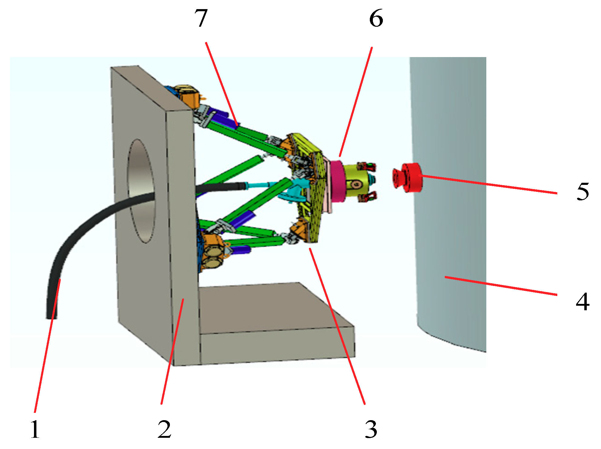
Figure 1. Automated umbilical system: 1, propellant pipeline; 2, launch tower; 3, automated umbilical system; 4, carrier rocket body; 5, propellant filling port; 6, connector and docking device; 7, hydraulic actuators.
Energies 14 04900 g001
Figure 2. Hydraulic manipulator and simulation device: 1, platform basement; 2, HPM; 3, force sensor; 4, end-effector; 5, slideway; 6, target object; 7, planar pattern; 8, laser rangefinder; 9, CCD camera.
Energies 14 04900 g002
Figure 3. Vision system work process.
Energies 14 04900 g003
Figure 4. Image analysis results: (a) original image, (b) binary image, (c) target recognition, (d) target center detection, (e) target center estimation, (f) target orientation estimation.
Energies 14 04900 g004aEnergies 14 04900 g004b
Figure 5. Schematic diagram of cylinder system.
Energies 14 04900 g005
Figure 6. Nonlinear model of the electrohydraulic servo system.
Energies 14 04900 g006
Figure 7. Flow nonlinear compensation control.
Energies 14 04900 g007
Figure 8. Effect of nonlinear compensation control: (a) 5 Hz, (b) 10 Hz, (c) 20 Hz, (d) 30 Hz.
Energies 14 04900 g008
Figure 9. Flow nonlinear compensation control.
Energies 14 04900 g009
Figure 10. Three-state feedback control block diagram.
Energies 14 04900 g010
Figure 11. Three-state feedback effect diagram: (a) frequency characteristics and (b) step response.
Energies 14 04900 g011
Figure 12. Position-based impedance control strategy.
Energies 14 04900 g012
Figure 13. Simplified model of robot–environment contact.
Energies 14 04900 g013
Figure 14. Force control based on online environmental parameter estimation.
Energies 14 04900 g014
Figure 15. Simulation diagram of environmental stiffness estimation.
Energies 14 04900 g015
Figure 16. Simulation diagram of environmental location estimation.
Energies 14 04900 g016
Figure 17. Overall control scheme.
Energies 14 04900 g017
Figure 18. Experimental system structure.
Energies 14 04900 g018
Figure 19. Dynamic tracking experiment: (a) y-direction position tracking, (b) z-direction position tracking, and (c) inertial force.
Energies 14 04900 g019
Figure 20. Dynamic inserting experiment: (a) position tracking, (b) motion error, and (c) interaction force.
Energies 14 04900 g020
Table 1. Hydraulic cylinder parameters.
SymbolNameValue
D1Piston diameter40 mm
D2Piston rod diameter28 mm
LwHydraulic cylinder stroke±196 mm
εCylinder buffer length25 mm
l0Cylinder initial length1200 mm
lmaxCylinder initial length1617 mm
vmaPiston rod maximum speed0.25 m/s
Publisher’s Note: MDPI stays neutral with regard to jurisdictional claims in published maps and institutional affiliations.