Article

Induction Motor PI Observer with Reduced-Order Integrating Unit

Faculty of Electrical Engineering, Silesian University of Technology, 2a Akademicka St., 44-100 Gliwice, Poland
*
Author to whom correspondence should be addressed.
Energies 2021, 14(16), 4906; https://doi.org/10.3390/en14164906
Submission received: 27 July 2021 / Revised: 9 August 2021 / Accepted: 9 August 2021 / Published: 11 August 2021
(This article belongs to the Special Issue Failure Diagnosis and Prognosis of Induction Machines)

Abstract

:
This article presents an innovative induction motor state observer designed to reconstruct magnetic fluxes and the angular speed of an induction motor for speed sensorless control system applications such as field-oriented control (FOC). This observer is an intermediate solution between the proportional observer and the classical proportional-integral (PI) observer with respect to which the order of the integrating unit is reduced. Additional modifications of the observer’s structure have been implemented to ensure stability and to improve its functional properties. As a result, two versions of the observer structure were produced and experimentally tested using a sensorless FOC control system. Both structures resulted in correct control system operation for a wide range of angular speeds, including low speed ranges.

1. Introduction

In electric drives with induction motors based on dynamic control methods such as field-oriented control (FOC) [1,2,3,4,5], it is necessary to reconstruct motor state variables such as components of magnetic fluxes coupled with the stator and rotor windings. The Luenberger observer can be used for this task [1,6,7,8]. Additionally, the angular speed of the motor rotor can be estimated from the state variables reconstructed in the observer [6,8,9]. This makes it possible to obtain a speed-sensorless control system where the angular speed measurement is not required [1,10,11]. Removal of the mechanical angular speed sensor, located on the motor shaft, simplifies the drive system and increases its reliability [12]. Another possibility is to use the angular speed reconstruction along with its measured value. Combining these measurements can be used to develop fail-safe (fault-tolerant) drives that switch to a sensorless mode in the event of an angular speed sensor failure [5,13]. There are also online diagnostic strategies for failure detection based on comparisons of the measured angular speed measured with reconstructed values using an observer [3,8]. When a fault is detected, the drive may switch from the closed-loop mode (e.g., FOC) to the open-loop control (e.g., scalar volts per hertz V/f) [14].
In all previously mentioned cases, the state variable reconstruction quality in the observer had a crucial impact on the control system performance. Therefore, the search for new and better observer structures remains ongoing. The most commonly used Luenberger observer of induction motor state variable reconstruction is the proportional observer [6,15]. Due to the stronger feedback, the proportional-integral (PI) observer provides better reconstruction quality [16,17]. However, this observer has a more complicated structure, and the gain selection is much more difficult [18]. As such, PI observers are rarely used to reconstruct the magnetic flux components for control and speed estimation purposes. Instead, PI observers are typically used for rotor temperature estimation [19] or as a part of a fault detection strategy [20]. Therefore, we propose the use of a PI observer with a reduced integrating unit order (PIr) [21], which can be implemented more easily while offering better reconstruction quality over the proportional observer. Until now, this observer has not been used in induction motor control systems for the reconstruction of magnetic flux components. We report the first successful application of a PIr observer for magnetic flux reconstruction in induction motor control systems along with the experimental results.

2. Methods

The induction motor state observer design process consists of several stages, which are outlined in Figure 1. The starting point is the classical PI observer established by systems and control theory [17]. To create a PIr observer, the feedback integrating unit structure should be modified to limit the number of signals. At the same time, steps should be taken to protect the observer from structural instability. The PI observer, along with other types of non-proportional observers [7,22], can always be unstable for a certain class of dynamic systems, regardless of the gain selection. Induction motors belong to this system class. We proposed a solution to this problem [7,22] through replacement of the integrator with a first-order inertia. A reduction in the integrating unit order should also be performed in such a way to provide the observer with practical properties, resulting directly from the mathematical model structure of the motor [7]. For this purpose, we proposed the idea of combining component values in pairs to modify the observer gain matrices. The introduction of this limitation leads to two possible integrating unit order reduction methods and, finally, to two possible induction motor PIr observer forms.

2.1. Mathematical Model of an Induction Motor

The basis for the observer design is the mathematical model of the induction motor in the form of a linear dynamic system [6,23,24] described by the matrix differential state equation and the matrix algebraic output equation:
{ x ˙ = A x + B u y = C x .
The state vector x n , input vector u p , and output vector y q are defined as follows:
x = [ ψ s α ψ s β ψ r α ψ r β ] ,   u = [ u s α u s β ] ,   y = [ i r α i r β ] .
From Equation (2), it follows that, for an induction motor, the dimensions of consecutive vectors of the system in Equation (1) are as follows: n = 4 , p = 2 , and q = 2 . The vectors x , y , and u contain the variables describing the electromagnetic properties of the induction motor, expressed in relative quantities p.u. (per-unit system). The per-unit system is one of relative units widely used in electric drives theory [25,26]. Furthermore, the quantities contained by the vectors x , y , and u are defined by the Cartesian stationary coordinate system α - β . In Equation (2), ψ is the magnetic flux coupled with the winding, u is the supply voltage of the winding, and i is the winding current. The subscripts s and r denote the quantities related to the stator and rotor windings, respectively. The subscripts α and β denote phasor components corresponding to the axes of the Cartesian coordinate system.
The matrices in Equation (1) have a block structure displaying a particular type of symmetry closely related to the motor properties. Namely, they are block matrices composed of elementary 2 × 2 square matrices, the elements of which are related as follows [15]:
J ( u , v ) = [ u ω v ω v u ] ,
where u and v are real constants and ω is the electrical angular speed of the motor.
The presence of angular speed in the matrices of the state in Equation (1) causes the values of these matrices to vary over time. However, it follows from the motor properties that the angular speed changes much more slowly than the electromagnetic quantities contained in the x , y , and u vectors, so it can be considered constant (parameter) [27]. Thus, the system in Equation (1) can still be treated as a linear system. The matrices have the following forms:
A = [ J ( γ R s L r , 0 ) J ( γ R s L m , 0 ) J ( γ R r L m , 0 ) J ( γ R r L s , 1 ) ] ,   B = [ 1 2 0 2 × 2 ] ,   C = [ γ L r 1 2 γ L m 1 2 ] .
Matrices A , B , and C contain the parameters of the equivalent circuit describing the motor [24]; R s and R r are the resistances of the stator and rotor windings; and L s , L r , and L m are the inductances of the stator winding, rotor winding, and magnetizing one, respectively. Furthermore, 1 2 is a 2nd-order identity matrix, 0 2 × 2 is a 2 × 2 zero matrix, and γ = ( L m 2 L s L r ) 1 .

2.2. PI Observer and Integrating Unit Order Reduction Idea

In general, the Luenberger observer consists of a copy of the mathematical model of the observed system and a corrective feedback loop. A copy of an observed system is driven using the same input as the observed system. The difference between the outputs of the system and its copy is a measure of state variable reconstruction errors and is used to generate the correction signal. Corrective feedback can have a different structure [7]. The most common is the simplest—proportional. However, proportional-integral (PI) feedback is also popular. The classical PI [16,17] observer of the system Equation (1) is described by the state equation:
x ^ ˙ = A x ^ + B u + K P ( y ^ y ) + 0 t K I ( y ^ y ) d t
where y ^ = C x ^ .
In Equation (5), K P and K I are the gain matrices of proportional and integral units, respectively. The state vector of the observed system, reconstructed by the observer, is denoted by x ^ . From this point on, all quantities reconstructed in the observer are distinguished with the circumflex (   ^ ). In Equation (5), both the K P and K I matrices have the same dimensions, so both units use all signals included in the difference y ^ y , and their output signals affect all signals included in the vector x ^ .
Due to the correction signal generated by the integrating unit, the value of which increases with time so long as y ^ y   0 , the PI observer attenuates the reconstruction errors much more strongly than the proportional observer. However, in the case, for example, when the y signal contains a significant amount of measurement noise, the strong PI feedback may degrade the reconstruction quality of the state variables. In this case, a PI observer with a reduced order of the integrating unit (PIr) may be used.
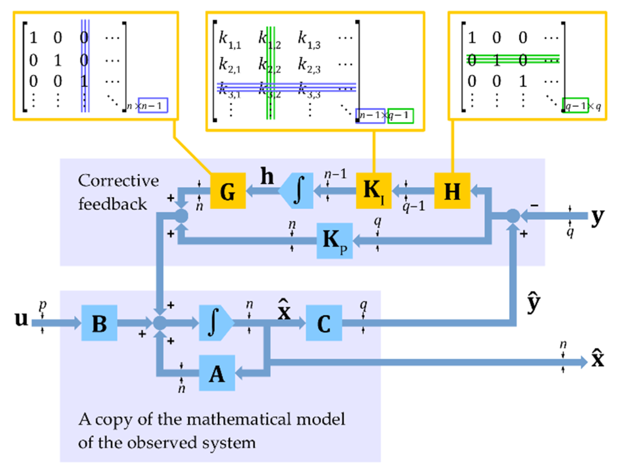
A general schematic describing the order reduction in the integrating unit [21] is presented in Figure 2. Two additional matrices, G and H , were introduced into the mathematical model of the PI observer:
x ^ ˙ = A x ^ + B u + K P ( y ^ y ) + G 0 t K I H ( y ^ y ) d t .
Assuming that G and H are initialized as identity matrices with appropriate orders, the obtained model of the observer in Equation (6) is identical to Equation (5). The G and H matrices are located at the input and output of the integrating unit. At this point, one of the G matrix columns (Figure 2) can be removed. To reconcile the dimensions of the matrices, the row of the gain matrix K I corresponding to this column can also be removed. In this way, the integrating unit no longer has to correct the value of one of the signals contained in the vector x ^ . Similarly, we can remove one row of the matrix H and the corresponding column of the K I gain matrix. Thus, one of the signals used by the integrating unit from the difference y ^ y to generate the correction signal is eliminated. By continuing this course of action, any degree of reduction in the integrating unit order can be obtained.
PI and PIr observers and other observers with non-proportional feedbacks are prone to constant component accumulation, leading to numeric errors [22]. This problem concerns various estimation techniques applied for an induction motor [28]. Non-proportional observers may also experience structural instability that cannot be corrected by selecting the gains [22]. Both problems can be solved by replacing the integrator in the observer feedback with a first-order inertia. After transforming the integral differential Equation (6) into a system of ordinary differential equations,
{ x ^ ˙ = A x ^ + B u + K P ( C x ^ y ) + G h h ˙ = Ω h + K I H ( C x ^ y ) ,
the correction consists of introducing an additional term containing the matrix Ω where Ω is a diagonal matrix containing the reciprocals of the inertia time constants τ greater than zero.
The observer equation forms, Equations (6) and (7), contain two separate gain matrices for K P and K I . To select the included gains in these matrices, these equations should be transformed into a normal form single differential equation. To do this, a new vector of observer state variables and gain matrix can be introduced:
x o = [ x ^ h ] ,   K = [ K P K I H ] .
After performing the appropriate transformations, Equation (7) takes the same form as the proportional observer’s state equation [7]:
x ˙ o = A o x o + B o u + K ( C o x o y ) .
Based on Equation (9), the PIr observer gains in the K matrix can be selected using the same methods used for the proportional observer’s gains. The forms of the matrices A o , B o , and C o depend on the order reduction of the integrating unit. Therefore, it is difficult to provide general forms that take all possible cases into account. Matrix forms limited to the case of the induction motor state variable observer are provided in Section 2.3.

2.3. PIr Observer of an Induction Motor

The mathematical model of the induction motor described by Equations (1)–(2) is characterized by the symmetry outlined by the general rule in Equation (3). From a practical point of view, it is advantageous for the mathematical model of the observer to fulfill this condition since the dynamic properties of the observer become independent of the direction of the motor’s rotor rotation. To fulfill this condition, an appropriate reduction in the observer’s integrating unit order is required. An analysis of Equations (1)–(3) shows that the motor state variables, inputs, and outputs occur in pairs. Each pair contains two phasor components for the α and β axes of the Cartesian coordinate system. Therefore, when reducing the integrating unit order, the rows and columns of the G , H , and K I matrices should also be removed in pairs to follow the rule in Equation (3).
In the case of an induction motor, n = 4 and q = 2 . This means that G is a 4th-order identity matrix and that H is a 2nd-order identity matrix before undergoing any order reduction. In the case of the matrix H , no reduction is possible since even a single order reduction would remove the integral unit completely. In the case of the G matrix, two columns can be removed. Referring back to the rule in Equation (3), these can be the first two or last two columns. Therefore, two forms of matrix G and one form of matrix H are possible:
G s = [ 1 2 0 2 × 2 ] ,   G r = [ 0 2 × 2 1 2 ] ,   H = 1 2 .
Due to the fact that the matrix H is an identity matrix, it was omitted. Taking into account Equations (1)–(3) and (9)–(10), the PIr observer matrices in the proportional observer form are as follows:
A o = [ A G 0 2 × 4 Ω ] ,   B o = [ B 0 2 × 2 ] ,   C o = [ C 0 2 × 2 ] ,   K = [ J ( a , b ) J ( c , d ) J ( e , f ) ] ,
where Ω = τ 1 1 2 and a , b , c , d , e , and f are the observer gains satisfying the symmetry condition in Equation (3). The block diagram of the obtained observer is shown in Figure 3.
Two versions of the induction motor PIr observer corresponding to the matrices G s and G r were obtained by this process. An analysis of the observer’s structure shows that, in the observer based on the G s matrix, the correction signal generated by the integrating unit directly affects the state variables related to the stator winding of the motor. When the G r matrix is applied, this signal directly affects the state variables related to the rotor winding. The first of these observers is hereinafter referred to as PIrS and the second as PIrR.
Now, the obtained mathematical model of the PIr observer is compared with the classical PI observer model. The matrices of the PI observer described by Equation (9) have the following forms:
A o = [ A 1 4 0 4 × 4 Ω ] ,   B o = [ B 0 4 × 2 ] ,   C o = [ C 0 4 × 2 ] ,   K = [ J ( a , b ) J ( c , d ) J ( e , f ) J ( g , h ) ] ,
where Ω = τ 1 1 4 .
The PIr observer has a simpler structure and fewer gains to be calculated, making it easier to apply.

3. Results

For experimental purposes, an induction motor rated at 7.5 kW was used. The observer’s mathematical model was based on relative p.u. values [25,26], using the following base quantities:
U b = U n ,   I b = 3 I n ,   ω b = 2 π f n ,   t b = ω b 1 , Z b = U b I b 1 ,   L b = U b I b 1 ω b 1 ,   ψ b = U b ω b 1 ,   T b = p p U b I b ω b 1 ,
where subscript b denotes a base quantity. Specifically, Z b and L b are the base impedance and base inductance, respectively; T b is the base torque; t b is the base time; and p p is the number of motor pole pairs.
The motor parameters are listed in Table 1. All values in Table 1 are the same as those in the simulation model attached to the article [7]. Therefore, the gain values of the examined observers provided below can be used in the mentioned simulation model. During the experimental tests, the motor operated in the sensorless field-oriented vector control system (FOC). To provide sensorless control, the studied observers were equipped with an angular speed reconstruction mechanism (Figure 4), the same as that described by Kubota at al. [6]. Additionally, the experimental setup used an optical encoder to measure the speed, but this signal was not used by the FOC control system (Figure 4).
In the described experimental system, two observers were tested where the gains were selected using an optimization method based on the genetic algorithm described in [7]. The resultant observer gains obtained as a result of the selection process are listed in Table 2.
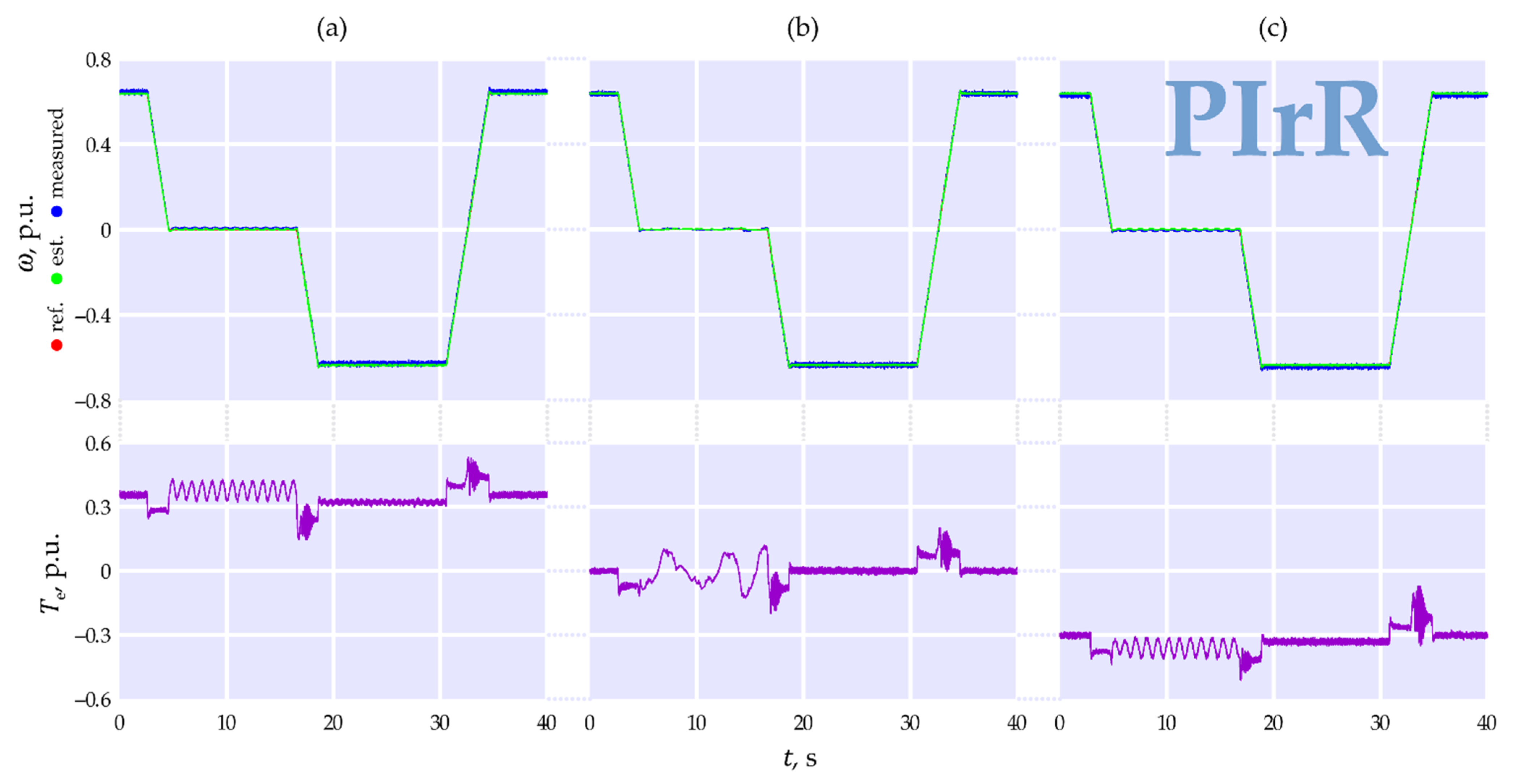
Two sets of tests were performed for each observer, each consisting of several consecutive transients. The first set of tests was performed for relatively high angular speeds, with an initial reference angular speed ω ref of 0.64 p.u. (1 p.u. corresponds to the rated synchronous speed of the motor). During the transients, the reference angular speed changed at a rate of 0.32 p.u. per second, decreasing to 0 followed by −0.64 and then returning to the initial value. This test was repeated three times, once for each of the following conditions: the motor loaded with a constantly positive load torque (Figure 5a, Figure 6a, Figure 7a and Figure 8a), zero load torque (idle-run, Figure 5b, Figure 6b, Figure 7b and Figure 8b), and constantly negative load torque (Figure 5c, Figure 6c, Figure 7c and Figure 8c). Constant positive torque means that the torque direction is the same as for the nominal torque of the motor, independent of the direction of the angular speed. This was achieved through the use of an active load realized by a properly controlled DC machine (Figure 4a). It should be noted that, when the speed has the same sign as the torque, motor operation occurs.
When speed and torque have opposite signs, the motor operates in a regenerative mode (generator operation) and returns energy to the supply network. The results for the PIrS and PIrR observers are shown in Figure 5 and Figure 6, respectively. The graphs show the courses of the reference angular speed of the FOC control system ω ref , the speed estimated in the observer, and the measured speed. The course of the calculated electromagnetic torque of the motor T e is also presented based on the magnetic fluxes reconstructed in the observer and the measured currents of the stator winding.
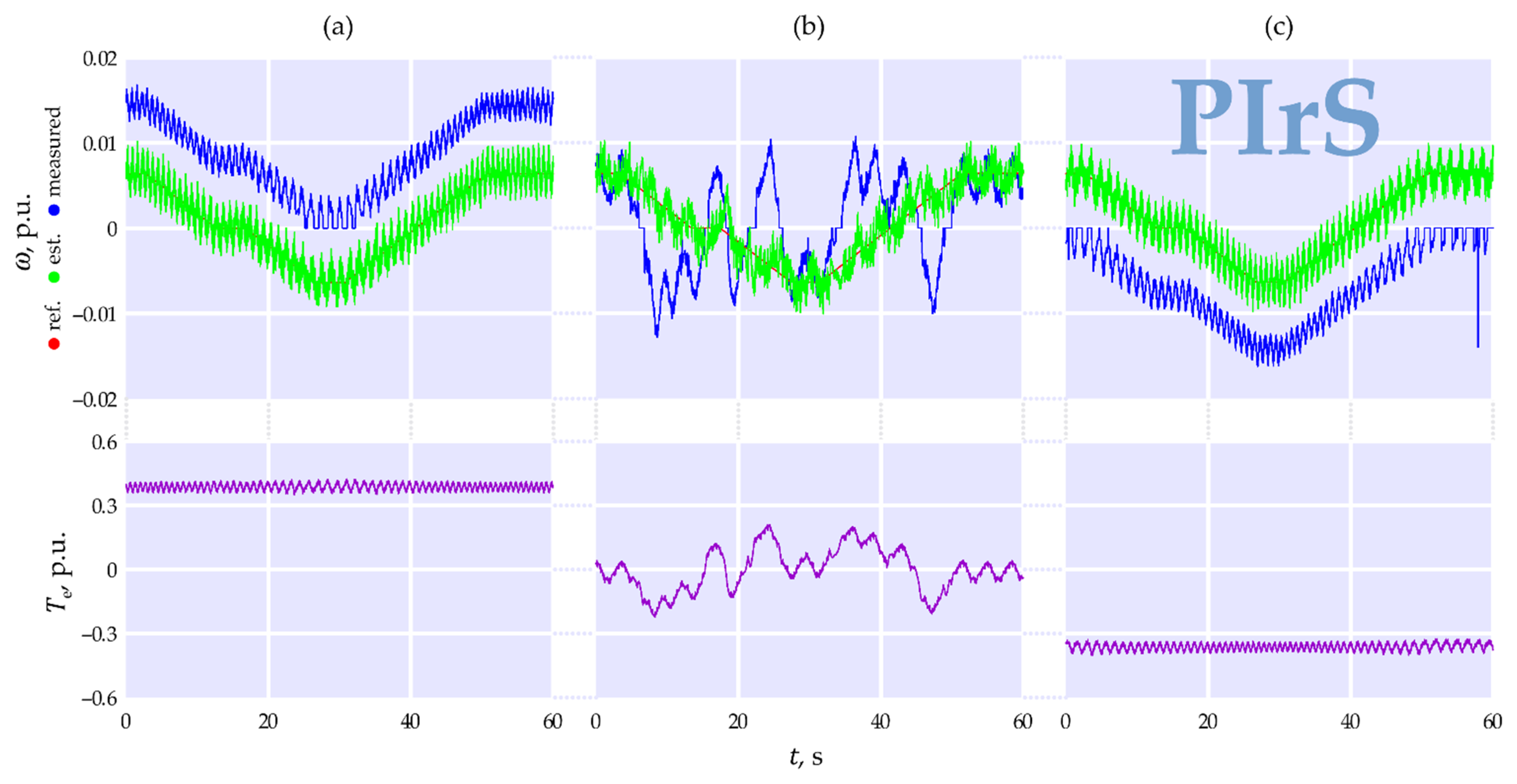
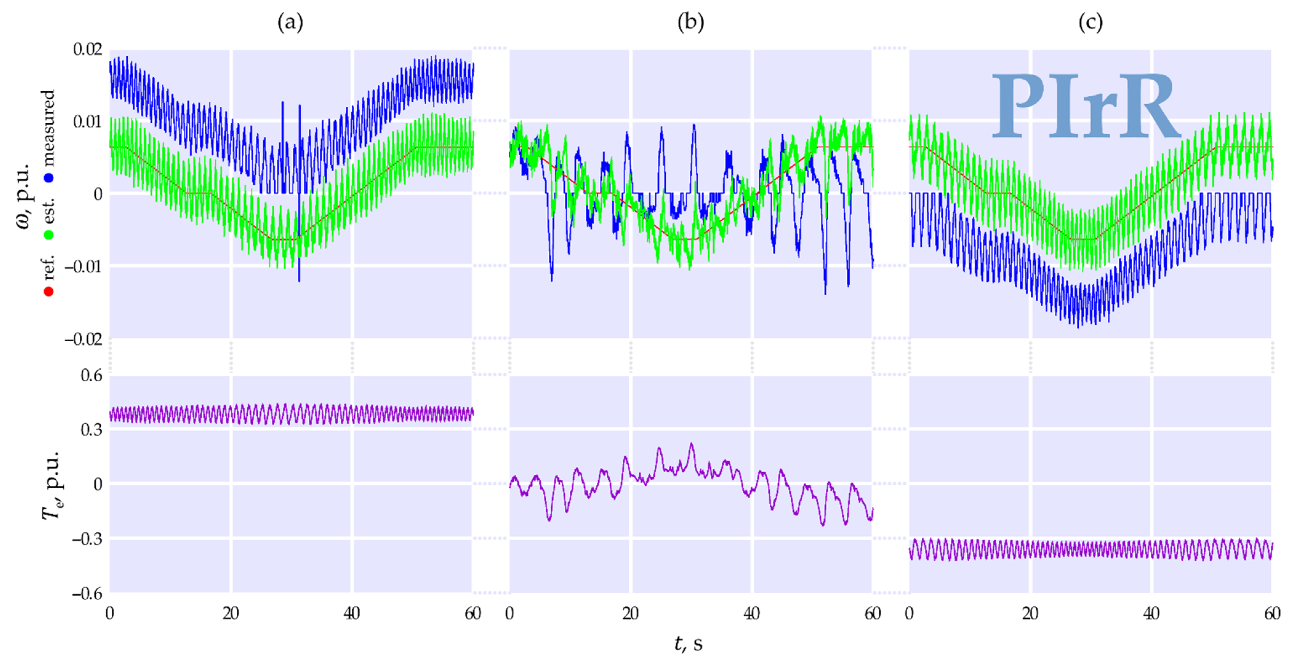
The second set of tests was carried out for very low angular speeds with an initial reference speed ω ref of 0.0064 p.u. In transient states, the reference speed changed by 0.00064 p.u. per second. The test was also carried out three times for three different load torques. The measurement results for the PIrS and PIrR observers are shown in Figure 7 and Figure 8, respectively.

4. Discussion

The graphs presented in Figure 5 and Figure 6 show that both observers ensured correct operation of the control system for a wide range of angular speeds. The PIrR observer fared better in these tests than the PIrS observer, where strong oscillations in the reconstructed angular speed, marked with arrows in Figure 5a–c, are visible. These oscillations, through feedback from the control system, are reflected in the waveform of the electromagnetic torque of the motor T e . Both observers show a visible offset in the measured speed (blue) in relation to the reference and reconstructed speed (red and green, respectively). This offset is due to the voltage drop at the inverter transistors and the PWM dead time. This is evidenced by the constant value of this shift, regardless of the angular speed, and its direction (up or down) depending on the direction of the electromagnetic torque T e . Due to the constant value of this shift, it is most noticeable for very low rotational speeds (Figure 7 and Figure 8).
At very low speeds, significant oscillations in the reconstructed angular speed are visible, the period of which decreases with increasing speed. This proves that they are the result of deformation in the magnetic field distribution in the air gap of the motor. The mathematical model of the motor (Equation (1)) is based on the assumption that this distribution is sinusoidal, while in real-world conditions, the distribution is actually more trapezoidal. These oscillations may also result from parameter shifts in the equivalent circuit for the winding’s phases resulting from manufacturing tolerances. It should be noted that, in Figure 7 and Figure 8, the maximum measured (averaged) angular speed is about 0.015 p.u. This corresponds to the time of one full revolution of the rotor t rev = 2 π p p ω 1 = 838   p . u . (2.67 s). At such low angular speeds, the position of the magnetic field in relation to the windings of respective motor phases has a significant impact on the results obtained for parameter shifts in these phases. Therefore, ensuring the correct operation of the control system is difficult under such conditions, and both observers succeeded in this task. The PIrS observer performs better under load (Figure 7 and Figure 8a,c), as evidenced by the lower oscillation values of the reconstructed speed. In the case of idle-run (Figure 7b and Figure 8b), the transients of both observers are very irregular with a slight advantage in favor of the PIrR observer. It should be noted that, during the idle-run, the stator winding currents are small, meaning that the measurement noise in their waveforms is relatively high. This noise hinders operation of the observer’s corrective feedback, which uses the current information contained in the y vector. Therefore, from the observer’s point of view, idle-run of the motor is a difficult operating condition that results in a lower quality of the reconstructed speed waveforms.

5. Conclusions

Both proposed observer structures, PIrS and PIrR, guarantee correct operation of the induction motor control system for a wide range of angular speeds. In terms of the quality of the angular speed reconstruction, a slight advantage of the PIrR observer is visible.
The proposed observers have been tested in the FOC control system, but they can also be used in other types of induction motor control systems, such as direct torque control (DTC) or multiscalar control [18,22,24].

Author Contributions

Conceptualization, T.B.; methodology, T.B., R.N., J.M. and M.P.; software, T.B. and R.N.; validation, M.P.; formal analysis, T.B.; investigation, T.B., R.N. and J.M.; data curation, R.N. and J.M.; writing—original draft preparation, T.B.; writing—review and editing, T.B., R.N., J.M. and M.P.; visualization, T.B. and R.N.; supervision, M.P. All authors have read and agreed to the published version of the manuscript.

Funding

This research received no external funding

Institutional Review Board Statement

Not applicable.

Informed Consent Statement

Not applicable.

Conflicts of Interest

The authors declare no conflict of interest.

References

  1. Laatra, Y.; Lotfi, H.; Abdelhani, B. Speed Sensorless Vector Control of Induction Machine with Luenberger observer and Kalman Filter. In Proceedings of the 2017 4th International Conference on Control, Decision and Information Technologies (CoDIT’17), Barcelona, Spain, 5–7 April 2017; pp. 5–7. [Google Scholar] [CrossRef]
  2. Wang, F.; Zhang, Z.; Mei, X.; Rodríguez, J.; Kennel, R. Advanced Control Strategies of Induction Machine: Field Oriented Control, Direct Torque Control and Model Predictive Control. Energies 2018, 11, 120. [Google Scholar] [CrossRef] [Green Version]
  3. Kuchar, M.; Palacky, P.; Simonik, P.; Strossa, J. Self-Tuning Observer for Sensor Fault-Tolerant Control of Induction Motor Drive. Energies 2021, 14, 2564. [Google Scholar] [CrossRef]
  4. Toumi, D.; Segueir Boucherit, M.; Tadjine, M. Observer-based fault diagnosis and field oriented fault tolerant control of induction motor with stator inter-turn fault. Arch. Electrical Eng. 2012, 61, 165–188. [Google Scholar] [CrossRef]
  5. Tran, C.D.; Palacky, P.; Kuchar, M.; Brandstetter, P.; Dinh, B.H. Current and Speed Sensor Fault Diagnosis Method Applied to Induction Motor Drive. IEEE Access 2021, 9, 38660–38672. [Google Scholar] [CrossRef]
  6. Kubota, H.; Matsuse, K.; Nakano, T. DSP-based speed adaptive flux observer of induction motor. IEEE Trans. Ind. Appl. 1993, 27, 344–348. [Google Scholar] [CrossRef]
  7. Białoń, T.; Pasko, M.; Niestrój, R. Developing Induction Motor State Observers with Increased Robustness. Energies 2020, 13, 5487. [Google Scholar] [CrossRef]
  8. Azzoug, V.; Menacer, A.; Pusca, R.; Romary, R.; Ameid, T.; Ammar, A. Fault Tolerant Control for Speed Sensor Failure in Induction Motor Drive based on Direct Torque Control and Adaptive Stator Flux Observer. In Proceedings of the International Conference on Applied and Theoretical Electricity (ICATE), Craiova, Romania, 4–6 October 2018; pp. 1–6. [Google Scholar] [CrossRef]
  9. Aziz, A.G.M.A.; Rez, H.; Diab, A.A.Z. Robust Sensorless Model-Predictive Torque Flux Control for High-Performance Induction Motor Drives. Mathematics 2021, 9, 403. [Google Scholar] [CrossRef]
  10. Zaky, M.S.; Khater, M.; Yasin, H.; Shokralla, S.S. Review of different speed estimation schemes for sensorless induction motor drives. J. Electr. Eng. 2008, 8, 102–140. [Google Scholar]
  11. Kadrine, A.; Tir, Z.; Malik, O.P.; Hamida, M.A.; Reatti, A.; Houari, A. Adaptive non-linear high gain observer based sensorless speed estimation of an induction motor. J. Franklin Inst. 2020, 357, 8995–9024. [Google Scholar] [CrossRef]
  12. Fnaiech, M.A.; Guzinski, J.; Trabelsi, M.; Kouzou, A.; Benbouzid, M.; Luksza, K. MRAS-Based Switching Linear Feedback Strategy for Sensorless Speed Control of Induction Motor Drives. Energies 2021, 14, 3083. [Google Scholar] [CrossRef]
  13. Najafabadi, T.A.; Salmasi, F.R.; Jabehdar-Maralani, P. Detection and Isolation of Speed-, DC-Link Voltage-, and Current-Sensor Faults Based on an Adaptive Observer in Induction-Motor Drives. IEEE Trans. Ind. Electron. 2011, 58, 1662–1672. [Google Scholar] [CrossRef]
  14. Zhang, Z.; Gultekin, M.A.; Bazzi, A.M. State-space Modeling of Multi-mode-controlled Induction Motor Drive. In Proceedings of the IEEE International Electric Machines & Drives Conference (IEMDC), Virtual Conference, Hartford, CT, USA, 17–20 May 2021; pp. 1–5. [Google Scholar] [CrossRef]
  15. Pimkumwong, N.; Wang, M.S. Full-order observer for direct torque control of induction motor based on constant V/F control technique. ISA Trans. 2018, 73, 189–200. [Google Scholar] [CrossRef] [PubMed]
  16. Nazari, S.; Shafai, B. Distributed Proportional-Integral Observers for Fault Detection and Isolation. In Proceedings of the IEEE Conference on Decision and Control (CDC), Miami Beach, FL, USA, 17–19 December 2018; pp. 6328–6333. [Google Scholar]
  17. Wang, X.T.; Yu, H.H. Generalized PI observer design for descriptor linear system. Arch. Cont. Sci. 2019, 29, 585–601. [Google Scholar]
  18. Białoń, T.; Lewicki, A.; Pasko, M.; Niestrój, R. Parameter selection of an adaptive PI state observer for an induction motor. Bull. Pol. Acad. Sci. Tech. Sci. 2013, 61, 599–603. [Google Scholar] [CrossRef] [Green Version]
  19. Gao, Z.; Habetler, T.G.; Harley, R.G.; Colby, R.S. A Sensorless Adaptive Stator Winding Temperature Estimator for Mains-Fed Induction Machines with Continuous-Operation Periodic Duty Cycles. IEEE Trans. Ind. Appl. 2008, 5, 1533–1542. [Google Scholar]
  20. Espinoza-Trejo, D.R.; Campos-Delgado, D.U.; Martinez-Lopez, F.J. Variable Speed Evaluation of a Model-Based Fault Diagnosis Scheme for Induction Motor Drives. In Proceedings of the IEEE International Symposium on Industrial Electronics, Bari, Italy, 4–7 July 2010; pp. 2632–2637. [Google Scholar]
  21. Hussein, A.A.; Salih, S.S.; Ghasm, Y.G. Implementation of Proportional-Integral-Observer Techniques for Load Frequency Control of Power System. In Proceedings of the 8th International Conference on Ambient Systems, Networks and Technologies, ANT-2017 and the 7th International Conference on Sustainable Energy Information Technology, SEIT 2017, Madeira, Portugal, 16–19 May 2017; pp. 754–762. [Google Scholar]
  22. Białoń, T.; Lewicki, A.; Niestrój, R.; Pasko, M. Stability of a proportional observer with additional integrators on the example of the flux observer of induction motor. Electrical Rev. 2011, 87, 142–145. [Google Scholar]
  23. Krzemiński, Z.; Lewicki, A.; Morawiec, M. Speed observer based on extended model of induction machine. In Proceedings of the IEEE International Symposium on Industrial Electronics, Bari, Italy, 4–7 July 2010; pp. 3017–3112. [Google Scholar]
  24. Białoń, T.; Lewicki, A.; Pasko, M.; Niestrój, R. Non-proportional full-order Luenberger observers of induction motors. Arch. Electrical Eng. 2018, 67, 925–937. [Google Scholar]
  25. IEEE. IEEE Standard Definitions of Basic Per Unit Quantities for Alternating-Current Rotating Machines, IEEE Std 86-1975; The Institute of Electrical and Electronics Engineers Inc.: New York, NY, USA, 1975; pp. 1–10. [Google Scholar]
  26. Popescu, M. Induction Motor Modelling for Vector Control Purposes; Helsinki University of Technology: Helsinki, Finland, 2000; 144p, ISBN 951-22-5219-8. [Google Scholar]
  27. Amrane, A.; Larabi, A.; Aitouche, A. Unknown input observer design for fault sensor estimation applied to induction machine. Math. Comput. Simul. 2020, 167, 415–428. [Google Scholar] [CrossRef]
  28. Taherzadeh, M.; Hénao, H.; Capolino, G.A. State of the art of torque observers for condition monitoring of AC drives. In Proceedings of the 2021 IEEE Workshop on Electrical Machines Design, Control and Diagnosis (WEMDCD), Virtual Conference, Modena, Italy, 8–9 April 2021; pp. 289–296. [Google Scholar] [CrossRef]
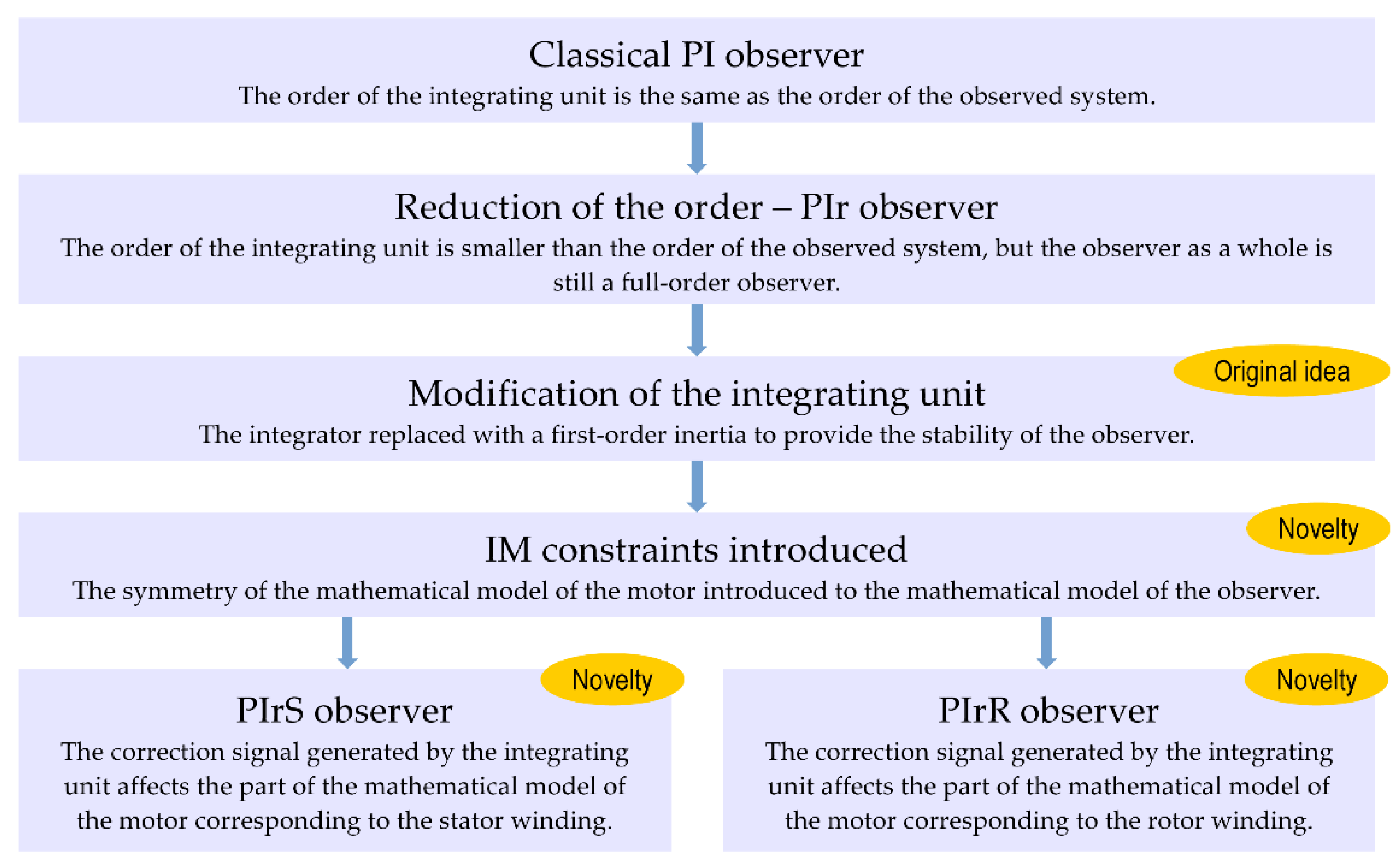
Figure 1. Induction motor PIr observer design methodology.
Energies 14 04906 g001
Figure 2. Cartoon describing the order reduction in the integrating unit of the PI observer.
Energies 14 04906 g002
Figure 3. Schematic of the PIr observer of an induction motor.
Energies 14 04906 g003
Figure 4. Experimental test system (a) and structure of the FOC control system (b).
Energies 14 04906 g004
Figure 5. Measurement results obtained for the PIrS observer at high angular speeds: (a) active positive load torque; (b) idle-run; (c) active negative load torque.
Energies 14 04906 g005
Figure 6. Measurement results obtained for the PIrR observer at high angular speeds: (a) active positive load torque; (b) idle-run; (c) active negative load torque.
Energies 14 04906 g006
Figure 7. Measurement results obtained for the PIrS observer at very low angular speeds: (a) active positive load torque; (b) idle-run; (c) active negative load torque.
Energies 14 04906 g007
Figure 8. Measurement results obtained for the PIrR observer at very low angular speeds: (a) active positive load torque; (b) idle-run; (c) active negative load torque.
Energies 14 04906 g008
Table 1. Rated parameters of the applied induction motor.
DescriptionSymbolAbsolute ValuePer-Unit Value
Rated parameters U n 400 V1 p.u.
I n 14.6 A0.577 p.u.
P n 7.5 kW-
T n 49.4 Nm0.767 p.u.
n n 11450 rpm ( p p = 2 )-
f n 50 Hz-
Base quantities U b 400 V1 p.u.
I b 25.29 A1 p.u.
ω b 314.2 rad/s1 p.u.
t b 3.183 ms1 p.u.
Z b 15.82 Ω1 p.u.
L b 0.05035 H1 p.u.
ψ b 1.273 Wb1 p.u.
T b 64.39 Nm1 p.u.
Equivalent circuit parameters R s 0.56 Ω0.0354 p.u.
R r 0.72 Ω0.04552 p.u.
L s 0.1226 H2.435 p.u.
L r 0.1226 H2.435 p.u.
L m 0.1183 H2.35 p.u.
1 Nominal rotational speed n n   is the mechanical one while angular speed ω is the electrical one.
Table 2. Gains and inertia time constants of the tested observers (p.u.).
Observer a b c d e f τ
PIrS0−0.1406 0.06820−0.02133−0.0317510
PIrR−0.19270.01944−0.106300.0330.113510
Publisher’s Note: MDPI stays neutral with regard to jurisdictional claims in published maps and institutional affiliations.