1. Introduction
Bearingless machines use magnetic forces to support the rotor shaft, reducing losses, and maintenance due to mechanical wear [
1].
Among the topologies of bearingless machines developed in recent years, three-phase bearingless induction machines. In these machines, there are two windings in the stator, a 4-pole winding for torque production and an additional 2-pole winding to promote magnetic bearing of the rotor [
2,
3,
4,
5]. In these works, both windings are three-phase and, therefore, driven by three-phase inverters, one inverter for each winding, this increases the complexity and cost of the drive. An important variant of this machine is the three-phase induction bearingless motor with split winding. In this type of machine, there is only one winding in the stator responsible for simultaneously producing the torque and promoting the magnetic support of the rotor [
6,
7,
8,
9]. These works have the advantage of reducing the space required for the windings, making the machine more compact and, therefore, lighter. However, the coils of each phase are divided into two groups so that the current in each group is individually controlled. This results in the need to separately control six currents leading to a relatively more complex and costly drive structure as a six-legged voltage inverter, six current sensors, two-position sensors, and other auxiliary components as power sources are required. power supply, signal conditioning boards, and digital signal processors.
In order to reduce this drive structure and consequently costs, this work proposes a driving scheme that uses only two-phase currents to control the radial position of the rotor. The current of the third phase necessary for the operation of the machine is obtained by the composition of the two controlled currents. This approach reduces from six to four the number of inverter legs, drivers, and current sensors.
There are other proposals to reduce the costs of starting driving and controlling a bearingless motor without a bearing as in [
10,
11]. However, they are special motors (disk shape) intended for specific applications. Induction motors are robust, low cost, widely used in industry, and extremely reliable [
12,
13].
The driving of three-phase loads using only two phases is nothing new, Refs. [
14,
15] show studies that confirm the possibility of this type of drive, Ref. [
16] presents the two-phase drive of a conventional three-phase motor. Applying the two-phase driving scheme in a three-phase bearingless induction machine with split winding is a new and challenging study once in this system, the control signal for radial position control is superimposed on the current signals produce torque.
This work sought to validate the reduced drive structure as a new way to drive motors without split winding bearings. In this way, the results presented in this text cover the addition of the current control in the machine coils and the radial position control. This is an intermediate step for a more complete analysis of the dynamic performance of the studied motor, which paves the way for the complete dynamics of the system, including the torque and speed control loops, to be studied in future works.
The proposed technique was implemented in a three-phase induction bearingless machine whose radial rotor position is actively controlled with two degrees of freedom. For that, the digital signal processor (DSP) TMS320F28335
from Texas Instruments was used. The experimental results without demonstrated the strategy’s viability loss of performance of the prototype [
17].
2. Radial Forces Generation
Figure 1 shows the process of generating radial position forces on the rotor shaft of a bearingless machine with split windings. For simplicity, only the phase
group of windings are represented.
By feeding coils
and
with the same current
, a magnetic flux
is created as shown by the continuous blue lines in the
Figure 1. When the rotor is centralized on the center of the stator, the magnetic flux densities in both air gaps along the
x-axis are equal and, therefore, there is no net radial force acting on the rotor.
Suppose a value of
is added to the current of coil
and this same value is simultaneously subtracted from the coil
, an additional magnetic flux
, represented by red dashed lines, appears through the magnetic circuit of the
Figure 1. The direction of the incremental magnetic flux generated by
is such that it flows in the same direction of the flux of
and in the opposite direction of the flux of
. This effect makes the total magnetic flux unbalanced and then produces a radial magnetic force in the positive direction of the
x-axis of the rotor. In the vertical direction, the additional flux is canceled and, consequently, there are no resultant forces in this direction.
By means of the differential action on the currents that flow through the two coils, forces can be generated to centralize the position of the rotor in the center. This effect is the same in all pairs of opposing coils, and the force obtained acts along the axis that passes through the center of them. Therefore, in a three-phase machine, positioning forces can be controlled in any direction of the transverse plane, superimposing the effects along the three actuation axes formed by the coil pairs, as shown in
Figure 2.
3. The Drive System
Independent of the control system used (conventional three-phase or two-phase), the bearingless machine with split winding must be fed on its 06 (six) coils to ensure radial positioning and the desired torque. The difference between the systems mentioned is essentially in the number of switches to be controlled. The use of the three-phase drive system requires a drive structure with 12 (twelve) static switches of the IGBT type. Choosing the two-phase system to perform the same task, it will be necessary to control only 08 (eight) keys of the same model, resulting in benefits such as the reduction in costs and dimensions of the power driver, in addition to reducing the computational load on the DSP. In this context, the DSP is the device responsible for all system control steps including: PID type radial position control algorithms and PI type current control algorithms, in addition to generating the pulse width modulation (PWM) signals responsible for the drive static switches (IGBTs). PWM signals are generated by comparing reference currents, with a triangular 10 kHz frequency carrier. After the comparison, the generated PWM signals are made available on the microcontroller’s digital outputs. As the signals supplied by the DSP operate at voltages from 0 to 3.3 Volts, an interface circuit is used to convert them to voltages from −8 to 15 V in order to meet the IGBTs driver specifications. The composition of the PWM signals applied to the static switches allows the flux of currents originating from the DC bus available in the DC–AC converter to the machine’s winding. Thus, the main difference between the three-phase conventional and two-phase drive systems is in the number of controlled coils. In the three-phase system, 06 (six) reference currents are needed to obtain the desired radial position control, as shown in
Figure 3. So that phase A current is a vector composition of the controlled currents of phases B and C, as shown in
Figure 4. Using the proposed two-phase system, one of the phases is put to operate in the configuration shown in
Figure 5.
3.1. Conventional Driving Technique
The stator winding comprises six groups of equal coils, two per phase, as shown in
Figure 2. In order to implement position control, the currents of each group of coils must be controlled separately. For this, a drive circuit is used, composed of six single-phase inverters, as shown in
Figure 3. Each inverter controls the current of a coil group.
In order to guarantee the rotating magnetic field integrity, two coil groups of the same pair (same phase) must be fed by currents of the same phase but 120 out of phase with the other pairs’ currents.
3.2. Winding Currents Composition
Traditionally, the bearingless induction motor with split winding is controlled by six currents generated from the three-phase currents
,
, and
, which are modulated by the radial positioning components,
,
, and
as shown in the set of Equation (
1).
The positioning components
,
, and
are obtained through the vector transformation (
2) of the orthogonal position control signals
and
.
where:
The differential application of the positioning components in (
1) prevents them from interfering with conjugate [
7]. The following analysis can verify this: for example, if the increase in current
in coil
(
Figure 2) causes an increase in torque, subtracting the same value in the current from
will decrease the torque in the same proportion, maintaining the contribution of phase
B conjugate invariant concerning
. The same behavior occurs in the coil pairs of phases
A and
C.
3.3. Proposed Driving Technique
The driving technique proposed in this work makes it possible to control the rotor’s radial position by controlling only two of the machine’s three-phase currents. It can be seen in
Figure 2 that the coils of phases
B and
C are aligned to no-orthogonal axes. These axes, represented in
Figure 4 as
b-axis and
c-axis, form a system of non-orthogonal coordinates capable of composing forces in any direction of the plane. Thus, the radial position’s control can be obtained by adding control actions only in phases
B and
C, leaving the current of phase
A free from control.
In prototype, the position sensors are arranged in orthogonal directions. Therefore, it is necessary to transform the control actions of the
x-axis and
y-axis system (orthogonal) to the
b-axis and
c-axis system. From
Figure 4 it obtain:
In the prototype, the position sensors are arranged in orthogonal directions. Therefore, it is necessary to transform the
x-axis and
y-axis system’s control actions (orthogonal) to the
b-axis and
c-axis system. From
Figure 4, it obtains:
3.4. Obtaining the Winding Currents
Modulating the polarization currents
and
with the respective position control components
and
generate the currents of the
,
,
, and
coils. The following set of equations achieves the modulation:
where
is the amplitude of the currents in Amperes,
is the angular frequency in rad/s, and
t is time in seconds.
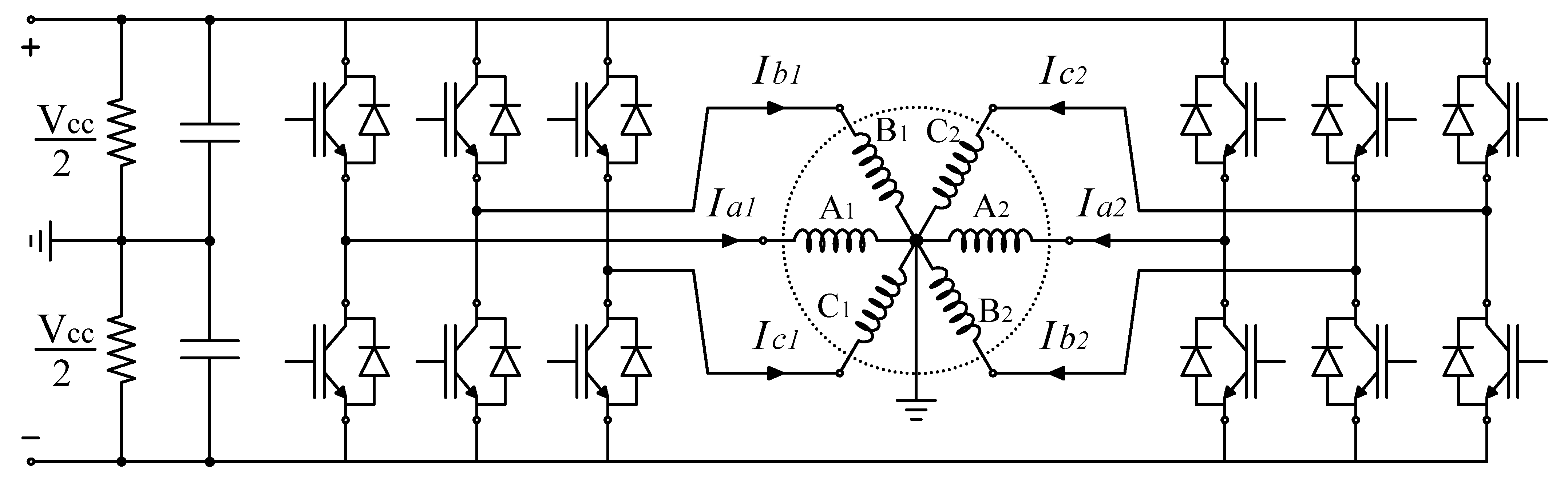
For the drive, the circuit of
Figure 5 obtained by modifying the conventional drive circuit was proposed. Two two-phase inverters were used. Each inverter has 2 IGBT SKM 75GB 176 DN modules. The scalar PWM modulation technique was used, in which the sinusoidal references are generated by the processor. The PWM signals are sent switches through SKHI 23/17 drivers.
The phase
A currents can be determined from the circuit analysis in
Figure 5 as follows:
Replacing the currents
,
,
and
with the values presented in Equation (
5) it is obtained:
It is important to note that current is 120 out of phase with other currents, thus composing a three-phase set of currents. Furthermore, the current is not affected by the modulation components and .
For experimental validation of the drive structure, control of system variables, and collection of results obtained from a DSP from The Texas Instruments model TMS320F28335. This processor is part of the C2000 processor family. It is a 32-bit microcontroller with Havard-modified architecture in which the instruction bus is separate from the data bus. The CPU performs floating point operations and the hardware has a specific AD converter and PWM generation module for driving and controlling machines.
4. Control Diagram
To acquire data from the system, we used a tool embedded on the DSP: an interface that allows loading data and transfer to Matlab in which we fill vectors with data and hold them in the Matlab workspace to display them. Furthermore, the rotor position in mm was determined from the measurement of the air gap length. Then, this value was related to the digital information generated by the DSP AD converter from the response curve of the position sensors.
As it is shown in the
Figure 6 the control scheme is composed of two loops: an external one for radial position control of the rotor on the axes X and Y and an internal one that controls the current on the machine windings. Displacement sensors by eddy currents model PU-05, coupled to an AEC-55 signal converter detect the radial position of the rotor in the
plane. Then these signals are compared with the X
and Y
position references, and the error signals feed PID controllers to calculate the orthogonal control signals
and
. These values are transformed by (
4) to obtain the components
and
. Then, the components are added to the currents
and
to generate the references
,
,
and
to current controllers. The current control is performed by four identical and independent PI controllers. Position control is performed by two identical PID controllers.
Control is performed by a digital signal processor (DSP), the TMS320F28335 from Texas Instruments. It was chosen 10 kHz as inverter’s switching frequency. This same frequency was used to sample the signals.
This first part of the research focused only on the control rotor radial position, so the torque and speed control loops were not included.
5. Prototype Description
The bearingless machine used in the experiments is a three-phase induction machine with four active and consequent poles. The stator winding consists of six groups of coils (two groups per phase) with three coils in each group. The machine core is made of laminated ferrosilicon.
Table 1 shows the main parameters of the bearing used motor.
A wound rotor with a ferrosilicon laminated core was used
Figure 7. It is structural electrical is composed by four coils groups in a four-pole arrangement.
The bearingless machine operates in a vertical position and without radial bearings on the upper shaft end and a pivot bearing on the lower end. There is only one bearing at the bottom end to allow pivoting movement.
Figure 8 shows a cross-section of the machine with mechanical details and its dimensions.
Figure 9 shows a real image of the prototype used in the experiments.
6. Experimental Results
As described in
Section 4 and shown in the control diagram in
Figure 6, the control system is formed by two loops, an internal one to control the currents, and an external one that controls the radial position of the rotor. In this study, speed and torque control was not contemplated, so the speed was in an open loop. The speed control study is ongoing, and its results will be published as soon as they are completed. The current control was performed by proportional integrative (PI) controllers tuned by empirical adjustments. For this, the rotor axis was fixed in the center of the stator to avoid its radial displacement and the consequent variation in the winding inductances. The radial position controller was disabled so as not to interfere with the tuning of the current controllers.
Two sinusoidal signals, free of position control modulation, with 60 Hz frequency and 1 A amplitude, 120 out of phase, were applied as current references to the controllers.
After a series of tests and empirical adjustments, the parameters obtained for each current controller are shown in the
Table 2.
Table 2 shows the parameters of all controllers implemented in this study. To define the Yref and Xref values, we measure the maximum gap length and positioned the rotor radially at the center of the gap.
The dynamic behavior of the radial position control depends on the performance of the current control system applied to the currents of phases B and C. Thus, before presenting the results regarding the radial position control, it is important to check the response of the current controllers.
Figure 10 shows the phase-A (
and
), phase-B (
and
), and phase-C (
and
) with their respective references (dashed lines).
Despite some distortion level,
Figure 10 indicates that the controlled currents of phases B and C are sinusoidal and follow the references satisfactorily. It is also possible to see that the uncontrolled current of phase A has the same behavior. This is an important result since it shows that the proposed drive technique is suitable for the application.
6.1. Radial Positioning Control
Aiming to evaluate the radial position control’s performance with the two-phase driving technique, its dynamical behavior was compared to the traditional three-phase one under different conditions. Three experiments were performed:
6.1.1. Experiment 1
The machine was supplied at three different frequencies: 50 Hz, 60 Hz, and 70 Hz. The response of the position control is shown on the two-dimensional XY plane in
Figure 11. The dispersion area (blue region) in the center of the figure is the position of the rotor during the tests that lasted 10 s (each test). The circle curve in the surroundings indicates the maximum limits allowed for rotor displacement.
Figure 11 shows that the biphasic control, despite presenting more dispersion, remained stable and with little variation in the face of frequency changes, while the three-phase control system worsened the dispersion operating at 70 Hz.
6.1.2. Experiment 2
To observe the position control transitory behavior, we applied step reference changes to the X and Y axes controllers. The machine was powered with currents at 60 Hz.
Figure 12 shows the output for the two-phase system. The position control system followed the reference changes with low overshoot without steady-state error and a suitable speed. Step changes in the Y direction do not disturb the X-direction position and vice-versa, which indicates the independence in each axis’s control.
Figure 13 shows the position response for the traditional three-phase system. These results show a similar behavior if compared to the two-phase system in
Figure 12.
6.1.3. Experiment 3
This test assesses the position control’s response to an abrupt change in the radial load applied to the rotor. The motor is again powered at 60 Hz. With the machine running in a steady-state and with the load applied to the rotor, the x and y positions’ sampling begins. In approximately
s, the load was removed, and about 7 s later it was applied again.
Figure 14 shows the result for the proposed two-phase drive system. The changes in the radial load produced rotor displacements on the x and y axes that the position controllers quickly recovered.
Figure 15 shows the results of the three-phase system. The system is more robust to load variations than the two-phase approach.
Table 3 shows a comparative chart of the two drive techniques with six and four legs, showing a similar behavior, making the four-legs system more efficient due to having fewer semiconductor devices in the drive.
Figure 16 shows the three-phase current forms of the system: (a) for the six-leg system and (b) for the four-leg system.
Figure 16 is linked to the results in
Table 3.
7. Conclusions
This work proposed a two-phase approach to drive and control a three-phase induction machine with split winding. In order to evaluate the proposed driving technique’s performance, experimental tests were carried out for different radial loads applied to the machine’s rotor.
The results were compared to the traditional three-phase approach. It was possible to observe that, despite some low mismatches, the systems dynamical behavior was similar for all tests performed. This similarity was confirmed through statistical studies, in which there were some dynamic characteristics such as: precision, efficiency, and distortion. In this way, the two-phase driving techniques seem to be an interesting way to drive the split winding induction machine system once it uses fewer components and is cheaper than the traditional one.


 ,
, 


