
Au Coated Printed Circuit Board Current Collectors Using a Pulse Electroplating Method for Fuel Cell Applications


Abstract
:
1. Introduction
2. Materials and Methods
2.1. Preparation of PCB
2.2. Electrochemical Characterization
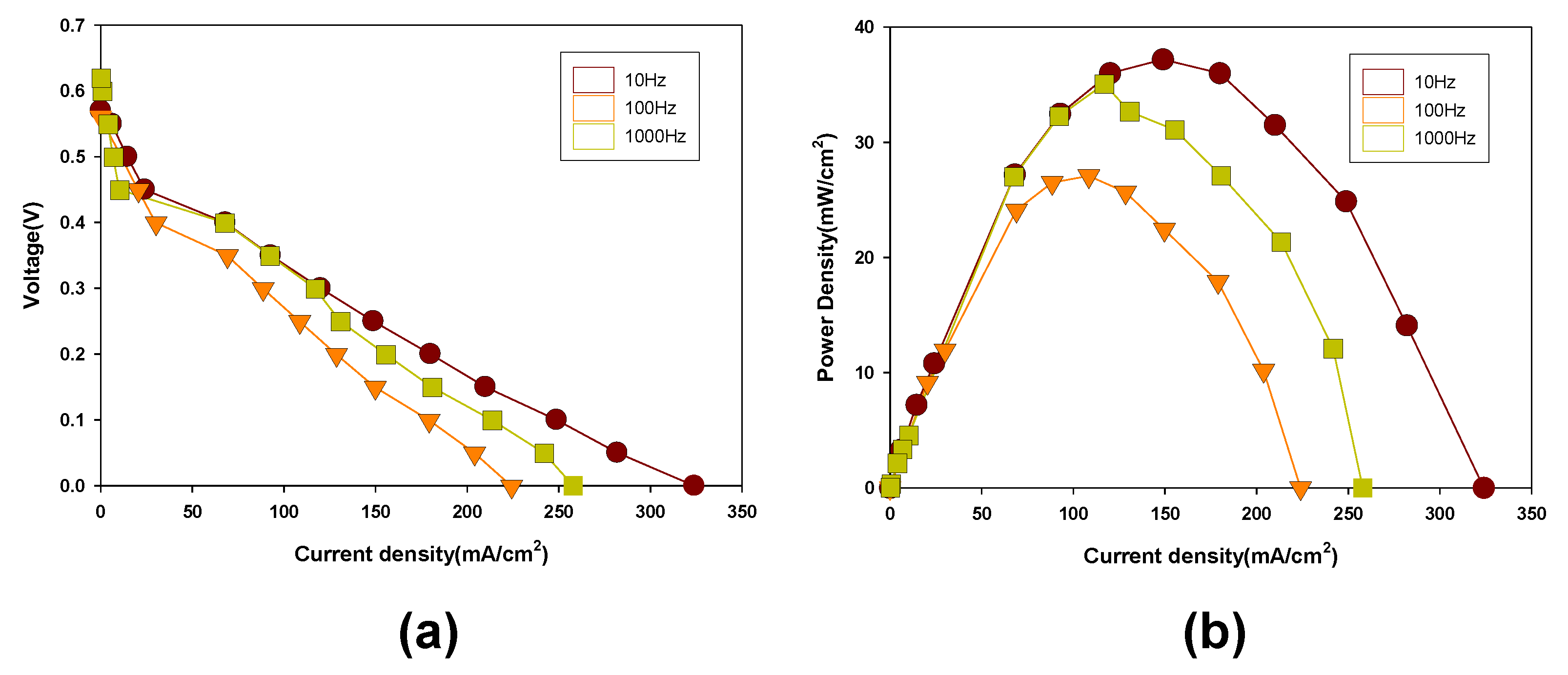
2.3. Operation and Performance Test of Micro DMFCs
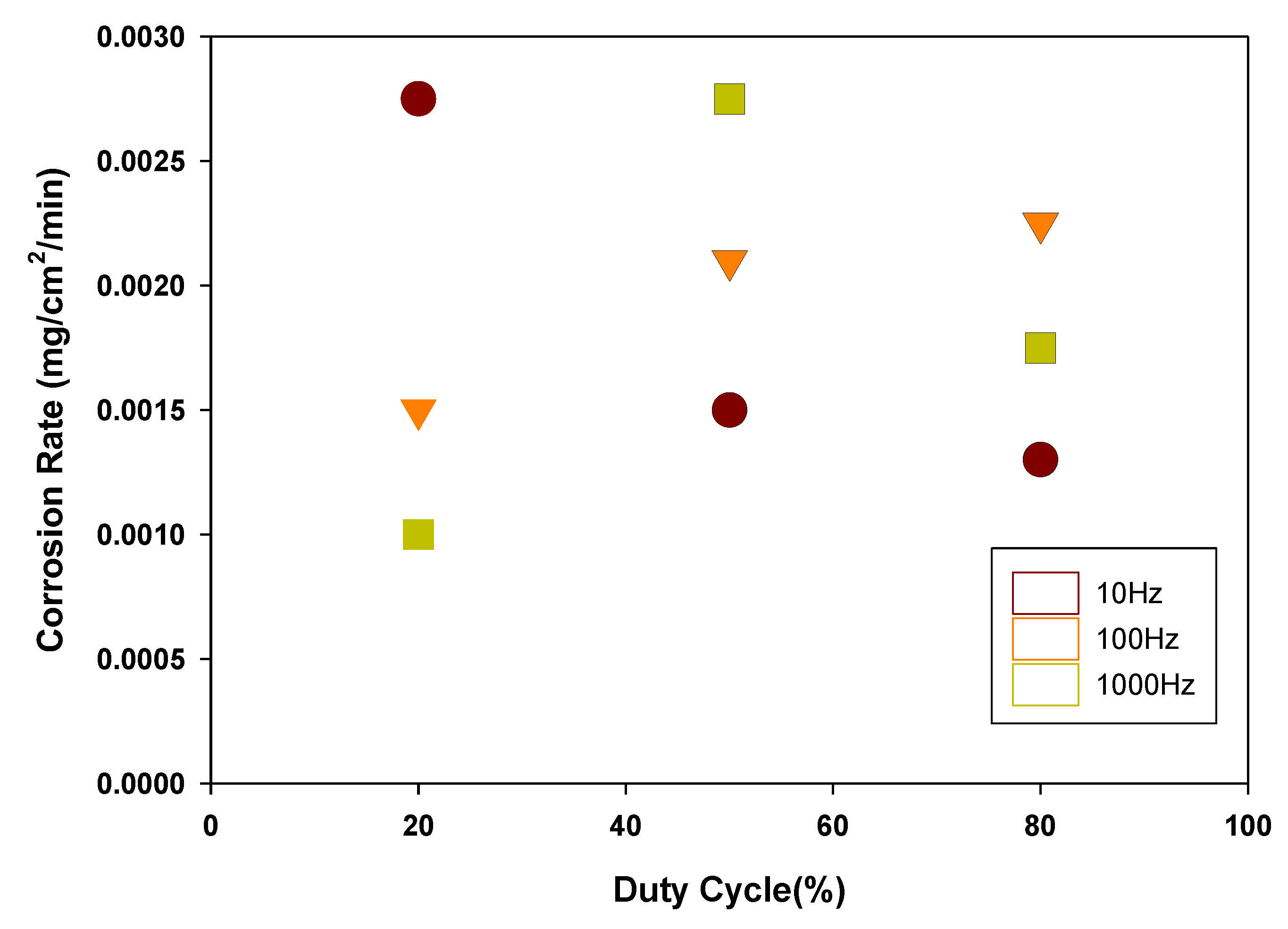
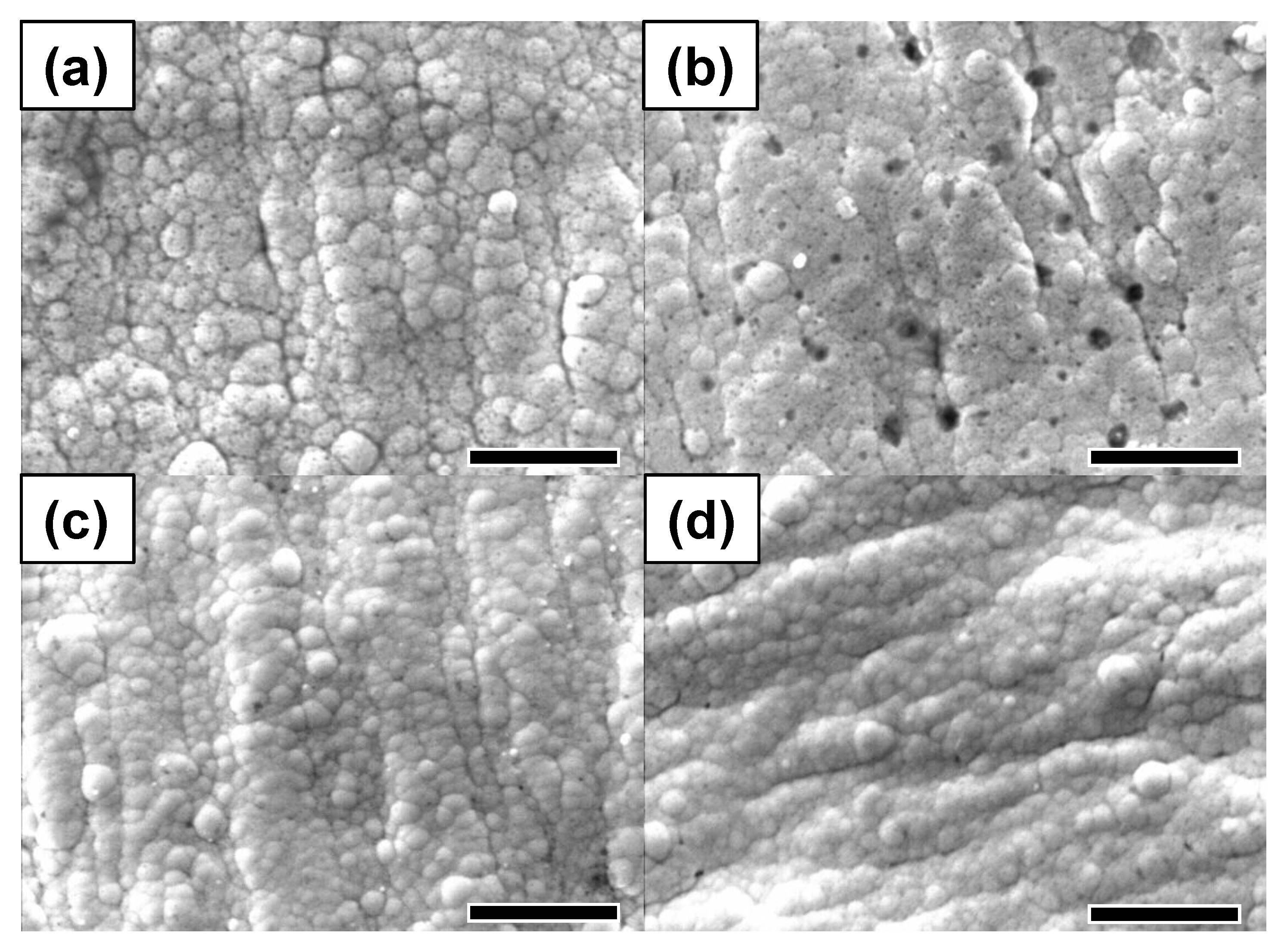
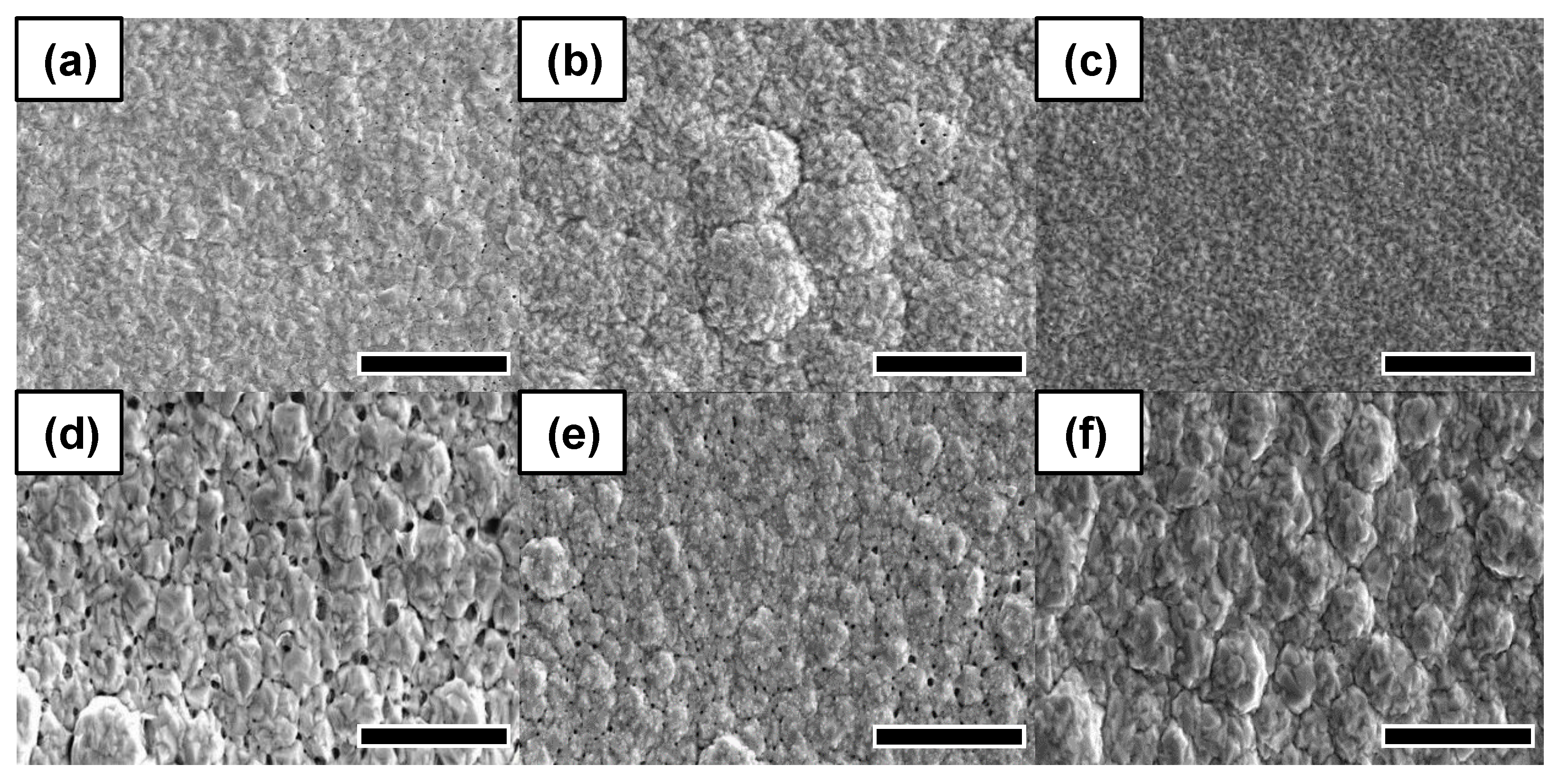
3. Results
4. Conclusions
Author Contributions
Funding
Acknowledgments
Conflicts of Interest
References
- Wang, Y.; Ruiz Diaz, D.F.; Chen, K.S.; Wang, Z.; Adroher, X.C. Materials, technological status, and fundamentals of PEM fuel cells—A review. Mater. Today 2020, 32, 178–203. [Google Scholar] [CrossRef]
- Staffell, I.; Scamman, D.; Velazquez Abad, A.; Balcombe, P.; Dodds, P.E.; Ekins, P.; Shah, N.; Ward, K.R. The role of hydrogen and fuel cells in the global energy system. Energy Environ. Sci. 2019, 12, 463–491. [Google Scholar] [CrossRef] [Green Version]
- Munjewar, S.S.; Thombre, S.B.; Mallick, R.K. Approaches to overcome the barrier issues of passive direct methanol fuel cell–Review. Renew. Sustain. Energy Rev. 2017, 67, 1087–1104. [Google Scholar] [CrossRef]
- Munjewar, S.S.; Thombre, S.B.; Mallick, R.K. A comprehensive review on recent material development of passive direct methanol fuel cell. Ionics 2017, 23, 1–18. [Google Scholar] [CrossRef]
- Junoh, H.; Jaafar, J.; Nik Abdul, N.A.H.; Ismail, A.F.; Othman, M.H.D.; Rahman, M.A.; Aziz, F.; Yusof, N. Performance of polymer electrolyte membrane for direct methanol fuel cell application: Perspective on morphological structure. Membranes 2020, 10, 34. [Google Scholar] [CrossRef] [Green Version]
- Fang, S.; Zhang, Y.; Zou, Y.; Sang, S.; Liu, X. Structural design and analysis of a passive DMFC supplied with concentrated methanol solution. Energy 2017, 128, 50–61. [Google Scholar] [CrossRef]
- Raj, V. 16-Direct methanol fuel cells in portable applications: Materials, designs, operating parameters, and practical steps toward commercialization. In Direct Methanol Fuel Cell Technology; Dutta, K., Ed.; Elsevier: Amsterdam, The Netherlands, 2020; pp. 495–525. ISBN 978-0-12-819158-3. [Google Scholar]
- Braz, B.A.; Moreira, C.S.; Oliveira, V.B.; Pinto, A.M.F.R. Effect of the current collector design on the performance of a passive direct methanol fuel cell. Electrochim. Acta 2019, 300, 306–315. [Google Scholar] [CrossRef]
- Wang, L.; He, M.; Hu, Y.; Zhang, Y.; Liu, X.; Wang, G. A “4-cell” modular passive DMFC (direct methanol fuel cell) stack forportable applications. Energy 2015, 82, 229–235. [Google Scholar] [CrossRef]
- Barbera, O.; Stassi, A.; Sebastian, D.; Bonde, J.L.; Giacoppo, G.; D’Urso, C.; Baglio, V.; Aricò, A.S. Simple and functional direct methanol fuel cell stack designs for application in portable and auxiliary power units. Int. J. Hydrogen Energy 2016, 41, 12320–12329. [Google Scholar] [CrossRef]
- Hong, P.; Liao, S.; Zeng, J.; Huang, X. Design, fabrication and performance evaluation of a miniature air breathing direct formic acid fuel cell based on printed circuit board technology. J. Power Sources 2010, 195, 7332–7337. [Google Scholar] [CrossRef]
- Sundarrajan, S.; Allakhverdiev, S.I.; Ramakrishna, S. Progress and perspectives in micro direct methanol fuel cell. Int. J. Hydrogen Energy 2012, 37, 8765–8786. [Google Scholar] [CrossRef]
- Lee, Y.H.; Noh, S.T.; Lee, J.H.; Chun, S.H.; Cha, S.W.; Chang, I. Durable graphene-coated bipolar plates for polymer electrolyte fuel cells. Int. J. Hydrogen Energy 2017, 42, 27350–27353. [Google Scholar] [CrossRef]
- Yuan, Z.; Zhang, Y.; Leng, J.; Zhao, Y.; Liu, X. Performance of air-breathing direct methanol fuel cell with Au-coated aluminum current collectors. Int. J. Hydrogen Energy 2012, 37, 2571–2578. [Google Scholar] [CrossRef]
- Sabaté, N.; Esquivel, J.P.; Santander, J.; Hauer, J.G.; Verjulio, R.W.; Gràcia, I.; Salleras, M.; Calaza, C.; Figueras, E.; Cané, C.; et al. New approach for batch microfabrication of silicon-based micro fuel cells. Microsyst. Technol. 2014, 20, 341–348. [Google Scholar] [CrossRef]
- Giurlani, W.; Zangari, G.; Gambinossi, F.; Passaponti, M.; Salvietti, E.; Di Benedetto, F.; Caporali, S.; Innocenti, M. Electroplating for decorative applications: Recent trends in research and development. Coatings 2018, 8, 260. [Google Scholar] [CrossRef] [Green Version]
- Ye, F.; Wang, Z.; Xu, C.; Yuan, M.; Liu, P.; Yang, W.; Liu, G. Mechanism and kinetic study of pulse electrodeposition process of Pt/C catalysts for fuel cells. Renew. Energy 2020, 145, 514–520. [Google Scholar] [CrossRef]
- Chandrasekar, M.S.; Pushpavanam, M. Pulse and pulse reverse plating-Conceptual, advantages and applications. Electrochim. Acta 2008, 53, 3313–3322. [Google Scholar] [CrossRef]
- Arunsunai Kumar, K.; Paruthimal Kalaignan, G.; Muralidharan, V.S. Direct and pulse current electrodeposition of Ni-W-TiO2 nanocomposite coatings. Ceram. Int. 2013, 39, 2827–2834. [Google Scholar] [CrossRef]
- Dilasari, B.; Jung, Y.; Kwon, K. Comparative study of corrosion behavior of metals in protic and aprotic ionic liquids. Electrochem. Commun. 2016, 73, 20–23. [Google Scholar] [CrossRef]
- Luo, H.; Li, Z.; Mingers, A.M.; Raabe, D. Corrosion behavior of an equiatomic CoCrFeMnNi high-entropy alloy compared with 304 stainless steel in sulfuric acid solution. Corros. Sci. 2018, 134, 131–139. [Google Scholar] [CrossRef]
- Długołecki, P.; Ogonowski, P.; Metz, S.J.; Saakes, M.; Nijmeijer, K.; Wessling, M. On the resistances of membrane, diffusion boundary layer and double layer in ion exchange membrane transport. J. Memb. Sci. 2010, 349, 369–379. [Google Scholar] [CrossRef]
- Yasuda, H.; Yu, Q.S.; Chen, M. Interfacial factors in corrosion protection: An EIS study of model systems. Prog. Org. Coat. 2001, 41, 273–279. [Google Scholar] [CrossRef]
- Chen, M.; Wang, M.; Yang, Z.; Ding, X.; Wang, X. Long-term degradation behaviors research on a direct methanol fuel cell with more than 3000h lifetime. Electrochim. Acta 2018, 282, 702–710. [Google Scholar] [CrossRef]


| Degreasing (ACL-009) | 25 °C, 3 min |
| Soft etching (Na2O8 and H2SO4) | 25 °C, 3 min |
| Pre-dipping (MSR-28P) | 25 °C, 1 min |
| Catalyst adsorption (MSR 28A) | 25 °C, 5 min |
| Accelerator (MSR 28B) | 25 °C, 5 min |
| Electroless nickel plating | 85 °C, 10 min |
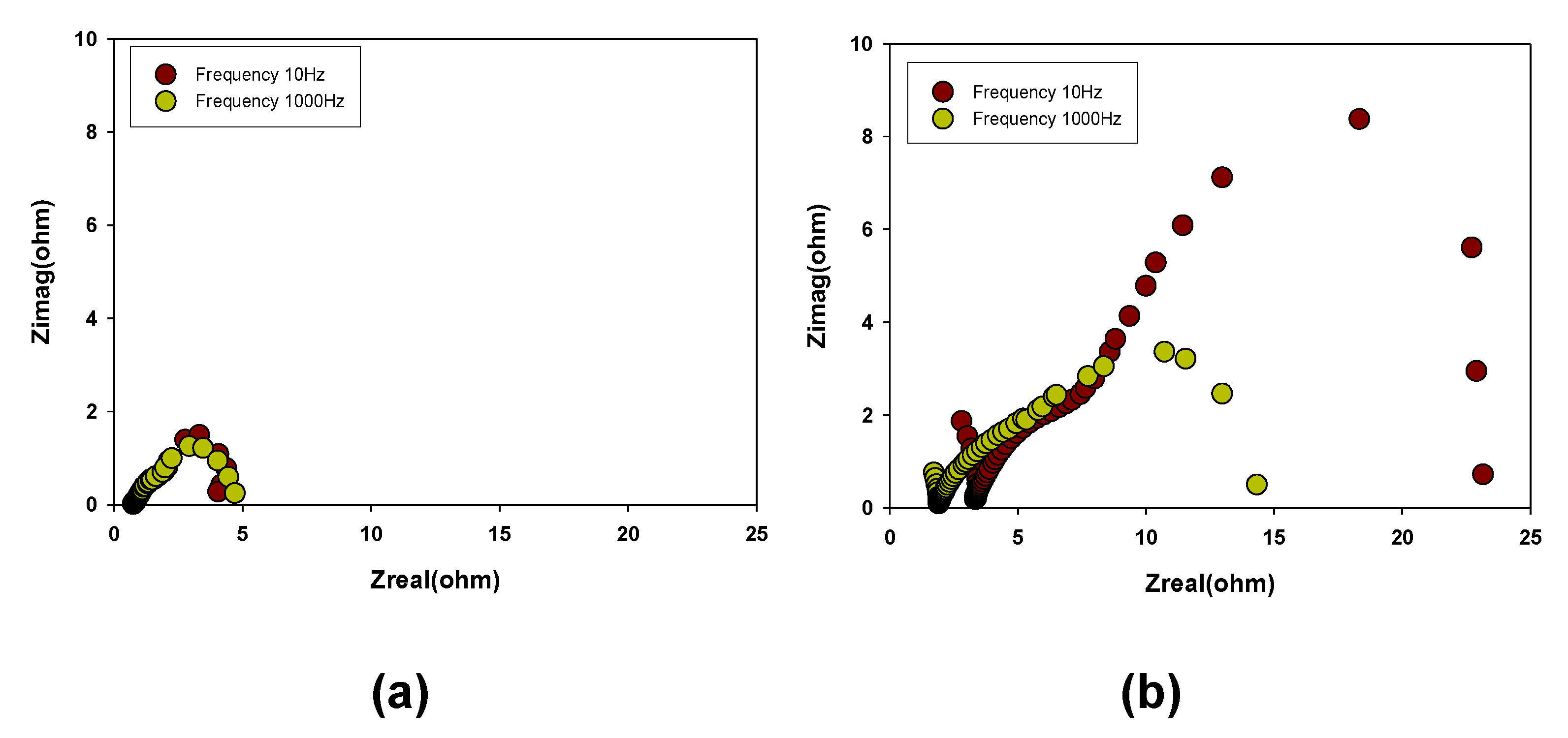
| 10 Hz (Initial) | 1 kHz (Initial) | 10 Hz (after) | 1 kHz (after) | |
|---|---|---|---|---|
| Rs (Ω) | 0.73 | 0.74 | 2.799 | 1.714 |
| Rct (Ω) | 3.949 | 3.316 | 20.354 | 12.613 |
Publisher’s Note: MDPI stays neutral with regard to jurisdictional claims in published maps and institutional affiliations. |
© 2021 by the authors. Licensee MDPI, Basel, Switzerland. This article is an open access article distributed under the terms and conditions of the Creative Commons Attribution (CC BY) license (https://creativecommons.org/licenses/by/4.0/).
Share and Cite
Park, S.-S.; Shin, N.-Y.; Lee, C.; Jeon, Y.; Chi, W.S.; Shul, Y.-G. Au Coated Printed Circuit Board Current Collectors Using a Pulse Electroplating Method for Fuel Cell Applications. Energies 2021, 14, 4960. https://doi.org/10.3390/en14164960
Park S-S, Shin N-Y, Lee C, Jeon Y, Chi WS, Shul Y-G. Au Coated Printed Circuit Board Current Collectors Using a Pulse Electroplating Method for Fuel Cell Applications. Energies. 2021; 14(16):4960. https://doi.org/10.3390/en14164960
Chicago/Turabian StylePark, Sang-Sun, Na-Young Shin, Chanmin Lee, Yukwon Jeon, Won Seok Chi, and Yong-Gun Shul. 2021. "Au Coated Printed Circuit Board Current Collectors Using a Pulse Electroplating Method for Fuel Cell Applications" Energies 14, no. 16: 4960. https://doi.org/10.3390/en14164960
APA StylePark, S.-S., Shin, N.-Y., Lee, C., Jeon, Y., Chi, W. S., & Shul, Y.-G. (2021). Au Coated Printed Circuit Board Current Collectors Using a Pulse Electroplating Method for Fuel Cell Applications. Energies, 14(16), 4960. https://doi.org/10.3390/en14164960