Article

Structure Optimization of a High-Temperature Oxygen-Membrane Module Using Finite Element Analysis

1
School of Mechanical Engineering, Chung-Ang University, 221 Heukseok-Dong, Dongjak-Gu, Seoul 156-756, Korea
2
Center for Defense Resource Management, Korea Institute for Defense Analyses, 37, Hoegi-ro, Dongdaemun-gu, Seoul 02455, Korea
3
Energy Materials Laboratory, Korea Institute of Energy Research, Jang-dong 71-2, Daejeon 305-343, Korea
*
Author to whom correspondence should be addressed.
Energies 2021, 14(16), 4992; https://doi.org/10.3390/en14164992
Submission received: 18 July 2021 / Revised: 1 August 2021 / Accepted: 11 August 2021 / Published: 14 August 2021
(This article belongs to the Special Issue Application of Composite Materials for Energy Devices)

Abstract

:
The oxygen transport membrane (OTM) is a high-density ion-conducting ceramic membrane that selectively transfers oxygen ions and electrons through the pressure differential across its layers. It can operate at more than 800 °C and serves as an economical method for gas separation. However, it is difficult to predict the material properties of the OTM through experiments or analyses because its structure contains pores and depends on the characteristics of the ceramic composite. In addition, the transmittance of porous ceramic materials fluctuates strongly owing to their irregular structure and arbitrary shape, making it difficult to design such materials using conventional methods. This study analyzes the structural weakness of an OTM using CAE software (ANSYS Inc., Pittsburgh, PA, USA). To enhance the structural strength, a structurally optimized design of the OTM was proposed by identifying the relevant geometric parameters.

1. Introduction

Oxygen Transport Membrane

An oxygen transport membrane (OTM) is an ion-conducting membrane that selectively transports oxygen via the pressure difference between its two sides. The OTM is an economical component used in gas separation methods [1,2,3,4,5,6,7,8].
Ceramic membranes with mixed conductivity transport both ions and electrons. These membranes can separate oxygen without requiring external energy or applied voltages, as the electrons travels in or against the direction of the oxygen ions [9,10,11,12,13,14,15,16].
Oxygen ions migrate through the porous lattice when the lattice vibrates at more than 800 °C. OTMs exhibit feeble lattice vibrations at low temperatures. Pure OTMs operate at high temperatures and pressures; therefore, they necessitate mechanical, thermal, and structural stability. When a ceramic membrane is exposed to high temperatures and pressures, it disintegrates. To protect such membranes and maximize their efficiency, researchers have developed various types of laminated forms and module systems.
In laminated forms, each layer must have a specific functional characteristic. For example, the membrane layer must have structural stability to endure external pressures and osmosis; the porous layer must have a microstructure to transport oxygen ions; the catalyst, chemical stability; and the support layer must have mechanical, thermal, and chemical stability. Additionally, if the structure shown in Figure 1 acts as the membrane assembly, then it would require sealing methods to allay external particles, and it must possess mechanical durability [17].
Module systems including the plate-, hollow [18], and honeycomb-type membrane modules (Figure 2) have been developed [19]. These systems must have a high effective cross-sectional area, relative to the membrane-response area, for ease of manufacturing and to ensure complete sealing.
In the late 1980s, the US, Japan, Europe, and other countries acknowledged the importance of high-oxygen separation techniques [20] and invested substantially in related studies. The Korea Institute of Energy Research has been conducting research on ion-conductive membrane processes. OTM conductors can be fabricated by selectively separating high concentrations of oxygen, regardless of the size. Therefore, these conductors are gradually being expanded to steelmaking, automotive, and manufacturing industries [21].
The research on composite ceramic or porous ceramic OTMs and OTM modules can be classified into six subjects as shown in Figure 3:
  • Membrane material, which covers the characteristics of the membrane along with its structure, composition, and production process [1,17,18,19,20,21,22,23,24,25,26,27,28,29,30,31,32,33,34,35,36,37,38,39,40,41,42,43,44,45,46,47,48,49,50].
  • Composite ceramic characteristics, structures, and mechanical behaviors [4,32,34,51,52,53,54].
  • OTM systems, which include the lifetime and fatigue failure predictions at high temperatures and pressures [55,56].
  • Pure material experiments [5,57], which theoretically and experimentally investigate the material properties at high temperatures and pressures, structure of mixed materials, and mixed compositions [51,58].
  • Computer simulation, which is used to analyze the weak points in the membrane, predict the stresses in the OTM module system, and optimize or verify production [53,57,59,60,61,62,63,64,65,66,67,68,69,70,71,72,73,74,75,76]. Although a few researchers have studied hollow and tubular modules, limited research has been devoted toward plate-type modules.
  • The latest research trends and applications of composite ceramics and OTM systems [77,78,79,80,81,82,83,84].

2. Structural Analysis of OTM Modules

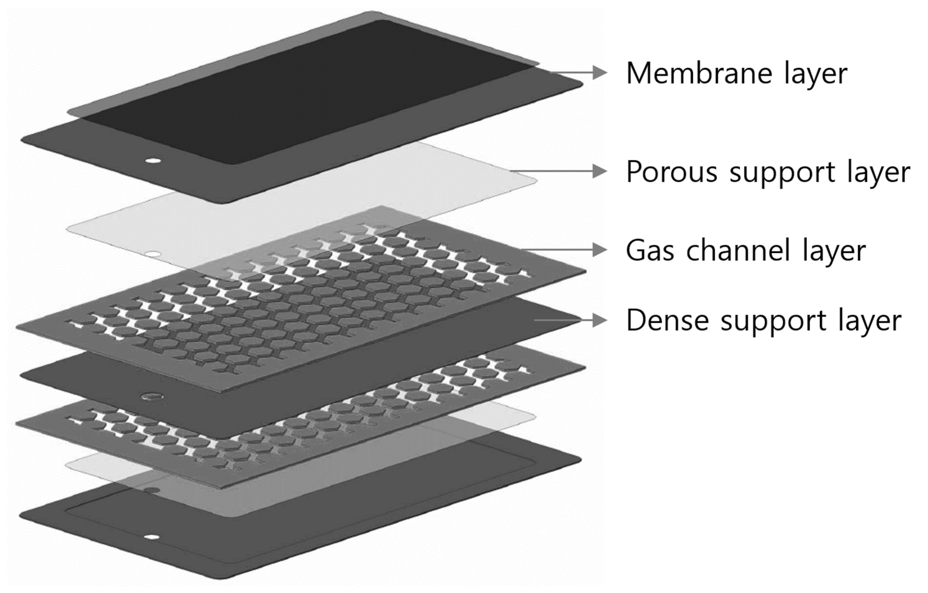
2.1. Model Description

OTMs should possess mechanical, thermal, and structural stability because the OTM modules must selectively permeate oxygen via ion conduction, which is only possible at high temperatures (more than 800 °C) and pressures (more than 10 bar). The membrane is only 10–100 µm thick, and therefore it is vulnerable to external conditions.
However, enhancing the membrane’s structural stability by simply increasing the membrane thickness would make the penetration ratio impractically low. Therefore, researchers are experimenting with various module shapes that can compensate for the thickness, to ensure that the membrane is protected without losing its features. The addition of porous ceramics that permeate oxygen around the membrane to stabilize the structure opens the possibility of a variety of module systems. As mentioned earlier, the OTM must be impermeable, thermally and structurally stable, and easy to produce, while possessing a high cross-sectional area of effective penetration relative to the response volume.
The plate-type module used in previous studies [45,47] was modified and used as the basis for the OTM module shape in this study (Figure 4).
The components of the module were organized into a single sealed form, which consists of a membrane layer (OTM), a porous layer (permeability support layer), a gas-channel layer (pure oxygen gas passing layer), and a dance support layer (impermeable support layer).
The area and diffusion rate of the ceramic membrane cannot be disclosed as it is a proprietary technology of the Korea Institute of Energy Research. However, the thickness of the layer and the stacking order have been disclosed.
In collaboration with the institution, the membrane was designed with a high penetration ratio and structural stability. Table 1 provides information on the material composition and the thickness of each layer. Figure 5 and Figure 6 illustrates the components of the OTM module. As seen in the figure, each unit is a vertically symmetrical layered structure.

2.2. Simulation Suite

The structure of the OTM module was analyzed using commercial finite element analysis software and modeled on Catia V5.0 (ANSYS Workbench Design Modeler, ANSYS Inc., Pittsburgh, PA, USA) after defining the composition of each layer as a set, based on the specifications mentioned earlier. This module was prepared as a set concept through the sintering process after each layer was prepared, and all the layers were laminated.
Each layer in ANSYS Workbench consisted of a solid, and the above models were assembled to form parts. The symmetry condition was used to reduce the computational time, which allowed expressing only half of the OTM module set in ANSYS. The material properties of each layer were obtained using the data from the material experiments, as detailed in Table 1 of [85].
The boundary conditions of the model were as follows:
  • An internal pressure of 10 kPa was applied because the 1 MPa gas-channel layer of the external pressure can extract oxygen via the pressure difference between the internal and external surfaces.
  • Each layer was laminated to constitute a unit. Thus, symmetric conditions were applied to the top face of the membrane layer and the bottom face of the gas-channel layer via the entire structure of all the laminated units.
  • In view of the half model, the surroundings of the side with the hole were assigned the left-symmetry right-symmetry condition.
Part of the high-stress concentration appears between the porous and gas-channel layers, which represents the pressure differential across the OTM module.
It was essential to choose the element formation because the thickness of the generated element is in the micrometer range, owing to the thin membrane of the OTM and the difference in the stress values in accordance with the formation of the membrane and the size of the lattice for the element generating.
Element generation or meshing is an important step in the finite element method. Omitting this step or using the auto-mesh function can produce critical errors in the analysis. To enhance the accuracy, the type, number, and distribution of finite elements must be meticulously selected according to the analysis model and type. The area and space of the detailed structure and the region of stress concentration and gradient fluctuations require detailed grid separation and additional mesh convergence tests after the analysis.
The number of grid layers according to each layer and the element size of the total OTM model were used as the parameters for the mesh convergence test (Figure 7 and Figure 8).
For the grids, using the eight-node hexahedral element would have led to a local stress concentration and the accuracy of the stress values with the form of the gas-channel layer. As the number of stacked elements per OTM module layer increases, the computational time and the number of elements increase. To precisely express the stress gradient section due to the material difference of each layer and to increase the accuracy of the analysis of the thin-membrane OTM module, we chose the three-dimensional 20-node hexahedral element.
The OTM unit model had an element size of 100 μm. The mesh layer with five layers toward the thickness of each layer forms the grid model. There were approximately 500,000 elements and 2,000,000 nodes.

2.3. Result

Two vulnerable regions were identified on the OTM module: the neighborhood of the support structures between the porous layer and the gas-channel layer with large membrane stress and pressure differences; and a processing hole. Figure 9, Figure 10 and Figure 11 illustrate the results of the structural analysis for each layer. The membrane layer had a stress distribution less than the breaking strength (58.5 MPa). The maximum stress (35 MPa) around the processing hole was also less than the breaking strength. In the porous layer, the stress (95 MPa) was significantly higher than the breaking strength (44.6 MPa). This region of high stress was in contact with the gas-channel support layer with a significant pressure difference.
Therefore, the peripheral region of the porous layer must be designed as a support structure to account for the high stress around the region adjacent to the high-stress region on the porous layer of the gas-channel layer.
A detailed model must be constructed instead of a half model to perform a complete structural analysis and observe the weak points in the structure. Therefore, we defined a section model (Figure 12) by slicing a few sections from the half model.
The section model was assigned the same boundary conditions and grid compositions as the half model. In the analysis, a symmetric boundary condition was applied to the top and bottom of the model because a few sections were extracted as shown in Figure 12. The results of the structural analysis of each layer in the section model are presented in Figure 13, Figure 14 and Figure 15 and Table 2, Table 3 and Table 4.
The detailed structural analysis revealed that the membrane layer of the section model had a lower maximum stress than the half model. The stress contour was reconstructed, considering that the machining hole was removed. Subsequently, the region except the machining hole was confirmed as having the same stress distribution as the half model. The same stresses as in the half model were observed in the porous layer sections. The region of high stress was adjacent to a supporting layer of the gas-channel layer with the pressure difference, which was the same as in the half model. Additionally, the stress of the gas-channel layer was higher in the peripheral region supporting the porous layer in the section model, as compared to that in the half model.
To summarize, the design of the applied area must be modified to account for the high stress observed in the area with the pressure gradient, i.e., the point where the porous layer and gas-channel layer come in contact, and to prevent failure. This stress exceeded the breaking strength. However, the membrane layer, which had a stress lower than the breaking strength (58.5 MPa), did not require a design change because the structure would not fail and was safer than the other layers.
The structural analyses of the half model and the section model revealed the fragile and high-stress regions in the membrane, respectively. The boundary between the porous and the gas-channel layers, where the pressure gradient was significant, was the fragile region.
A more detailed observation of the section model confirmed that the weak point was the area connecting the gas-channel support and the porous layer.
To compensate for the weak point, the stress must be reduced by modifying the geometric design of the honeycomb base support of the gas-channel layer and the width of the gas channel. A design supplement must be recommended through additional structural analyses by setting the parameters with these causes. The parametric and structural optimization studies are explained in Section 3.
According to previous research, the most optimal method of reducing stress for structural stability is to increase each layer’s thickness. However, as mentioned earlier, this approach would reduce the penetration ratio.
Therefore, to retain the original penetration ratio of the OTM module, we omit thickness as a parameter in the parametric and optimization studies. Further details of this tradeoff are provided in the Limitations section of Section 3.

3. Structure Optimization of OTM Module

3.1. Model Description

The structural analysis results of the OTM module suggest using the shape of the gas-channel layer support (the length and apex round of the honeycomb structure) and the gas-flow channel as alternative parameters for the design supplement of the OTM module.
However, using the applied variables in the model and analyzing the structure of every geometric shape in each case is computationally taxing.
Therefore, we conducted the parametric study by reducing the computational time as a design supplement and using the ANSYS Workbench optimization program to suggest the optimal specifications of the OTM module.
For the structural optimization, the response surface of each parameter was established and the design variables and objective function were set. To expedite the process, a unit model was chosen by compressing the models. The length (L) and apex round of the honeycomb (R) and the width of the flow channel (W) were chosen as the input design variables. The equivalent stresses of the membrane, porous layers, and entire module were selected as the objective functions.
The response-surface method (or the response-surface analytical method) was used for the optimization. This method is used to optimize the level of a variable by helping to expect the result values of the unselective level of the total area of interest, and thus achieve the desired value.
This makes the changing estimation by a variable appear in a two- or three-dimensional space, which is a dot on a flat or curved surface. It must be performed to determine and optimize the maximum and minimum on the surface. The line or surface on which the optimal conditions pass is defined as the response surface. Theoretically, higher the number of parameter cases, greater is the analytical load in the response-surface method. However, the computational load is limited by the computer hardware. This will subsequently reduce the accuracy of the response curve surfaces or lines. Therefore, the response-surface method, which is an experimental method for the selection of parametric variables, was used for the analysis of the minimum.

3.2. Simulaton Setup

We used the following variables in the ANSYS Workbench Design Modeler: Honeycomb structure length = L, Honeycomb vertex round = R, and Gas channel width = W.
The design variable was set as an input variable, which is expressed as a unit model in Figure 16. The material data from Table 1 of ref [85] were input as the material properties.
Each layer was formed by five grids in the thickness direction based on the mesh convergence test results using a 20-node hexagonal three-dimensional element. The overall element size was 50 μm, and detailed element information is provided below. The number of elements was approximately 200,000 and the number of nodes was approximately 700,000.
We established the symmetric conditions as the boundary conditions in all directions of the unit model (Figure 17).
The pressure conditions involved an external pressure of 1 MPa and an internal pressure of 10 kPa (Figure 18).
The maximum equivalent stress of the membrane layer, which governs the function of an OTM module; the porous layer designated as a vulnerable area based on the structural analysis; and the maximum equivalent stress of the entire module, including the region where a stress change was expected along with a shape change, according to the geometric design safety parameters, were selected as the objective functions.
Additionally, induction variables (variables generated using the input variables or design variables and numerical combinations of the objective variables) were adopted.
The effective area through which oxygen ions permeate is defined as the active area. The total area of the OTM module is defined as the total area. The ratio of the effective area to the total module area is called the effective area ratio. These are the induction variables.
The conditions for increasing the cross-sectional area of effective permeability per reaction volume of the membrane module were selected by introducing the concept of the final objective-function variable being the equivalent stress/effective area ratio of the membrane layer (Figure 19 and Figure 20).
The structure was optimized based on these conditions. In general, the parametric study is performed based on a method chosen to determine the total number of parameter cases in the experimental design stage.
In this parametric study, we chose 100 cases by introducing an additional sampling technique because the central synthesis method used three design variables and only 15 cases among the selected experimental design methods.
Despite the increased computational time, the method offers several advantages. For example, it allows for the generation of a reaction surface with a more accurate slope as it has a greater number of parameter design points, and the relationship between the response variables becomes narrower. Moreover, it reduces both the errors in the solution of the optimized variables and the result of the actual structural analysis. The structure was optimized to analyze the impact of each parameter, create a response surface, and propose an optimal OTM module design that satisfies the objective function.
The final objectives are:
  • Minimization of the maximum equivalent stress of the membrane layer/effective area ratio
  • Minimization of the maximum equivalent stress of the membrane layer
  • Maximization of the effective area ratio
  • Minimization of the maximum equivalent stress of the porous layer
  • Minimization of the maximum von Mises stress in the entire OTM module.

3.3. Result

This simulation result can be compared to the width of the flow path, which had the most significant effect on the stress in the OTM module. However, when the width was reduced to lessen the stress, it reduced the effective area of oxygen permeation. Therefore, these objective functions are not conducive to the optimization.
Figure 21, Figure 22, Figure 23, Figure 24 and Figure 25 illustrate the influences of the parameters and the response surface curvatures for the 100 cases with the chosen experimental design method and the additional sampling technique. The minimum points of the honeycomb width and apex round were observed. However, as the width of the channel decreased, the stress also decreased, and vice versa. To set the width of the flow path as the optimal design variable, the final objective function was optimized by applying 1.5 times the weight to the maximization of the effective area ratio.
Figure 23 depicts the local sensitivity of each parameter. The design parameter with the greatest effect on the maximum stress of the OTM module is the width of the flow path. The effective permeable area is determined by the widths of the honeycomb and the flow path. However, considering the membrane’s maximum stress/effective permeability area ratio as the final objective function of this optimization, L was identified as the most sensitive variable.
The structural analysis enabled the selection of the minimum values on the reaction surface curves per parameter. The membrane stress (21 MPa) was less than the allowable stress (58.5 MPa); however, the stress (78.3 MPa) at the porous support–gas layer interface was confirmed to be higher than the minimum allowable stress (32 MPa).
Therefore, the optimization analysis was repeated by adding the fracture stress of each layer to the objective function, as follows:
  • Minimization of the maximum equivalent stress of the membrane layer to less than 58.5 MPa.
  • Minimization of the maximum equivalent stress of the porous layer to less than 32 MPa.
  • Minimization of the maximum equivalent stress/effective area ratio of the membrane layer.
  • Maximization of the effective area ratio.
  • Minimization of the maximum von Mises stress in the entire OTM module.
Figure 26 and Figure 27 illustrates the results of the second optimization analysis based on the reset objective function. The results show that the brittle stress of the porous support layer mentioned in Section 2 was 30 MPa, which was less than the breaking stress (32 MPa). The brittle stress of the membrane layer was 16.2 MPa, which was less than the minimum breaking stress of 58.5 MPa.
Based on these results, we proposed a design method to stabilize the structure of the plate-type OTM module. The porous layer was confirmed to be the weakest part of the OTM module, which agrees with the observations of a previous study [67]. To structurally stabilize the OTM module, the geometry of the gas-channel layer and the width of the gas channel were changed without increasing the thickness of each layer of the OTM module. This could reduce the stress of the porous layer. Based on the structural stability, this study proposed a design method to achieve an effective permeable cross-sectional area ratio of the OTM module.

4. Discussion

4.1. General Discussion

The application of porous composite ceramics has been expanded to various fields. The material properties of these ceramics must be obtained and their characteristics must be predicted because their mechanical properties change with the pore size, porosity, and microstructure.
In addition, the material properties of specimens are significantly different from the stiffness and strength distributions of other materials. This implies that there exists a significant difference between the material properties of each specimen. Several studies have proven that this is due to differences in the pore microstructures [85].
We confirmed that the point in the OTM module at which the maximum stress is generated lies on the porous layer, i.e., this layer is the weakest point in the module. Studies have suggested increasing the thickness of the porous layer to compensate for its structural weakness. This approach could overcome the structural weakness, but it eventually returns to its vulnerable state because of the relatively low oxygen permeability in thick layers, which warrants the application of higher external pressures.
Therefore, we selected the geometric shape parameters of the support structure of the gas-channel layer (and not the porous layer) and the width of the gas channel as the design variables and optimized it without increasing the thickness of the porous layer.
The objective function of a typical optimization procedure is to minimize the maximum stress value among the fragile structural parts or in the overall model. However, if the design variables and input variables for the optimization are proportional to the objective function, or if the input variables are also selected via objective function minimization, the results may not converge or the process may yield incorrect results. Therefore, the correct objective function must be selected by observing the influence of the design variables and the response curves before performing the optimization.
In this study, increasing the effective permeable cross-section relative to the reaction area of the membrane module, which was the priority of the OTM module design, was selected as the final objective function. Moreover, the proposed approach eliminated the need for further parametric studies proportional to the input and objective function. The results demonstrated an effective oxygen permeable area ratio and paved the way for an optimal, structurally stable OTM module design.

4.2. Limitations

The structural analysis results presented in Section 3 do not include the effect of flow analysis results. Simulation studies on OTM membranes reveal the porous layer or porous support as the vulnerable component of the membrane. The studies suggested increasing the thickness of the porous layer to enhance the structural strength and stabilize the structure. However, this reduces the oxygen transmission rate. Further verification of oxygen permeability is required to solve this problem. Studies have attempted to replace the verification with flow analysis. In this study, the structural strength was enhanced through structural analysis, without increasing the thickness and affecting the oxygen permeability. Additionally, the optimal structural design of an OTM membrane module was determined by selecting the parameters that influence the geometrical shape of the weak region to stabilize the structure.
The current structural optimization design technique determines the optimal values of design variables that satisfy the objective functions and design constraints defined for a given physical condition, using a structural analysis program based on mathematical theory. Recent studies have designed optimal structures by treating not only the dimensions and geometric shapes but also the topology and material compositions as design variables. Several studies have developed optimization programs that couple multiphysics. These programs require a significant amount of time to analyze each physical system and implement the results in a complex system, in addition to verifications. Therefore, to propose an optimal design for the OTM module, we replaced the flow effect with structural optimization analysis through the constraint function, which maintains oxygen permeability.
However, the reliability of the OTM module can be further improved. Recent multiphysics optimization programs that effectively interpret multiphysics systems are now bundled with commercial software. Structural optimization analyses that consider the flow–structure interaction could identify problems not covered in this study. The results could help modify and supplement the proposed design, albeit at a longer computational time.

5. Conclusions

We analyzed the structure of a modified plate-type OTM module composed of a composite ceramic material with a porous layer. A whole model, a half model, and a section model were analyzed to obtain a comprehensive profile. The results confirmed the porous layer to be the most vulnerable part of the module because of the external–internal pressure gradient and the difference of material properties between the porous layer and the gas-channel layer. To retain the oxygen permeability and oxygen permeation area ratio of the OTM module, the porous layer thickness and the oxygen permeation area of the gas-channel layer were not changed. To enhance the structural stability, the structures were optimized by introducing a design parameter that changed the geometrical shape around the region with the maximum stress. Based on the results, the final design of the OTM module was proposed.
The results of this study can be used to supplement the design of the region around the porous layer and promote structural stability.
Future studies must consider the effect of flow to confirm the inverse relationship between the thickness and transmittance of the porous layer, which has the most considerable influence on the actual transmittance. Therefore, the permeability and structural stability of the porous layer must be enhanced through an optimization program that couples a multiphysics system with the flow simulation of the OTM module. The final design recommended in this study must be experimentally validated.

Author Contributions

D.G.L. and S.-H.K. made a concept of device and simulation; D.G.L. conceived and designed the simulations; D.G.L. performed the simulations; D.G.L., J.W.N. and S.W.C. analyzed the data; D.G.L., J.W.N. and S.W.C. wrote the paper. All authors have read and agreed to the published version of the manuscript.

Funding

This research was funded by the Basic Science Research Program through the National Research Foundation of Korea (NRF) funded by the Ministry of Education (No. 2018R1D1A1A09084287) and by the research and development program of the Korea Institute of Energy Research (B8-2415-03).

Institutional Review Board Statement

The study was conducted according to the guidelines of the Declaration of Korea, and approved by the Institutional Review Board of Chung-Ang University.

Informed Consent Statement

Informed consent was obtained from all subjects involved in the study.

Data Availability Statement

Not applicable.

Conflicts of Interest

The authors declare no conflict of interest.

References

  1. Baumann, S.; Meulenberg, W.A.; Buchkremer, H.P. Manufacturing strategies for asymmetric ceramic membranes for efficient separation of oxygen from air. J. Eur. Ceram. Soc. 2013, 33, 1251–1261. [Google Scholar] [CrossRef]
  2. Garcia-Fayos, J.; Vert, V.B.; Balaguer, M.; Solís, C.; Gaudillere, C.; Serra, J.M. Oxygen transport membranes in a biomass/coal combined strategy for reducing CO2 emissions: Permeation study of selected membranes under different CO2-rich atmospheres. Catal. Today 2015, 257, 221–228. [Google Scholar] [CrossRef]
  3. Häffelin, A.; Niedrig, C.; Wagner, S.F.; Baumann, S.; Meulenberg, W.A.; Ivers-Tiffée, E. Three-Dimensional Performance Model for Oxygen Transport Membranes. J. Electrochem. Soc. 2014, 161, F1409–F1415. [Google Scholar] [CrossRef] [Green Version]
  4. Kim, S.; Kim, S.H.; Lee, K.S.; Yu, J.H.; Seong, Y.-H.; Han, I.S. Mechanical properties of LSCF (La0.6Sr0.4Co0.2Fe0.8O3−δ)–GDC (Ce0.9Gd0.1O2−δ) for oxygen transport membranes. Ceram. Int. 2017, 43, 1916–1921. [Google Scholar] [CrossRef]
  5. Li, C.-F.; Zhong, S.-H. Study on application of membrane reactor in direct synthesis DMC from CO2 and CH3OH over Cu–KF/MgSiO catalyst. Catal. Today 2003, 82, 83–90. [Google Scholar] [CrossRef]
  6. Miachon, S.; Perez, V.; Crehan, G.; Torp, E.; Ræder, H.; Bredesen, R.; Dalmon, J.A. Comparison of a contactor catalytic membrane reactor with a conventional reactor: Example of wet air oxidation. Catal. Today 2003, 82, 75–81. [Google Scholar] [CrossRef]
  7. Niedrig, C.; Wagner, S.F.; Menesklou, W.; Baumann, S.; Ivers-Tiffée, E. Oxygen equilibration kinetics of mixed-conducting perovskites BSCF, LSCF, and PSCF at 900 °C determined by electrical conductivity relaxation. Solid State Ion. 2015, 283, 30–37. [Google Scholar] [CrossRef]
  8. Yang, W.; Liu, X.; Yue, X.; Jia, J.; Guo, S. Bamboo-like carbon nanotube/Fe3C nanoparticle hybrids and their highly efficient catalysis for oxygen reduction. J. Am. Chem. Soc. 2015, 137, 1436–1439. [Google Scholar] [CrossRef]
  9. Dyer, P.N.; Richards, R.E.; Russek, S.L.; Taylor, D.M. Ion transport membrane technology for oxygen separation and syngas production. Solid State Ion. 2000, 134, 21–33. [Google Scholar] [CrossRef]
  10. Euser, B.; Zhu, H.; Berger, J.R.; Lewinsohn, C.A.; Kee, R.J. Electrochemical-Mechanical Coupling in Composite Planar Structures that Integrate Flow Channels and Ion-Conducting Membranes. J. Electrochem. Soc. 2017, 164, F732–F739. [Google Scholar] [CrossRef]
  11. Gao, J.; Liu, X.; Peng, D.; Meng, G. Electrochemical behavior of Ln0.6Sr0.4Co0.2Fe0.8O3−δ (Ln = Ce, Gd, Sm, Dy) materials used as cathode of IT-SOFC. Catal. Today 2003, 82, 207–211. [Google Scholar] [CrossRef]
  12. Rahemi, R.; Li, D. Variation in electron work function with temperature and its effect on the Young’s modulus of metals. Scr. Mater. 2015, 99, 41–44. [Google Scholar] [CrossRef] [Green Version]
  13. Shemilt, J.E.; Stanway, C.L.; Williams, H.M. Effect of plastic forming on the conductivity of a samaria-doped ceria electrolyte. Solid State Ion. 2000, 134, 111–117. [Google Scholar] [CrossRef]
  14. Takamura, H.; Tuller, H.L. Ionic-conductivity-of-Gd2GaSbO7-Gd2Zr2O7-solid-solutions with structural disorder. Solid State Ion. 2000, 134, 67–73. [Google Scholar] [CrossRef]
  15. Tian, C.; Chan, S.-W. Ionic conductivities, sintering temperatures and microstructures of bulk ceramic CeO2 doped with Y2O3. Solid State Ion. 2000, 134, 89–102. [Google Scholar] [CrossRef]
  16. Whittingham, M.S. Insertion electrodes as SMART materials: The first 25 years and future promises. Solid State Ion. 2000, 134, 169–178. [Google Scholar] [CrossRef]
  17. Wang, L.; Murata, K.; Inaba, M. Production of pure hydrogen and more valuable hydrocarbons from ethane on a novel highly active catalyst system with a Pd-based membrane reactor. Catal. Today 2003, 82, 99–104. [Google Scholar] [CrossRef]
  18. Dahl, P.I.; Fontaine, M.-L.; Peters, T.; Mei, S.; Larring, Y.; Henriksen, P.P.; Bredesen, R. Development and testing of membrane materials and modules for high temperature air separation. Energy Procedia 2011, 4, 1243–1251. [Google Scholar] [CrossRef] [Green Version]
  19. Zhu, D.C.; Xu, X.Y.; Feng, S.J.; Liu, W.; Chen, C.S. La2NiO4 tubular membrane reactor for conversion of methane to syngas. Catal. Today 2003, 82, 151–156. [Google Scholar] [CrossRef]
  20. Sousa, J.M.; Mendes, A. Modeling a dense polymeric catalytic membrane reactor with plug flow pattern. Catal. Today 2003, 82, 241–254. [Google Scholar] [CrossRef]
  21. Schäfer, R.; Noack, M.; Kölsch, P.; Stöhr, M.; Caro, J. Comparison of different catalysts in the membrane-supported dehydrogenation of propane. Catal. Today 2003, 82, 15–23. [Google Scholar] [CrossRef]
  22. Basile, A.; Paturzo, L.; Gallucci, F. Co-current and counter-current modes for water gas shift membrane reactor. Catal. Today 2003, 82, 275–281. [Google Scholar] [CrossRef]
  23. Bouwmeester, H.J. Dense ceramic membranes for methane conversion. Catal. Today 2003, 82, 141–150. [Google Scholar] [CrossRef]
  24. Castanheiro, J.E.; Ramos, A.M.; Fonseca, I.; Vital, J. The acid-catalysed reaction of α-pinene over molybdophosphoric acid immobilised in dense polymeric membranes. Catal. Today 2003, 82, 187–193. [Google Scholar] [CrossRef]
  25. Dell, R.M. Batteries fifty years of materials development. Solid State Ion. 2000, 134, 139–158. [Google Scholar] [CrossRef]
  26. García-Fayos, J.; Ruhl, R.; Navarrete, L.; Bouwmeester, H.J.; Serra, J.M. Enhancing oxygen permeation through Fe2NiO4–Ce0.8Tb0.2O2−δ composite membranes using porous layers activated with Pr6O11 nanoparticles. J. Mater. Chem. A 2018, 6, 1201–1209. [Google Scholar] [CrossRef]
  27. Hornig, N.; Fritsching, U. Liquid dispersion in premix emulsification within porous membrane structures. J. Membr. Sci. 2016, 514, 574–585. [Google Scholar] [CrossRef]
  28. Hwang, J.H.; Cicek, N.; Oleszkiewicz, J. Effect of loading rate and oxygen supply on nitrification in a non-porous membrane biofilm reactor. Water Res. 2009, 43, 3301–3307. [Google Scholar] [CrossRef]
  29. Ilinich, O.M.; Gribov, E.N.; Simonov, P.A. Water denitrification over catalytic membranes: Hydrogen spillover and catalytic activity of macroporous membranes loaded with Pd and Cu. Catal. Today 2003, 82, 49–56. [Google Scholar] [CrossRef]
  30. Itoh, N.; Tamura, E.; Hara, S.; Takahashi, T.; Shono, A.; Satoh, K.; Namba, T. Hydrogen recovery from cyclohexane as a chemical hydrogen carrier using a palladium membrane reactor. Catal. Today 2003, 82, 119–125. [Google Scholar] [CrossRef]
  31. Iwata, H.; Oodate, M.; Uyama, Y.; Amemiya, H.; Ikada, Y. Preparation of temperature-sensitive membranes by graft polymerization onto a porous membrane. J. Membr. Sci. 1991, 55, 119–130. [Google Scholar] [CrossRef]
  32. Klose, F.; Wolff, T.; Thomas, S.; Seidel-Morgenstern, A. Concentration and residence time effects in packed bed membrane reactors. Catal. Today 2003, 82, 25–40. [Google Scholar] [CrossRef]
  33. Lee, A.; Elam, J.W.; Darling, S.B. Membrane materials for water purification: Design, development, and application. Environ. Sci. Water Res. Technol. 2016, 2, 17–42. [Google Scholar] [CrossRef]
  34. Lin, Y.-M.; Liu, S.-L.; Chuang, C.-H.; Chu, Y.-T. Effect of incipient removal of hydrogen through palladium membrane on the conversion of methane steam reforming. Catal. Today 2003, 82, 127–139. [Google Scholar] [CrossRef]
  35. Lloyd, D.R.; Kinzer, K.E.; Tseng, H. Microporous membrane formation via thermally induced phase separation. I. Solid-liquid phase separation. J. Membr. Sci. 1990, 52, 239–261. [Google Scholar] [CrossRef]
  36. Matsuyama, H.; Maki, T.; Teramoto, M.; Asano, K. Effect of polypropylene molecular weight on porous membrane formation by thermally induced phase separation. J. Membr. Sci. 2002, 204, 323–328. [Google Scholar] [CrossRef]
  37. Padaki, M.; Murali, R.S.; Abdullah, M.S.; Misdan, N.; Moslehyani, A.; Kassim, M.; Hilal, N.; Ismail, A. Membrane technology enhancement in oil-water separation. A review. Desalination 2015, 357, 197–207. [Google Scholar] [CrossRef]
  38. Paturzo, L.; Gallucci, F.; Basile, A.; Vitulli, G.; Pertici, P. An Ru-based catalytic membrane reactor for dry reforming of methane—Its catalytic performance compared with tubular packed bed reactors. Catal. Today 2003, 82, 57–65. [Google Scholar] [CrossRef]
  39. Rezakazemi, M.; Amooghin, A.E.; Montazer-Rahmati, M.M.; Ismail, A.F.; Matsuura, T. State-of-the-art membrane based CO2 separation using mixed matrix membranes (MMMs): An overview on current status and future directions. Prog. Polym. Sci. 2014, 39, 817–861. [Google Scholar] [CrossRef]
  40. Scofield, M.E.; Liu, H.; Wong, S.S. A concise guide to sustainable PEMFCs: Recent advances in improving both oxygen reduction catalysts and proton exchange membranes. Chem. Soc. Rev. 2015, 44, 5836–5860. [Google Scholar] [CrossRef] [Green Version]
  41. Shirazi, M.M.A.; Kargari, A.; Ismail, A.F.; Matsuura, T. Computational Fluid Dynamic (CFD) opportunities applied to the membrane distillation process: State-of-the-art and perspectives. Desalination 2016, 377, 73–90. [Google Scholar] [CrossRef]
  42. Steele, B.C.H. Materials for IT-SOFC stacks 35 years R&D: The inevitability of gradualness. Solid State Ion. 2000, 134, 3–20. [Google Scholar]
  43. Sukitpaneenit, P.; Chung, T.-S. High performance thin-film composite forward osmosis hollow fiber membranes with macrovoid-free and highly porous structure for sustainable water production. J. Environ. Sci. Technol. 2012, 46, 7358–7365. [Google Scholar] [CrossRef]
  44. Tennikov, M.B.; Gazdina, N.V.; Tennikova, T.B.; Svec, F. Effect of porous structure of macroporous polymer supports on resolution in high-performance membrane chromatography of proteins. J. Chromatogr. A 1998, 798, 55–64. [Google Scholar] [CrossRef]
  45. Uzio, D.; Miachon, S.; Dalmon, J.-A. Controlled Pt deposition in membrane mesoporous top layers. Catal. Today 2003, 82, 67–74. [Google Scholar] [CrossRef]
  46. van Dyk, L.; Miachon, S.; Lorenzen, L.; Torres, M.; Fiaty, K.; Dalmon, J.A. Comparison of microporous MFI and dense Pd membrane performances in an extractor-type CMR. Catal. Today 2003, 82, 167–177. [Google Scholar] [CrossRef]
  47. Wang, H.; Cong, Y.; Yang, W. Investigation on the partial oxidation of methane to syngas in a tubular Ba0.5Sr0.5Co0.8Fe0.2O3−δ membrane reactor. Catal. Today 2003, 82, 157–166. [Google Scholar] [CrossRef]
  48. Zhu, B.; Li, H.; Yang, W. AgBiVMo oxide catalytic membrane for selective oxidation of propane to acrolein. Catal. Today 2003, 82, 91–98. [Google Scholar] [CrossRef]
  49. Schulze-Küppers, F.; Baumann, S.; Meulenberg, W.A.; Stöver, D.; Buchkremer, H.P. Manufacturing and performance of advanced supported Ba0.5Sr0.5Co0.8Fe0.2O3−δ (BSCF) oxygen transport membranes. J. Membr. Sci. 2013, 433, 121–125. [Google Scholar] [CrossRef]
  50. Vilaseca, M.; Coronas, J.; Cirera, A.; Cornet, A.; Morante, J.R.; Santamaría, J. Use of zeolite films to improve the selectivity of reactive gas sensors. Catal. Today 2003, 82, 179–185. [Google Scholar] [CrossRef]
  51. Kurokawa, H.; Nakayama, T.; Kobayashi, Y.; Suzuki, K.; Takahashi, M.; Takami, S.; Kubo, M.; Itoh, N.; Selvam, P.; Miyamoto, A. Monte Carlo simulation of hydrogen absorption in palladium and palladium-silver alloys. Catal. Today 2003, 82, 233–240. [Google Scholar] [CrossRef]
  52. Niu, W.; Gill, S.; Dong, H.; Bai, C. A two-scale model for predicting elastic properties of porous titanium formed with space-holders. Comput. Mater. Sci. 2010, 50, 172–178. [Google Scholar] [CrossRef]
  53. Raju, K.; Kim, S.; Yu, J.H.; Kim, S.-H.; Seong, Y.-H.; Han, I.-S. Rietveld refinement and estimation of residual stress in GDC–LSCF oxygen transport membrane ceramic composites. Ceram. Int. 2018, 44, 10293–10298. [Google Scholar] [CrossRef]
  54. Roberts, A.P.; Garboczi, E.J. Elastic Properties of Model Porous Ceramics. J. Am. Ceram. Soc. 2000, 83, 3041–3048. [Google Scholar] [CrossRef] [Green Version]
  55. Chen, Z.; Wang, X.; Giuliani, F.; Atkinson, A. Fracture Toughness of Porous Material of LSCF in Bulk and Film Forms. J. Am. Ceram. Soc. 2015, 98, 2183–2190. [Google Scholar] [CrossRef] [Green Version]
  56. Jayatilaka, A.D.; Trustrum, K. Statistical approach to brittle fracture. J. Mater. Sci. 1977, 12, 1426–1430. [Google Scholar] [CrossRef]
  57. Bruno, G.; Efremov, A.M.; Levandovskyi, A.N.; Clausen, B. Connecting the macro- and microstrain responses in technical porous ceramics: Modeling and experimental validations. J. Mater. Sci. 2010, 46, 161–173. [Google Scholar] [CrossRef] [Green Version]
  58. Kostogloudis, G.C.; Ftikos, C.; Ahmad-Khanlou, A.; Naoumidis, A.; Stoverb, D. Chemical compatibility of alternative perovskite oxide SOFC cathodes with doped lanthanum gallate solid electrolyte. Solid State Ion. 2000, 134, 127–138. [Google Scholar] [CrossRef]
  59. Baek, S.H.; Cho, S.S. An Effective Approach of Equivalent Elastic Method for Three-Dimensional Finite Element Analysis of Ceramic Honeycomb Substrates. Trans. Korean Soc. Mech. Eng. A 2011, 35, 223–233. [Google Scholar] [CrossRef]
  60. Cho, Y.J.; Lee, W.J.; Park, S.K.; Park, Y.H. Effect of Pore Morphology on Deformation Behaviors in Porous Al by FEM Simulations. Adv. Eng. Mater. 2013, 15, 166–169. [Google Scholar] [CrossRef]
  61. Darcovich, K.; Be’ra, L.; Shinagawa, K. Particle size distribution effects in an FEM model of sintering porous ceramics. Mater. Sci. Eng. 2003, 341, 247–255. [Google Scholar] [CrossRef] [Green Version]
  62. Gonzalez, F.J.Q.; Nuño, N. Finite element modeling of manufacturing irregularities of porous materials. Biomater. Biomech. Bioeng. 2016, 3, 1–14. [Google Scholar] [CrossRef] [Green Version]
  63. Goto, S.; Tagawa, T.; Assabumrungrat, S.; Praserthdam, P. Simulation of membrane microreactor for fuel cell with methane feed. Catal. Today 2003, 82, 223–232. [Google Scholar] [CrossRef]
  64. Griffiths, D.V.; Paiboon, J.; Huang, J.; Fenton, G.A. Homogenization of geomaterials containing voids by random fields and finite elements. Int. J. Solids Struct. 2012, 49, 2006–2014. [Google Scholar] [CrossRef] [Green Version]
  65. Ilic, S.; Hackl, K.; Gilbert, R. Application of the multiscale FEM to the modeling of cancellous bone. Biomech. Model. Mechanobiol. 2010, 9, 87–102. [Google Scholar] [CrossRef]
  66. Khoei, A.R.; Haghighat, E. Extended finite element modeling of deformable porous media with arbitrary interfaces. Appl. Math. Model. 2011, 35, 5426–5441. [Google Scholar] [CrossRef]
  67. Kim, C.; Sohn, Y.; Park, G.; Kim, M.; Lee, J.; Kim, C.; Choi, Y.; Cho, S. The Stress Distribution Analysis of PEMFC GDL using FEM. Trans. Korean Hydrog. New Energy Soc. 2012, 23, 468–475. [Google Scholar] [CrossRef] [Green Version]
  68. Lacroix, D.; Chateau, A.; Ginebra, M.P.; Planell, J.A. Micro-finite element models of bone tissue-engineering scaffolds. Biomaterials 2006, 27, 5326–5334. [Google Scholar] [CrossRef]
  69. Michailidis, N.; Stergioudi, F.; Omar, H.; Papadopoulos, D.; Tsipas, D.N. Experimental and FEM analysis of the material response of porous metals imposed to mechanical loading. Colloids Surf. A Physicochem. Eng. Asp. 2011, 382, 124–131. [Google Scholar] [CrossRef]
  70. Naddeo, F.; Baldino, L.; Cardea, S.; Naddeo, A.; Reverchon, E. Finite element multiscale modelling of elastic behavior of cellulose acetate—Graphene oxide nanocomposites, produced using a SC-CO2 assisted technique. J. Supercrit. Fluids 2018, 140, 248–257. [Google Scholar] [CrossRef]
  71. Nowak, M.; Nowak, Z.; Pęcherski, R.B.; Potoczek, M.; Śliwa, R.E. On the Reconstruction Method of Ceramic Foam Structures and the Methodology of Young Modulus Determination. Arch. Metall. Mater. 2013, 58, 1219–1222. [Google Scholar] [CrossRef] [Green Version]
  72. Panico, M.; Brinson, L.C. Computational modeling of porous shape memory alloys. Int. J. Solids Struct. 2008, 45, 5613–5626. [Google Scholar] [CrossRef] [Green Version]
  73. Shen, H.; Brinson, L.C. Finite element modeling of porous titanium. Int. J. Solids Struct. 2007, 44, 320–335. [Google Scholar] [CrossRef] [Green Version]
  74. Rad, M.S.; Prawoto, Y.; Ahmad, Z. Analytical solution and finite element approach to the 3D re-entrant structures of auxetic materials. Mech. Mater. 2014, 74, 76–87. [Google Scholar] [CrossRef]
  75. Tang, C.Y.; Tsui, C.P.; Lin, W.; Uskokovic, P.S.; Wang, Z.W. Multi-level finite element analysis for progressive damage behavior of HA/PEEK composite porous structure. Compos. Part B Eng. 2013, 55, 22–30. [Google Scholar] [CrossRef]
  76. Ulrich, D.; van Rietbergen, B.; Weinans, H. Finite element analysis of trabecular bone structure: A comparison of image-based meshing techniques. J. Biomech. 1998, 31, 1187–1192. [Google Scholar] [CrossRef] [Green Version]
  77. Ciureanu, M.; Mikhailenko, S.D.; Kaliaguine, S. PEM fuel cells as membrane reactors: Kinetic analysis by impedance spectroscopy. Catal. Today 2003, 82, 195–206. [Google Scholar] [CrossRef]
  78. Fritsch, D.; Kuhr, K.; Mackenzie, K.; Kopinke, F.-D. Hydrodechlorination of chloroorganic compounds in ground water by palladium catalysts. Catal. Today 2003, 82, 105–118. [Google Scholar] [CrossRef]
  79. Jahnke, T.; Futter, G.; Latz, A.; Malkow, T.; Papakonstantinou, G.; Tsotridis, G.; Schott, P.; Gérard, M.; Quinaud, M.; Quiroga, M.; et al. Performance and degradation of Proton Exchange Membrane Fuel Cells: State of the art in modeling from atomistic to system scale. J. Power Sources 2016, 304, 207–233. [Google Scholar] [CrossRef] [Green Version]
  80. Kaliaguine, S.; Mikhailenko, S.D.; Wang, K.P.; Xing, P.; Robertson, G.; Guiver, M. Properties of SPEEK based PEMs for fuel cell application. Catal. Today 2003, 82, 213–222. [Google Scholar] [CrossRef] [Green Version]
  81. Lee, S.; Choun, M.; Ye, Y.; Lee, J.; Mun, Y.; Kang, E.; Hwang, J.; Lee, Y.H.; Shin, C.H.; Moon, S.H. Designing a Highly Active Metal-Free Oxygen Reduction Catalyst in Membrane Electrode Assemblies for Alkaline Fuel Cells: Effects of Pore Size and Doping-Site Position. Angew. Chem. Int. Ed. 2015, 54, 9230–9234. [Google Scholar] [CrossRef] [PubMed]
  82. Tsuru, T.; Kan-no, T.; Yoshioka, T.; Asaeda, M. A photocatalytic membrane reactor for gas-phase reactions using porous titanium oxide membranes. Catal. Today 2003, 82, 41–48. [Google Scholar] [CrossRef]
  83. Vincent, C.A. Lithium batteries: A 50-year perspective, 1959–2009. Solid State Ion. 2000, 134, 159–167. [Google Scholar] [CrossRef]
  84. Wang, Y.-J.; Zhao, N.; Fang, B.; Li, H.; Bi, X.T.; Wang, H. Carbon-supported Pt-based alloy electrocatalysts for the oxygen reduction reaction in polymer electrolyte membrane fuel cells: Particle size, shape, and composition manipulation and their impact to activity. Chem. Rev. 2015, 115, 3433–3467. [Google Scholar] [CrossRef] [PubMed] [Green Version]
  85. Lee, D.G.; Kim, S.-H.; Kim, S.; Yu, J.H.; Cho, S.W. Prediction of Material Properties of Ceramic Composite Material by Porous Structure and Porosity Using the Finite Element Method. Int. J. Precis. Eng. Manuf. 2019, 20, 805–814. [Google Scholar] [CrossRef]
Figure 1. Oxygen-ion conductivity and structure of an OTM module.
Energies 14 04992 g001
Figure 2. Types of OTM modules.
Energies 14 04992 g002
Figure 3. Research on OTMs and modules (the numbers in the figure represent the approximate number of available articles related to the present research).
Energies 14 04992 g003
Figure 4. Fully sealed OTM module.
Energies 14 04992 g004
Figure 5. Three-dimensional view of the OTM module components.
Energies 14 04992 g005
Figure 6. Two-dimensional schematic of the OTM module components.
Energies 14 04992 g006
Figure 7. Mesh convergence test (number of mesh layers vs. maximum von Mises stress).
Energies 14 04992 g007
Figure 8. Mesh convergence test (element size vs. maximum von Mises stress).
Energies 14 04992 g008
Figure 9. Structural analysis for membrane layer of the half model.
Energies 14 04992 g009
Figure 10. Structural analysis for porous layer of the half model.
Energies 14 04992 g010
Figure 11. Structural analysis for gas channel layer of the half model.
Energies 14 04992 g011
Figure 12. Definition and extraction method for section models.
Energies 14 04992 g012
Figure 13. Structural analysis for membrane layer of the section model.
Energies 14 04992 g013
Figure 14. Structural analysis results for porous layer of the section model.
Energies 14 04992 g014
Figure 15. Structural analysis results for gas channel layer of the section model.
Energies 14 04992 g015
Figure 16. Schematic of the input design variables.
Energies 14 04992 g016
Figure 17. Grid system of unit model (mesh, element).
Energies 14 04992 g017
Figure 18. Symmetry conditions of unit model.
Energies 14 04992 g018
Figure 19. Boundary conditions of unit model.
Energies 14 04992 g019
Figure 20. Concept of Effective Area Ratio.
Energies 14 04992 g020
Figure 21. Analysis of parameter influence on honeycomb width (L).
Energies 14 04992 g021
Figure 22. Analysis of parameter influence on the supporting vertex round value (R).
Energies 14 04992 g022
Figure 23. Analysis of the parameter influence on the width of the flow path (W).
Energies 14 04992 g023
Figure 24. Local sensitivity of the parameters (L R, W).
Energies 14 04992 g024
Figure 25. Response surface curve of parameters L and R.
Energies 14 04992 g025
Figure 26. Response surface curve of parameters L and W.
Energies 14 04992 g026
Figure 27. Results of design optimization (L = 3.5 mm W/2 = 0.3 mm; R = 0.7 mm; permeation rate = 28.7%).
Energies 14 04992 g027
Table 1. Material and thickness of the OTM module components.
IDNameMaterialThickness (μm)
1MembraneG8L2 (Dense)120
2Porous support layerG5L5 (Porous)30
3Gas-channel layerG8L2 (Dense)200
Table 2. Structural analysis results for each layer of the half model.
LayerMaximum von Mises Stress [MPa]
Membrane layer35
Porous layer95
Gas-channel layer46
Table 3. Structural analysis results for each layer of the section model.
LayerMaximum von Mises Stress [MPa]
Membrane layer28
Porous layer95
Gas-channel layer58
Table 4. Comparison of maximum stress values between half model and unit model.
LayerMaximum von Mises Stress [Half Model]Maximum von Mises Stress [Section Model]
Membrane layer35 MPa28 MPa
Porous layer95 MPa95 MPa
Gas-channel layer46 MPa58 MPa
Publisher’s Note: MDPI stays neutral with regard to jurisdictional claims in published maps and institutional affiliations.

