Article

Technology for Preventing the Wax Deposit Formation in Gas-Lift Wells at Offshore Oil and Gas Fields in Vietnam

by
Mikhail Konstantinovich Rogachev
,
Thang Nguyen Van
* and
Aleksandr Nikolaevich Aleksandrov
Department of Oil and Gas Field Development and Operation, Oil and Gas Faculty, Saint Petersburg Mining University, 199106 Saint Petersburg, Russia
*
Author to whom correspondence should be addressed.
Energies 2021, 14(16), 5016; https://doi.org/10.3390/en14165016
Submission received: 18 July 2021 / Revised: 7 August 2021 / Accepted: 13 August 2021 / Published: 16 August 2021
(This article belongs to the Special Issue Experimental and Modeling Study of Waxy Oils)

Abstract

:
Within the past few decades, the production of high-wax oils at offshore fields in Vietnam has been fraught with severe problems due to the intense formation of asphalt-resin-paraffin deposits (ARPD) in the downhole oil and gas equipment. The formation of organic wax deposits in the tubing string led to a significant decrease in gas-lift wells production, efficiency of compressor units, transport capacity of the piping systems, along with an increase in equipment failure. Subsequently, the efficiency of gas-lift wells dramatically decreased to less than 40% as a whole. The existing methods and technologies for combating organic wax deposit formation in downhole equipment have many advantages. However, their use in producing high-wax anomalous oil does not entirely prevent the wax formation in the tubing string and leads to a significant reduction in oil production, transport capacity, and treatment intervals. The results of theoretical and experimental studies presented in this article demonstrate that a promising approach to improve the efficiency of gas-lift wells during the production of high-wax oil is to use the technology of periodic injection of hot associated petroleum gas (APG) into the annulus of an oil-producing well. The effectiveness of the proposed method of combating wax formation in gas-lift wells highly depends on the combination of a few factors: the determination of wax deposit formation intensity in the well and the implementation of a set of preparatory measures to determine the optimal injection mode of hot APG (flow rate and injection depth) into the annulus between tubing strings and technological pipes. The injection depth of the hot APG should not be less than the depth of wax formation in the tubing string. The optimal injection rate of hot APG is determined by analyzing and mathematically modeling the APG injection system based on well-known thermodynamic laws.

1. Introduction

Over the past few decades, the gas-lift method of well operation has been one of the most effective methods in developing offshore oil and gas fields [1,2,3]. The high-wax oil production of offshore fields in Vietnam (White Tiger, White Bear, Dragon) is accompanied by severe problems due to the intensive formation of organic deposits in the downhole and surface oil and gas field equipment [4,5,6,7,8,9,10,11].
Well-known methods to prevent and mitigate wax deposits in downhole equipment during the operation of gas-lift wells are mechanical, thermal, and chemical methods [12,13,14,15,16,17,18].
Mechanical-removal methods are the most conventional to be applied in offshore oil field development. Authors [19,20] showed that scrapers and cutters could be utilized to remove wax precipitated on tubing surfaces. Additionally, paraffin wax can be removed by scraping the tubing wall while the well is still working. Although these methods are reasonably priced, one of the principal disadvantages is the plugging of perforations within wells, given the fact that scraped paraffin circulates through the well annulus. Furthermore, the wireline scrapers can get stuck in wells during post-cleaning operations [21,22,23,24]. The authors also suggested that the efficiency in gas-lift wells might be enhanced by using free pistons to remove organic wax deposits from the tubing string.
The utilization of chemical inhibitors for remediation of wax formation in the oil and gas industry has been studied by many researchers [25,26,27,28,29]. Wax inhibitors are added to high wax oils to reduce problems concerning lifting a fluid from the bottom-hole to the surface of a well. Wax inhibitors consist of wax-crystal modifiers, detergents, and dispersants. The main disadvantage of using chemical inhibitors is that they must be used before the bulk temperature of crude oil drops below the wax appearance temperature (WAT). Chemical solvents are also employed when oils are susceptible to surfactants or produce water with a high concentration of dissolved solid particles. The well-known chemical solvents to dissolve wax deposits are carbon tetrachloride, carbon disulfide, kerosene, and diesel oil [30,31,32,33]. The most significant advantage of using chemical solvents is their pricing and the fact that they do not always require complicated instrumentation. However, this method is useful only for a specific type of wax deposit with a range of molecular weight, contingent upon pressure and temperature [34,35,36,37,38].
There are several thermal techniques of wax mitigation, such as hot oiling/watering and thermal coatings that have been applied in offshore oil and gas fields [39,40,41,42,43,44]. Hot oiling or hot watering is a method of injecting hot oil or hot water into wells in an attempt to remediate wax deposits on tubing surfaces. The most significant advantages could be its ease of application, low costs, and immediate results. Nevertheless, the method’s effectiveness highly depends on where wax deposits occur in the tubing string. Another concern is usually given to the physical and chemical characteristics of the fluid being used for the techniques, since the stock tank oil used for hot oil injection is always accompanied by wax crystals, asphaltenes, scale, and corrosion products, which might reduce the method’s effectiveness. Furthermore, heating of the fluid can melt the waxes but not the asphaltenes. Hence, it is of utmost importance to study the composition of the injected fluid and determine the optimal choice in advance. In other words, fluid treatment should be specific since the better the injected fluid quality, the lower the potential for the tubing string to be damaged.
Melnikov [45] introduced a method to prevent deposits and obstructions in oil and gas wells. The proposed method consists of lowering into a well at a depth of wax formation, a linear heating element in the form a column of pipes, or a metallic supply conductor. Heating is carried out by passing a high-frequency electric current through the supply conductor, ensuring its closure in the head of the heating system to the linear heating element. In his patent, the author showed that the heat release regulation is subject to the depth of the wax formation. The metal of the linear heating element is influenced by the high-frequency field of the supply conductor. The frequency of the electric current is set at a lower threshold so that the depth of penetration of the high-frequency field into the metal of the linear heating element is less than its thickness. Heat release is adjusted to provide preferential heat release along the length of the linear heating element by reducing the gap between the latter and the supply conductor and increasing the frequency of the electric current from this lower threshold. The disadvantage of this method is the lack of temperature control during the heating system’s operation. As a result, it leads to the overheating of the contactor and the core of the linear heating element, which decreases the reliability of the heating system as a whole. In addition to that, another disadvantage of the method is that the closure, due to its design, has a diameter close to the inner diameter of the tubing. Therefore, when the heating element is lowered into the well’s tubing, it will hinder the flow of well fluid during production since the cross-section of the tubing is significantly reduced and, consequently, there is an inability to operate the heating systems for long-term operation in the well [46,47,48,49].
Akopov [50] presented a method for cleaning wells from paraffin-resinous plugs and a device for their realization. In order to reduce the wax deposits in a well, the authors suggested injecting a hydrocarbon gas into the pipe string and the annular space, holding the well under pressure and then sharply decreasing the pressure. Before the gas injection, the temperature of the gas is increased by ejecting it with steam or a heated high-pressure liquid. The injection and reduction of pressure are carried out in a pulsating mode with periodic stops. A sharp decrease in pressure in the string of lifting pipes and the annulus is carried out alternately. After that, the system is vented with the atmosphere until the process of removing paraffin-resinous plugs is completed. The disadvantage of this method is that when injecting hydrocarbon gas into the well to remove wax deposits, the depth of the wax deposits formation, the temperature, injection depth, and flow rate of the gas are not considered.
The objective of this work is to present and propose experimental-industrial trials for technology involving periodic injection of hot associated petroleum gas (APG) into the annulus of an oil-producing gas-lift well to prevent organic wax deposit formation in the tubing string. The study is conducted by completing several important steps, such as determining the wax deposit formation intensity in the well and implementing a set of preparatory measures to select the optimal injection mode of hot APG (flow rate and injection depth) into the annulus between tubing strings and technological pipes. Likewise, the injection depth of the hot APG should not be less than the depth of wax formation in the tubing string. The optimal injection rate of hot APG is determined by analyzing and mathematically modeling the APG injection system based on well-known thermodynamic laws. This paper contributes to the literature by providing a method that has proven to be effective in operating conditions of gas-lift wells, especially those where there is intensive wax formation in the tubing string. In addition, the developed technology can be used in the case of injection of a hot hydrocarbon agent or steam instead of associated petroleum gas.

2. Methodology

The first step is to determine the temperature distribution during hot APG injection along the annular space from the wellhead to the depth of the packer by developing a mathematical model based on well-known thermodynamic laws.
The second step is to develop a technical diagram for carrying out the necessary measures in accordance with the proposed technology for preventing wax formation in the tubing string during the operation of a gas lift well. The optimal composition of the injected associated petroleum gas (APG) is determined by the method described in our previous papers [17,51]. In these papers, we proposed that the working agent APG was initially purified from hydrogen sulfide and carbon dioxide, then the purified APG was injected without changing its hydrocarbon composition. Following that, the wax appearance temperature (WAT) T1 and the depth of its formation in the well were determined, taking into account the change in oil composition during APG injection. The obtained value of the WAT T1 is considered as the starting point for comparison with subsequent options. Therefore, we changed the ratio of light and heavy fractions of the APG and determined the WAT T2 and the depth of its formation for a given ratio of light and heavy fractions. Next, we compared the WATs T2 and T1. If T2 > T1, then we changed the ratio of light and heavy fractions of the APG and repeatedly determined the WAT T2 and the depth of its formation. If T2 < T1, the obtained temperature was chosen as a new initial option for the WAT. Having repeated the procedure for various ratios of light and heavy fractions, we determined the optimal option for the APG based on the required flow rate of the working agent and the lowest value of the WAT.
The temperature distribution of the fluid along the wellbore is found using the PIPESIM software package [52]. The optimal APG injection rate is selected based on the model we developed in Section 4.

3. Mathematical Model

Calculation of the Temperature Distribution along the Annular Space of the Well during the Injection of Hot Associated Petroleum Gas (APG)

Figure 1 shows a pipe element for calculating the temperature distribution along the annular space of the well during hot APG injection.
Consider the heat flow over a period of time Δ t x .
The heat balance is determined by the following formula:
q i n q o u t q R 1 q R 2 = q a c c
where:
q i n —Heat energy transferred by hot APG into the pipe element due to convection, J;
q o u t —Heat energy carried away by hot APG from the pipe element due to convection, J;
q R 1 , q R 2 —Heat energy transferred through the insulation layer due to thermal conductivity, J;
q a c c —Accumulation of heat energy in the pipe element, J.
The values of heat energies q i n , q o u t , q R 1 , q R 2 , and q a c c can be formulated as follows:
q i n = ρ v C p v A T L Δ t
q o u t = ρ v C p v A T L + Δ L Δ t
q R 1 = λ A 1 T r Δ t = 2 π λ ( R 1 + s 1 ) Δ L T r Δ t
q R 2 = λ A 2 T r Δ t = 2 π λ R 2 Δ L T r Δ t
q a c c = ρ v C p A Δ L Δ T ¯
where:
ρ v —Density of the injected APG, kg/m3;
C p —Specific heat at constant pressure, J / ( kg × ° C ) ;
v —Average flow rate of associated petroleum gas, m/s;
A—Annular cross-sectional area, m2;
T L —Temperature of APG at the inlet of the segment, °C;
Δ t —Time period, s;
T L + Δ L —Temperature of APG at the outlet of the segment, °C;
λ —Thermal conductivity of the heat insulation layer, W / ( m × ° C ) ;
A1, A2—Lateral surface area of tubing strings and the technological pipe, m2;
R 1 , R 2 , R 3 —Outer radiuses of the tubing string, the technological pipes, and casing string respectively, m;
s 1 , s 2 —Insulation layer thicknesses, m;
ΔL—Length of pipe element, m;
T r —Radial temperature gradient in the insulation layer, °C/m;
Δ T ¯ —Average temperature increase of the APG in the pipe segment, °C;
ρ v C p v A T L Δ t ρ v C p v A T L + Δ L Δ t λ 2 π ( R 1 + s 1 ) Δ L T r 2 Δ t λ 2 π R 2 Δ L T r 2 Δ t = ρ v C p A Δ L Δ T ¯
ρ v C p v A Δ t ( T L T L + Δ L ) λ 2 π Δ L Δ t [ ( R 1 + s 1 ) T r 1 + R 2 T r 2 ] = ρ v C p A Δ L Δ T ¯
Dividing all terms of this equation by Δ t Δ L , gives:
ρ v C p v A ( T L T L + Δ L ) Δ L λ 2 π [ ( R 1 + s 1 ) T r 1 + R 2 T r 2 ] = ρ v C p A Δ T ¯ Δ t
For infinitesimal Δ L and Δ t this equation becomes:
ρ v C p v A T L λ 2 π [ ( R 1 + s 1 ) T r 1 + R 2 T r 2 ] = ρ v C p A T t ρ v C p v A T L + ρ v C p A T t = λ 2 π [ ( R 1 + s 1 ) T r 1 + R 2 T r 2 ] v T L + T t = λ 2 π ρ v C p A [ ( R 1 + s 1 ) T r 1 + R 2 T r 2 ]
The radial temperature gradient in the insulation layer can be calculated by:
T r = T ( T 0 G cos ( θ ) L ) s
T r 1 = T ( T 0 G cos ( θ ) L ) s 1
T r 2 = T ( T 0 G cos ( θ ) L ) s 2
where:
G—Geothermal gradient, °C/m;
θ—Pipe angle, gradient;
s—Insulation layer thickness, m;
T 0 —Temperature of the medium outside the insulating layer at H = 0, °C
Substituting Equations (3) and (4) into (2), gives:
v T L + T t = λ 2 π ρ v C p A [ T ( R 1 s 1 + R 2 s 2 + 1 ) T 0 ( R 1 s 1 + R 2 s 2 + 1 ) G cos ( θ ) L ( R 1 s 1 + R 2 s 2 + 1 ) ]
v T L + T t = λ 2 π ρ v C p A ( R 1 s 1 + R 2 s 2 + 1 ) [ T T 0 + G cos ( θ ) L ]
v T L + T t = m T + n L + k
where: m = λ 2 π ρ v C p A ( R 1 s 1 + R 2 s 2 + 1 ) ; n = m G cos ( θ ) ; k = m T 0 .
Suppose the mass flow rate of the hot associated petroleum gas is maintained for a considerably long period. In this case, a steady heat transfer condition between the system and its external environment is expected. Therefore, under constant flow conditions, the temperature at any point in the system is time-independent.
Therefore, Equation (5) turns into the following form:
v d T d L = m T + n L + k
The boundary condition:
T = T 1 , 0 at   L = 0
T 1 , 0 —Temperature of injected APG at the gas entry point, °C
Set   u = m T + n L + k
T = u n L + k m d T d L = 1 m d u d L n m
Substituting Equation (9) into (6), gives:
v ( 1 m d u d L n m ) = u
d u d L m v u = n
where: d u d L m v u = 0   u = C e m v L , Let C = C ( L ) gives:
u = C ( L ) e m v L u = C ( L ) e m v L + m v L C ( L )
Substituting Equation (11) into (10), gives:
C ( L ) e m v L + m v e m v L C ( L ) m v C ( L ) e m v L = n
C ( L ) = n v m e m v L + C 1
Substituting Equation (12) into (11), gives:
u = ( n v m e m v L + C 1 ) e m v L = n v m + C 1 e m v L
Substituting Equation (13) in (8), gives:
u = m T + n L + k = n v m + C 1 e m v L
m T = n v m + C 1 e m v L n L k T = n v m 2 + C 1 e m v L m n m L k m
Applying the boundary condition (7) into (14) gives:
C 1 = m T 1 , 0 + n v m + k
Substituting Equation (15) into (14), gives:
T = n v m 2 + ( T 1 , 0 + n v m 2 + k m ) e m v L n m L k m
The heat transferred from the injected associated petroleum gas to the internal fluid through the insulation in this segment is illustrated as:
q R 1 = λ A 1 T r Δ t = λ 2 π ( R 1 + s 1 ) Δ L T r Δ t
Substituting Equation (3) into (17), gives:
d q = λ A 1 T r = λ 2 π ( R 1 + s 1 ) d L T r = λ 2 π ( R 1 + s 1 ) d L T ( T 0 G cos ( θ ) L ) s 1
d q = λ A 1 T r = λ 2 π ( R 1 + s 1 ) s 1 d L [ n v m 2 + ( T 1 , 0 + n v m 2 + k m ) e m v L n m L k m ( T 0 G cos ( θ ) L ) ]
d q = λ A 1 T r = λ 2 π ( R 1 + s 1 ) s 1 [ n v m 2 ( T 1 , 0 + n v m 2 + k m ) e m v L + n m L + k m + ( T 0 G cos ( θ ) L ) ] d L
q c = 0 L λ 2 π ( R 1 + s 1 ) s 1 [ n v m 2 ( T 1 , 0 + n v m 2 + k m ) e m v L + n m L + k m + ( T 0 G cos ( θ ) L ) ] d L
q c = λ 2 π ( R 1 + s 1 ) s 1 [ n v m 2 L v m ( T 1 , 0 + n v m 2 + k m ) ( e m v L 1 ) + n 2 m L 2 + k m L + T 0 L G cos ( θ ) L 2 2 ) ]
q c = λ 2 π ( R 1 + s 1 ) s 1 [ ( n 2 m G cos ( θ ) 2 ) L 2 + ( n v m 2 + k m + T 0 ) L v m ( T 1 , 0 + n v m 2 + k m ) ( e m v L 1 ) ]

4. A Method of Hot APG Injection to Prevent Wax Deposit Formation in Gas-Lift Wells

Wax prevention is of paramount importance in the petroleum industry, especially during production in gas-lift wells. There are several well-known methods [12,13,14,15,16,17,18] used to handle wax formation problems such as mechanical-removal methods, chemical inhibitors, thermal techniques, chemical solvents, and other methods. Although there are several methods that have been applied to handle the wax formation problem in recent decades, questions concerning their economic viability as well as their effectiveness remain relevant. The method is carried out in the following sequence (Figure 2).
For a candidate gas-lift well with wax formation problems, the optimal composition of the injected associated petroleum gas (APG), previously purified from hydrogen sulfide and carbon dioxide, is determined by utilizing the method introduced in the previous paper of the authors [17]. As a result, the optimal composition of the injected APG was chosen corresponding to the lowest value of the wax appearance temperature (WAT).
For the optimal option of APG, determine the WAT and the depth of wax formation in the well ( H 0 ) taking into account the change in the composition of oil when injecting APG (Figure 3).
In this paper, we suggest pumping the hot APG into the gas-lift well in order to handle the wax deposit formation problems. The method requires a set of preparatory operations, such as determination of the optimal flow rate, injection temperature of the hot APG, and the depth of its injection into the gas-lift well.
It is recommended to use polyurethane as a heat insulation material for covering the outer surface of the tubing string and the technological pipe. Determination of the optimal thickness of the heat insulation material (polyurethane) was carried out for the operating condition of a gas-lift well without installing the technological pipe and pumping hot APG into the well (Figure 4). According to the obtained simulation results, it was found that the initial depth of wax formation in the tubing string is 510 m (without the use of a heat insulation layer). With an increase in the layer thickness from 10 to 20 mm, the depth of wax formation in the tubing string decreases by 30 m. The most significant decrease in the wax formation depth is achieved using heat-insulation material (polyurethane) with a 20–35 mm thickness. The wax formation depth in the well decreases by 90 m, respectively. With a layer thickness over 35 mm, a slight change in the wax formation depth in the well is observed. Thus, the optimal thickness of the insulation layer of the tubing string is in the range of 20–35 mm ( δ = 20…35 mm, δ < λ α , where α —fluid heat transfer coefficient, W / ( m 2 × ° C ) ).
The next step is to determine the injection temperature of APG. Associated petroleum gas is heated to 105.0 °C, following the industrial gas heater’s safety condition and its technical characteristics.
Determination of the initial value of the injection rate of hot APG Q 0 is carried out as follows (Figure 5): Initially, we consider the first option of hot APG injection depth: H i n j . = H 0 + m (provided that m ≤ 150 m). Applying the mathematical model in Section 3, during hot APG injection into the well, the temperature distribution of the hot APG in the annulus between the tubing string and technological pipe is described by the following equation, v = Q 0 A :
T g H = n Q 0 m 2 A + ( T 1 , 0 + n Q 0 m 2 A + k m ) e m v L n m H k m
where: m = λ 2 π ρ v C p A ( R 1 s 1 + R 2 s 2 + 1 ) ; n = m G cos ( θ ) ; k = m T 0
When the hot APG flow enters the well’s production flow through a gas-lift valve, the temperature of the gas-liquid mixture along the wellbore is a function of the density and heat capacity of the well fluid ρ L and c L respectively; current depth H , flow temperature of hot APG and the oil at the injection point T g H i n j . and T L H i n j . respectively; volumetric liquid flow rate q L ; injection flow rate of the hot APG Q g , as well as types of fluid flows (laminar, turbulent or transient). Hence, the general dependence of the temperature distribution of the gas-liquid flow along the tubing string can be characterized as follows:
T i n . H = f ( T g H i n j . , H , c L , q L , Q g , ρ L , T L H i n j . , t y p e s   o f   f l u i d   f l o w s )
The condition of the application of the method:
T i n . H = H 0 = f ( T g H i n j . , H , c L , q L , Q g , ρ L , T L H i n j . , t y p e s   o f   f l u i d   f l o w s ) W A T
where:
T i n . H = H 0 —the temperature of the gas-liquid flow along the tubing string at the depth H 0 , °C;
WAT—Wax appearance temperature, °C.
Next, Q 0 is determined by:
{ T g H i n j . = f ( Q 0 , H 0 + m ) T i n . H = H 0 = f ( T g H i n j . , H , c L , q L , Q g , ρ L , T L H i n j . , t y p e s   o f   f l u i d   f l o w s ) W A T
In the next step, the injection depth of hot APG into the well H i n i . i n j = H 0 + m / 2 is assumed, which will be a starting point for comparison with subsequent options. Then we change the value of the injection rate of hot APG in the range of ( Q 0 b ; Q 0 + b ) , where parameter b depends on production conditions.
Following the condition of the application of the method:
T i n . H = H 0 = f ( T g H i n j . , H , c L , q L , Q g 1 , ρ L , T L H i n j . , t y p e s   o f   f l u i d   f l o w s ) W A T , where Q g 1 is the first option of the hot APG injection rate, m3/s, the value of T g H i n j . is determined, then, based on the equation of the hot APG temperature distribution along annular space from the wellhead to the depth of its injection T ƨ H з а к ч . = f ( Q g 1 , H i n j . ) , a new value of the hot APG injection depth H i n j . n e w . is received. Having performed the procedure for various values of the hot APG injection rate, we can select the optimal option, based on the volume of the injected working agent and the smallest value of the depth of its injection.
After determining the optimal injection depth of hot APG, we need to select the interval for lowering tubing strings and technological pipes insulated by the polyurethane layer. The interval is below the hot APG injection depth, which is less than 30 m following economic estimations.
The next step is to determine the mode of hot APG injection into the well by predicting the rate of wax formation in the tubing strings. In this case, the well’s flow rate will decrease along with an increase in deposit thickness over time (Figure 6). The area near the point of the intersection between the flow rate line and the wax deposit thickness line corresponds to the optimal value of the inter-treatment period of the well. The range of the optimal period to inject hot APG is highlighted. One of the boundary conditions is the minimum cost for gas heating since enhancing energy efficiency is one of the priority measures of any oil and gas company. The second condition is incomplete removal of organic wax deposits from the tubing walls while increasing the inter-treatment period under constant flow rate and duration of pumping hot APG.
After carrying out a set of preparatory operations, the authors present a technological scheme for the method of pumping hot APG into a gas-lift well. According to the scheme shown in Figure 7, the proposed technology for combating the wax formation in lift pipes during gas-lift well operation is carried out as follows:
The downhole production stream of the gas-lift well through pipeline 15 enters the production manifold 16, then through pipeline 15, it is sent to the gas-oil separator 17, after which oil 18 enters the collector. Low-pressure gas containing oil droplets enters the gas separator 19 through pipeline 15, where the gas undergoes additional processing and then enters the compressor station 20. The required volume of associated petroleum gas for injection into the gas-lift well through pipeline 15 enters the APG purification station 21, where carbon dioxide CO2 and hydrogen sulfide H2S are eliminated. Further, the purified APG through pipeline 15 enters the gas distribution battery 14. The required flow rate of the working agent to achieve the planned flow rate of well fluid through the constant pressure valve 2 and the flow meter 1, then through pipeline 15 is pumped into the annulus of well 8, and after that through the working gas-lift valves 5 are pumped into tubing string 9. The rest of the APG is sent to the APG heating unit 13 in order to implement the proposed method of combating the wax formation in the downhole equipment.
Based on the results of determining the optimal depth of hot APG injection, the interval of tubing string 9 and technological pipe 7 are covered with heat insulation material (polyurethane), with a thickness δ , up to the depth of the packer installation 4. There is an interval of wax deposits 6 in tubing 9. The required flow rate of the hot APG after heating to a temperature of 105 °C in the APG heating unit 13 through a constant pressure valve 2 and a flow meter 1 through pipeline 15 is pumped into the annular space of the well between tubing string 9 and technological pipe 7. Then, through gas-lift valve 3 for pumping, heated APG enters tubing string 9. When hot APG is injected, the tubing string and well products are heated in the interval of wax deposit formation.
Hot APG is continuously injected into the gas lift until the current well production rate is restored to the planned value. Then, the constant pressure valve 2 is closed. Depending on the intensity of the formation of organic wax deposits in the well, the optimal inter-treatment period of the well operation is determined.

5. Application Example and Discussion

For example, the above-described method was applied to one of the gas-lift wells in the Dragon field (Vietnam). A numerical simulation of the developed technology for preventing the wax formation in lift pipes by periodic injection of hot associated petroleum gas (APG) into the annulus was carried out. The well is operated with a gas factor of 135 m3/day, with a depth of formation of organic deposits in the lift pipes of 500 m. The wax appearance temperature is 52.4 °C, assuming the hot APG injection depth is 560 m. The depth that the tubing string and the technological pipe, coated in a heat insulation layer (polyurethane) with a thickness of 25 mm is lowered to is 590 m.
Following the condition:
T i n , . H = H 0 = f ( T g H i n j . , H , c L , q L , Q g , ρ L , T L H i n j . , t y p e s   o f   f l u i d   f l o w s ) W A T = 52.4   ° C
The hot APG injection aims to maintain the production stream above the wax appearance temperature. The temperature of the hot APG at the depth of its injection into the production stream must provide the necessary heating of the well fluid and be at least 70 °C. The temperature profiles of the hot APJ in the annulus between the tubing and technological pipe are shown in Figure 8, Figure 9, Figure 10 and Figure 11 at different hot APG injection rates.
The temperature distribution of the hot APG in the annulus between the tubing string and technological pipe is described by the following equation, v = Q 0 A :
T g H = n Q 0 m 2 A + ( T 1 , 0 + n Q 0 m 2 A + k m ) e m v L n m H k m
where: m = λ 2 π ρ v C p A ( R 1 s 1 + R 2 s 2 + 1 ) ; n = m G cos ( θ ) ; k = m T 0 .
The calculation results show that at the initial temperature of the hot APG, 105 °C, the gas temperature at the depth of its injection into the well production stream in the studied range of hot APG flow rates satisfies the above condition (all temperature distribution curves are above the line corresponding to a temperature of 70 °C). When the initial temperature of the hot APG is 85 °C, the gas temperature at the depth of its injection into the well product stream in the studied range of flow rates of the injected hot APG no longer satisfies the above condition (all temperature distribution curves are below the line corresponding to a temperature of 70 °C). Thus, the required initial temperature of hot APG during its injection into the annular space between the tubing strings and technological pipes should be from 90 to 105 °C.
Calculations performed according to the above-described method made it possible to determine the optimal composition of the working agent for injection into the annulus (Table 1) and some technical and technological characteristics of the developed technology in relation to the selected gas-lift well: The optimal hot APG injection depth is 580 m; the depth of lowering the tubing string and the technological string with a heat insulation layer (polyurethane, 25 mm thickness) is 610 m; the inlet temperature of the hot APG injected into the well is 105 °C; the optimal flow rate of injected hot APG is 13,000 m3/day; the inter-treatment period of the well operation is 12 days; and the recovery time of the well production rate to the planned value is 8 h.
The proposed technology has proven to be effective compared to the traditional methods for wax remediation. For instance, authors [17,21,22] showed that coiled tubing intervention could be deployed in case of failure. Jetting, mechanical removal, chemical treatments, and solvents can be used to remove wax depositions. A conventional coiled tubing intervention takes 3 days (compared to 8 h using our proposed method) and costs hundreds of thousands of dollars. Another example of a technique for wax remediation in gas lift wells is the use of hot oil/watering injection. The inter-treatment period of the well operation is usually 3–4 days compared to 12 days for our proposed method. In the conventional method, the fluid composition of the working agent has not been well studied. In fact, the stock tank oil used for hot oil injection is always accompanied by wax crystals, asphaltenes, scale, and corrosion products, reducing the method’s effectiveness. Furthermore, heating the fluid can melt the waxes but not the asphaltenes [39,40,41,42,43,44].
Hence, the proposed method for preventing the wax formation in the lift pipes of gas-lift wells during the production of high-wax oil provides a problem-solving approach to improving the efficiency of well operation by reducing the intensity of deposit formation, reducing the temperature and depth of ARPD formation.

6. Conclusions and Recommendations

In this article, the authors present and propose experimental-industrial trials for technology involving periodic injection of hot associated petroleum gas (APG) into the annulus of an oil-producing gas-lift well to prevent organic wax deposit formation in the tubing string.
  • Based on the thermodynamic properties of oil systems, a method was developed to calculate the temperature distribution of gas flow in the annular space (between the tubing strings and process pipes) during hot APG injection to prevent wax formation in lift pipes.
  • An algorithm (Figure 5) was developed to determine the optimal flow rate of hot associated petroleum gas (APG) and its injection depth.
  • As a heat insulation material for covering the outer surface of the tubing string and the technological pipes, it is recommended to use polyurethane with an optimal thickness between 20 and 35 mm. Based on the safe operating conditions of an industrial gas heater, the maximum temperature of the injected associated petroleum gas is 105.0 °C.
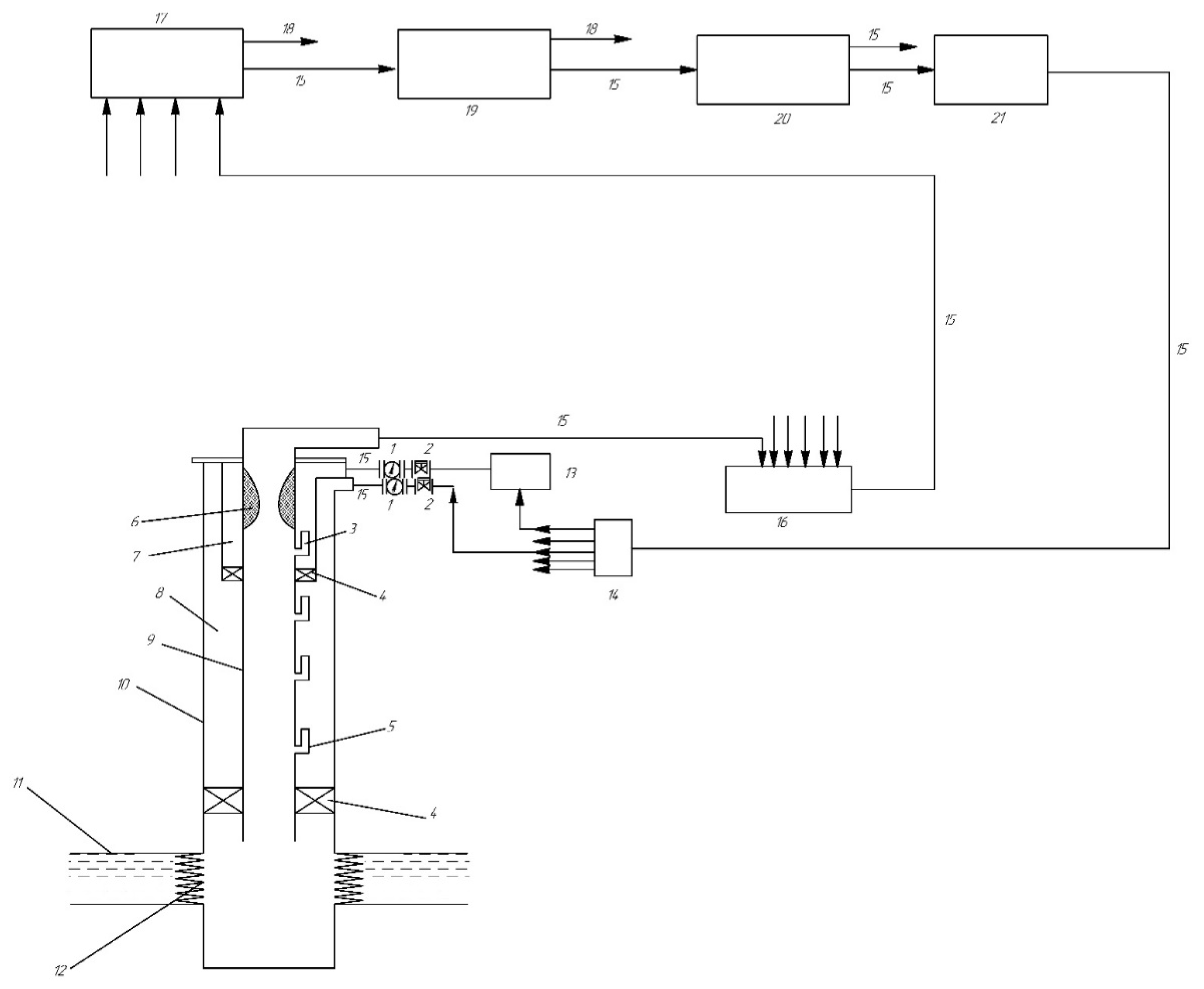
  • An implementation diagram (Figure 7) was developed to prevent the formation of wax deposits in gas-lift oil production wells by periodically injecting hot APG into the annulus.
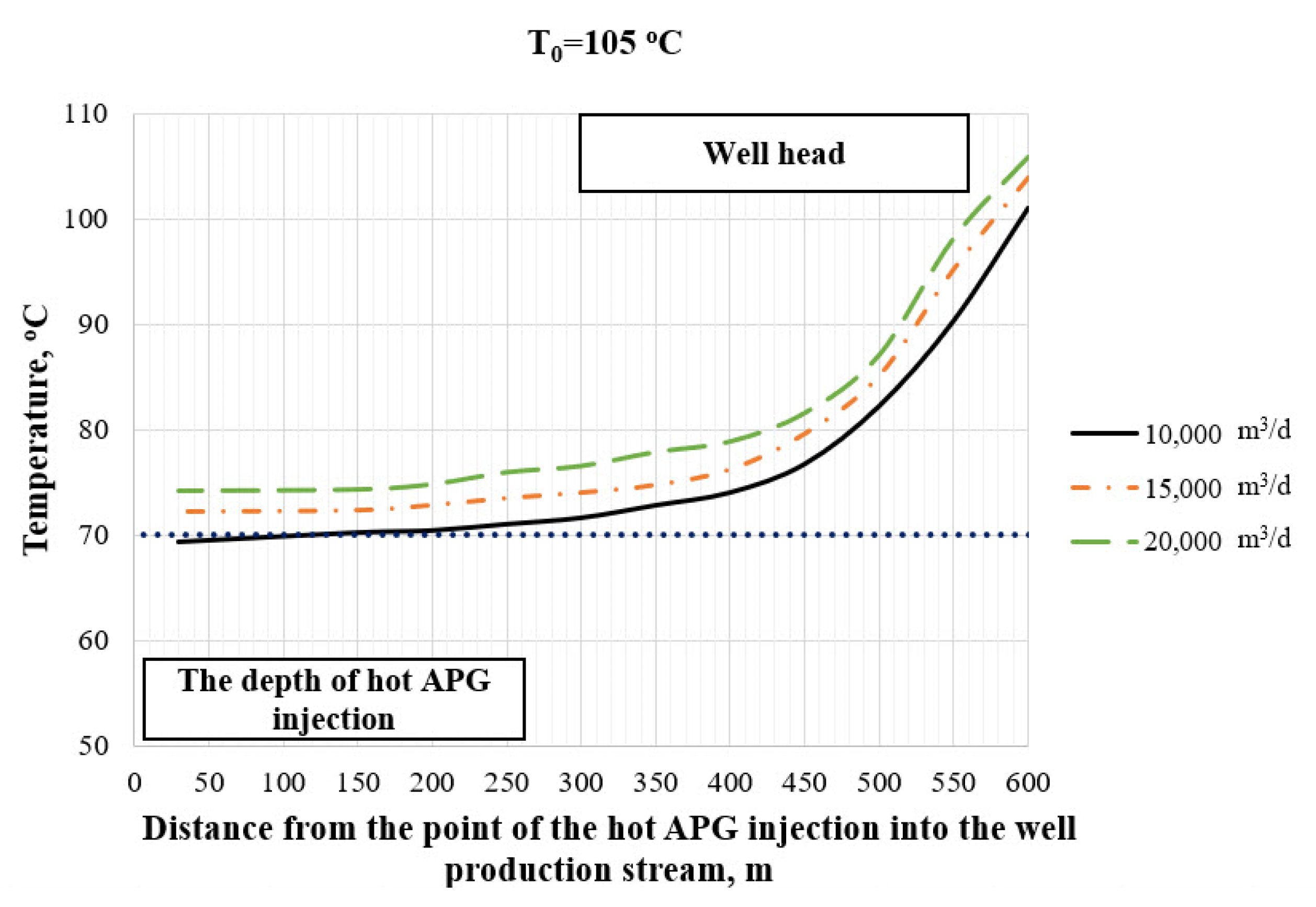
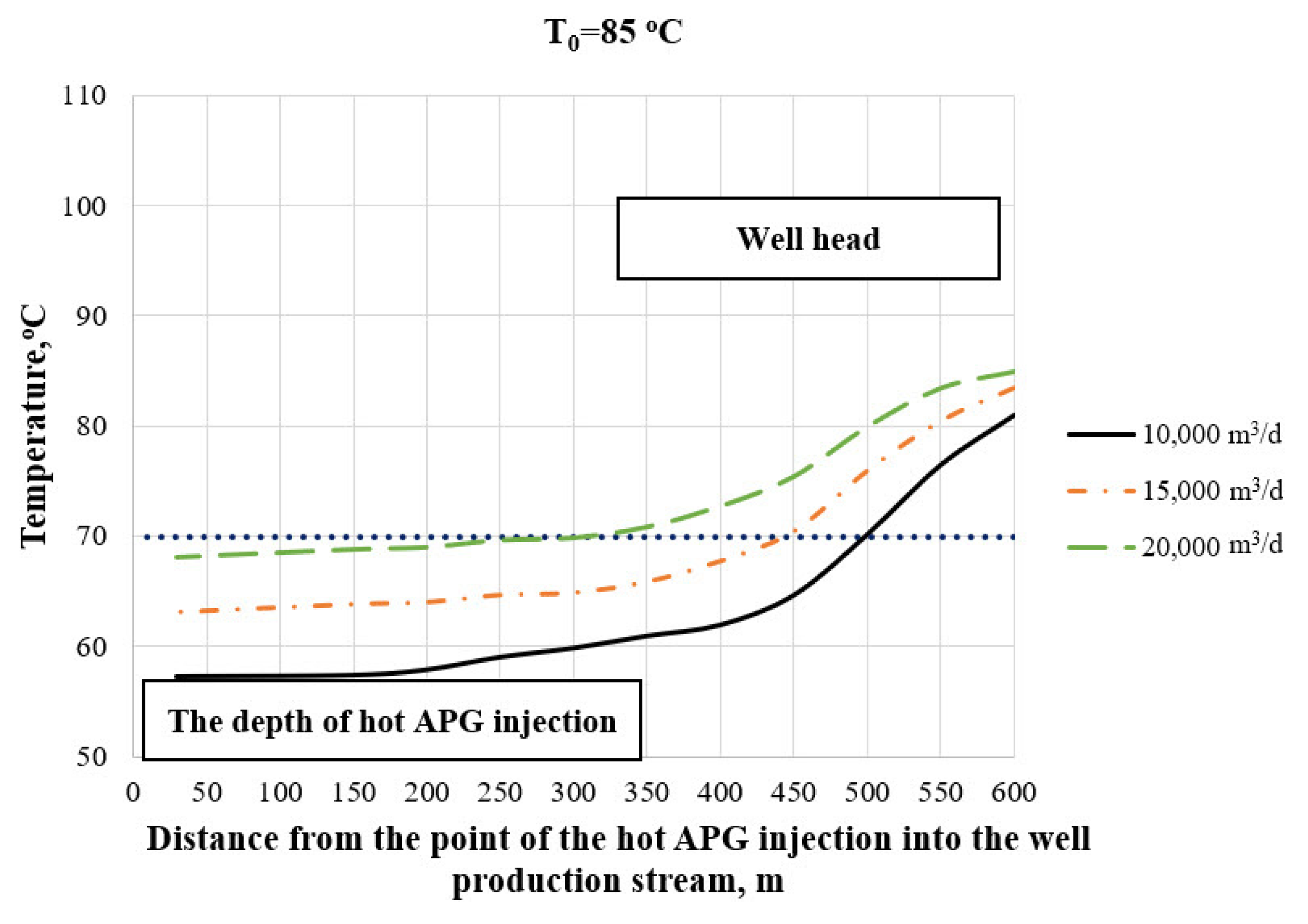
  • For a gas-lift well in the Dragon field (Vietnam), a numerical simulation of the proposed technology was carried out, as a result of which it was found that when organic deposits were formed at a depth of 500 m, the optimal depth of injection of hot APG was 580 m; the depth of lowering the tubing string and the technological string with a heat insulation layer (polyurethane, 25 mm thickness) was 610 m; the inlet temperature of the hot APG injected into the well was 105 °C; optimal flow rate of injected hot APG was 13,000 m3/day; the inter-treatment period of the well operation was 12 days; and the recovery time of the well production rate to the planned value was 8 h.
  • Compared to the conventional method, the proposed technology has proven to be effective in operating conditions of gas-lift wells, where there is intensive wax formation in the tubing string. In addition, the developed technology can be used in the case of injection of a hot hydrocarbon agent or steam instead of associated petroleum gas.
  • A limitation of this study is that we were only able to simulate it, and we have yet to implement it in an actual oil field in Vietnam. Another limitation is that we have yet to determine the associated costs with implementing our proposed method. In the future, we plan to apply the proposed method to practical work in oil and gas fields in Vietnam and broaden the scope of our study by considering additional factors that influence wax formation during gas-lift well production.

Author Contributions

Conceptualization, M.K.R., T.N.V. and A.N.A.; Formal analysis, T.N.V.; Funding acquisition, M.K.R., T.N.V. and A.N.A.; Investigation, M.K.R., T.N.V. and A.N.A.; Methodology, M.K.R., T.N.V. and A.N.A.; Project administration, M.K.R.; Resources, T.N.V. and A.N.A.; Software, T.N.V.; Supervision, M.K.R., T.N.V. and A.N.A.; Validation, M.K.R., T.N.V.; Visualization, M.K.R., T.N.V. and A.N.A.; Writing—Original draft, M.K.R., T.N.V. and A.N.A.; Writing—Review and editing, T.N.V. and A.N.A.; All authors have read and agreed to the published version of the manuscript.

Funding

This research received no external funding.

Institutional Review Board Statement

Not applicable.

Informed Consent Statement

Not applicable.

Data Availability Statement

Not applicable.

Conflicts of Interest

The authors declare no conflict of interest.

References

  1. Bimuratkyzy, K.; Sagindykov, B. The Review of Flow Assurance Solutions with Respect to Wax and Asphaltene. Braz. J. Pet. Gas 2016, 10. [Google Scholar] [CrossRef] [Green Version]
  2. Brown, T.S.; Niesen, V.G.; Erickson, D.D. The Effects of Light Ends and High Pressure on Paraffin Formation. In Proceedings of the SPE Annual Technical Conference and Exhibition, New Orleans, LA, USA, 25 September 1994. [Google Scholar]
  3. Cherepovitsyn, A.E.; Lipina, S.A.; Evseeva, O.O. Innovative approach to the development of mineral raw materials of the Arctic zone of the Russian Federation. J. Min. Inst. 2018, 232, 438–444. [Google Scholar] [CrossRef]
  4. Coutinho, R.; Williams, W.; Waltrich, P.; Mehdizadeh, P.; Scott, S. A Model for Liquid-Assisted Gas-Lift Unloading. In Proceedings of the 18th International Conference on Multiphase Production Technology, Cannes, France, 7 June 2017. [Google Scholar]
  5. Behbahani, T.J.; Beigi, A.A.M.; Taheri, Z.; Ghanbari, B. Investigation of wax precipitation in crude oil: Experimental and modeling. Petroleum 2015, 1, 223–230. [Google Scholar] [CrossRef] [Green Version]
  6. Goodman, N.T.; Joshi, N. A Tale of Two Flowlines-Paraffin Plugging and Remediation. In Proceedings of the SPE Annual Technical Conference and Exhibition, New Orleans, LA, USA, 30 September 2013. [Google Scholar] [CrossRef]
  7. Kopteva, A.V.; Dementyev, A.; Koptev, V. Analysis of the Structure of Viscous Oil Flow for the Development of a System to Prevent the Formation of Paraffin Deposits in Pipelines. In Materials Science Forum; Trans Tech Publications Ltd.: Stafa-Zurich, Switzerland, 2021; Volume 1022, pp. 42–51. [Google Scholar]
  8. Linh, N.K.; Gabov, V.V.; Lykov, Y.V. Substantiation of Parameters of Coal Unloading Process onto Conveyor using Shearer Drums. In IOP Conference Series: Earth and Environmental Science; IOP Publishing: Bristol, UK, 2018; Volume 194, p. 042019. [Google Scholar]
  9. Ilyushin, Y.V.; Novozhilov, I.M. Automation of the Paraffin Oil Production Technological Process. In Proceedings of the 2019 III International Conference on Control in Technical Systems (CTS), St. Petersburg, Russia, 30 October–1 November 2019; pp. 164–167. [Google Scholar] [CrossRef]
  10. Decker, K.; Sutton, R.P. Gas Lift Annulus Pressure. In Proceedings of the SPE Artificial Lift Conference and Exhibition-Americas. Society of Petroleum Engineers, The Woodlands, TX, USA, 28 August 2018. [Google Scholar] [CrossRef]
  11. Drozdov, A.N.; Gorbyleva, Y.A. Improving the Operation of Pump-ejector Systems at Varying Flow Rates of Associated Petroleum Gas. J. Min. Inst. 2019, 238, 415–422. [Google Scholar] [CrossRef] [Green Version]
  12. Du, F.; Nojabaei, B.; Johns, R.T. A Black-Oil Approach to Model Produced Gas Injection for Enhanced Recovery of Conventional and Unconventional Reservoirs. In Proceedings of the SPE Annual Technical Conference and Exhibition, Dallas, TX, USA, 24 September 2018. [Google Scholar] [CrossRef]
  13. Golubev, I.A.; Golubev, A.V.; Laptev, A.B. Practice of using the magnetic treatment devices to intensify the processes of primary oil treating. J. Min. Inst. 2020, 245, 554–560. [Google Scholar] [CrossRef]
  14. Hosseinipour, A.; Sabil, K.M.; Arya Ekaputra, A.; Japper, A.B.; Ismail, L.B. The Impact of the Composition of the Crude Oils on the Wax Crystallization. In Applied Mechanics and Materials; Trans Tech Publications Ltd.: Stafa-Zurich, Switzerland, 2014; Volume 625, pp. 196–200. [Google Scholar]
  15. Kang, P.-S.; Lee, D.-G.; Lim, J.-S. Status of Wax Mitigation Technologies in Offshore Oil Production. In Proceedings of the Twenty-fourth International Ocean and Polar Engineering Conference, Busan, Korea, 15 June 2014. [Google Scholar]
  16. Morenov, V.; Leusheva, E. Influence of the solid phase’s fractional composition on the filtration characteristics of the drilling mud. Int. J. Eng. Trans. B Appl. 2019, 32, 794–798. [Google Scholar] [CrossRef]
  17. Nguyen, V.T.; Rogachev, M.K.; Aleksandrov, A.N. A new approach to improving efficiency of gas-lift wells in the conditions of the formation of organic wax deposits in the Dragon field. J. Petrol. Explor. Prod. Technol. 2020. [Google Scholar] [CrossRef]
  18. Pedersen, K.S.; Fredenslund, A.; Thomassen, P. Properties of Oils and Natural Gases; Gulf Publishing Company: Houston, TX, USA, 1989; Volume 5, p. 385. [Google Scholar]
  19. Aguiar, J.I.S.; Pontifes, A.A.; Nerris, A.; Rogers, J.; Mahmoudkhani, A. Impact of Solvent Treatments for Asphaltenes on Wax Deposition and an Efficient Alternative with Green Surfactants. In Proceedings of the Offshore Technology Conference, Houston, TX, USA, 4 May 2020. [Google Scholar] [CrossRef]
  20. Hassan, A.; Alade, O.; Mahmoud, M.; Al-Majed, A. A Novel Technique for Removing Wax Deposition in the Production System Using Thermochemical Fluids. In Proceedings of the Abu Dhabi International Petroleum Exhibition & Conference, Abu Dhabi, UAE, 11 November 2019. [Google Scholar] [CrossRef]
  21. Fleyfel, F.; Meng, W.; Hernandez, O. Production of Waxy Low Temperature Wells with Hot Gas Lift. In Proceedings of the SPE Annual Technical Conference and Exhibition, Houston, TX, USA, 26 September 2004. [Google Scholar] [CrossRef]
  22. Khaibullina, K.S.; Korobov, G.Y.; Lekomtsev, A.V. Development of an asphalt-resin-paraffin deposits inhibitor and substantiation of the technological parameters of its injection into the bottom-hole formation zone. Periódico Tchê Química 2020, 17, 769–781. [Google Scholar]
  23. Lilya, S.; Dmitry, T.; Rahman, A. Prevention of scale in the downhole equipment and productive reservoir during the oil well operation. J. Appl. Eng. Sci. 2021, 19, 363–368. [Google Scholar] [CrossRef]
  24. Miller, A.; Smith, R.; Dufresne, B.; Mahmoudkhani, A. Out with the Old: Developing a New Test Methodology for Paraffin Wax Dispersion and Inhibition Testing. In Proceedings of the SPE International Conference on Oilfield Chemistry, Galveston, TX, USA, 29 March 2019. [Google Scholar] [CrossRef]
  25. Kar, T.; Firoozabadi, A. Mitigation of Paraffinic Wax Deposition and the Effect of Brine. In Proceedings of the SPE Annual Technical Conference and Exhibition, Calgary, AB, Canada, 23 September 2019. [Google Scholar] [CrossRef]
  26. Raney, K.; Alibek, K.; Shumway, M.; Karathur, K.; Stanislav, T.; West, G.; Jacobs, M. A Novel Biochemical-Based Paraffin Wax Removal Program Providing Revenue Generation and Asset Enhancement. In Proceedings of the SPE International Conference on Oilfield Chemistry, Galveston, TX, USA, 29 March 2019. [Google Scholar] [CrossRef]
  27. Xiu, Z.; Dufils, P.-E.; Zhou, J.; Cadix, A.; Hatchman, K.; Decoster, T.; Ferlin, P. Amphiphilic Wax Inhibitor for Tackling Crude Oil Wax Deposit Challenges. In Proceedings of the SPE International Conference on Oilfield Chemistry, Galveston, TX, USA, 29 March 2019. [Google Scholar] [CrossRef]
  28. Macary, S.; Mahtumov, N.; Muhamadiyev, H.; Akyyev, A.; Mashadov, G.; Al-Hassan, A.; AlWazzan, A. Wax Management: Comprehensive Approach to Assure Flow in Harsh Climate-Brown Field Conditions. In Proceedings of the SPE Russian Petroleum Technology Conference, Moscow, Russia, 15 October 2018. [Google Scholar] [CrossRef]
  29. Stanciu, C.; Fernandez, J.M. Manuscript Title: Paraffin/Asphaltene Cleaning Formulations-Lab Design and Case Studies. In Proceedings of the SPE International Conference and Exhibition on Formation Damage Control, Lafayette, LA, USA, 12 February 2020. [Google Scholar] [CrossRef]
  30. Wilson, A. Novel Polymer Modifications Lead to Next-Generation Pour-Point Depressants. J. Pet. Technol. 2018, 70, 114–116. [Google Scholar] [CrossRef]
  31. Nwankwo, K.O.; Chikwekwem, C.J.; Nwankwo, P.C. Simultaneous Flow Assurance and Production Optimization Using Chemical Paraffin Inhibition Method. In Proceedings of the the SPE Nigeria Annual International Conference and Exhibition, Lagos, Nigeria, 6 August 2018. [Google Scholar] [CrossRef]
  32. Morenov, V.; Leusheva, E. Development of Drilling Mud Solution for Drilling in Hard Rocks (RESEARCH NOTE). Int. J. Eng. 2017, 30, 620–626. [Google Scholar] [CrossRef]
  33. Mydland, S.; Whitson, C.H.; Carlsen, M.L.; Dahouk, M.M.; Yusra, I. Black-Oil and Compositional Reservoir Simulation of Gas-Based EOR in Tight Unconventional. In Proceedings of the SPE/AAPG/SEG Unconventional Resources Technology Conference, Virtual, 20 July 2020. [Google Scholar] [CrossRef]
  34. Feder, J. Gas Lift Operations Require Accurate Predictions of Downhole Annulus Pressure. J. Pet. Technol. 2019, 71, 65–67. [Google Scholar] [CrossRef]
  35. Rogachev, M.K.; Strizhnev, K.V. Bor’ba s oslozhneniyami pri dobyche nefti. [Fighting complications in oil production]. Mosc. Nedra-Bizn. 2006, 1, 296. [Google Scholar]
  36. Santos, H.F.L.; Perondi, E.A.; Wentz, A.V.; Silva Júnior, A.L.; Barone, D.A.C.; Galassi, M.; Ferreira, L.H.T. Annelida, a Robot for Removing Hydrate and Paraffin Plugs in Offshore Flexible Lines: Development and Experimental Trials. SPE Prod. Oper. 2020, 35, 641–653. [Google Scholar] [CrossRef]
  37. Taheri-Shakib, J.; Rajabi-Kochi, M.; Kazemzadeh, E.; Naderi, H.; Shekarifard, A. A comprehensive study of the impact of wax compositions on the wax appearance temperature (WAT) of some Iranian crude oils: An experimental investigation. J. Pet. Sci. Eng. 2018, 165, 67–80. [Google Scholar] [CrossRef]
  38. Khormali, A. Asphaltene precipitation and inhibition in carbonate reservoirs. Pet. Sci. Technol. 2017, 35, 515–521. [Google Scholar] [CrossRef]
  39. Shedid, S.A.; Yakoot, M.S. Simulation study of technical and feasible gas lift performance. Int. J. Pet. Sci. Technol. 2016, 10, 21–44. [Google Scholar]
  40. Thota, S.T.; Onyeanuna, C.C. Mitigation of wax in oil pipelines. Int. J. Eng. Res. Rev. 2016, 4, 39–47. [Google Scholar]
  41. Weingarten, J.S.; Euchner, J.A. Methods for predicting wax precipitation and deposition. SPE Prod. Eng. 1988, 3, 121–126. [Google Scholar] [CrossRef]
  42. White, M.; Pierce, K.; Acharya, T. A review of wax-formation/mitigation technologies in the petroleum industry. SPE Prod. Oper. 2018, 33, 476–485. [Google Scholar] [CrossRef]
  43. Zhao, Y.; Limb, D.; Zhu, X. A Study of Wax Deposition in Pipeline using Thermal Hydraulic Model. In Proceedings of the 18th International Conference on Multiphase Production Technology, Cannes, France, 7 June 2017. [Google Scholar]
  44. Zheng, S.; Saidoun, M.; Palermo, T.; Mateen, K.; Fogler, H.S. Wax deposition modeling with considerations of non-Newtonian characteristics: Application on field-scale pipeline. Energy Fuels 2017, 31, 5011–5023. [Google Scholar] [CrossRef]
  45. Melnikov, V.I. Method and Device for Liquidation and Prevention of Forming of Deposits and Obstructions in Oil and Gas Wells. RU Patent No. 2,248,442, 20 March 2005. [Google Scholar]
  46. Sevic, S.; Grubac, B. Simulation of temperature-pressure profiles and wax deposition in gas-lift wells. Chem. Ind. Chem. Eng. Q. 2017, 23, 537–545. [Google Scholar] [CrossRef] [Green Version]
  47. Aslanov, H.; Novruzov, A.; Harun, A. Managing Wax-Deposition Risks in Oil Subsea Pipelines by Integrating Wax Modeling and Pigging Performance. SPE Prod. Oper. 2019, 34, 625–634. [Google Scholar] [CrossRef]
  48. Beloglazov, I.; Morenov, V.; Leusheva, E.; Gudmestad, O.T. Modeling of Heavy-Oil Flow with Regard to Their Rheological Properties. Energies 2021, 14, 359. [Google Scholar] [CrossRef]
  49. Li, W.; Huang, Q.; Wang, W.; Ren, Y.; Dong, X.; Zhao, Q.; Hou, L. Study on Wax Removal during Pipeline-Pigging Operations. SPE Prod. Oper. 2019, 34, 216–231. [Google Scholar] [CrossRef]
  50. Akopov, E.A.; Akopov, L.E. Method for Cleaning Wells from Paraffin-Resinous Plugs and Device for Its Realization. RU Patent No. 1,810,496, 24 April 1993. [Google Scholar]
  51. Nguyen, V.T. Method of Preventing Formation of Asphaltene, Resinous Paraffin Deposits (ARPD) in Lift Pipes during Gas-Lift Operation of Oil Wells. RU Patent No. 2,740,462, 14 January 2021. [Google Scholar]
  52. Schumberger PIPESIM. Available online: http://www.sis.slb.ru/pipesim/ (accessed on 15 April 2018).
Figure 1. Pipe element during the injection of hot APG into the annular space of the well. 1—Tubing string; 2—Technological pipe (additional pipe); 3—Casing strings; T1— Temperature of the injected APJ in the space between the tubing string 1 and technological pipe 2; T2— Temperature of the fluid inside the tubing string 1; T3—Temperature of the fluid in the space between technological pipe 2 and casing strings 3.
Energies 14 05016 g001
Figure 2. Diagram of the proposed technology.
Energies 14 05016 g002
Figure 3. Determination of the depth of wax formation.
Energies 14 05016 g003
Figure 4. Selection of the optimal thickness of the heat-insulating polyurethane layers.
Energies 14 05016 g004
Figure 5. Algorithm for determining the optimal injection depth and flow rate of hot associated petroleum gas in a gas-lift well.
Energies 14 05016 g005
Figure 6. Determination of the optimal hot APG injection period.
Energies 14 05016 g006
Figure 7. Implementation diagram of the proposed method for combating the wax formation in a gas lift well. 1—flow meter; 2—constant pressure valve; 3—gas-lift valve 3 for pumping heated APG; 4—packer; 5—working gas-lift valve; 6—asphaltene-resin-paraffin deposits (ARPD); 7—technological pipe; 8—annulus; 9—tubing strings; 10—casing string; 11—reservoir; 12—perforation interval; 13—APG heating unit; 14—gas distribution battery; 15—pipeline; 16—production manifold; 17—gas-oil separator; 18—oil enters the collector; 19—gas separator; 20—compressor station; 21—APG purification station from CO2 and H2S.
Energies 14 05016 g007
Figure 8. Annulus hot APG temperature profile, inlet T0 = 105 °C.
Energies 14 05016 g008
Figure 9. Annulus hot APG temperature profile, inlet T0 = 100 °C.
Energies 14 05016 g009
Figure 10. Annulus hot APG temperature profile, inlet T0 = 90 °C.
Energies 14 05016 g010
Figure 11. Annulus hot APG temperature profile, inlet T0 = 85 °C.
Energies 14 05016 g011
Table 1. Optimal composition of the working agent (APG) for a gas-lift well of the Dragon field.
NameOptimal APG Composition
N20.281
CO20.000
CH467.557
C2H68.223
C3H85.849
i-C4H101.632
n-C4H101.959
i-C5H123.244
n-C5H122.311
Pseudo C62.544
Pseudo C72.451
Pseudo C81.934
Pseudo C91.989
Pseudo C100.020
Pseudo C110.007
Publisher’s Note: MDPI stays neutral with regard to jurisdictional claims in published maps and institutional affiliations.

