Article

A New Solar Assisted Heat Pump System with Underground Energy Storage: Modelling and Optimisation

1
Faculty of Mechanical Engineering, Institute of Thermal Power Engineering, Cracow University of Technology, al. Jana Pawła II 37, 31-864 Kraków, Poland
2
Faculty of Electronics and Information Technology, Institute of Control and Computation Engineering, Warsaw University of Technology, ul. Nowowiejska 15/19, 00-665 Warsaw, Poland
3
Czamara Urządzenia Chłodnicze Company, ul. Ceglarska 27, 34-600 Limanowa, Poland
*
Author to whom correspondence should be addressed.
Energies 2021, 14(16), 5137; https://doi.org/10.3390/en14165137
Submission received: 8 July 2021 / Revised: 16 August 2021 / Accepted: 17 August 2021 / Published: 20 August 2021
(This article belongs to the Special Issue Computational Thermal, Energy, and Environmental Engineering)

Abstract

:
The objectives of this work are: (a) to present a new system for building heating which is based on underground energy storage, (b) to develop a mathematical model of the system, and (c) to optimise the energy performance of the system. The system includes Photovoltaic Thermal Hybrid Solar Panels (PVT) panels with cooling, an evacuated solar collector and a water-to-water heat pump. Additionally, storage tanks, placed underground, are used to store the waste heat from PVT panels cooling. The thermal energy produced by the solar collectors is used for both domestic hot water preparation and thermal energy storage. Both PVT panels and solar collectors are assembled with a sun-tracking system to achieve the highest possible solar energy gain. Optimisation of the proposed system is considered to achieve the highest Renewable Energy Sources (RES) share during the heating period. Because the resulting optimisation problem is nonlinear, the classical gradient-based optimisation algorithm gives solutions that are not satisfying. As alternatives, three heuristic global optimisation methods are considered: the Genetic Algorithm (GA), the Particle Swarm Optimisation (PSO) algorithm, and the Jaya algorithm. It is shown that the Jaya algorithm outperforms the GA and PSO methods. The most significant result is that 93% of thermal energy is covered by using the underground energy storage unit consisting of two tanks.

1. Introduction

Building heating takes a significant part of our primary energy consumption and thereby is a crucial player in our transition to a more renewable-based energy future. Most of the renewable energy sources, however, face significant challenges for being intermittent and location-dependent (weather, wind speed, irradiation). Despite these inherent shortcomings, the low operational and maintenance costs as well as their lower greenhouse gas emissions, have made renewable energy sources more popular in the past decades. Recently, EU countries are planning to increase their renewable energy share to 30% as well as to increase energy efficiency by 30% compared to 1990. Since the residential sector represents over 27% of global energy consumption and 17% of CO2 emissions [1], the use of renewable energy systems in building heating is of high importance.
The use of solar-assisted ground source heat pumps is presented by Sun et al. in [2]. To maintain energy efficiency and allow the annual average Coefficient Of Performance (COP) of the heat pump, it is equal to 4.66.
Naranjo-Mendoza et al. [3] have studied an experimental Solar-Assisted Ground Source Heat Pump (SAGSHP) system intended for residential heating. After 19 months of operation, the results show that the system can demonstrate good performance in satisfying the building’s heating needs during the winter period.
A study on the energy efficiency and cost-effectiveness of a SAGSHP system based on PVT panels is shown by Sakellariou et al. in [4] for the city of Thessaloniki (Greece). It was found that the SAGSHP system achieved the highest efficiency with 16 PVT panels, which can cover 73% of the heating load and generate 1.22 times more electricity than it consumes.
Fine et al. [5] have combined a ground source heat pump system with a solar installation to eliminate the effect of the ground thermal imbalance and minimise the system operating costs. A cost-effectiveness analysis of the investment has been then performed to determine the system operating cost.
Nouri et al. [6] presented simulations of different configurations of solar collectors with a ground source heat pump system to meet the heating, cooling, and hot water demand of a house in Tabriz, Iran. The payback period of the studied system is about 13 years.
Verma and Murugesan [7] have studied the performance of a SAGSHP system intended for thermal energy storage during the day and room heating at night. It has been found that an increase in the mass flow rate of the heat transfer medium in the solar collector and in the ground heat exchanger allows a 21% rise in the amount of heat injected into the ground. Ground recharge results in a 23% increase in the system COP for night-time room heating.
Dai et al. [8] have shown that solar heat can be used to accelerate ground regeneration with the heat pump module switched off, but the time of using solar energy to recharge the boreholes should be optimised depending on the water temperature in the solar storage tank.
Verma and Murugesan [9] have proposed a methodology for optimization of the heat transfer area of the solar collector and the length of the ground heat exchanger to achieve a higher COP of a SAGSHP by the Taguchi method. The yearly average COP is equal to 4.23.
In this article, we present a novel heating system for buildings. The system combines the PVT panels with cooling, evacuated solar collector, and water-to-water heat pump. Additionally, storage tanks, placed underground, are used to store the waste heat from PVT panels cooling. The thermal energy produced by the solar collectors is used for both domestic hot water preparation and thermal energy storage. Both PVT panels and solar collectors are assembled with a sun-tracking system to achieve the highest possible solar energy gain. The tank is intentionally not insulated so that it exchanges heat with the ground, heating it in summer so the increased soil temperature heats the tank and, in the worst-case scenario, acts as a natural insulator, with a slow time response, during winter when the tank is discharged. Furthermore, optimisation of the proposed system is considered to achieve the highest renewable energy sources share during the heating period. Because the resulting optimisation problem is nonlinear, the classical gradient-based optimisation algorithm [10,11] gives solutions that are not satisfying. As alternatives three heuristic global optimisation methods are considered: the Genetic Algorithm (GA) [12], the Particle Swarm Optimisation (PSO) algorithm [13] and the Jaya algorithm [14]. Effectiveness of all algorithms is discussed for different sampling periods of the optimisation algorithms (or, in other words, for different frequency of activation of the optimisation routine).
From the performed literature survey, we can observe the lack of studies in the field of optimisation of solar-assisted ground heat pumps with underground energy storage. This work proposes an optimisation procedure for achieving the highest building heating efficiency.

2. A Heating System Based on a Photovoltaic Panel and a Solar Collector

2.1. Process Description

The proposed system (Figure 1) provides a low-temperature heating system (approximately 35 C ) for buildings based on a heat pump, waste heat from PVT panels cooling, and underground thermal energy storage.
The underground heat storage unit comprises high-capacity water tanks being buried in the ground. The use of two water tanks is proposed. The first one is thermally insulated and the second one is not insulated.
The proposed system consists of sun-tracked PVT panels, sun-tracked solar collectors, ground source heat pump, and heat accumulation unit. Two tanks are used to accumulate the heat. The non-insulated tank is used to collect the waste heat from PVT panels. The temperature up to 40 C of water which is a storage medium can be achieved. The excess heat from solar collectors can be stored in the insulated tank. The maximum temperature achieved is 80 C . The non-insulated tank transfers the heat to the ground in the summertime, which allows seasonal storage. It is assumed that the ground is insulated from the sides. Furthermore, the borehole heat exchangers can be charged with the waste heat from PVT panels and heat from solar collectors to allow an efficient ground regeneration. The principal idea of the applied underground energy storage system is to increase the seasonal COP of the heat pump by ground regeneration. Furthermore, the use of underground energy storage units may lead to a reduced number of boreholes, which is economically beneficial. Electrical energy from PVT panels is used to power a heat pump compressor. The excess of electrical energy produced in the March-September period is assumed to be stored in the electrical grid.
Because the heat pump is powered by electrical energy from the PVT panels and also those panels deliver electrical energy for building demands, the electrical and heating demands can be fully covered by the proposed solution.
The PVT panels specification is described in the first author’s previous work [15] while Solar collectors data and drawing are provided in [16]. Heat pump thermal power output is 50 kW.

2.2. Comparison with Other Systems

The proposed solution can be competitive with gas and biomass boiler-based heating systems since the solution is entirely based on renewable energy sources (solar energy), and the maintenance costs of the system are low. Compared to a typical ground-source heat pump system, the proposed heating system reduces the length of boreholes and efficient ground regeneration. Therefore, higher values of seasonal COP can be achieved. The proposed system can be an alternative to District Heating Systems since it can be applied in the places where District Heating Networks cannot be installed (for example, in the suburb area).

2.3. Process Modelling

We present a numerical model to test the merits of our proposed design. Hence, the results are limited to a case study only. In what follows the governing equations and the appropriate boundary conditions are presented and discussed. The major component of the heating system are storage tanks that contain water. The tanks temperatures T 1 and T 2 are determined from the following differential equations
ρ w c w π D 2 4 L d T 1 d τ = Q sol , PVT φ Q HP + Q ground , 1
ρ w c w π D 2 4 L d T 2 d τ = Q sol , SC ( 1 φ ) Q HP + Q ground , 2
where:
  • D is the tank diameter (3 m);
  • L is length of the tank (10 m);
  • Q ground , 1 and Q ground , 2 are ground heat transfer to the first and the second tank, respectively;
  • Q HP is heat transferred through the heat pump to the building;
  • Q sol , PVT is solar heat flow from PVT panels cooling;
  • Q sol , SC is solar heat flow from solar collectors;
  • T 1 , T 2 are water temperatures in the storages tanks 1 and 2, respectively;
  • c w = 4180 J / ( kg K ) is specific heat of water;
  • φ is the ratio of heat taken from the tank 1 to the entire heat taken by the heat pump;
  • ρ w = 1000 kg / m 3 is density of water.
Solar heat flows Q sol , PVT and Q sol , SC are calculated as
Q sol , PVT = q A PVT η PVTt
Q sol , SC = q A SC η SC
where A PVT = 259.2 m 2 (the electrical power output is 47 kW) and A SC = 54.4 m 2 (the thermal power output 35 kW) are the surface area of PVT panels and solar collectors, respectively, η PVTt and η SC are the PVT panels and solar collector solar-thermal energy conversion efficiency, q is monthly averaged solar daily irradiation (Table 1). The data is collected for Limanowa in the south of Poland.
Heat transferred through the heat pump to the building is calculated as
Q HP = Q b 1 1 COP
where COP is the coefficient of performance and Q b is a building heating demand calculated as
Q b = U A b ( T set T ext )
Thermal transmittance of the building is denoted as U A b (W/K). T ext is the external temperature varied daily, and T set is a set temperature given as 20 C . That temperature is set only for heating season.
COP of the heat pump is calculated as
COP = η cycle T L T L T S
where the temperature at the hot side of heat pump T L = 40 C , and the temperature at the cold side of heat pump T S is either 20 C when the T 1 or T 2 is higher than 20 C or is equal to T 1 or T 2 otherwise. Heat pump cycle efficiency η cycle is assumed to be equal 0.4. The thermal efficiency of the PVT panel is η PVt = 0.65 , the thermal efficiency of the solar collector is η SC = 0.8 . The return temperature to the buffer tank is 35 C . We assume that the heat taken from the underground storage unit is equal to current energy demand of the building. We do not model the heat exchanges. The considered case study is an idealised one, but its goal is to optimise the operation of the underground energy storage unit in order to limit the use of borehole heat exchanger. It is considered that the Domestic Hot Water (DHW) demand is equal to 30% of the total heating demand.
Ground heat transfer to the first and second tank is calculated as
Q ground , 1 = h 1 π D L ( T g , 1 T 1 )
Q ground , 2 = h 2 π D L ( T g , 2 T 2 )
where T g , 1 and T g , 2 are the area averaged ground temperatures along tank circumference calculated from ground heat transfer model of the ground surrounding tank 1 and tank 2, respectively. We have
ρ c T g τ = k 2 T g x 2 + k 2 T g y 2
with boundary conditions
T g x ( W , y ) = 0
T g y ( x , 0 ) = 0
k T g x ( x , H t ) = U g , top ( T ext T g , av )
For the tank 1, we have
k T g r D 2 , φ = h 1 ( T g T 1 )
For the tank 2, we have
k T g r D 2 , φ = h 2 ( T g T 2 )
where
  • H t is the total height of the domain assumed as 13 m;
  • T g , av is the yearly average ground temperature, assumed to be equal to 7.5 C ;
  • T g is the ground temperature, the initial ground temperature is assumed to be equal to 20 C ;
  • U g , top is the overall heat transfer coefficient from the ground top layer to the external environment, equal to 0.7 W / ( m 2 K ) ;
  • W is the width of the domain, assumed as 10 m;
  • c is specific heat capacity of the ground;
  • h 1 = 250 W / ( m 2 K ) and h 2 = 0.05 W / ( m 2 K ) are the heat transfer coefficients from the tank 1 and tank 2, respectively;
  • k is thermal conductivity of the ground;
  • x and y are Cartesian coordinates;
  • ρ is density of the ground.
It is very difficult to predict the thermal and electrical efficiency of PVT. The electrical efficiency is assumed to be equal to 18% and thermal efficiency to 60%. In the case of PVT, some parts of solar energy is converted to: electricity 18%, heat 65%, and losses 17%.
The heat conduction within the ground domain is considered to be two-dimensional and transient. The transient heat conduction equation is discretised using an implicit control volume method. An in-house MATLAB code is developed to calculate the temperature distribution in the ground leading to ground heat transfer rate Q ground , which is then substituted into Equations (1) and (2) for calculating the tank water temperature. The solar collectors and PVT panel heat gains are subsequently determined as well as the building heat demand.

2.4. Optimisation Objective

Optimisation is performed to achieve the highest contribution of the underground energy storage unit to cover as much as possible the heating demands of the building. The system is fully based on renewable energy because the electricity from PVT is delivered to the heat pump. We optimise the system to achieve the following goals:
  • To use less electrical energy due to the increase in the overall COP of the heat pump;
  • To use mostly the underground energy storage unit instead of a borehole heat exchanger to allow efficient ground regeneration.
The decision variable φ is the ratio of heat taken from the tank 1 to the entire heat taken by the heat pump. Its changes in time should be optimised during the heating period, to achieve the highest renewable energy gain from the system. The actual number of optimised variables depends on the sampling time T s . For example, for the sampling times 24 h, 12 h, 6 h, 3 h, 2 h, and 1 h, the total numbers of calculated variables are 365, 730, 1460, 2920, 4380, and 8760, respectively. The objective function is defined as follows
Max rat = i = 1 n Q b ( τ ) 1 1 COP ( τ , φ ) i = 1 n Q b ( τ )
We maximise the heat transferred from the heat pump to the building over the entire heating season, where n is the number of time steps during the heating season. The rat defined as a ratio of heat delivered by heat pump utilizing energy storage to heating demand of the building. The COP is time-dependent and is calculated based on the source fluid temperature which is equal to either T 1 or T 2 (calculated from Equations (1) and (2). The temperatures T 1 and T 2 depend on the decision variable φ . Optimisation is carried out subject to the following constraint imposed on the decision variable
0 φ 1

3. Optimisation Methods Used

3.1. Gradient-Based Optimisation Algorithm

In this work, the Sequential Quadratic Programming (SQP) algorithm originally presented in [11] is used. The SQP algorithm finds the solution of a nonlinear constrained optimisation problem by solving a series of quadratic programming tasks that approximate the rudimentary nonlinear one. The SQP algorithm is very efficient in nonlinear optimisation with numerous decision variables and constraints [10]. Due to its efficiency, it is frequently used in different engineering tasks, e.g., in constrained identification of dynamical models [17], to find optimal control policy in Model Predictive Control (MPC) algorithms [18] or to optimise the operation of technological processes [19]. Unfortunately, as the SQP algorithm relies on the gradient vector of the minimised cost-function, it may give local minima only.

3.2. Genetic Algorithm

The Genetic Algorithm (GA) is an optimisation method inspired by the process of natural selection observed in living creatures [12]. Initially, a number of random vectors (“individuals”) are generated. In the consecutive generations (epochs) new individuals are formed as a result of the following biologically inspired operators: mutation, crossover and selection. After many repetitions, the individuals adapt to the environment defined by the solved optimisation problem. The genetic algorithm is a derivative-free optimisation method. Thanks to simplicity of implementation, it is very frequently used to solve numerous scientific and engineering tasks, such as: optimisation of gains of state observers [20], optimisation of controllers’ parameters [21], optimisation of control policy in MPC [22], optimisation of settings for a fuel engine [23], optimisation of hybrid energy systems [24], integrated process planning, and scheduling [25].

3.3. Particle Swarm Optimisation Algorithm

The Particle Swarm Optimisation (PSO) algorithm is a gradient-free evolutionary algorithm which is used to solve numerous complex optimisation problems [13]. The change of position (originally named “velocity”) for each particle in the consecutive generations is obtained as a weighted sum of “velocity” from the previous generation taking into account some differences between the current position relative to the best-known position of the particle and the best-known position achieved by the whole swarm. Currently, the PSO algorithm is very popular; it is applied more frequently than the classical GA method. It is reported to solve multiple problems, e.g., parameter identification [26], optimal siting and sizing methodology to design an energy storage system [27], gas turbine modelling for fault detection [28], optimisation of control policy in MPC [22], optimisation of hybrid energy systems [24], optimisation of power dispatch problems [29].

3.4. Jaya Algorithm

Jaya is a relatively new heuristic optimisation algorithm [14]. In this approach, single particles in each generation should be moved toward the best solution and evade from the worst. A characteristic feature of Jaya, unlike previously considered GA and PSO algorithms (as well as many other heuristic optimisation algorithms), is the fact that it does not require any parameters, which is a huge advantage. The Jaya algorithm has been reported to be very successful in many difficult engineering problems. Example applications are: a proton exchange membrane fuel cell stack design optimisation [30], parameter identification [26], optimisation of a micro-channel heat sink [31], optimisation of thermoelectric coolers, heat pumps and heat exchangers [32].

4. Results of Simulations

In this section, the results obtained by means of the classical gradient-based SQP optimisation algorithm as well as three heuristic ones (the PSO, GA, and Jaya approaches) are discussed. All optimisation algorithms have been implemented in MATLAB.
At first, the maximal number of iterations of the compared optimisation algorithms must be determined experimentally. The following values of the sampling time T s of the optimisation algorithm are taken into account: 24 h, 12 h, 6 h, 3 h, 2 h, and 1 h. The maximal number of iterations is determined by trial and error; the results are given in Table 2. In general, the number of necessary iterations grows as the sampling time is decreased. The gradient-based SQP algorithm needs much fewer iterations than the heuristic ones. Furthermore, it turns out that for all heuristic optimisation methods considered, the number of necessary iterations is the same for the consecutive sampling time values 24 h, 12 h, 6 h, 3 h, and 2 h. The only exception is observed for the sampling time 1 h. In such a case, both PSO and genetic algorithms need as many as 3000 iterations whereas for the Jaya method, 2500 are sufficient. It must be noted that in many cases, the optimisation algorithms need a much lower number of iterations; the values given in Table 2 are maximal ones. Typically, when the optimised cost-function does not change noticeably in many consecutive iterations, the optimisation procedure is stopped.
Next, the number of individuals must be determined in all three heuristic optimisation approaches. Although there are some differences in the way the number of individuals influences the convergence rate of the considered PSO, GA, and Jaya algorithms, they are not very significant. Having carried out a series of experiments, it has been found out that 30 individuals is sufficient. For a lower number of individuals, convergence is slow whereas for a higher number, there is no improvement of the convergence rate. When there are too many individuals, e.g., more than 50 or even 100, convergence is even slower than for the chosen value 30 and the algorithm needs a great number of iterations to obtain comparable results as those for 30 individuals. Even in the case of short sampling time T s , increasing the number of individuals does not work.
Now let us analyse the best results obtained by the compared optimisation algorithms that are detailed in Table 3 (the worst and the best results for the consecutive sampling time T s values are denoted by colours). Because the final solution obtained depends on the random initial point, each tested configuration has been calculated 10 times, starting from different random initial points and the best results are only presented. Let us summarise the obtained results:
  • In spite of the fact that in the gradient-based SQP algorithm relatively high number of iterations is used, it gives the worst results. Probably, the obtained results are shallow local minima.
  • All three tested heuristic optimisation methods give better results than the SQP one.
  • The PSO algorithm is the worst one in the group of the heuristic optimisation methods. Numerous attempts have been made to improve the results by using a larger population of individuals or by increasing the number of possible iterations, but such approaches do not lead to any better results. Typically, after some 50–80% of the allowed iterations, the optimised cost-function is practically constant and calculations are terminated.
  • In comparison with the PSO algorithm, better results, in particular for the sampling time T s equal to 24 h, 12 h, or 6 h, are obtained by the genetic algorithm, although we may observe that as the sampling time is reduced, the genetic algorithm gives worse results. For the sampling time equal to 3 h, 2 h, or 1 h, the obtained results are only slightly better than those obtained by the PSO algorithm. Similarly to the PSO algorithm, also in the case of the genetic algorithm, increasing the number of individuals or the number of possible iterations does not yield better results.
  • Generally, the Jaya algorithm gives the best results, the only exception is for T s = 24 h in which the genetic algorithm is better, but the difference is really insignificant.
  • It is important that the Jaya algorithm finds good solutions for all tested values of the sampling time T s , which is not true in the case of the second-best approach, i.e., the genetic algorithm.
  • As far as heuristic optimisation algorithms are concerned, the presented results have been achieved for exactly the same number of maximal iterations (as specified in Table 2 for the consecutive values of the sampling time T s , the only exception is for the sampling time 1 h, the Jaya algorithm needs a lower number of iterations) and population size (30 individuals).
  • Decreasing the sampling instant T s leads to increasing the number of decision variables in the optimization problem. The more the decision variables, the more difficult the optimization task. Hence, more iterations of the optimization algorithms are necessary as shown in Table 2. It greatly increases the resulting calculation time.
  • Since decreasing the sampling time T s does not improve the final value of the cost-function but only makes calculations more time-consuming, it is recommended to use quite long sampling periods, e.g., 24 h or 12 h.
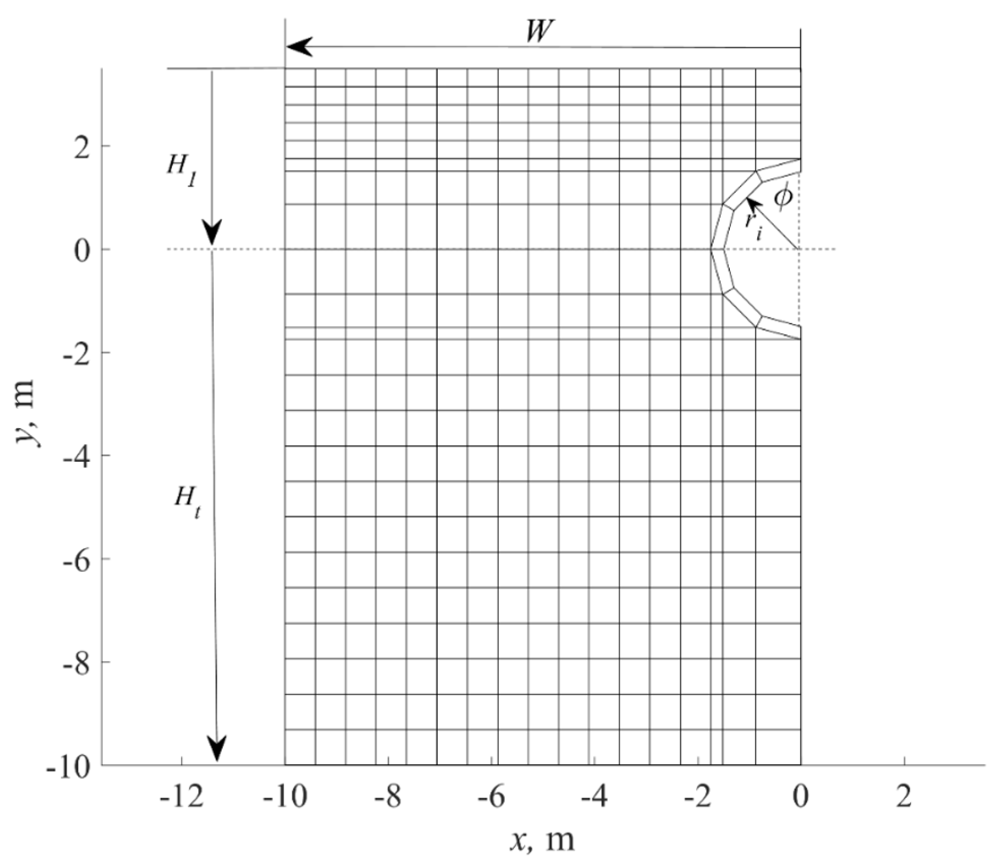
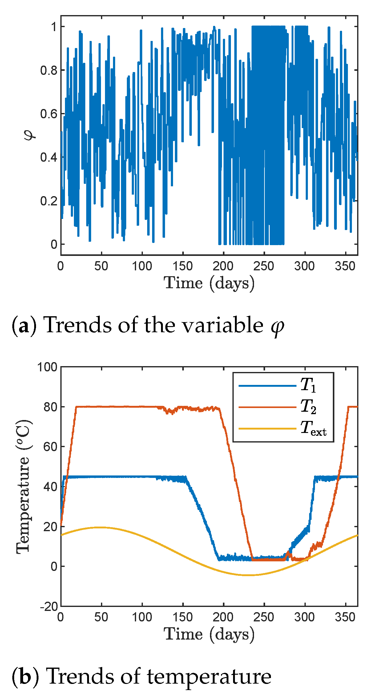
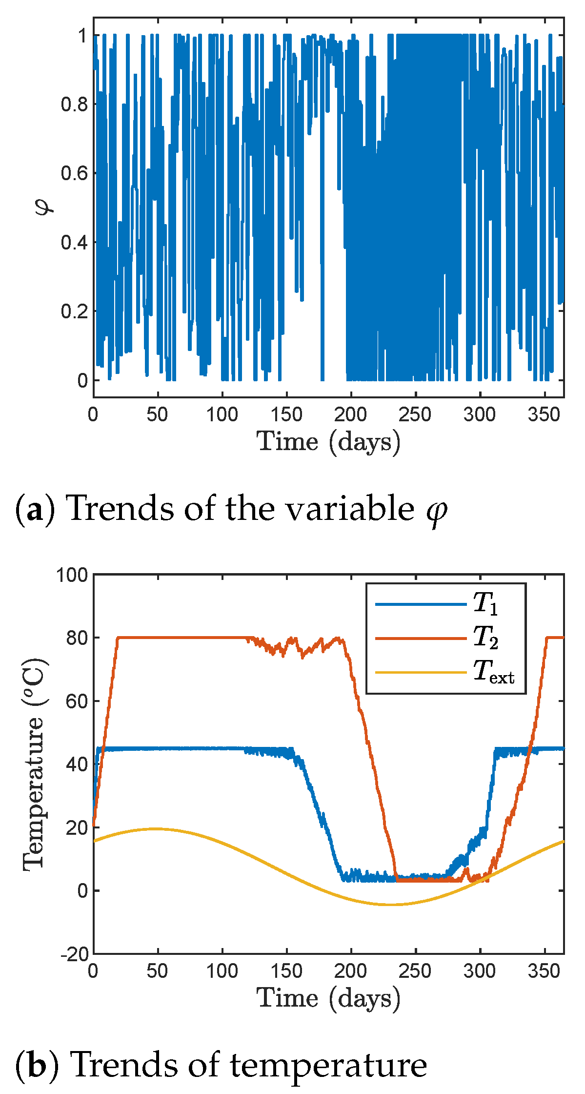
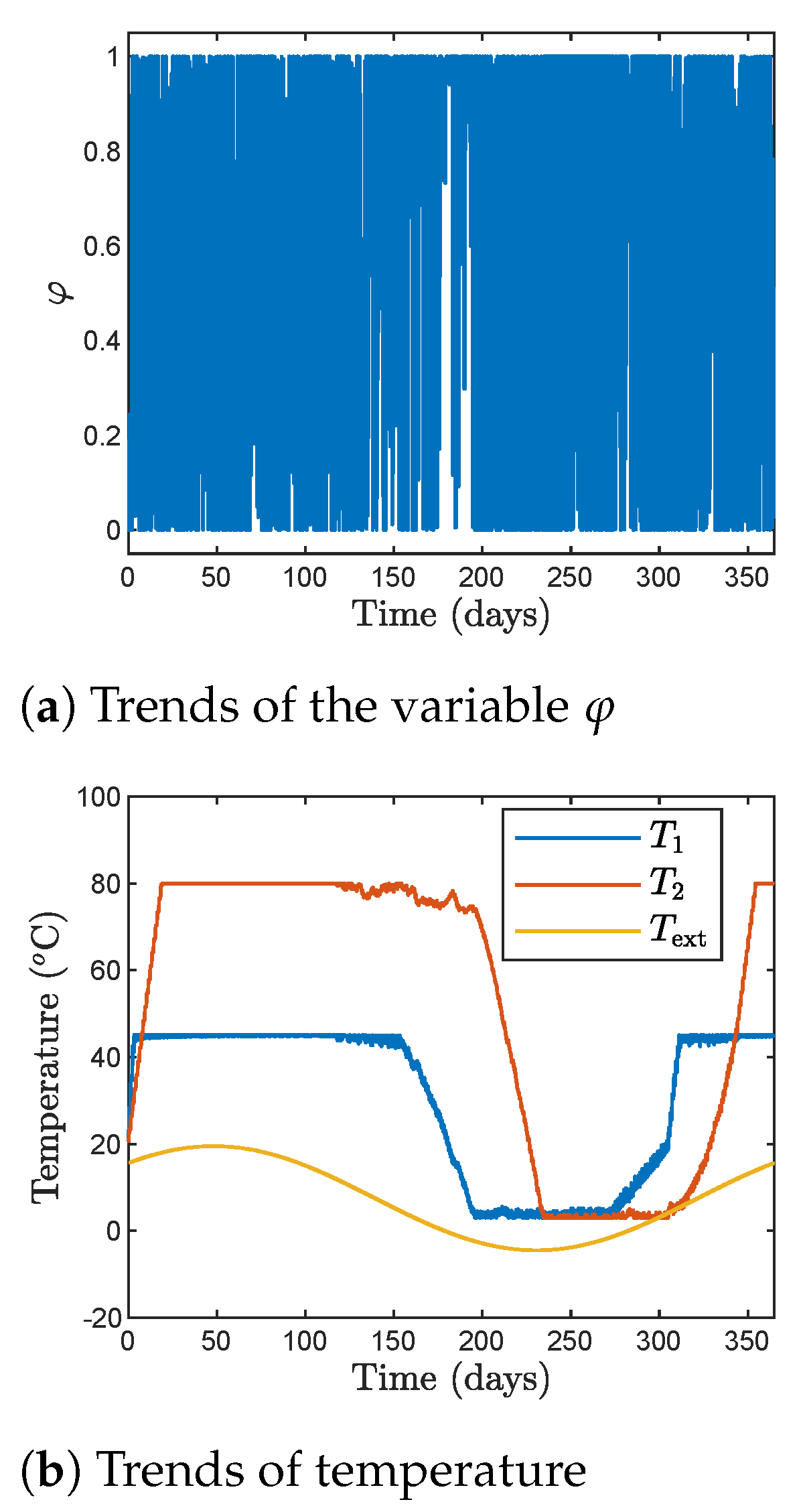
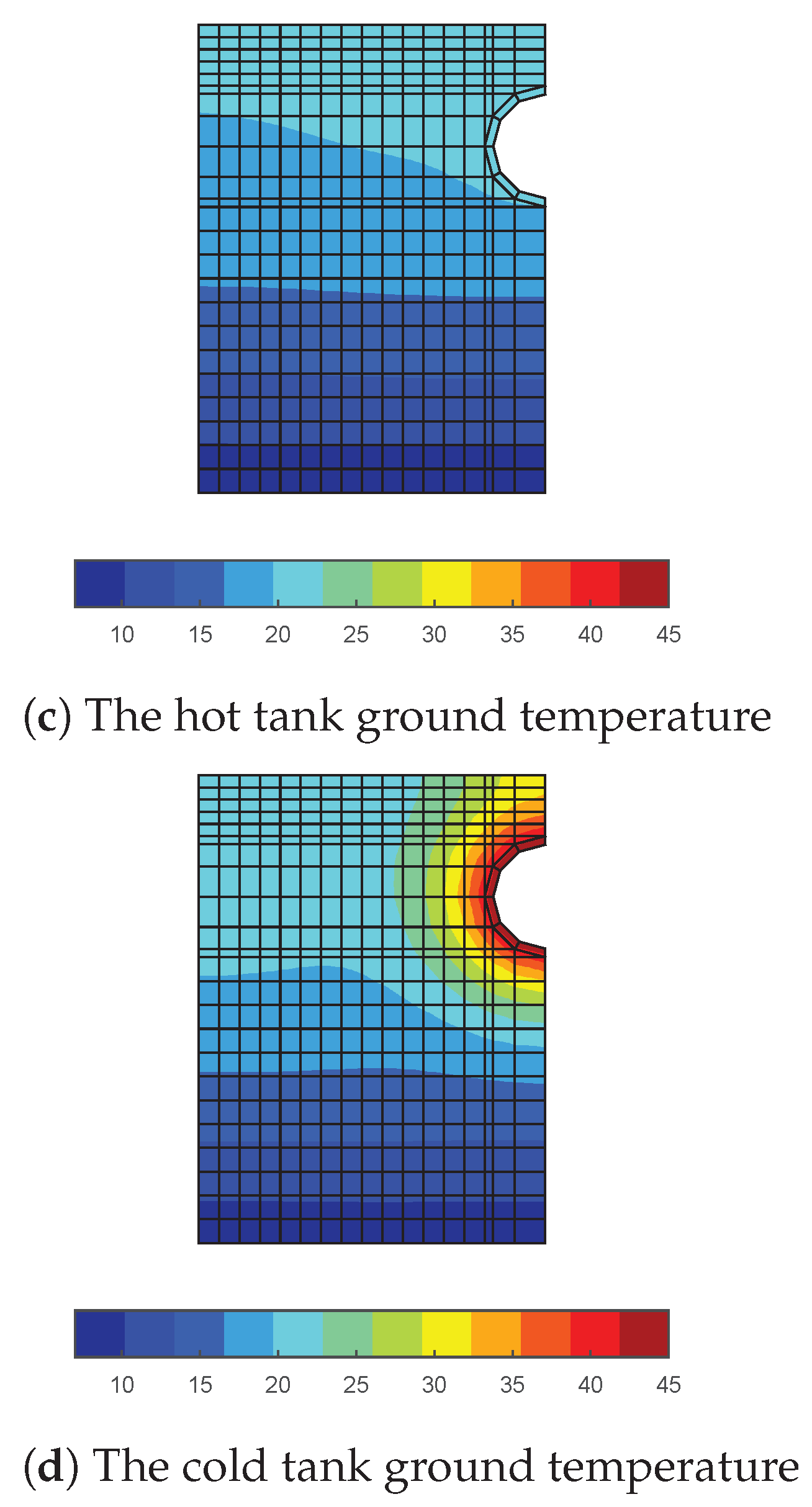
Figure 2 shows the numerical mesh (a ground domain which dimensions) used in the calculations. Temperatures of both tanks in the following figures are shown using that mesh. Figure 3 depicts the results obtained by the genetic algorithm when the sampling time is T s = 24 h. The following subplots show: the trends of the variable φ (the left-top subplot), the trends of temperatures T 1 , T 2 and T ext (the right-top subplot), the hot tank ground temperature (the left-bottom subplot) as well as the cold tank ground temperature (the right-bottom subplot). The trends show changes during the entire year. Figure 4 shows the results obtained by the Jaya algorithm, also for T s = 24 h. As Table 3 suggests, both algorithms give very similar values of the cost-function. Hence, the obtained temperatures in hot and cold tanks are very similar. Figure 5 shows the results obtained by the Jaya algorithm when the sampling time T s is decreased to 6 h. We may notice many frequent changes of the variable φ , which is a result of decreasing the sampling time. On the other hand, the temperature profiles are quite similar to those shown in Figure 4, obtained for T s = 24 h. Hence, as observed from the results presented in Table 3, it is recommended to use quite long sampling periods, e.g., 24 h or 12 h. The thermal demand for the best result (the Jaya algorithm) is 3.43 × 10 11 J.

5. Conclusions

This works describes a novel heating system for buildings that includes the photovoltaic panels with cooling, evacuated solar collector, water-to-water heat pump and underground storage tanks. Optimisation of the described system is considered to achieve the highest renewable energy sources share during the heating period. Because the resulting optimisation problem is nonlinear, the classical gradient-based optimisation SQP algorithm gives solutions that are not satisfying. Hence, as alternatives, three heuristic global optimisation methods are considered: GA, PSO, and Jaya algorithms. It is demonstrated that the Jaya algorithm is the best one for the most of considered scenarios. The GA approach gives quite good results, but only in some cases. The PSO algorithm is the worst one among the heuristic optimisation methods, only slightly better than the classical SQP method. A total of 93% of thermal energy is covered by using the underground energy storage unit consisting of two tanks.
The described system has been installed in Limanowa, Poland, in the headquarters of the Czamara Urządzenia Chłodnicze company (https://www.czamara.net.pl/ (accessed on 19 August 2021)). The proposed system can be a very good alternative for a district heating network in places where it is impossible or not economically viable to install the classical solution. In practice, it delivers about 85% of heating energy from the underground energy storage.

Author Contributions

Conceptualisation, M.Ł., P.O. and M.C.; methodology, M.Ł., P.O. and M.C.; software, M.Ł. and P.O.; validation, M.Ł., P.O. and M.C.; analysis, M.Ł. and P.O.; investigation, M.Ł. and P.O.; resources, M.Ł., P.O. and M.C.; data curation, M.Ł. and P.O.; writing–original draft preparation, M.Ł. and P.O.; writing–review and editing, M.Ł. and P.O.; visualisation, M.Ł.; project administration, M.Ł., P.O. and M.C.; funding acquisition, M.Ł., P.O. and M.C. All authors have read and agreed to the published version of the manuscript.

Funding

This research was funded by National Research and Development Funds in the framework of the SOPSAR project.

Institutional Review Board Statement

Not applicable.

Informed Consent Statement

Not applicable.

Data Availability Statement

Not applicable.

Conflicts of Interest

The authors declare no conflict of interest. The funders had no role in the design of the study; in the collection, analyses, or interpretation of data; in the writing of the manuscript, or in the decision to publish the results.

Acronyms

COPCoefficient Of Performance
DHWDomestic Hot Water
GAGenetic Algorithm
MPCModel Predictive Control
PSOParticle Swarm Optimisation
PVTPhotovoltaic Thermal Hybrid Solar Panels
RESRenewable Energy Sources
SAGSHPSolar-Assisted Ground Source Heat Pump
SQPSequential Quadratic Programming

References

  1. Vallati, A.; Ocłoń, P.; Colucci, C.; Mauri, L.; de Lieto Vollaro, R.; Taler, J. Energy analysis of a thermal system composed by a heat pump coupled with a PVT solar collector. Energy 2019, 174, 91–96. [Google Scholar] [CrossRef]
  2. Sun, T.; Yang, L.; Jin, L.; Luo, Z.; Zhang, Y.; Liu, Y.; Wang, Z. A novel solar-assisted ground-source heat pump (SAGSHP) with seasonal heat-storage and heat cascade utilization: Field test and performance analysis. Sol. Energy 2020, 201, 362–372. [Google Scholar] [CrossRef]
  3. Naranjo-Mendoza, C.; Oyinlola, M.A.; Wright, A.J.; Greenough, R.M. Experimental study of a domestic solar-assisted ground source heat pump with seasonal underground thermal energy storage through shallow boreholes. Appl. Therm. Eng. 2019, 162, 114218. [Google Scholar] [CrossRef]
  4. Sakellariou, E.I.; Axaopoulos, P.J.; Wright, A.J. Energy and economic evaluation of a solar assisted ground source heat pump system for a north Mediterranean city. Energy Build. 2021, 231, 110640. [Google Scholar] [CrossRef]
  5. Fine, J.P.; Nguyen, H.V.; Friedman, J.; Leong, W.H.; Dworkin, S.B. A simplified ground thermal response model for analyzing solar-assisted ground source heat pump systems. Energy Convers. Manag. 2018, 165, 276–290. [Google Scholar] [CrossRef]
  6. Nouri, G.; Noorollahi, Y.; Yousefi, H. Designing and optimization of solar assisted ground source heat pump system to supply heating, cooling and hot water demands. Geothermics 2019, 82, 212–231. [Google Scholar] [CrossRef]
  7. Verma, V.; Murugesan, K. Experimental study of solar energy storage and space heating using solar assisted ground source heat pump system for Indian climatic conditions. Energy Build. 2017, 139, 569–577. [Google Scholar] [CrossRef]
  8. Dai, L.; Li, S.; Mu, L.D.; Li, X.; Shang, Y.; Dong, M. Experimental performance analysis of a solar assisted ground source heat pump system under different heating operation modes. Appl. Therm. Eng. 2015, 75, 325–333. [Google Scholar] [CrossRef]
  9. Verma, V.; Murugesan, K. Optimization of solar assisted ground source heat pump system for space heating application by Taguchi method and utility concept. Energy Build. 2014, 82, 296–309. [Google Scholar] [CrossRef]
  10. Nocedal, J.; Wright, S. Numerical Optimization; Springer: Berlin, Germany; New York, NY, USA, 2006. [Google Scholar]
  11. Powell, M.J.D. A fast algorithm for nonlinearly constrained optimization calculations. In Numerical Analysis; Lecture Notes in Mathematics; Watson, G.A., Ed.; Springer: Dundee, UK, 1978; Volume 630, pp. 144–157. [Google Scholar]
  12. Goldberg, D.E. Genetic Algorithms in Search, Optimization, and Machine Learning; Addison-Wesley: Reading, MA, USA, 1989. [Google Scholar]
  13. Kennedy, J.; Eberhart, R. Particle swarm optimization. In Proceedings of the IEEE International Conference on Neural Networks, Perth, WA, Australia, 27 November–1 December 1995; pp. 1942–1948. [Google Scholar]
  14. Rao, R.V. A simple and new optimization algorithm for solving constrained and unconstrained optimization problems. Int. J. Ind. Eng. Comput. 2016, 7, 19–34. [Google Scholar]
  15. Ocłoń, P.; Cisek, P.; Kozak-Jagieła, E.; Taler, J.; Taler, D.; Skrzyniowska, D.; Fedorczak-Cisak, M. Modeling and experimental validation and thermal performance assessment of a sun-tracked and cooled PVT system under low solar irradiation. Energy Convers. Manag. 2020, 222, 113289. [Google Scholar] [CrossRef]
  16. Zima, W.; Cisek, P.; Cebula, P. Mathematical model of an innovative double U-tube sun-tracked PTC and its experimental verification. Energy 2021, 235, 121293. [Google Scholar] [CrossRef]
  17. Ławryńczuk. Identification of Wiener models for dynamic and steady-state performance with application to solid oxide fuel cell. Asian J. Control. 2019, 21, 1836–1846. [Google Scholar] [CrossRef]
  18. Ławryńczuk, M. Computationally Efficient Model Predictive Control Algorithms: A Neural Network Approach. In Studies in Systems, Decision and Control; Springer: Cham, Switzerland, 2014; Volume 3. [Google Scholar]
  19. Aji, S.S.; Kim, Y.S.; Ahn, K.Y.; Lee, Y.D. Life-cycle cost minimization of gas turbine power cycles for distributed power generation using sequential quadratic programming method. Energies 2018, 11, 3511. [Google Scholar] [CrossRef] [Green Version]
  20. Białoń, T.; Pasko, M.; Niestrój, R. Developing induction motor state observers with increased robustness. Energies 2020, 13, 5487. [Google Scholar] [CrossRef]
  21. Chen, J.; Zhang, C.; Li, K.; Zhan, Y.; Sun, B. Hybrid adaptive control for PEMFC gas pressure. Energies 2020, 13, 5334. [Google Scholar] [CrossRef]
  22. Narayanan, M.; de Lima, A.F.; de Azevedo Dantas, A.F.O.; Commerell, W. Development of a coupled TRNSYS-MATLAB simulation framework for model predictive control of integrated electrical and thermal residential renewable energy system. Energies 2020, 13, 5761. [Google Scholar] [CrossRef]
  23. Stoumpos, S. Multiobjective optimisation of a marine dual fuel engine equipped with exhaust gas recirculation and air bypass systems. Energies 2020, 13, 5021. [Google Scholar] [CrossRef]
  24. Torres-Madroñero, J.L.; Nieto-Londoño, C.; Sierra-Pérez, J. Hybrid energy systems sizing for the colombian context: A genetic algorithm and particle swarm optimization approach. Energies 2020, 13, 5648. [Google Scholar] [CrossRef]
  25. Zhang, X.; Zhang, H.; Yao, J. Multi-objective optimization of integrated process planning and scheduling considering energy savings. Energies 2020, 13, 6181. [Google Scholar] [CrossRef]
  26. Ding, T.; Chang, L.; Li, C.; Feng, C.; Zhang, N. A mixed-strategy-based whale optimization algorithm for parameter identification of hydraulic turbine governing systems with a delayed water hammer effect. Energies 2018, 11, 2367. [Google Scholar] [CrossRef] [Green Version]
  27. Lamedica, R.; Ruvio, A.; Palagi, L.; Mortelliti, N. Optimal siting and sizing of wayside energy storage systems in a D.C. railway line. Energies 2020, 13, 6271. [Google Scholar] [CrossRef]
  28. Liu, J.; Bai, M.; Long, Z.; Liu, J.; Ma, Y.; Yu, D. Early fault detection of gas turbine hot components based on exhaust gas temperature profile continuous distribution estimation. Energies 2020, 13, 5950. [Google Scholar] [CrossRef]
  29. Vishnu, M.; Sunil Kumar, T.K. An improved solution for reactive power dispatch problem using diversity-enhanced particle swarm optimization. Energies 2020, 13, 2862. [Google Scholar] [CrossRef]
  30. Chakraborty, U.K. Proton exchange membrane fuel cell stack design optimization using an improved Jaya algorithm. Energies 2019, 12, 3176. [Google Scholar] [CrossRef] [Green Version]
  31. Rao, R.V.; More, K.C.; Taler, J.; Ocłoń, P. Dimensional optimization of a micro-channel heat sink using Jaya algorithm. Appl. Therm. Eng. 2016, 103, 572–582. [Google Scholar] [CrossRef]
  32. Rao, R.V.; Saroj, A.; Ocłoń, P.; Taler, J.; Lakshmi, J. A posteriori multiobjective self-adaptive multipopulation Jaya algorithm for optimization of thermal devices and cycles. IEEE Access 2019, 7, 4113–4134. [Google Scholar] [CrossRef]
Figure 1. Scheme of the heating system.
Energies 14 05137 g001
Figure 2. Numerical mesh adopted for the temperature distribution calculations, H 1 = 3.5 m is the burial depth, r i = 0.5 D = 1.5 m is the tank radius, ϕ = 30 is the angular space.
Energies 14 05137 g002
Figure 3. The results obtained by means of the genetic algorithm, T s = 24 h .
Energies 14 05137 g003aEnergies 14 05137 g003b
Figure 4. The results obtained by means of the Jaya algorithm, T s = 24 h .
Energies 14 05137 g004aEnergies 14 05137 g004b
Figure 5. The results obtained by means of the Jaya algorithm, T s = 6 h .
Energies 14 05137 g005aEnergies 14 05137 g005b
Table 1. Monthly averaged daily solar irradiation flux and irradiation hours, assumed in the calculation (for Limanowa, south of Poland).
MonthMonthly Averaged Daily Solar Irradiation Flux ( q , W / m 2 ) Irradiation Hours
January4002.8
February4003.6
March5004.8
April6007
May8007.7
June8007.9
July9008.8
August9007.5
September7006.1
October5004.8
November4003.4
December4002.5
Table 2. The maximal number of iterations of the compared optimisation algorithms.
T s SQP AlgorithmPSO AlgorithmGenetic AlgorithmJaya Algorithm
24 h200500500500
12 h200100010001000
6 h300150015001500
3 h500200020002000
2 h500250025002500
1 h700300030002500
Table 3. The best results (in terms of the rat index) obtained by the compared optimisation algorithms, the worst results are denoted by red color, the best results are denoted by blue color.
T s SQP AlgorithmPSO AlgorithmGenetic AlgorithmJaya Algorithm
24 h0.89840.90450.93280.9318
12 h0.89860.90330.92890.9330
6 h0.89840.90180.91920.9317
3 h0.89840.90060.90540.9298
2 h0.89820.89970.90460.9306
1 h0.89840.90000.90350.9280
Publisher’s Note: MDPI stays neutral with regard to jurisdictional claims in published maps and institutional affiliations.