Article

Influence of the Variable Cross-Section Stator Ventilation Structure on the Temperature of an Induction Motor

School of Electrical Engineering, Beijing Jiaotong University, Beijing 100044, China
*
Author to whom correspondence should be addressed.
Energies 2021, 14(17), 5249; https://doi.org/10.3390/en14175249
Submission received: 6 July 2021 / Revised: 11 August 2021 / Accepted: 18 August 2021 / Published: 25 August 2021

Abstract

:
The performance of an induction motor, a core component of the high-speed train, is of critical importance to the safety of the train. As a result of limited space in the train and the motor’s high-power density, motor heating poses a grave threat to its service life and operational safety. In this study, a 600-kW high-speed train induction motor model was established and its temperature field calculated by the finite volume method. To optimize the heat dissipation and further reduce the motor temperature rise, a variable cross-section stator ventilation hole was proposed and its influence on the wind velocity and temperature rise comprehensively studied. After comparing the cooling effect of the linear and nonlinear variable cross-section of the ventilation hole, the influence of the cross-sectional diameter and the radial position of the ventilation hole on the temperature rise was explored. Finally, the most favorable scheme for motor heat dissipation was determined.

1. Introduction

As an increasingly common means of transportation, the power quality and operational safety of high-speed trains cannot be ignored. The induction motor features high power, incredible reliability, and easy maintenance, and has seen wide application in the high-speed train. However, the limited installation space of the motor makes heat dissipation difficult and causes the motor to heat up tremendously, which is a huge safety concern for the train [1,2,3]. Of all the problems, the most pressing is the temperature rise in stator winding, which results from the low thermal conductivity of the outer insulating layer. However, the long-term high temperature of the winding will cause insulation aging damage and affect the life of the motor [4,5]. It is, therefore, of critical importance to optimize the ventilation and cooling structure and reduce the temperature, especially the temperature of the stator winding.
According to the nature of the cooling medium, the cooling methods of motors are mainly divided into liquid cooling, hydrogen cooling, and air cooling. Of the three methods, liquid cooling has the best effect, but it is prone to blockage and leakage. Hydrogen cooling is generally used for steam turbine generators, and air cooling for motors with a capacity below 500 MW [6,7,8,9]. Since the high-speed train is the application environment, the motor described in this paper adopts the forced air-cooling method. Affected by the train operational environment, air cooling can better ensure the safety and reliability of the train. Air cooling ventilation methods are divided into axial ventilation, radial ventilation, and axial-radial ventilation, and the motor described in this paper adopts axial ventilation [10,11].
The design of the motor ventilation structures has been heavily researched. Yang K. designed a motor axial cooling structure with spiral poles and proposed opening multiple air ducts in the stator core [12]. Zhang Y. improved the motor ventilation structure by opening axial ventilation holes in the stator and rotor core respectively [13]. Kim S.C. changed the geometry of the shell and finally achieved a reduction of 4.8 °C in the shell temperature [14]. Cao J. studied the influence of the circumferential distribution structure of the axial ventilation hole of the stator and rotor and fluid incidence angle on the thermal performance of the motor [15]. Li D. proposed a variable cross-section rotor ventilation structure [16]. Tong W. proposed a fully enclosed self-circulating axial flow ventilation system [17]. Cao Z. proposed a dual ventilation path air cooling system [18]. Zhu G. proposed a hybrid cooling system with radial and axial vents and studied the effect of the number and size of cooling air ducts on temperature [19]. Liu W. proposed a ventilation structure inside the stator teeth, which can effectively reduce the temperature of the stator windings, gear teeth, and insulation by approximately 3–5 °C [20]. Li R. presented novel non-uniform radial ventilation ducts and the peak temperature was reduced by 7.3 °C [21]. In addition, there have been many research studies on the temperature field of permanent magnet motors. The literature refs. [22,23,24,25] examined the cooling structure of permanent magnet synchronous motors. Some scholars have also proposed novel methods to predict the motor temperature distributions, for example, Bíró O proposed a neural network to approximate convective heat transfer [26] while Guo H. established a deep neural network model of a permanent magnet synchronous motor to predict the temperature change of the stator winding [27].
To date, most previous literature on ventilation structures has considered either water-cooled or air-cooled with a combination of axial and radial vents. The aforementioned ventilation structures are of a single shape, and the fluid velocity hardly changes during the cooling process, which is likely to cause local high temperatures. In view of the above problems, a variable cross-section stator ventilation structure is proposed in this paper. The fluid velocity in this structure changes greatly, and the effective coordination of the flow velocity and the fluid temperature can help in reducing the maximum temperature of the motor. On this basis, this paper studies the influence of the cross-sectional diameter and radial position of the stator ventilation hole on the motor temperature. Finally, a ventilation structure that is most conducive to the motor’s heat dissipation is explored.

2. Motor Model

2.1. Hydrodynamic Model

This paper uses the finite volume method to simulate the fluid-structure coupling model. Before calculation, it is necessary to judge the fluid flow state, which is generally estimated by the Reynolds number (Re): for the flow in a circular pipe, when Re 2300 , the pipe flow must be laminar; when Re 8000 ~ 12000 , the pipe flow must be turbulent; and when 2300   <   Re   <   8000 , the flow is in the transition zone between laminar and turbulent [28]. According to Formula (1), the calculated Reynolds number is considerably greater than 2300, therefore, the fluid state in this motor is turbulent.
The Reynolds number calculation formula is as follows:
Re = ρ V L / μ
where, ρ is the density of the fluid, V is the velocity of the fluid, and L is the characteristic length, but if the fluid flows through a circular pipe, L is the diameter of the pipe, and μ is the viscosity coefficient of the fluid.
The flow of fluid is governed by the law of physical conservation, while the law of energy conservation is the basic law that must be satisfied by the flow system including heat exchange. Formula (2) provides the mass conservation, momentum conservation, and energy conservation equations that the fluid needs to satisfy [16]:
Mass   conservation : ρ t + div ( ρ V r ) = 0 Momentum   conservation : div ( ρ V r 2 ) + ρ ( 2 Ω × V r + Ω × Ω × r ) = divp + div τ + F Energy   conservation : ( ρ T ) t + div ( ρ V T ) = div ( λ c grad T ) + S r
where, ρ is the fluid density, t is the time, V r is the relative velocity vector, r is the position vector of the micro element in the rotating coordinate system, ρ ( 2 Ω × V r + Ω × Ω × r ) is the Coriolis force, p is the static pressure acting on the air micro element, τ is the viscous stress on the surface, F is the volume force on the micro element, V is the velocity vector of the fluid, T is the temperature, λ is the heat transfer coefficient of the fluid, c is the specific heat capacity, S r is the viscous dissipation term.
The finite volume method to calculate the fluid-structure coupling model requires turbulence simulation equations. This paper uses the Realizable   k ε model for turbulence simulation. Compared with the standard   k ε model, the transport equation of Realizable   k ε model is derived from the exact equation, which better conforms to the physical characteristics of turbulence, and is suitable for a wider range of flow types, as it not only has more accurate simulation results for rotating shear flow, free flow, channel flow, and boundary layer flow, but also has greater advantages in simulating cylindrical jets and flat jets [29]. Since the motor described in this paper involves rotation and the ventilation hole is circular, the Realizable   k ε model serves a better fit. The transport equations of the turbulent kinetic energy and dissipation rate are as follows:
t ρ k + x j ρ k μ j = x j μ + μ i σ k k x j + G k + G b ρ ε Y M + S k t ρ ε + x j ρ ε μ j = x j μ + μ i σ ε ε x j + ρ C 1 S ε ρ C 2 ε 2 k + v ε + C 1 ε ε k C 3 ε G b + S ε C 1 = max 0.43 , η η + 5 , η = S k ε , S = 2 S i j S i j
where, G k is the turbulent kinetic energy produced by the average velocity gradient, G b is the turbulent kinetic energy produced by the buoyancy, Y M is the influence of the compressible velocity turbulent pulsating expansion on the total dissipation rate, C 2 and C 1 ε are constants, and σ k and σ ε are the Prandtl numbers of turbulent kinetic energy and its dissipation rate.

2.2. Motor Heat Transfer Model

The principle of the finite volume method to calculate the motor temperature field is the motor heat conduction equation. Formula (4) shows the three-dimensional heat conduction equation of the induction motor with the anisotropic medium in the Cartesian coordinate system. The heat conduction equation does not contain a time term but a heat source [30]:
x k x T x + y k y T y + z k z T z = q v k T n | S 1 = 0 k T n | S 2 = α T T f
where, T is the temperature to be calculated, k x , k y and k z are the thermal conductivity in the x , y , and z direction, respectively, q v is the heat source density, S 1 is the adiabatic surface, S 2 is the heat dissipation surface, α is the heat dissipation coefficient of the heat dissipation surface, and T f is the temperature of the surrounding fluid.
The thermal conductivity coefficients k x , k y , and k z in Formula (4) are equal in isotropic mediums, but not in stator and rotor cores. Since the core is laminated by silicon steel sheets, the axial thermal conductivity k z is much smaller than the thermal conductivity k x and k y . The calculation method of the axial and radial thermal conductivity of the core is shown in Formula (5) [31]:
Axial : λ z = l F e + l 0 l F e λ F e + l 0 λ 0 = 1 k F e λ F e + 1 k F e λ 0 Radial : λ x = λ y = l F e λ F e + l 0 λ 0 l F e + l 0 = k F e λ F e + ( 1 k F e ) λ 0
where, k F e is the stacking factor of the core, l F e and l 0 are the thickness of the core silicon steel and insulation respectively, λ Fe and λ 0 are the thermal conductivity of the core silicon steel and insulation respectively.

2.3. Physical Model and Pretreatment

The motor described in this paper adopts a shell-less structure, and the insulation class is 200. The motor structure is shown in Figure 1, and the basic parameters are shown in Table 1.
As shown in Figure 1, the motor adopts the forced ventilation cooling method with axial cylindrical ventilation holes opened respectively in the stator and rotor core, where there are 36 stator ventilation holes with a section diameter of 22 mm as well as 16 rotor ventilation holes with a section diameter of 24 mm. After the cooling air is sent into the air inlet, it flows through the stator ventilation holes, the rotor ventilation holes, and the air gap, respectively, such that it takes away the motor heat through the 3-way cooling ventilation before finally flowing out from the air outlet. This ventilation structure model is defined as the original ventilation model.
To calculate the motor’s fluid field and temperature field, it is necessary to discretize the control equation and use numerical methods to obtain the data on the grid nodes. Prior to this process, the solution domain should be meshed since the quality of meshing has a great influence on the results of the numerical simulation. As shown in Figure 2, on meshing the model with polyhedral, we find the mesh number of the mesh is about 6.8 million, and the mesh quality is good.

2.4. Basic Assumptions and Boundary Conditions

To reasonably solve the fluid-structure coupling model of the motor, the basic assumptions and boundary settings are made as follows:
  • The influence of buoyancy and gravity on the fluid flow is ignored.
  • Given that the fluid flow is slower than sound, the fluid is treated as an incompressible fluid.
  • It is assumed that the heat is evenly distributed in the components of the motor.
  • The entrance boundary is defined as the velocity entrance with its velocity at 25.5 m/s.
  • The outlet boundary is defined as the pressure outlet with the initial pressure at 1 atmosphere.
  • The solid surfaces in contact with air are set as non-slip boundary conditions.

2.5. Calculation of Motor Heat

Considering its great impact on motor temperature, the motor calorific value must be calculated accurately before simulation. The motor loss mainly includes iron loss, copper loss, mechanical loss, and additional loss. The calculation formula is detailed in ref. [32]. In this paper, the required heat source is the body heat source, which can be obtained by dividing the calculated loss by the volume of the corresponding part of the motor, and the loss distribution is shown in Table 2.

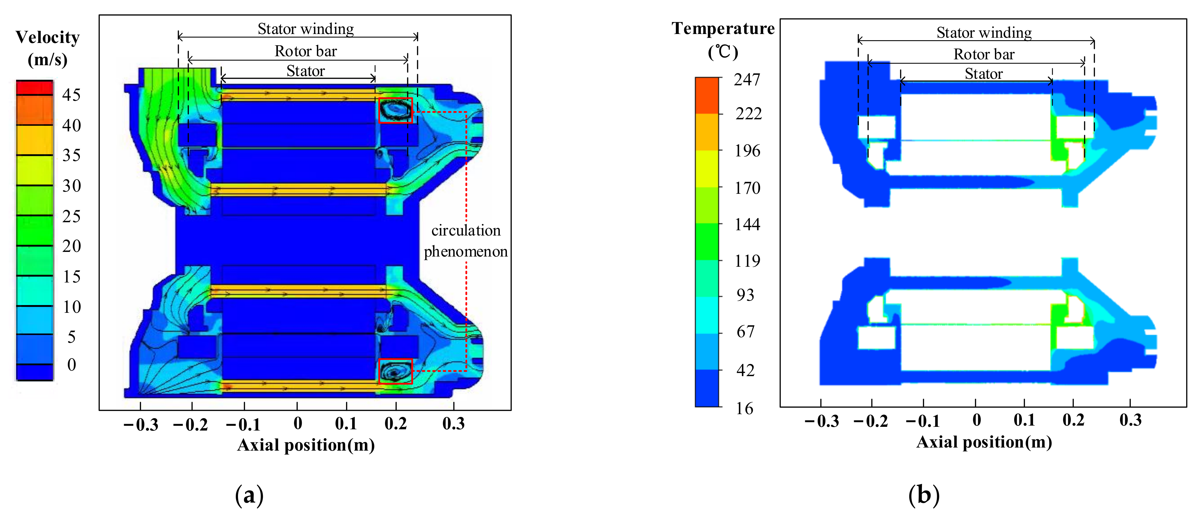
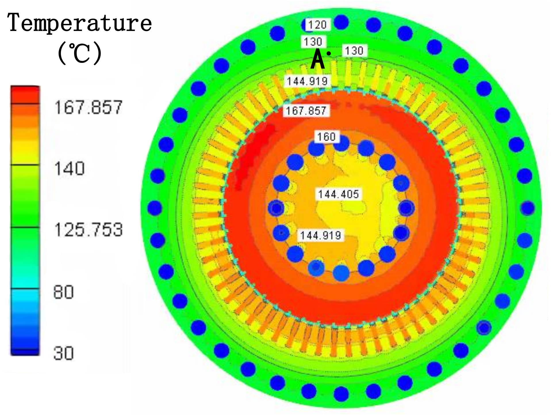
3. Simulation and Analysis of Original Ventilation Model

The original ventilation model is simulated. Figure 3 shows the velocity, fluid trace, and temperature distribution of air in the axial section. It can be seen that after the fluid flows in through the air inlet, the wind velocity in the stator ventilation holes and the rotor ventilation holes is relatively high with its maximum velocity reaching 44.19 m/s, and there is a circulation phenomenon between the end of the stator winding near the air outlet and the motor cavity. In terms of temperature, the temperature in the inlet cavity and the stator and rotor ventilation hole is low, while the temperature in the air gap is relatively high, and the highest temperature occurs in the air domain at the end of the rotor bar.
Figure 4 shows the temperature distribution of each part, the overall maximum temperature is located on the rotor bar, and the temperature of each part gradually increases from the air inlet side to the air outlet side.
To verify the correctness of the simulation results, point A of the radial section is put to comparative analysis, as shown in Figure 5. Point A is located at the stator yoke near the bottom of the slot. Using the experimental device shown in Figure 6, the temperature rise is measured under the condition of ambient temperature 16 °C, humidity 70.1%, and pressure 1906 Pa. The experimental results show that the temperature rise of point A is 110.6 °C, the static pressure of the inlet is 1906 Pa, and the dynamic pressure of the inlet is 727 Pa. The simulated results obtained at the same measurement position with the same motor size are as follows: the temperature rise is 114 °C; the static pressure is 1807 Pa; and the dynamic pressure is 694 Pa. Therefore, the errors of temperature, static pressure, dynamic pressure are approximately 3%, 5.2%, 4.5% respectively, which indicates the correctness of the simulation results.

4. Analysis of Motor Temperature Field and Fluid Field under Different Stator Ventilation Structures

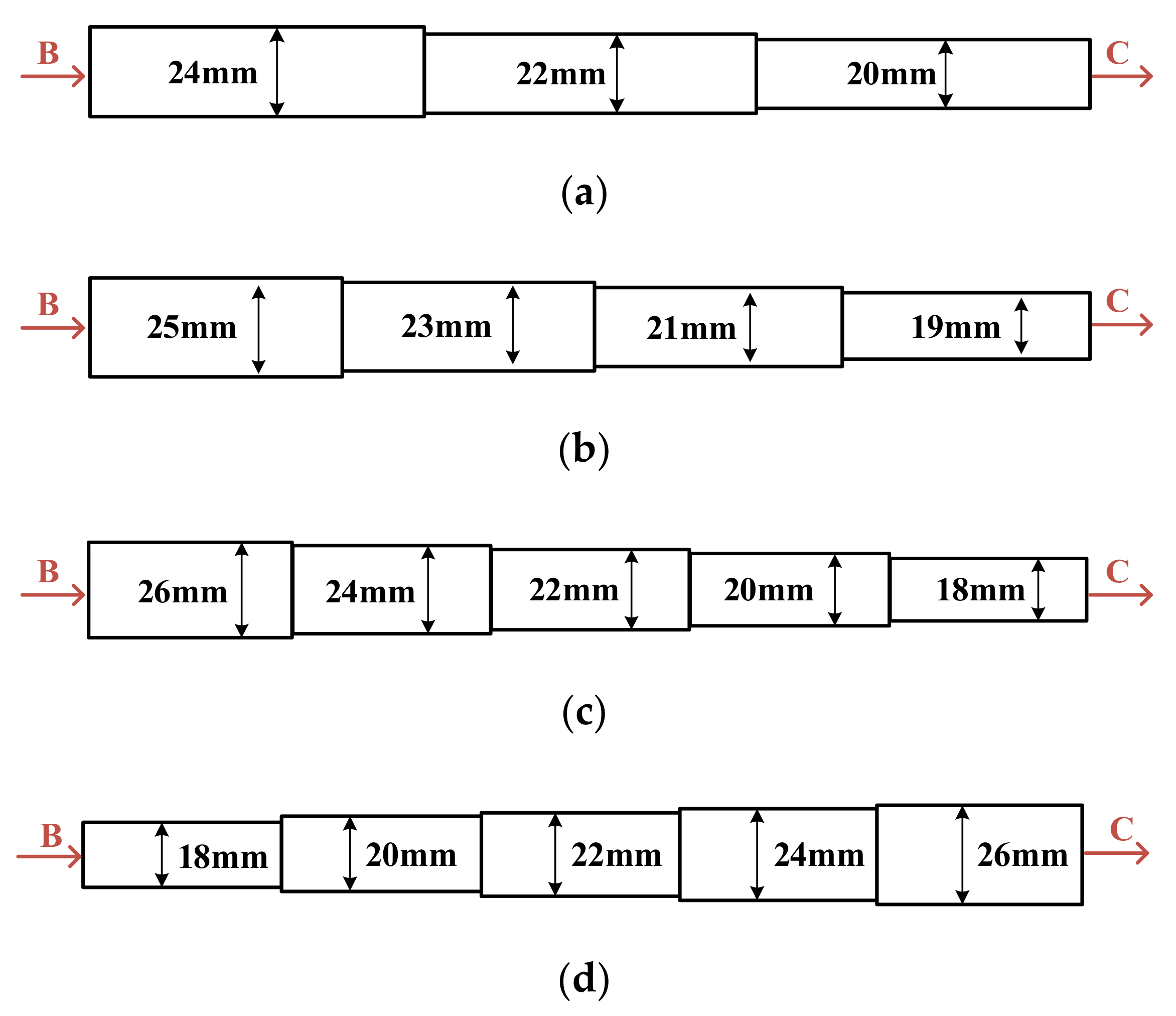
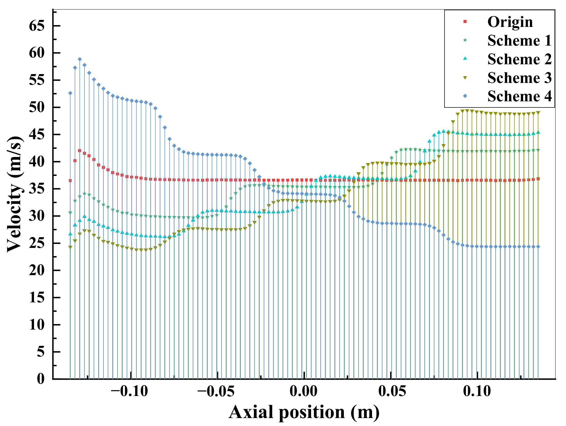
4.1. Analysis of the Nonlinear Variable Cross-Section Stator Ventilation Structure

To balance the motor axial temperature and reduce the temperature rise of the stator windings, four kinds of nonlinear variable cross-section segmented cylindrical stator ventilation structures are proposed. These structures are modified from a cylindrical ventilation hole with a cross-sectional diameter of 22 mm under the premise that the axial length and radial position of the original ventilation model remain unchanged, and the purpose of this treatment is to keep the stator ventilation volume unchanged as much as possible. The structure of schemes with different segment numbers is shown in Figure 7, and it can be seen that the fluid flows from end B to end C, in which the schemes 1–3 all have a large diameter of ventilation on the inlet side and a small diameter of ventilation on the outlet side, while scheme 4 is the opposite.
The models of nonlinear variable cross-section cylindrical ventilation holes with different segment numbers are simulated. After the iterative calculation converges, the temperature results of each part of the motor are obtained. Figure 8 shows the maximum temperature of the motor each part, which appears on the side of the outlet, and the rotor bar tops the motor components in maximum temperature. From Figure 8, it can be observed that the models with a nonlinear variable cross-section stator ventilation structure outperform the original ventilation in cooling effect, and each part of the motor sees a reduction in maximum temperature. schemes 1–3 show that with the increase of the number of segments, the maximum temperature of each part of the motor shows a downward trend, while the cooling effect of scheme 3 is the most effective. Compared with the original ventilation model, the maximum temperatures of the stator winding, stator core, slot insulation, rotor bar, and rotor core of scheme 3 have dropped by 4.8 °C, 4.5 °C, 4.6 °C, 18.1 °C, and 17.6 °C, respectively. In addition, when comparing scheme 3 with scheme 4, the stator winding, stator core, and rotor bar in scheme 4 all show a rise in maximum temperature, indicating that the ventilation structure of scheme 4 is not advisable, and the most competitive option is the cooling scheme with the large diameter ventilation hole on the inlet side and the small diameter ventilation hole on the outlet side.
The velocity distribution of schemes 1–4 is shown in Figure 9. From a horizontal comparison, the wind velocity of each scheme is higher before the axial position −0.125 m, as a consequence of the fluid flowing from the inlet to the stator ventilation holes at a higher pressure. The axial wind velocity of the original model largely remains identical, but schemes 1–4 shows an obvious jump in wind velocity at the segment, and the wind velocity appears to be centrally symmetrical. From a longitudinal perspective, compared with the original model, the wind velocities near the inlet of schemes 1–3 all decrease, while the velocities near the outlet all increase, and as the number of segments increases, the maximum velocity increases significantly. The highest temperature of the motor appears on the side close to the air outlet, and the wind velocity at the air outlet is ranked as follows: scheme 3 > scheme 2 > scheme 1, scheme 3 shows the best cooling effect.

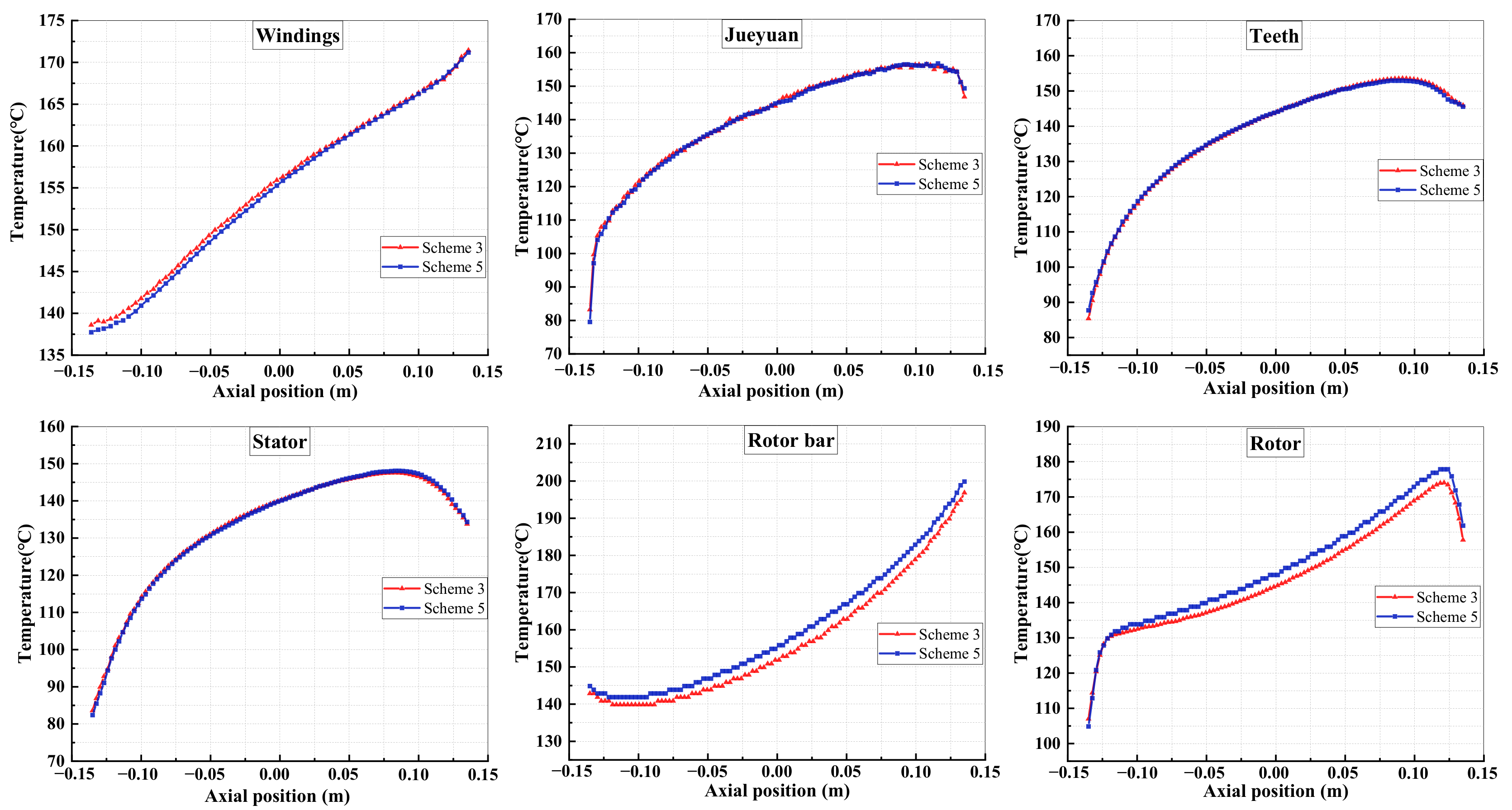
4.2. Analysis of the Linear Variable Cross-Section Stator Ventilation Structure

To further investigate the influence of variable cross-section stator ventilation hole on motor temperature, the five-segment nonlinear variable cross-section cylindrical stator ventilation hole described in scheme 3 is turned into a linear variable cross-section truncated cone-shaped stator ventilation hole, that is, the cross-sectional diameter increases linearly from the small diameter of 18 mm to the large diameter of 26 mm. The structure is shown in Figure 10, and this scheme is defined as scheme 5.
The model of scheme 5 is simulated and analyzed, and the results obtained. Figure 11 show the temperature comparison in scheme 3 and scheme 5. It can be seen that the temperature of each part of the motor increases from the inlet side to the outlet side, and the reason is that the wind temperature on the air inlet side is lower, and the wind has a strong ability to take away heat. Specifically, the temperature of the stator winding near the inlet side of scheme 5 is slightly lower than that of scheme 3, while the temperature is largely identical in insulation, stator teeth, and stator core. For the rotor core and rotor bar, the temperature of scheme 3 is 2–3 °C lower than scheme 5.
Figure 12 shows the variation of wind velocity with axial position in the stator and rotor ventilation holes respectively. For the fluid in the stator ventilation hole, the velocity near the inlet side in scheme 5 is larger than that of scheme 3, but the average wind speed near the outlet side in scheme 3 is larger, which is consistent with the temperature change trend of the stator winding. For the fluid in the rotor ventilation hole, the wind speed of scheme 3 is always higher than that of scheme 5, so the temperature of the rotor part of scheme 3 is slightly lower.
A comprehensive comparison of scheme 3 and scheme 5 shows that the temperature rise of each part of the motor is not significantly improved by the linear variable cross-section stator ventilation hole, and the temperature of the rotor increases slightly. Considering that the production process of the linear variable cross-section is more difficult and the production cost is higher, the nonlinear variable cross-section ventilation hole is more preferable.

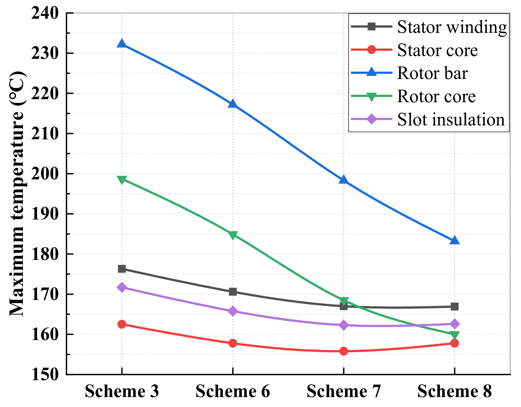
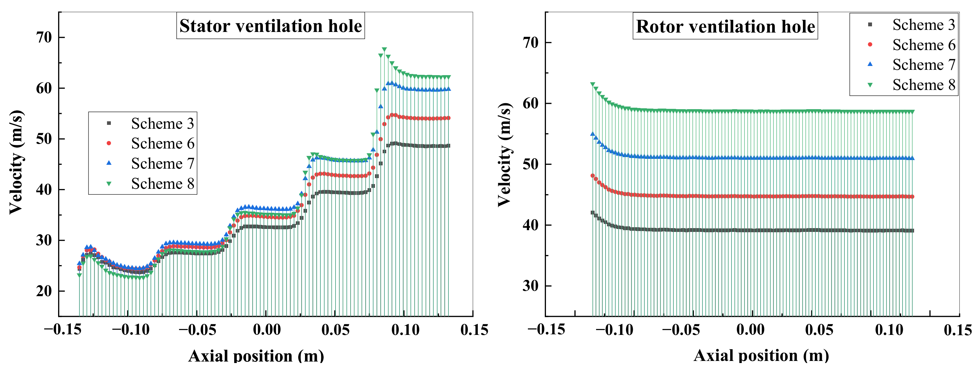
4.3. Analysis of Stator Ventilation Structure with Varying Cross-Sectional Diameter

As the cooling effect of the nonlinear variable cross-section stator ventilation hole is better, the structure of the nonlinear variable cross-section was further explored. Based on scheme 3, the cross-sectional diameter of the ventilation hole was changed to explore its influence on motor temperature. The detailed schemes are shown in Table 3.
The models of schemes 6–8 are simulated, and the results are shown in Figure 13. It can be seen from Figure 13 that changing the cross-sectional diameter of the ventilation holes can significantly reduce the motor temperature. Among these components, the temperature of the rotor bar and the rotor core decreases linearly, and the temperature of the stator decreases before it stabilizes. For the stator winding, the cross-sectional diameter between every two adjacent schemes is 2 mm, but the temperature change rate is quite different: the maximum temperature decreases by 3.2% from scheme 3 to scheme 6; the maximum temperature decreases by 2.1% from scheme 6 to scheme 7; and the maximum temperature decreases by 0.6% from scheme 7 to scheme 8. In other words, on the basis of the cross-sectional diameter of ventilation holes in scheme 7, if the cross-sectional diameter is further reduced, the stator winding does not show an obvious variation trend in the maximum temperature.
The wind velocity variation is shown in Figure 14. It can be seen that the velocity difference of the stator ventilation hole between the schemes is small near the air inlet side. With the increase of the axial position, the smaller the cross-sectional diameter, the faster the wind velocity increases, while the maximum velocity difference is about 20 m/s. For the fluid in the rotor ventilation hole, the wind speed varies greatly among the various schemes, and as the diameter decreases, the wind speed increases faster. Figure 15 shows the change of the air mass flow in the stator and rotor ventilation holes. It can be seen that as the diameter decreases, the mass flow in the stator ventilation holes decreases a lot, while the mass flow in the rotor ventilation holes increases greatly. In summary, the decrease of the stator ventilation hole diameter leads to an increase of wind speed, but a decrease of mass flow, therefore, the temperature variation range of the stator is relatively small. However, the wind speed and the mass flow of the rotor ventilation hole both increase, resulting in a significant decrease in rotor temperature. However, when the stator ventilation hole cross-sectional diameter is reduced to a certain value, for example, when it is reduced to the hole diameter of scheme 7, the increasing trend of the wind velocity in the stator ventilation holes will slow down, causing the mass flow in the stator vents to continue to decrease but in the rotor vents to continue to increase, which further leads to the substantial increase of wind speed in the rotor ventilation holes, so the temperature of the rotor will continue to decline.
A comprehensive comparison of schemes 3, 6, 7, and 8 shows that schemes 3 and 6 have higher temperatures, while a comparison of scheme 8 with scheme 7 indicates that the temperature difference of the stator part between the two schemes is very small and the rotor temperature of scheme 8 is lower. However, from the perspective of motor lightweight and reducing stator winding temperature rise, scheme 7 can effectively ensure a heat dissipation effect while the cross-sectional diameter is larger, which can effectively reduce the motor weight; therefore, the structure of scheme 7 is better.

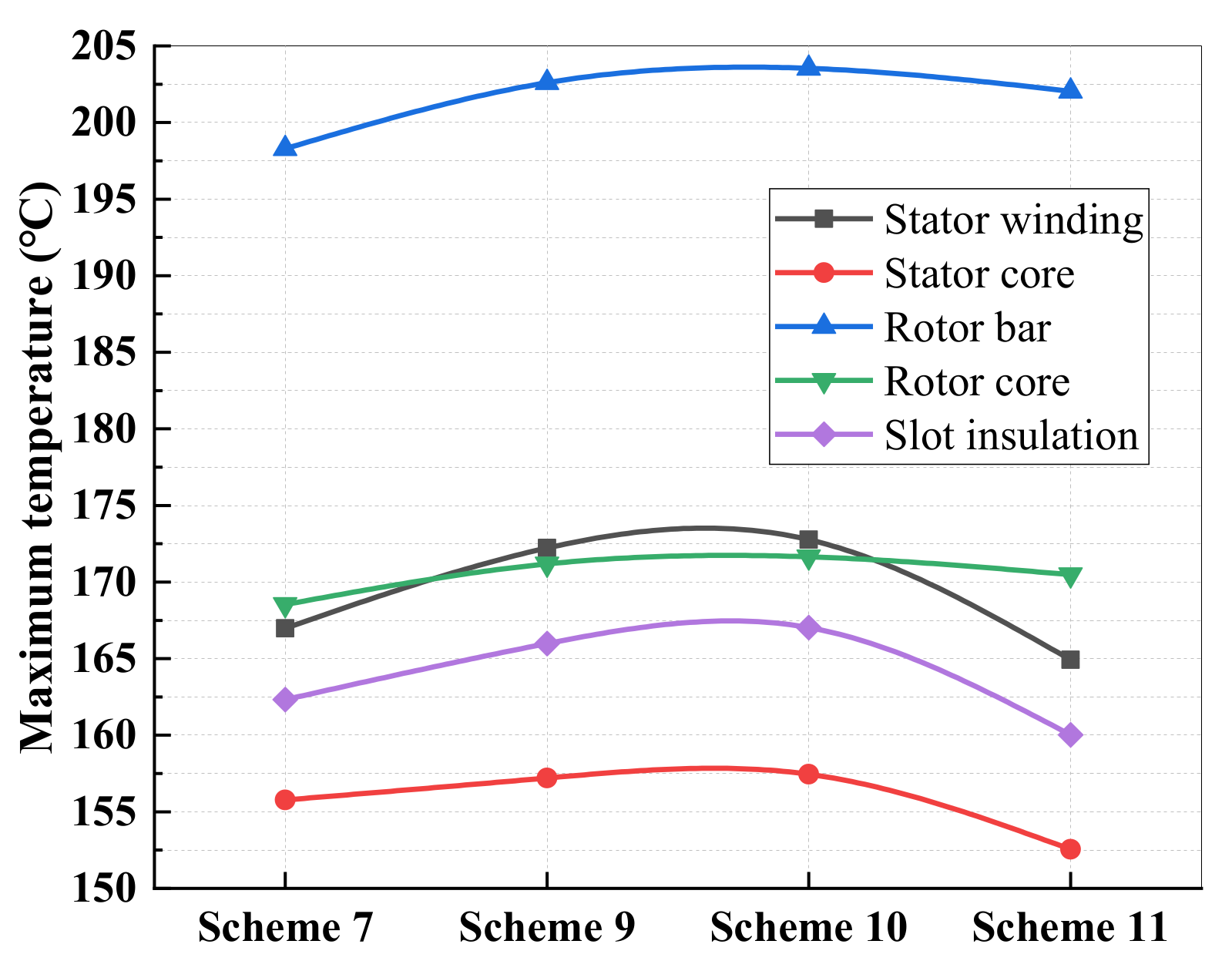
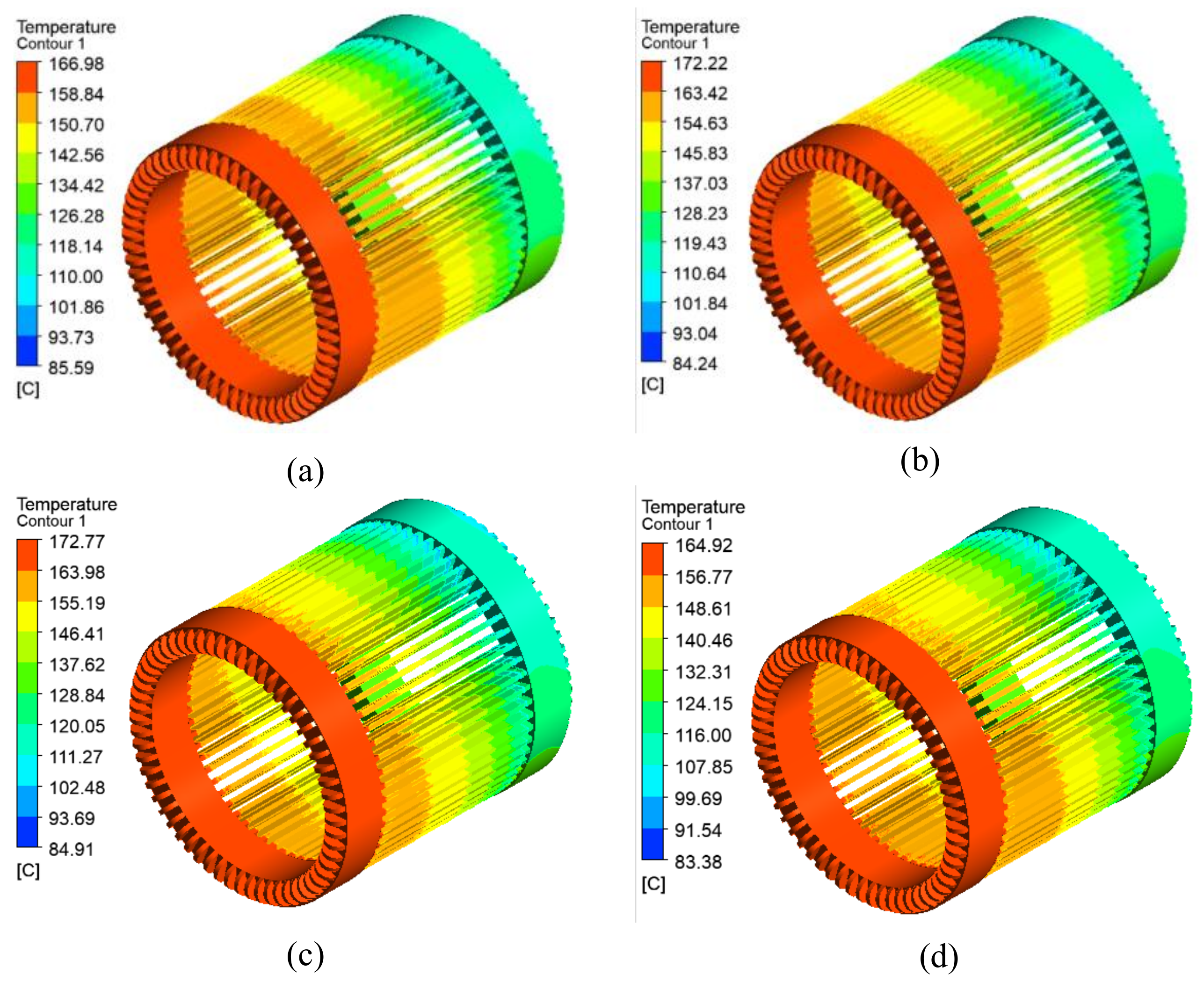
4.4. Analysis of Stator Ventilation Structure with Varying Radial Position

Based on the cross-sectional diameter of the ventilation hole in scheme 7, the radial position changed and its influence on the motor temperature was analyzed. The schematic diagram of the radial position is shown in Figure 1b and the scheme of the radial position variation is shown in Table 4.
The above schemes are simulated, and the results of the stator winding temperature are shown in Figure 16. It can be seen that from scheme 7 to scheme 11, that is, as the radial position decreases, the temperature distribution of each part shows the same trend, with both first increasing and subsequently decreasing.
To study the temperature of stator winding in detail, the temperature distribution was obtained and is shown in Figure 17. The axial temperature distribution trend of the stator winding is consistent, and the highest temperature appears at the end of the stator winding near the air outlet. In order to explore the reasons for this change, the wind speed near the highest temperature was extracted for comparative analysis, and the results are shown in Figure 18. It can be seen that the fluid above the ends of the windings is circulating. In scheme 7, the fluid flows back from the stator ventilation hole at a relatively high wind speed, which has a better cooling effect on the winding ends. scheme 9 is similar to scheme 7, but the circulation wind speed and radius are smaller. In scheme 10, two circulation loops are formed after the fluid flows out of the stator ventilation hole, but the circulation radius near the end of the winding is very small, which leads to a poor cooling effect at the end of the winding. scheme 11 is closest to the stator winding, the fluid flows to the end of the stator winding at a higher wind speed after the stator ventilation hole, therefore, the cooling effect of this scheme is the best.

5. Conclusions

In this paper, a fluid-structure coupling simulation of a 600-kW high-speed train induction motor was performed, and the following conclusions obtained:
(1)
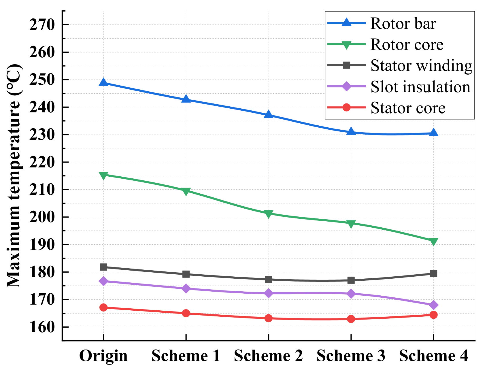
The cooling effect of the nonlinear variable cross-section cylindrical stator ventilation structure is more effective than that of the original ventilation structure, and with an increase in the number of segments, the temperature of each part of the motor shows a downward trend.
(2)
Under the same cross-sectional diameter, the cooling effect of the linear variable cross-section ventilation hole shows a small difference compared to that of the nonlinear variable cross-section ventilation hole. However, making a linear variable cross-section hole is technically challenging and the cost is also very high, while the nonlinear variable cross-section hole can be realized through stator core splicing, so the nonlinear cross-section ventilation hole is more desirable.
(3)
As the cross-sectional diameter of the stator ventilation hole decreases, the temperature of each part of the motor drops significantly. However, when the diameter is reduced to a certain value, the increasing trend of the wind velocity in the stator ventilation hole slows down, and the temperature of the stator changes only slightly. If the diameter is continuously reduced, the wind velocity in the rotor ventilation hole will increase, and the temperature of the rotor will continue to decrease.
(4)
The maximum temperature appears on the side of the air outlet, and it is greatly affected by the circulation wind speed and the circulation radius at the end. When the ventilation holes are close to the winding, the air from the stator ventilation holes can directly cool the end of the winding, which has a better dissipation effect.
(5)
By gradually attempting to identify a better scheme, the optimal stator ventilation structure is obtained. Compared to the original ventilation model, the maximum temperatures of the stator winding, stator core, rotor bar, rotor core, and slot insulation are reduced by 17.13 °C, 14.56 °C, 46.53 °C, 43.81 °C, and 16.56 °C, respectively. The cooling effect is obvious, and the heat dissipation capacity of the motor is significantly enhanced.

Author Contributions

Conceptualization, J.C. and H.Y.; methodology, J.C.; software, H.Y. and Y.W.; validation, J.C., H.Y., and D.L.; resources, J.C. and W.L.; writing—original draft preparation, H.Y.; writing—review and editing, J.C. and D.L.; visualization, H.Y. and Y.W.; supervision, W.L. All authors have read and agreed to the published version of the manuscript.

Funding

This research was funded by the Fundamental Research Funds for the Central Universities, grant number 2019JBM060.

Institutional Review Board Statement

Not applicable.

Informed Consent Statement

Not applicable.

Data Availability Statement

Not applicable.

Conflicts of Interest

The authors declare no conflict of interest.

References

  1. Cao, J.; Li, W.; Zhang, Y.; Zhang, X.; Jiang, Y.; He, Y. Analyses on heat transfer and fluid flowing in a traction motor used in high-speed CRH. In Proceedings of the 2015 International Conference on Electrical Systems for Aircraft, Railway, Ship Propulsion and Road Vehicles (ESARS), Aachen, Germany, 3–5 March 2015; pp. 1–8. [Google Scholar]
  2. Chen, J.; Ma, J.; Fang, Y.; Li, T.; Li, J. Analysis of temperature field distribution of magnetic-fluid bearing for high-speed trains. In Proceedings of the 2015 18th International Conference on Electrical Machines and Systems (ICEMS), Pattaya, Thailand, 25–28 October 2015; pp. 620–623. [Google Scholar]
  3. Ding, S.; Li, H. Investigation of characteristics of fluid flow pattern for air-cooled motor. In Proceedings of the 2016 IEEE 11th Conference on Industrial Electronics and Applications (ICIEA), Hefei, China, 5–7 June 2016; pp. 2044–2048. [Google Scholar]
  4. Huang, Z.; Fang, J.; Liu, X.; Han, B. Loss calculation and thermal analysis of rotors supported by active magnetic bearings for high-speed permanent-magnet electrical machines. IEEE Trans. Ind. Electron. 2015, 63, 2027–2035. [Google Scholar] [CrossRef]
  5. Chu, S.; Liang, D.; Jia, S.; Liang, Y. Research and Analysis on Design Characteristics of High Temperature and High-Speed Permanent Magnet Motor. In Proceedings of the 2020 International Conference on Electrical Machines (ICEM), Gothenburg, Sweden, 23–26 August 2020; Volume 1, pp. 2452–2456. [Google Scholar]
  6. Gai, Y.; Kimiabeigi, M.; Chong, Y.; Widmer, J.; Deng, X.; Popescu, M.; Steven, A. Cooling of automotive traction motors: Schemes, examples, and computation methods. IEEE Trans. Ind. Electron. 2018, 66, 1681–1692. [Google Scholar] [CrossRef] [Green Version]
  7. Bourgault, A.; Roy, P.; Ghosh, E.; Kar, N. A Survey of Different Cooling Methods for Traction Motor Application. In Proceedings of the 2019 IEEE Canadian Conference of Electrical and Computer Engineering (CCECE), Edmonton, AB, Canada, 5–8 May 2019; pp. 1–4. [Google Scholar]
  8. Huang, Z.; Nategh, S.; Lassila, V.; Alaküla, M.; Yuan, J. Direct oil cooling of traction motors in hybrid drives. In Proceedings of the 2012 IEEE International Electric Vehicle Conference, Greenville, SC, USA, 4–8 March 2012; pp. 1–8. [Google Scholar]
  9. Zhang, Y.; Ruan, J.; Huang, T.; Yang, X.; Zhu, H.; Yang, G. Calculation of temperature rise in air-cooled induction motors through 3-D coupled electromagnetic fluid-dynamical and thermal finite-element analysis. IEEE Trans. Magn. 2012, 48, 1047–1050. [Google Scholar] [CrossRef]
  10. Chen, Y.; Chen, W.; Zhou, J.; Fang, Y.; Yao, Y. Multi-field coupled analysis of a permanent magnet synchronous motor: Application to high speed rail traction. In Proceedings of the 2016 Eleventh International Conference on Ecological Vehicles and Renewable Energies (EVER), Monte Carlo, Monaco, 6–8 April 2016; pp. 1–6. [Google Scholar]
  11. Wang, X.; Gao, W. Research on cooling and improved designing of inverter-asynchronous motor compositive system. In Proceedings of the 2011 International Conference on Electrical Machines and Systems, Beijing, China, 20–23 August 2011; pp. 1–6. [Google Scholar]
  12. Yang, K.; Feng, Y. Design of novel spiral magnetic poles and axial-cooling structure of outer-rotor PM torque motor. IEEE Trans. Appl. Supercond. 2010, 20, 838–841. [Google Scholar] [CrossRef]
  13. Zhang, Y.; Sun, M.; Ruan, J.; Huang, T. Ventilation Structure Improvement of Large Motors Using 3-D Multi-Physical Coupled-Field Finite-Element Analysis. In Proceedings of the 2012 Sixth International Conference on Electromagnetic Field Problems and Applications, Dalian, China, 19–21 June 2012; pp. 1–4. [Google Scholar]
  14. Kim, S.C.; Kim, W.; Kim, M.S. Cooling performance of 25 kW in-wheel motor for electric vehicles. Int. J. Automot. Technol. 2013, 14, 559–567. [Google Scholar] [CrossRef]
  15. Cao, J.; Wu, Z.; Li, W.; Li, D.; Zhang, X.; Zhang, Y.; Huang, J. Influence of axial ventilation structures on electromagnetic field and heat transfer of traction motor used for high—Speed EMU. In Proceedings of the 2017 20th International Conference on Electrical Machines and Systems (ICEMS), Sydney, NSW, Australia, 11–14 August 2017; pp. 1–6. [Google Scholar]
  16. Li, W.; Li, J.; Li, D. Influence of variable section rotor ventilation ducts on temperature and fluid fields of a full air-cooled large hydro-generator rotor. Trans. China Electrotech. Soc. 2017, 32, 42–48. [Google Scholar]
  17. Tong, W.; Wu, S.; Tang, R. Totally enclosed self-circulation axial ventilation system design and thermal analysis of a 1.65-MW direct-drive PMSM. IEEE Trans. Ind. Electron. 2018, 65, 9388–9398. [Google Scholar] [CrossRef]
  18. Cao, Z.; Li, W.; Zhang, X.; Fan, Y.; Zeng, J. Influence of single/dual ventilation path on fluid field and temperature field of HVLSSR-PMSM with air-cooled hybrid ventilation systems. Energies 2018, 11, 1343. [Google Scholar] [CrossRef] [Green Version]
  19. Zhu, G.; Liu, X.; Li, L.; Chen, H.; Tong, W.; Zhu, J. Cooling system design of a high-speed PMSM based on a coupled fluidic-thermal model. IEEE Trans. Appl. Supercond. 2019, 29, 1–5. [Google Scholar] [CrossRef]
  20. Liu, W.; Li, W.; Luo, S.; Huang, X.; Li, D.; Li, Z.; Xu, G. Influence of a Novel Stator Teeth Internal Ventilation Structure on Air-Cooled Turbo-Generator Parameters and Stator Temperature. IEEE Access 2020, 8, 122422–122433. [Google Scholar] [CrossRef]
  21. Li, R.; Cheng, P.; Lan, H.; Li, W.; Gerada, D.; Hong, Y. Stator Non-Uniform Radial Ventilation Design Methodology for a 15 MW Turbo-Synchronous Generator Based on Single Ventilation Duct Subsystem. Energies 2021, 14, 2760. [Google Scholar] [CrossRef]
  22. Chen, Y.; Zhou, J.; Fang, Y.; Gao, Y.; Xia, Y. Multi-field coupling finite-element analysis of the temperature rise in permanent magnet synchronous motor applied for high speed train. In Proceedings of the 2016 19th International Conference on Electrical Machines and Systems (ICEMS), Chiba, Japan, 13–16 November 2016; pp. 1–4. [Google Scholar]
  23. Ding, S.; Li, S. Research of heat transfer characteristic for PMSM with two-way ventilation structure. In Proceedings of the 2016 IEEE 11th Conference on Industrial Electronics and Applications (ICIEA), Hefei, China, 5–7 June 2016; pp. 2206–2210. [Google Scholar]
  24. Li, D.; Wen, Y.; Li, W.; Feng, B.; Cao, J. Three-dimensional temperature field calculation and analysis of an axial-radial flux-type permanent magnet synchronous motor. Energies 2018, 11, 1208. [Google Scholar] [CrossRef] [Green Version]
  25. Li, W.; Cao, Z.; Zhang, X. Thermal Analysis of the Solid-Rotor Permanent Magnet Synchronous Motors with Air-cooled Hybrid Ventilation Systems. IEEE Trans. Ind. Electron. 2021. [Google Scholar] [CrossRef]
  26. Schrittwieser, M.; Biro, O.; Farnleitner, E.; Kastner, G. Characterizing the convective heat transfer on stator ventilation ducts for large hydro generators with a neural network. COMPEL Int. J. Comput. Math. Electr. Electron. Eng. 2015, 34, 1522–1536. [Google Scholar] [CrossRef]
  27. Guo, H.; Ding, Q.; Song, Y.; Tang, H.; Wang, L.; Zhao, J. Predicting temperature of permanent magnet synchronous motor based on deep neural network. Energies 2020, 13, 4782. [Google Scholar] [CrossRef]
  28. Versteeg, H.K.; Malalasekera, W. An Introduction to Computational Fluid Dynamics: The Finite Volume Method; Pearson Education: London, UK, 2007. [Google Scholar]
  29. Ding, X.; Liu, B. Fluent 17.0 Fluid Simulation Calculation from Elementary to Proficient; Tsinghua University Press: Beijing, China, 2014. [Google Scholar]
  30. Tao, L.; Zhang, Y.; Liang, Y.; Qiang, A.; Haishi, D. Thermal Analysis of the Yokeless and Segmented Armature Axial Flux In-wheel Motor. In Proceedings of the 2020 International Conference on Artificial Intelligence and Computer Engineering (ICAICE), Beijing, China, 23–25 October 2020; pp. 449–452. [Google Scholar]
  31. Fu, X. Electromagnetic Field Computation and Operating Characteristic Analysis for a Permanent Magnet-Inductor Hybrid Excitation Generator. Ph.D. Thesis, Harbin Institute of Technology, Harbin, China, 2011. [Google Scholar]
  32. Tai, Y.; Liu, Z. Analysis on three-dimensional transient temperature field of induction motor. Proc. CSEE 2010, 30, 114–120. [Google Scholar]
Figure 1. Structure of the induction traction motor. (a) Three-dimensional structure of the motor; (b) Motor structure in the radial and axial sections.
Energies 14 05249 g001
Figure 2. Mesh of solution region.
Energies 14 05249 g002
Figure 3. Velocity and temperature distribution of air in the radial section of the original model. (a) Velocity distribution of air; (b) Temperature distribution of air.
Energies 14 05249 g003
Figure 4. Temperature distribution of the original ventilation model. (a) Winding; (b) Stator core; (c) Insulation; (d) Rotor bar; (e) Rotor.
Energies 14 05249 g004
Figure 5. Temperature distribution in the radial section of the original ventilation model.
Energies 14 05249 g005
Figure 6. Test bench for motor experiments.
Energies 14 05249 g006
Figure 7. Structure of nonlinear variable cross-section stator ventilation hole. (a) scheme 1; (b) scheme 2; (c) scheme 3; (d) scheme 4.
Energies 14 05249 g007
Figure 8. Temperature comparison of nonlinear variable cross-section stator ventilation schemes.
Energies 14 05249 g008
Figure 9. Axial velocity comparison of nonlinear variable cross-section stator ventilation schemes.
Energies 14 05249 g009
Figure 10. Structure of linear variable section stator ventilation hole.
Energies 14 05249 g010
Figure 11. Temperature comparison of nonlinear variable cross-section and linear variable cross-section stator ventilation hole.
Energies 14 05249 g011
Figure 12. Velocity comparison of nonlinear variable cross-section and linear variable cross-section stator ventilation holes.
Energies 14 05249 g012
Figure 13. Temperature comparison under the scheme with varying cross-sectional diameter.
Energies 14 05249 g013
Figure 14. Velocity comparison under the scheme with varying cross-sectional diameter.
Energies 14 05249 g014
Figure 15. Ventilation rate comparison under the scheme with varying cross-sectional diameter.
Energies 14 05249 g015
Figure 16. Temperature comparison under the scheme with varying cross-sectional diameter.
Energies 14 05249 g016
Figure 17. Temperature comparison of the stator winding under schemes with varying radial position. (a) scheme 7; (b) scheme 9; (c) scheme 10; (d) scheme 11.
Energies 14 05249 g017
Figure 18. Velocity comparison near the outlet under schemes with varying radial position. (a) scheme 7; (b) scheme 9; (c) scheme 10; (d) scheme 11.
Energies 14 05249 g018
Table 1. Parameter of induction motor.
ParameterValue
Rated Power600 (kW)
Rated Voltage2730 (V)
Rated Current155 (A)
Current Density5.47 (A/mm2)
Frequency155.55 (Hz)
Speed4636 (r/min)
Efficiency94%
Power Factor0.87
Stator Core Length270 (mm)
Stator Outer Diameter555 (mm)
Stator Inner Diameter330 (mm)
Air gap length1.8 (mm)
Rotor Inner Diameter330 (mm)
Number of stator slots60
Number of rotor slots48
The radial position of the stator ventilation hole257.5 (mm)
Table 2. Loss distribution of induction motor.
ParameterValue
Stator Winding5.814 (kW)
Stator Yoke5.285 (kW)
Stator Teeth2.667 (kW)
Rotor Bar3.900 (kW)
Rotor0.42 (kW)
Additional loss3.159 (kW)
Mechanical loss7.56 (kW)
Table 3. Stator ventilation schemes with varying cross-sectional diameter.
SchemeCross-Sectional Diameter (mm)Radial Position (mm)
624-22-20-18-16257.5
722-20-18-16-14257.5
820-18-16-14-12257.5
Table 4. Stator ventilation schemes with varying radial position.
SchemeCross-Sectional Diameter (mm)Radial Position (mm)
922-20-18-16-14247.5
1022-20-18-16-14237.5
1122-20-18-16-14227.5
Publisher’s Note: MDPI stays neutral with regard to jurisdictional claims in published maps and institutional affiliations.

