Abstract
A small-scale organic Rankine cycle (ORC) with kW-class power output has a wide application prospect in industrial low-grade energy utilization. Increasing the expansion pressure ratio of small-scale ORC is an effective approach to improve the energy efficiency. However, there is a lack of suitable expander for small-scale ORC that can operate with a high efficiency under the condition of large expansion pressure ratio and small mass flow rate. Aiming at the design of high-efficiency axial-flow turbine in small ORC system, this paper investigates the performance of a kW-class axial-flow turbine and proposes a method for efficiency improvement. First, the preliminary design of an axial-flow turbine is conducted to optimize the geometric parameters and aerodynamic parameters. Then, the effects of tip clearance and trailing edge thickness on turbine performance are analyzed under design and off-design conditions. The results show that the efficiency of the two-stage or three-stage turbine is evidently better than that of the single-stage one. The output power and efficiency of the three-stage turbine are close to that of the two-stage turbine while the speed is lower. Meanwhile, the trailing edge loss and leakage loss can be significantly reduced via reducing the trailing edge thickness and tip clearance, and thus the turbine efficiency can be improved significantly. The estimated efficiency arrives at 0.82, which is 33% higher than that of the conventional turbine. Considering the limitation of turbine speed, three-stage axial-flow turbine is a feasible choice to improve turbine efficiency in a small-scale ORC.
1. Introduction
Improving energy efficiency is important to achieve the goal of carbon emission peak and carbon neutrality. A large amount of low-grade energy is wasted in industrial processes, and it has great potential to recover this part of energy via organic Rankine cycle (ORC) technology. ORC systems have been used in geothermal energy utilization [1,2], solar power generation [3,4], industrial waste heat reclaim [5], internal combustion engine waste heat recovery [6,7,8], etc.
Turbine expander has a high efficiency with compact structure and is widely used in ORC systems. Generally, turbines are divided into radial and axial flow types according to the geometry of flow passage. The radius along the rotor flow passage of radial turbine changes significantly, while that in axial flow turbines varies slightly [9]. For ORC applications, most investigations are concentrated on radial turbine. For instance, a radial-flow turbine with variable vane [10,11] was designed to adapt off-design conditions. The constraints of mechanical stress and vibration need to be considered during the design process [12]. A two-stage radial turbine was designed for a small ORC industrial plant [13]. To improve turbine load and increasing pressure ratio, a back-bent radial turbine [14] and a novel two-sided turbine [15] were proposed. Based on a 150 °C heat source, Fiaschi et al. [16] designed a 50 kW radial-flow turbine, and the incident angle of the rotor blade maintained positive to increase the load and improve the compactness. In addition, the radial outflow turbine had been proposed [17]. However, for the design of radial turbines with a high pressure ratio and a small mass flow, the gap between rotor blades is very small, which is a huge challenge in the actual engineering manufacturing.
Turbine is the key component responsible for power output in an ORC. Its efficiency and geometry are affected by working fluid and the operating parameters. For a specific heat source, as the evaporating temperature increases, the mass flow rate declines and the pressure ratio increase, causing an increment of leaving-velocity loss. On the contrary, a higher mass flow rate results in a larger axial velocity at the outlet of the rotor blade, also leading to a greater leaving-velocity loss. Therefore, there is an optimal evaporation temperature maximizing the turbine efficiency. The geometrical parameters of the turbine are greatly influenced by heat source conditions [18]. A study of Pan et al. [19] shows that the turbine efficiency decreased with the increase of heat source temperature, and the maximum efficiency difference reached 0.027. The selection of working fluid has an influence on turbine efficiency. For example, a maximum turbine efficiency of 0.808 was achieved for R123, while the efficiencies were only 0.714 and 0.697 for R600 and R600a, respectively [20]. Turbine geometry is also affected by the selection of working fluid. An investigation showed that the diameter at the inlet of rotor blade was 74.5 mm for R143a while it was 144.3 mm for n-pentane [21]. Apparently, geometric size will affect the cost and compactness of the system. In summary, the turbine performance is influenced by the operation parameters of ORC [22], and in turn it will affect the thermoeconomic performance of the system [23]. The heat-source temperature influences the optimal design of radial-inflow turbine. As the heat-source temperature increases, the optimal blade-loading coefficient rises, whilst the optimal flow coefficient reduces. Furthermore, passage losses are dominant in turbines for low-temperature applications. However, at higher heat-source temperatures, clearance losses become more severe owing to the reduced blade heights [24]. Therefore, the coupling relationship of turbine design with ORC system optimization is complicated and should be taken into account comprehensively.
Axial turbines are normally used for large-scale ORC systems. Meroni et al. [25] built a multi-stage axial-flow turbine model, and screened out important variables for turbine design through sensitivity analysis, useful for combined optimization with ORC system [26]. Later, targeted at waste heat utilization of marine diesel engine, Meroni et al. optimized a MW-class multistage axial-flow turbine [27]. Mikiele et al. [28] designed and analyzed five turbines based on an ORC for biomass energy with thermal power of 25–100 kW. The single-stage radial-flow turbine and two-stage axial-flow turbine could achieve the highest output power. The two-stage axial-flow turbine has a significantly lower rotational speed than the single-stage radial-flow turbine, but its geometric structure was more complex. Morgese et al. [29] proposed an optimization design procedure, which is able to rapidly come to the design of the turboexpander taking into account all the fluid dynamic and technical requirements. Quan et al. [30] designed an axial impulse turbine with the total-to-total isentropic efficiency of 77.46% for a high-temperature ORC. Witanowski et al. [31] conducted an optimization of an axial turbine for a small scale ORC, and the total-to-static efficiency of the turbine reached to 80.6%. Al Jubori et al. [32] proposed a three-dimensional multi-objective optimization model for turbine stage to improve turbine efficiency and ORC system performance, based on a low-temperature small-scale ORC application where the heat source temperature was less than 100 °C. Subsequently, a two-stage axial-flow turbine model was established [33], and the mean-line preliminary design method, three-dimensional CFD analysis, and ORC system thermodynamics model were integrated. The analysis showed that the two-stage axial-flow turbine had a higher efficiency than the single-stage turbine, indicating the potential application of two-stage axial flow turbine in low-temperature small-scale ORC. The performance comparison among the single-stage and two-stage axial turbines, radial-inflow turbine, and radial-outflow turbine [34] indicated that the two-stage axial-flow and radial-outflow turbine had higher efficiencies. Compared with single-stage radial-outflow turbine, single-stage axial-flow turbine may have higher efficiency with a smaller size [35]. Two micro single stage impulse axial turbines with output power of 15 kW and 12 kW were designed and the total-to-static efficiency of 65.0% and 73.4% were obtained, respectively [36]. The maximum isentropic efficiency of the small-scall cantilever turbines also could reach 76.8% [37].
For turbines with an output power of less than 20 kW should be specially designed to fulfil the efficient, light, and compact requirements. The blade height at the inlet of the turbine which is constrained by the associated operation pressure [38]. Therefore, some radial-outflow turbines [39] and radial-inflow turbines [40,41,42,43] were designed. The performance maps were strongly influenced by the pressure ratio, shroud-to-tip radius ratio for small-scale radial turbine [44]. A high-speed turbine generator including a supersonic radial turbine was developed and the maximum electric power arrived at 5.9 kW with a turbine power output of 10.1 kW [45]. The peak efficiency of the radial turbine was 35.2% under the experimental conditions [46]. A 5 kW inflow-radial turbine was designed, and the predicted turbine efficiency was 78.32% with a power of 4.8 kW using R600 as the working fluid [47]. The small-scale turbines mentioned previously are designed for ORCs with low-temperature sources, about 100 °C [32,33,34,35,42,43,47]. Most of them are radial turbines, and the pressures at the turbine inlet are not very high, 19.9 bar in [38], 0.392 bar in [39], 34.7 bar in [40], 18.1 bar in [41], 13.0 bar in [46], 7.9 bar in [45]. Such a low pressure is not suitable for a supercritical ORC. Furthermore, the improvement of expansion pressure ratio of radial turbine is limited. Therefore, it is necessary to explore the feasibility of axial-flow turbine for small-scale supercritical ORC. However, few studies concentrated on axial-flow turbines for such a small-scale ORC, especially under the conditions with a high inlet pressure as 6.0 MPa and a small mass flow rate just as the supercritical ORC required. A low mass flow rate of the working fluid and a high pressure at the turbine inlet require a high volume expansion ratio, which puts forward a great challenge to the design of high efficiency turbine. A multi-stage axial-flow turbine can achieve a high pressure ratio and maintain a small flow rate with a high efficiency. In this study, a preliminary design model of multi-stage axial-flow turbines is established and the feasibility for the design of small ORC turbines with a high pressure ratio and a mass low flow rate is explored. The aerodynamic optimization is conducted using the flow coefficient, load coefficient, and reaction degree as input variables. The corresponding geometry is determined under the design conditions. The main factors affecting the turbine efficiency are analyzed and a method is proposed to improve turbine efficiency by trailing edge thickness and reducing tip clearance. Then, the off-design performance is estimated. The results indicate that reducing trailing edge thickness and tip clearance can significantly improve turbine efficiency for small kW-class multi-stage axial-flow turbines.
2. Mathematical Model
The mean-line model is widely used in the preliminary design of turbine machinery. This model assumes that the flow parameters located at the mean radius in the flow passage can represent the mean value of the cross section, ignoring the variations of the parameters along the radial and circumferential directions. Although this method simplifies the real flow field and cannot reveal the details of the flow field parameters inside the turbine, it has a high accuracy in determining the overall performance of the turbine [9], and the calculation load is far less than that of three-dimensional CFD method. In this study, a multi-stage axial-flow turbine model is established based on the mean-line method based on the assumptions of repeated stage and equal expansion pressure ratio [48]. The repeated stage must meet three conditions:
where vx is the meridional flow velocity, and are the absolute speed angles at the inlet and outlet of the stage, respectively, rm is the average radius that divides the annular flow channel into two zones with equivalent area. According to the assumptions of the repeat stages, the absolute and relative speed angles at the stage inlet equal to that at the outlet, respectively.
vx = constant,
According to the equal expansion pressure ratio assumption, the total-to-total pressure ratio of each stage is determined by
where prtt is the pressure ratio of each stage, and n is the stage number of the turbine. A detailed description of the mean-line model can be referred to [49].
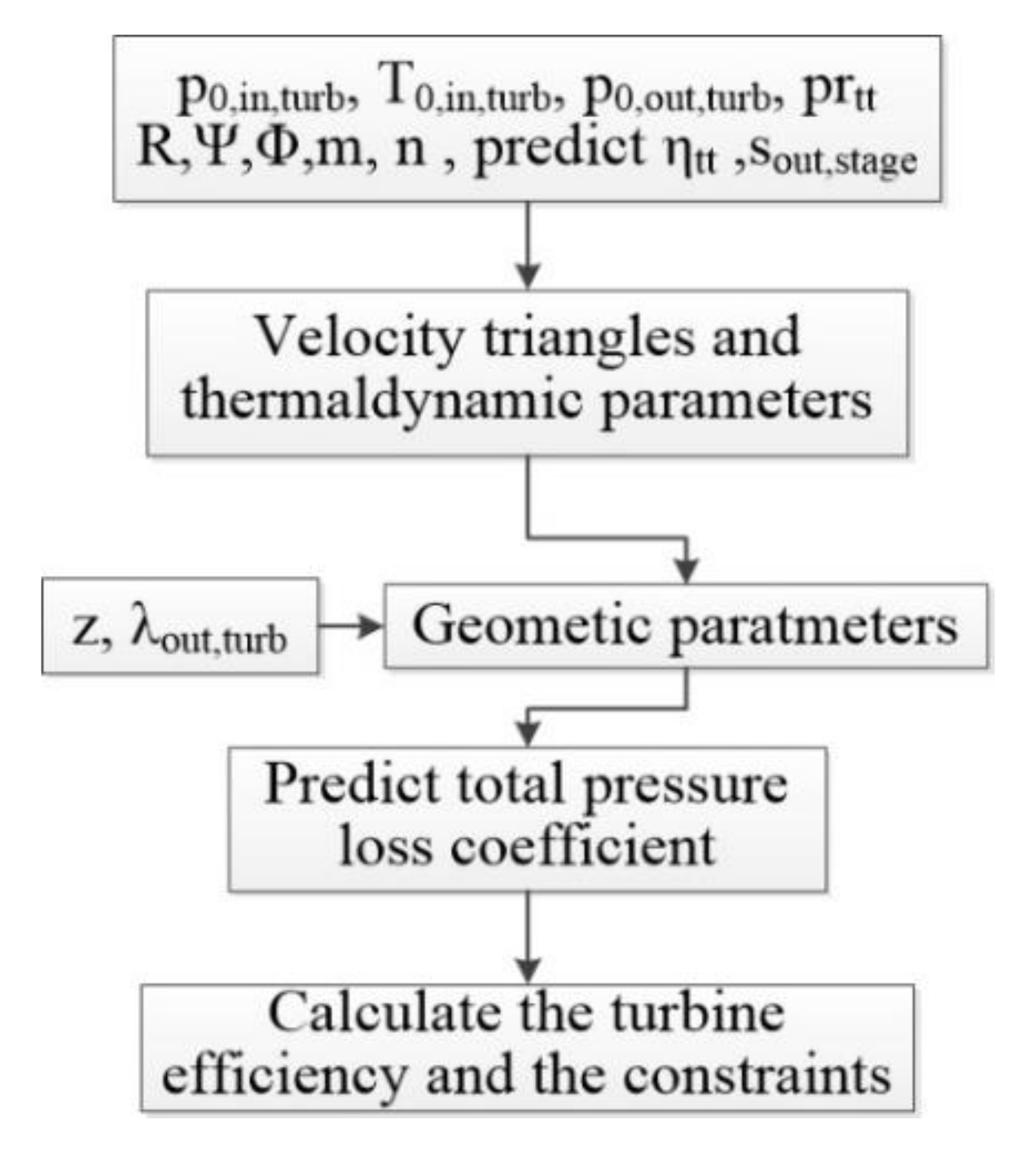
The input parameters of the preliminary optimization design model include the total temperature and total pressure at the turbine inlet, the total pressure at the turbine outlet, the mass flow rate through the turbine and the corresponding working fluid. The flow chart of the optimization model is shown in Figure 1. First, the entropy at the outlet of the cascade is determined according to the input parameters. The aerodynamic parameters at the inlet and outlet of the cascade and velocity triangle are obtained based on the optimization variables (i.e., flow coefficient, load coefficient and reaction degree of the first stage). The corresponding angles are calculated as follows.

Figure 1.
Flow chart of the designed turbine optimization model.
Next, the main geometric parameters of the cascade including the chord length of the blade, the pitch, and the average radius are determined according to the ratio of root and tip radius at the outlet of the last rotor blade and the number of blades in the blade row. Then, the total pressure loss coefficient of the blade row is estimated according to the geometric and aerodynamic parameters. In this study, the total pressure loss coefficient is obtained according to the empirical model summarized by Aunger [50], including airfoil loss, secondary flow loss, clearance loss, trailing edge loss, shock loss, and supersonic expansion loss. The total pressure loss coefficient is expressed by
where p0 is the total pressure, p is the static pressure, the subscripts in and out represent the inlet and outlet of the blade row, and rel represents the relative value. Since the rotor speed of stator blade is zero, its relative and absolute aerodynamic parameters are the same, and thus the relative value is used uniformly. Finally, the turbine efficiency with regard to nonlinear inequality constraints is calculated. The detailed nonlinear inequality constraints can be referenced in [49].
The design objective of the optimization model is the turbine efficiency. It is assumed that the kinetic energy at the outlet of the last rotor blade is recovered [51]. The turbine efficiency is defined as
where h represents enthalpy, v is the absolute velocity, the subscript 0 represents stagnation state, s denotes the isentropic process. The total enthalpy at the outlet of the turbine h0,out,turb is calculate according to the p0,out,turb and the optimized variable sout for the last stage. The static enthalpy at the outlet of the turbine is calculated according to the sin,turb which can be determined by the total pressure and temperature at the inlet of the turbine and the pout,turb, which is inferred after the velocity triangles are determined. The optimization objective function is expressed as below.
The preliminary design model is compiled into a MATLAB program, and the gradient descent optimization algorithm is adopted. The number of blades obtained from the optimization model might not be an integer. Then, the integer value close to the optimization solution is selected, and the enumeration method is used to re-optimize the entire calculation process. Finally, the number of blades with the highest turbine efficiency is obtained as the optimization result. Based on the geometric parameters of the optimized turbine, the aerodynamic parameters under off-design conditions are determined by using the total temperature, total pressure, and rotational speed of the turbine inlet as inputs while maintaining the static pressure at the turbine outlet under the same condition. The following equations are solved numerically to obtain to the aerodynamic parameters.
where is the guess value of the mass flow rate through the turbine stage, vx is the axial velocity, A is flow area, and d is the density of the working fluid.
3. Results
For small-scale ORC systems, studies have shown that supercritical ORC can significantly improve the energy efficiency. At this moment, the turbine operates under the conditions of a large pressure ratio and a small mass flow rate, and the design of efficient turbine becomes a difficulty. In this study, the input parameters for the turbine design are listed in Table 1. These parameters are the results from an investigation of a supercritical ORC for exhaust waste heat recovery of a compressed natural gas (CNG) engine [52]. The heat source is the exhaust gases of a CNG engine installed on a bus. R1233zd is used as the working fluid of the supercritical ORC, and the fluid properties are calculated by the REFPROP software [53].

Table 1.
Input parameters for the design condition of multi-stages axial-flow turbines [52].
According to the input parameters of the design condition, a single-stage, two-stage, and three-stage axial-flow turbines are designed based on the mean-line model, respectively. When the turbine is working, the airflow pushes the rotor blade to rotate and output work is generated. The existence of tip clearance leads to leakage of working fluid, reducing turbine output work and turbine efficiency. In addition, there is air mixing downstream of the trailing edge of the blade, which causes pressure loss and reduces turbine efficiency as well. These two geometric parameters have a great impact on turbine performance. For conventional turbines, the trailing edge thickness should not be too thin due to the large output power and the limitation of mechanical stress requirements, while the blade tip clearance is also constrained by the machining accuracy and bearing design accuracy. Based on the conventional machining technology, the tip clearance of the turbine is first set as 0.35 mm and the trailing edge thickness is set to 1 mm [54]. The results of the three turbines are determined. Subsequently, the effects of reducing tip clearance and trailing edge thickness on turbine performance are further analyzed. Both the tip clearance and trailing edge thickness are set as 0.1 mm [39], and the performances of the three turbines are recalculated. The rotor blade velocity triangles and other geometric parameters are obtained. The results of the pressure loss and turbine performance are analyzed and compared.
3.1. Velocity Triangles of Rotor Blade
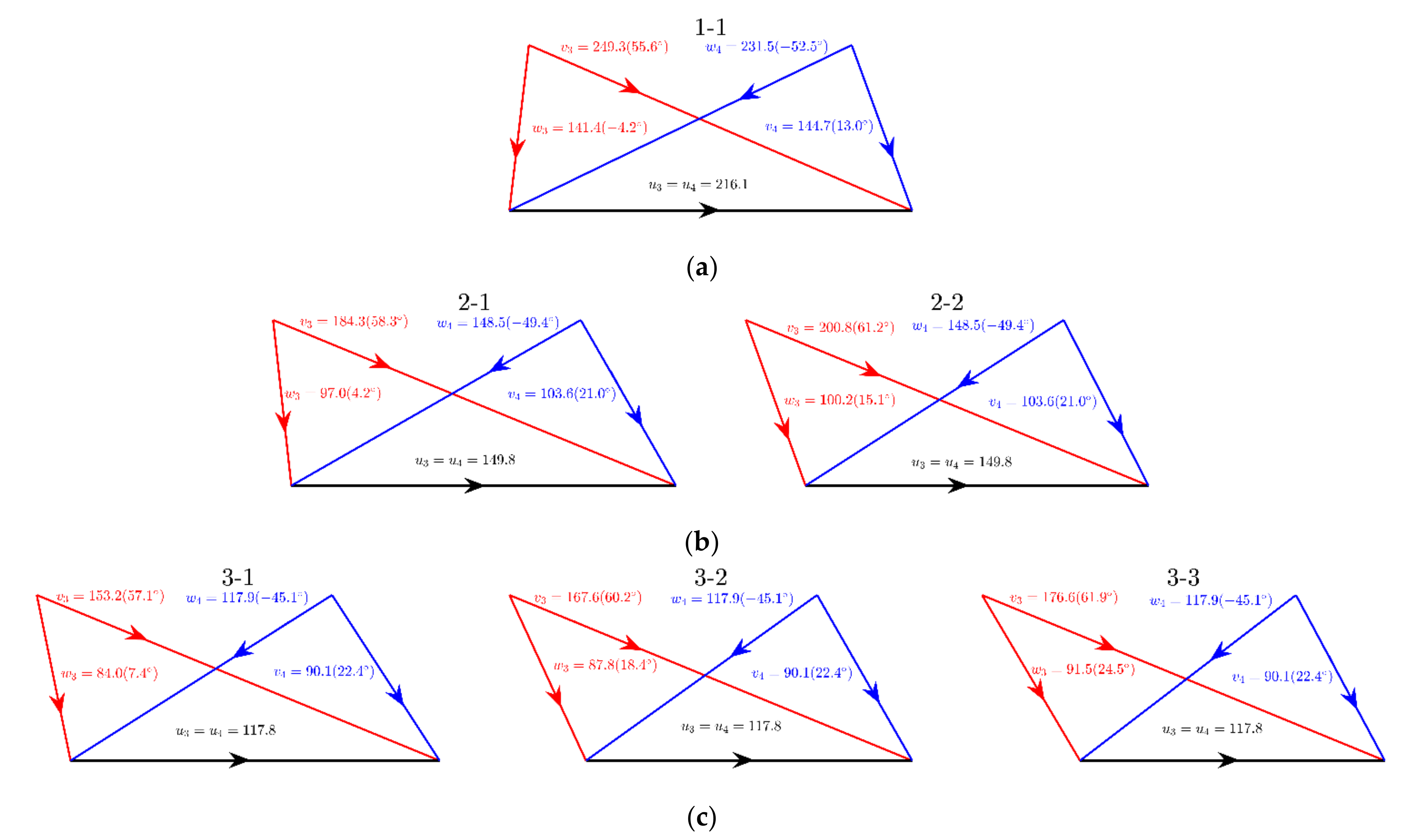
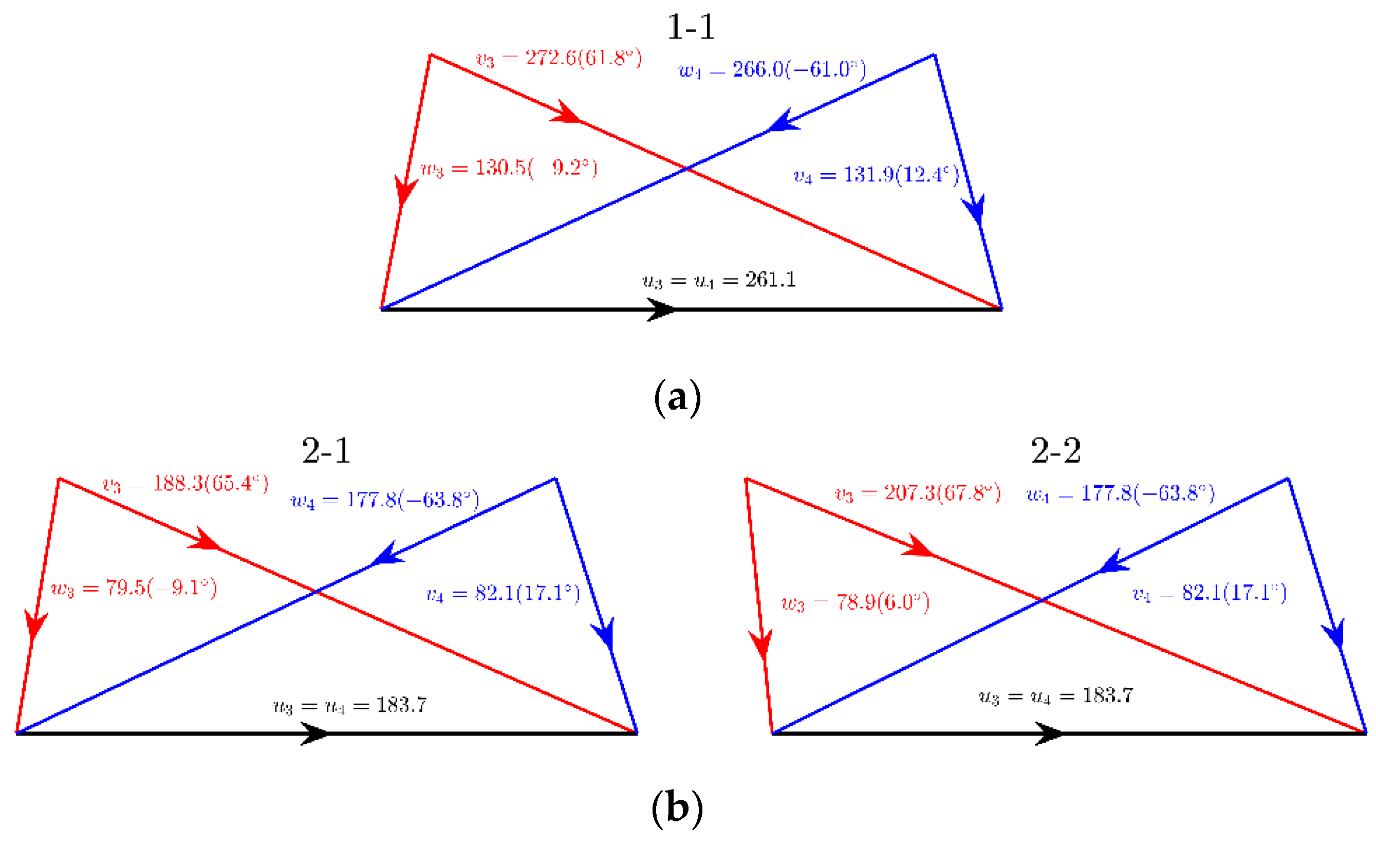
During the optimization process of the preliminary design, the velocity triangles and aerodynamic parameters at the inlet and outlet of each turbine stage are firstly determined according to the three dimensionless variables (load coefficient, flow coefficient, and reaction degree). The velocity triangles at the outlet of each rotor blade of a multi-stage turbine are calculated based on the repeated stage assumption. The results are shown in Figure 2 and Figure 3 for the two different values of the trailing edge thickness and tip clearance. In these figures, a in the symbol a-b represents the total turbine stages, and b represents the bth stage. With the increase of total turbine stages, the pressure ratio of a single stage decreases, and the flow velocity descends. For example, the circumferential velocities of the single-stage, two-stage, and three-stage turbines are 216.1 m/s, 149.8 m/s, and 117.8 m/s, respectively, showing a gradual reduction trend. When the trailing edge thickness and tip clearance are reduced to 0.1 mm, although the circumferential velocity, the absolute velocity at the rotor blade inlet, and the relative velocity at the rotor blade outlet increase, the relative velocity at the rotor blade inlet and exhaust velocity decrease, as shown in Figure 3. Taking the two-stage turbine as an example, when the trailing edge thickness and tip clearance are large, the circumferential velocity, absolute velocity at the inlet and relative velocity at the outlet of the first-stage rotor blade are 149.8 m/s, 184.3 m/s, and 148.5 m/s. When the trailing edge thickness and tip clearance decrease, the above values are 183.7 m/s, 188.3 m/s, and 177.8 m/s, respectively. With large values of the trailing edge thickness and tip clearance, the relative velocity at the rotor blade inlet and exhaust velocity of the two-stage turbine are 97.0 m/s and 103.6 m/s. These values are significantly reduced to 79.5 m/s and 82.1 m/s when the trailing edge thickness and tip clearance are reduced to 0.1 mm. It is indicated that reducing trailing edge thickness and tip clearance can effectively improve the conversion efficiency of kinetic energy to mechanical energy.
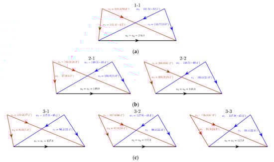
Figure 2.
Results of the velocity triangle at the inlet and outlet of rotor blade with a trailing edge thickness of 1 mm and a tip clearance of 0.35 mm: (a) single-stage turbine; (b) two-stage turbine; (c) three-stage turbine (red color represents the inlet and blue color denotes the outlet).
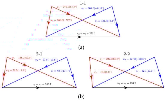
Figure 3.
Results of the velocity triangle at the inlet and outlet of rotor blade with a trailing edge thickness of 0.1 mm and a tip clearance of 0.1 mm: (a) single-stage turbine; (b) two-stage turbine; (c) three-stage turbine (red color represents the inlet and blue color denotes the outlet).
3.2. Geometric Parameters
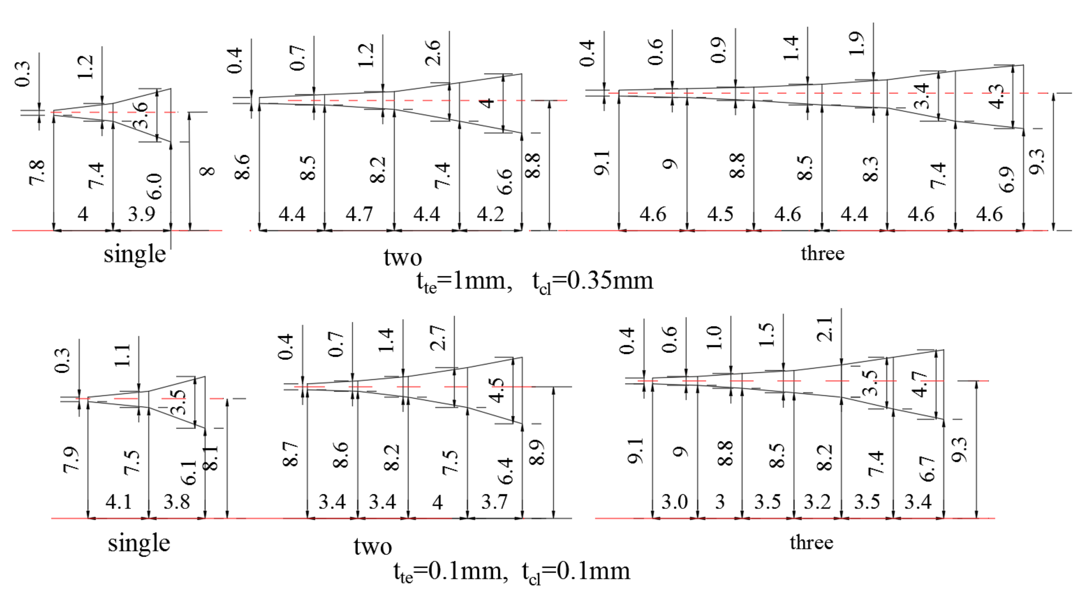
After the velocity triangles of the turbine stage are determined, the aerodynamic parameters of each section can be calculated, and then the geometric parameters of the turbine can be obtained according to the blade number and the hub-to-tip ratio. The diagrams of the meridional flow surface of the turbines are shown in Figure 4. The average radius of the turbine is between 7.8 and 9.3 mm, the height of the turbine blade is between 0.3 and 4.7 mm, and the turbine inlet height is very small as only 0.3–0.4 mm. This is because the mass flow rate at the design point is very small, only 0.3315 kg/s, while the pressure at the turbine inlet is as high as 6 MPa, leading to a small average radius of the turbine and a low height of the turbine inlet blade.
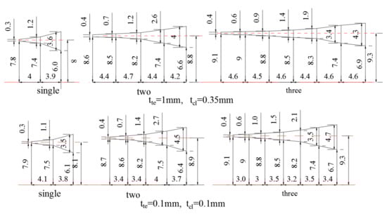
Figure 4.
Schematic of the meridional flow surface (unit: mm).
With the increase of stages, the heights at the outlet of the first rotor blade row decrease rapidly. For the large values of the trailing edge thickness and tip clearance, the geometric averages of the inlet and outlet rotor blade heights for the single-stage, two-stage, and three-stage turbines are 2.4 mm, 0.95 mm, and 0.75 mm, respectively. This is because the pressure ratio of each stage decreases with the increase of turbine stages, the outlet pressure of the first rotor blade increases, and the working fluid density rises, leading to the decrement of blade height. In addition, the average radius gradually increases with the increment of the number of turbine stages, and the outlet blade height of the final rotor blade also gradually enlarges. If the trailing edge thickness and tip clearance are reduced to 0.1 mm, the corresponding mean diameters of multi-stage turbines are basically unchanged, but the axial length becomes smaller. For instance, the axial lengths of the two-stage and three-stage turbines are reduced from 17.7 mm and 27.3 mm to 14.5 mm and 19.3 mm, respectively, indicating that the multi-stage turbines have a more compact volume after decreasing the trailing edge thickness and tip clearance.
In this study, to explore the efficiency improvement potential of small-scale axial turbine, a minimum tip clearance of 0.1 mm and a trailing edge thickness of 0.1 mm are assumed theoretically. Such a small clearance has been discussed in previous literatures. For instance, the minimum tip clearance was set as 0.1 mm in Casati et al. [39], 0.2 mm in Macchi et al. [51], 0.24 mm in Meroni et al. [25] based on a preliminary design. The manufacturing of axial turbine with such a small tip clearance is beyond the scope of this study. However, Enogia demonstrated a prototype of a 1 kW axial-flow turbine in ORC 2019 Conference whose clearance is very small. In this investigation, the turbine performance is predicted based on a conventional empirical mean-line model. The accuracy of the model for such a small axial turbine needs to be validated in the future.
Table 2 gives the results of cascade geometry parameters along the meridional plane under different thickness of the trailing edge and tip clearance. The ratio of the trailing edge thickness and the throat width has a great effect on the mixing process at the downstream of the trailing edge, and this ratio decreases as the turbine stages increase. When the trailing edge thickness and tip clearance are large, the ratio of the stator for the single-stage turbine is 0.49, and it reduces to 0.37 and 0.33 for two-stage and three-stage turbines, respectively. This is mainly due to the reduction of blade height. The ratio of tip clearance to blade height is an important factor affecting the clearance loss. With the increase of turbine stages, the ratio for the first rotor blade row ascends rapidly. For example, when the trailing edge thickness and tip clearance are large, the ratio of single-stage turbines is 0.07, while this ratios for the two-stage and three-stage turbines are 0.18 and 0.24, which are 2.6 and 3.4 times of the single-stage turbine. This is also caused by the reduction in blade height of this stage. As the trailing edge thickness and the tip clearance decrease, the ratio the blade tip clearance to the blade height drops, the same trend occurs for the ratio of the trailing edge thickness to the throat width. When the trailing edge thickness and tip clearance are large, these two ratios are 0.45 and 0.07, respectively. For the smaller values of the trailing edge thickness and tip clearance, they are reduced to 0.07 and 0.02, respectively, only 15.6% and 28.6% of the former results.
Table 2.
Results of the geometric parameters under different values of the trailing edge thickness and tip clearance.
The inlet and outlet Mach numbers of the blade rows are another important factor affecting the pressure loss coefficient. The inlet and outlet Mach numbers of the blade rows decrease with the increase of turbine stages, which is consistent with the variation trend of the flow velocity described in the previous section. The Mach number of the single-stage turbine is the highest and reaches 1.41. A slight supersonic speed appears at the outlet of stator blade row of the two-stage turbine with a maximum Mach number of 1.12. The flow velocity in the three-stage turbine is subsonic. Similar with the results of the flow velocity, when the trailing edge thickness and tip clearance descends, the Mach number at the inlet of the rotor blade decreases, while the Mach number at the outlet increases.
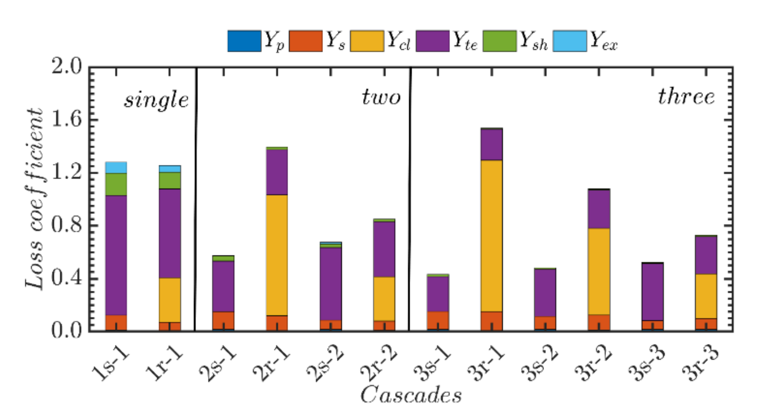
3.3. Pressure Loss
After the aerodynamic and geometric parameters of the cascades are obtained, the pressure loss coefficient can be further estimated for each turbine. The results of the total pressure loss coefficients for the turbines with large trailing edge thickness and tip clearance are shown in Figure 5. It can be seen that the trailing edge loss and the clearance loss are the main parts. This is because the geometric parameters related to these two losses (i.e., the ratio of trailing edge thickness to throat width and the ratio of tip clearance to blade height) are large. With the increase of turbine stages, the trailing edge loss of the cascade decreases. For single-stage turbine, the trailing edge loss of the first stator blade is 0.905; for the two-stage and three-stage turbines, the trailing edge losses are 0.383 and 0.263, reducing by 57.7% and 70.9%, respectively. However, the clearance loss of the first rotor blade increases sharply with the increase of turbine stages. The loss is 0.337 for the single-stage turbine, 0.916 for the two-stage turbine, and 1.146 for the three-stage turbine, which is increased by 2.7 and 3.4 times compared with the single-stage turbine. In addition, with the increase of turbine stages, the loss related to supersonic velocity decreases. For the single-stage turbine, the loss is 0.428, and for the two-stage and three-stage turbines, they are 0.125 and 0.060. This is because the pressure ratio of a single stage decreases as the turbine stage number increases, the blade height and velocity decline. Accordingly, the throat width increases, and the ratio of tip clearance to blade height increases, the ratio of trailing edge thickness to throat width decreases, leading to a decrease of the Mach number.

Figure 5.
Results of the pressure losses under the design condition (tte = 1 mm, tcl = 0.35 mm).
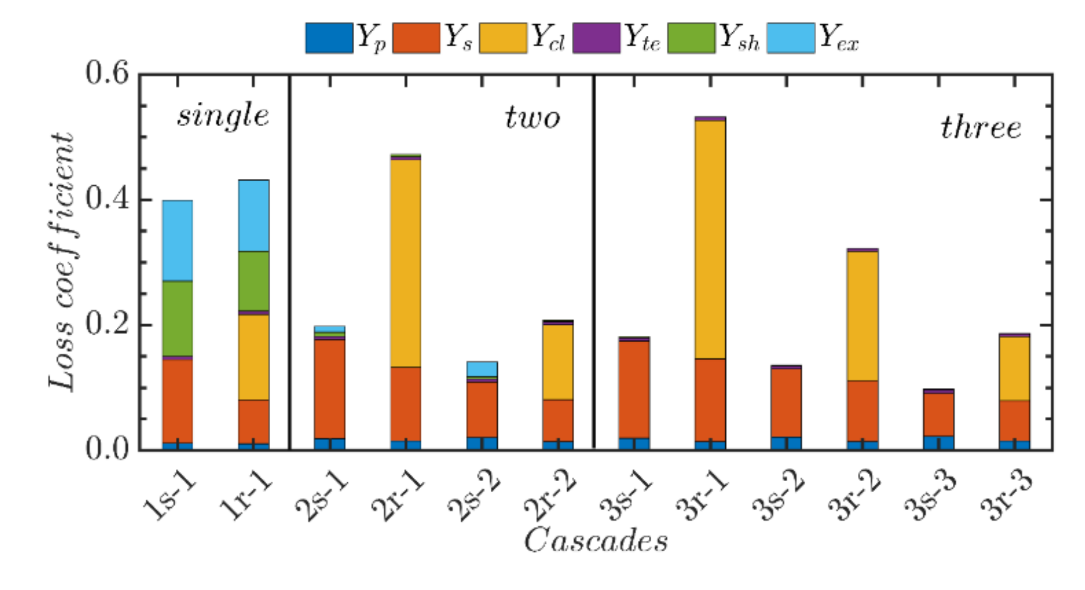
When the trailing edge thickness and tip clearance are reduced to 0.1 mm, the results of the pressure loss coefficient for the three turbines are shown in Figure 6. The total pressure loss coefficient of each cascade is greatly reduced, which is only 1/5–1/3 of that in the case of Figure 5. As the trailing edge thickness and tip clearance are reduced, the losses related to these two items decrease. The cascades of the stator and rotor of single-stage turbine are reduced by 0.9 and 0.869, respectively. Another obvious feature is that the proportion of supersonic related losses in the single-stage turbines is significantly higher than that in Figure 5. The proportions of these losses in the static and dynamic cascades are 62.3% and 48.5%, respectively, while they are 19.7% and 14.0% for large trailing edge thickness and tip clearance. This is mainly attributed to the small overall pressure loss coefficient after the reduction of these two dimensions. It is suggested that supersonic related losses should be paid more attention to under the condition of small trailing edge thickness and tip clearance, which can be effectively controlled by increasing turbine stages.

Figure 6.
Results of the pressure losses under the design condition (tte = 0.1 mm, tcl = 0.1 mm).
3.4. Turbine Performance
The overall performances of the three turbines are given in Table 3. Under the operation conditions with a high pressure ratio and a small mass flow rate, the turbine rotational speed of such a kW-class turbine using organic working fluid is very high. The rotational speed of the single-stage turbine is over 25,000 r/min, the speed of the two-stage turbine approaches to 20,000 r/min, and the speed of the three-stage turbine is close to 15,000 r/min. With the increase of turbine stages, the rotational speed decreases gradually. When the trailing edge thickness and tip clearance are large, the rotational speed of the three-stage turbine is less than half of that of the single-stage turbine. After the trailing edge thickness and tip clearance are reduced, the corresponding rotational speeds all increase. The more the turbine stages are, the smaller the rotational speed increase will be. In the case of large trailing edge thickness and tip clearance, turbine flow coefficient is larger, all above 0.65. In the case of small trailing edge thickness and tip clearance, the reactivity degrees decline to around 0.5. In general, the SP values of the turbines in the two cases are close to each other, in the range of 8–9 mm. With the increase of turbine stages, the dimensionless specific speed gradually decreases. Meanwhile, the corresponding specific speed of the turbines increases if the trailing edge thickness and tip clearance are reduced. The specific speed of different stages of the three turbines ranges from 0.39 to 1.03, all within the applicable range of axial-flow turbines, but the efficiency is lower than the predicted value of similarity theory [9], and this will cause discrepancies in the prediction of turbine efficiency using a map based on the specific speed and specific diameter for turbines with organic working fluid [54]. With the increase of turbine stages, the specific diameter gradually increases. If the trailing edge thickness and tip clearance decrease, a slight increase in the specific diameter occurs.
Table 3.
Comparison of axial-flow turbine performance under the design condition.
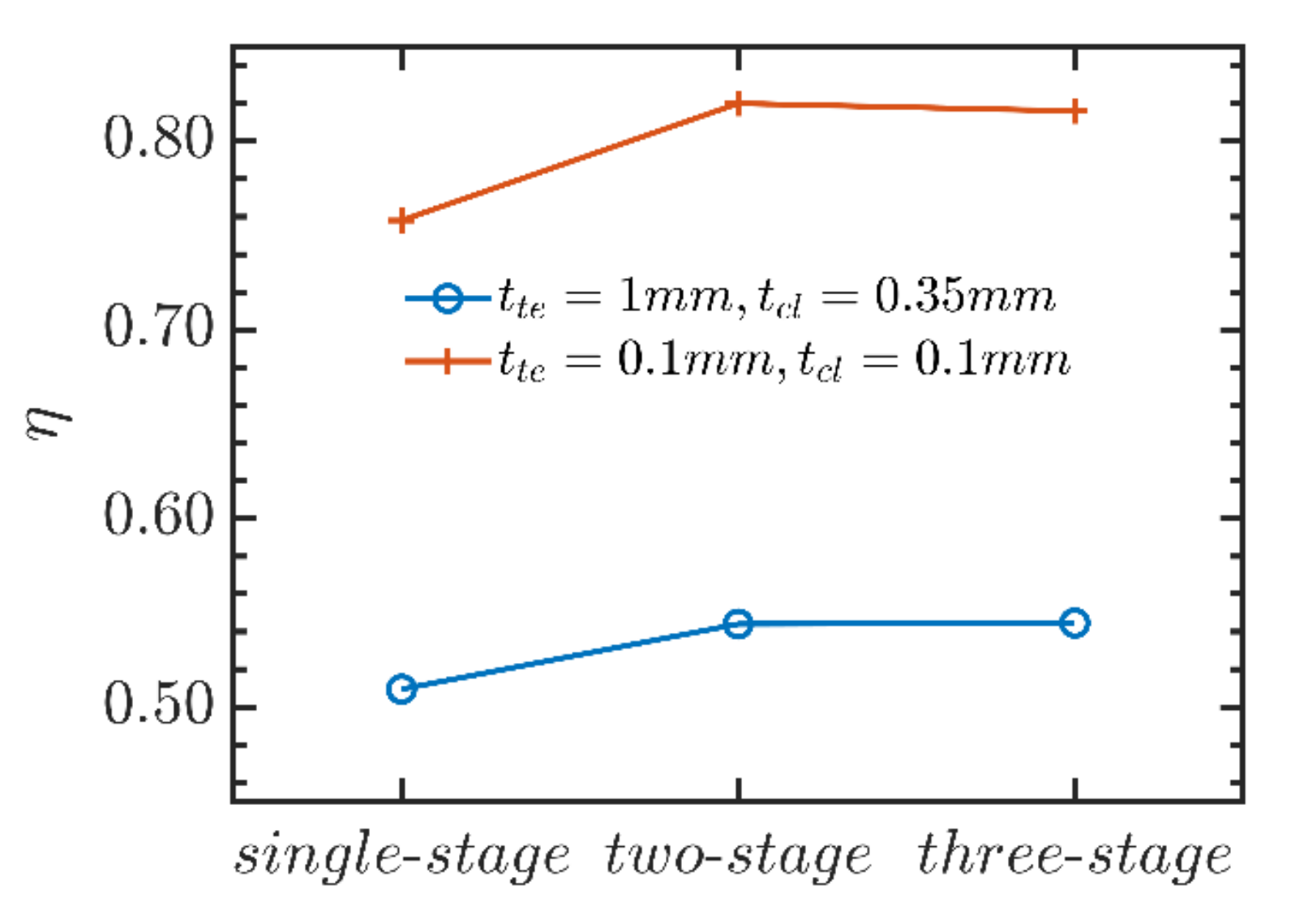
The variation of turbine efficiency with the turbine stages is shown in Figure 7. The single-stage turbine has the lowest efficiency, while the two-stage turbine has the largest efficiency, which is improved evidently compared with the single-stage turbine. The efficiency of the three-stage turbine is slightly lower than the two-stage turbine. When the number of stages of the axial-flow turbine increases from 1 to 2, the trailing edge loss and supersonic related loss reduce, which plays a leading role, making the turbine efficiency increases. However, if it continues to increase the number of stages to 3, the clearance loss of the first rotor blade increases, weakened the previous positive effects. Therefore, the turbine efficiency remains almost unchanged. When the trailing edge thickness and tip clearance are large, the turbine efficiencies are all lower, less than 55%. When the trailing edge thickness and tip clearance are reduced to 0.1 mm, the efficiency of each turbine is greatly improved, which arrives the peak as 82% for the two-stage turbine. As a result, the turbine output power can be significantly increased form less than 13 kW to about 19 kW by reducing trailing edge thickness and tip clearance.
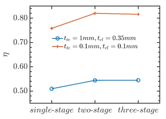
Figure 7.
Results of the turbine efficiency for the three axial-flow turbines.
The specific speed and specific diameter both increase when the trailing edge thickness and tip clearance are reduced, as shown in Table 3. The geometric dimension parameter SP is slightly reduced, indicating that the turbine is more compact, which is consistent with the results in the previous section. The results for the turbine efficiency, output power, and rotational speed of each turbine all are increased. For the two-stage turbine, these three parameters are increased by 50.7%, 49.2%, and 21%, respectively. As the trailing edge thickness and tip clearance reduce, the total pressure loss coefficient of the turbine cascade is greatly decreased, thus the turbine efficiency and output power are improved. However, the average diameters of the turbine are almost constant. According to the Euler equation of turbomachinery, the turbine rotational speed will increase. When the trailing edge thickness and tip clearance are reduced to 0.1 mm, the performance of the two-stage turbine is the best, and the output power and efficiency are 19.17 kW and 82%, respectively.
Normally, an impulse type turbine is more suitable in the case of a turbine with such a high specific power considering the axial thrust force although a high Ma number and large shock loss occur in the injector. In addition, a multi-stage pressure-compounded impulse type axial turbine [55] can be used to reduce the rotation speed and Ma number. However, the design and performance analysis of impulse type turbine for supercritical ORC applications are beyond the scope of this study.
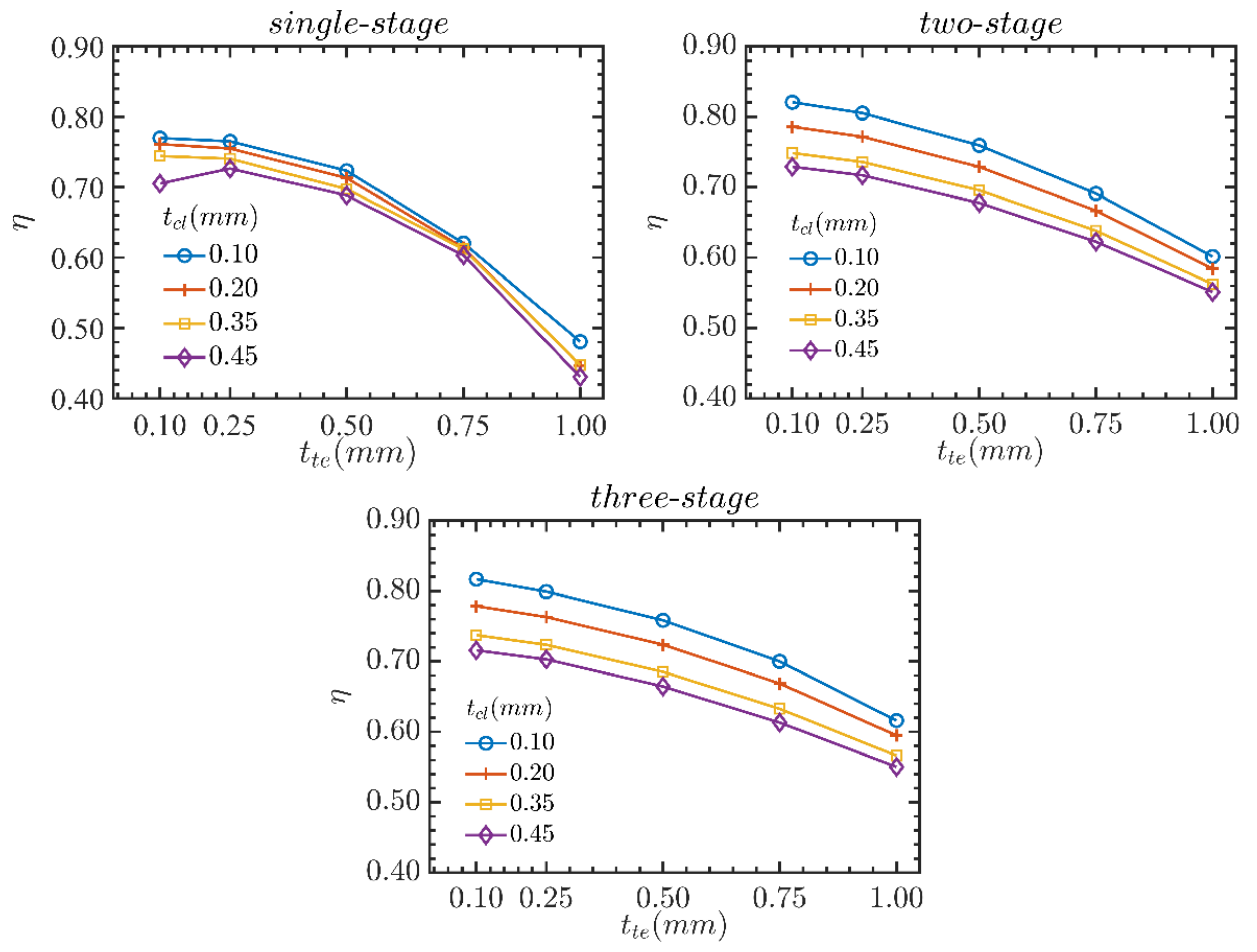
3.5. Effects of Trailing Edge Thickness
In order to quantify the influences of trailing edge thickness and tip clearance on the turbine performance, the results for the three turbines are determined as the trailing edge thickness ranges from 0.1 to 1 mm and the tip clearance increases from 0.1 to 0.45 mm. Figure 8 shows the outcomes of the single-stage, two-stage, and three-stage turbines. It can be seen that the turbine efficiency increases with the decrease of tip clearance and trailing edge thickness. When they reach the minimum value of 0.1 mm simultaneously, the efficiencies of the three turbines reach the highest. Meanwhile, the variation of trailing edge thickness has a great influence on the single-stage turbine, while the influence of tip clearance on the performance of single-stage turbine is weak. For two-stage and three-stage turbines, both the trailing edge thickness and tip clearance have great effects on the efficiency.
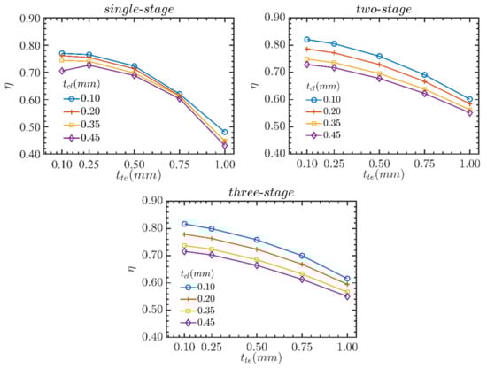
Figure 8.
Effects of trailing edge thickness and tip clearance on turbine efficiency.
4. Performance under Off-Design Conditions
In practical applications, the variation of heat source conditions and the power output fluctuation will lead to the ORC system operating in the off-design condition. Accordingly, the turbine may deviate from the design point and operate in the off-design conditions. Therefore, ensuring a high turbine performance in off-design conditions is important for efficiency improvement of the system. Based on the designed geometric parameters of the turbines, the performances of the three axial-flow turbines under off-design conditions are further analyzed. The off-design conditions are defined by assuming that the total temperature and pressure at the turbine inlet and the rotational speed vary within a certain range. The static pressure at the turbine outlet is kept the same as the design condition. For the single-stage turbine, p0,in/p0,in,d ranges from 0.6 to 1.4. For the multi-stage turbines, p0,in/p0,in,d ranges from 0.6 to 1.6 and T0,in − T0,in,d is in the interval between −20 K and 20 K. The range of rotational speed N/Nd is set from 0.6 to 1.2. This section first analyzes the performance characteristics under the off-design conditions in the case of small trailing edge thickness and tip clearance. Then they are compared with the case of large trailing edge thickness and tip clearance to evaluate the influence on the performance of the multi-stage turbines.
4.1. Performance Characteristics
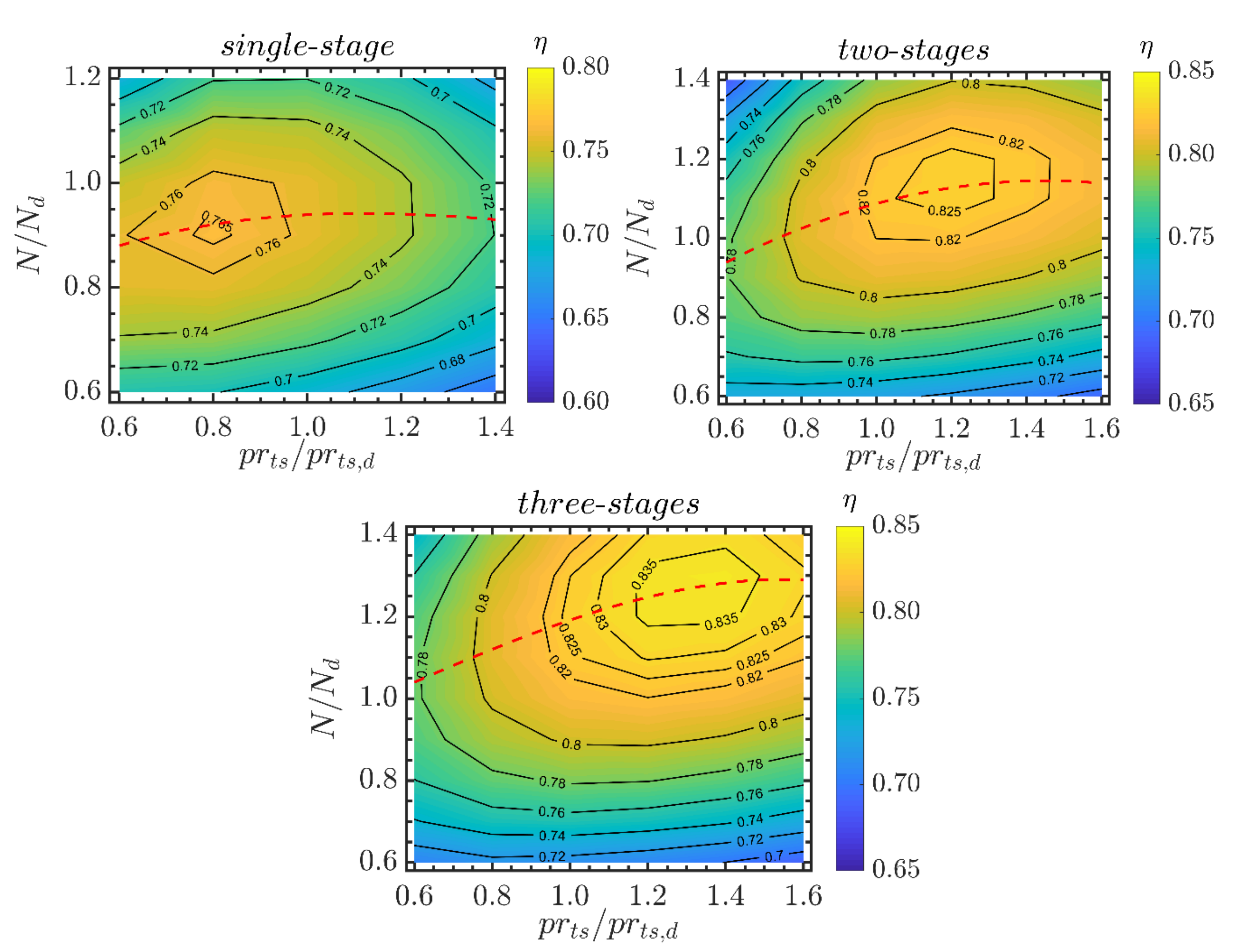
Figure 9 shows the maps of the turbine efficiencies for the three axial-flow turbines based on the normalized pressure ratio and the normalized rotational speed when the trailing edge thickness and tip clearance are both 0.1 mm. The maximum efficiency of the single-stage turbine is 0.767, and the corresponding normalized pressure ratio and speed are 0.8 and 0.9, respectively. The maximum efficiency of the two-stage and three-stage turbines are 0.828 (prts/prts,d = 1.2, N/Nd = 1.1) and 0.838 (prts/prts,d = 1.3, N/Nd = 1.3). The peak turbine efficiency and the corresponding normalized pressure ratio and rotational speed all increase with the increase of turbine stages, indicating that the multi-stage turbine operates under the off-design condition with a higher pressure ratio and rotational speed can improve the efficiency, while the single-stage turbine is more suitable for the off-design region with a slightly lower pressure ratio and rotational speed. In the region far away from the peak efficiency zone, the turbine efficiency will be decreased evidently. The variation magnitude of the efficiency for the single-stage turbine is small over the entire operation scope, while the efficiencies of two-stage and three-stage turbines decrease apparently under the off-design zones far from the peak point. The red dotted line in the figure is the optimal operation line (OOL) which labels the maximum efficiency trajectory under normalized pressure ratios. With the increase of normalized pressure ratio, the corresponding efficiency and normalized speed along the OOL first increased and then decreased for the three turbines. The variation range of the single-stage turbine is small, while the variations of the multi-stage turbines are larger.

Figure 9.
Maps of the turbine efficiency when the total temperature at the turbine inlet is 300 °C (tte = 0.1 mm, tcl = 0.1 mm).
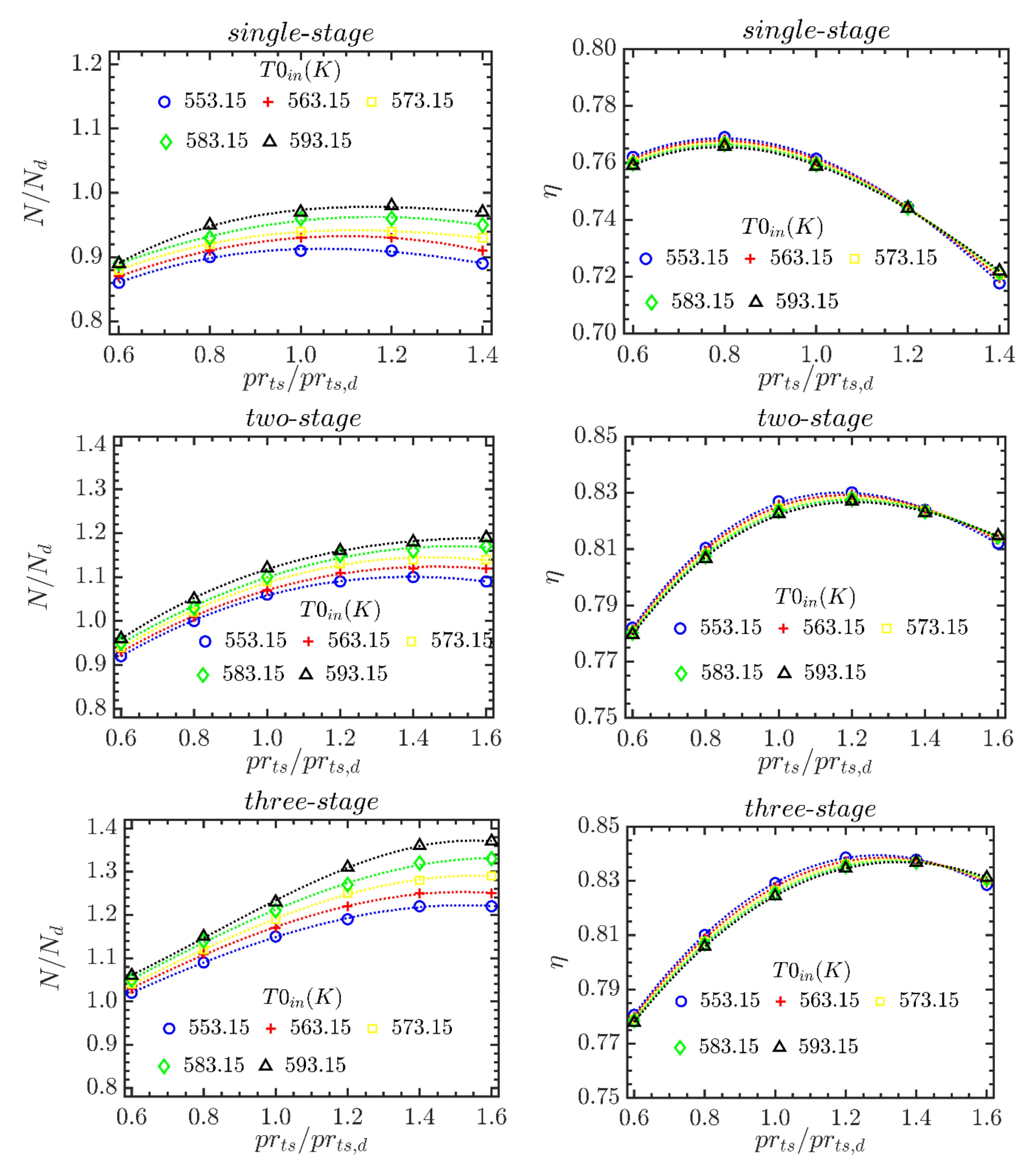
The results of the OOL for the three turbines under different turbine inlet temperatures, are shown in Figure 10. The effect of turbine inlet temperature on the turbine efficiency is small. On the other hand, with the increase of the temperature, the corresponding normalized speed gradually increases, and the variation magnitude rises with the increase of the normalized pressure ratio. For example, for the three-stage turbine, the increments are 0.04 and 0.15 when the normalized pressure ratio is 0.6 and 1.6, respectively, and the latter is 3.75 times as much as the former. This indicates that the total temperature at the turbine inlet has an evident influence on the optimal normalized speed, and the influence becomes stronger with the increase of the normalized pressure ratio. Therefore, the rotational speed needs to be adjusted according to the turbine inlet temperature. When the normalized pressure ratios are the same, a higher normalized speed is achieved for the turbine with more stages. The variation range of the speed is also larger, meaning a stronger demand of turbine speed regulation under the off-design operation process. There is a corresponding pressure ratio for each turbine, which makes the turbine efficiency the highest. Moreover, this pressure ratio shifts to the right direction for the turbine with higher stages.
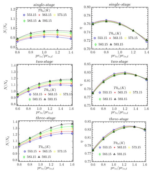
Figure 10.
Results of the normalized speed and efficiency for the three axial-flow turbine under different turbine inlet temperatures (tte = 0.1 mm, tcl = 0.1 mm).
For the multi-stage turbines, when the pressure ratio is lower than that corresponding to the highest efficiency, because the rotational speed decreases, the relative angle at the rotor blade inlet increases, leading to an increase in flow deflection angle and strengthening secondary flows. Therefore, the secondary flow loss and clearance loss increase, especially the clearance loss at the first rotor blade row ascends greatly, showing that the clearance loss of the first stage is the highest. It is indicated that the clearance loss is the most important factor for the off-design performance of the two-stage and three-stage turbines. For the single-stage turbine, when the pressure ratio is greater than the optimal pressure ratio, the exit velocity of the final stage increases dramatically, resulting in an increase of the leaving velocity loss and a reduction of turbine efficiency. In this case, the single-stage turbine has limited expansion capacity and is not suitable for off-design conditions with a high pressure ratio.
4.2. Effects of Trailing Edge Thickness
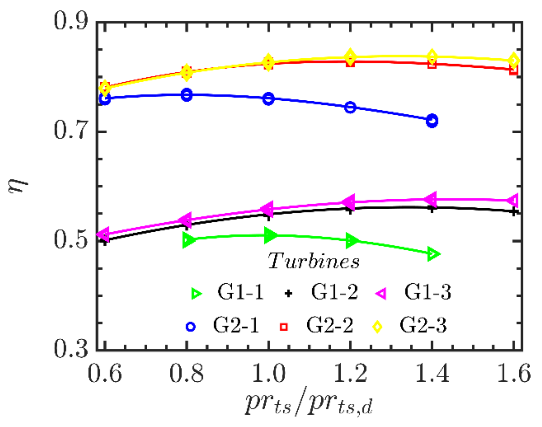
Figure 11 shows a comparison of the efficiency along the OOL for the turbines. The efficiency of the single-stage turbine is lower than those of the multi-stage turbines. As the normalized pressure ratio increases, the declining magnitude enlarges. A minimum difference of 0.016 of the efficiency between the two-stage and single-stage turbines is obtained while this difference increases to 0.1 when the normalized pressure ratio is 1.4. The discrepancy between the two-stage and three-stage turbines is very small. Therefore, a multi-stage turbine is more suitable than single-stage turbine for ORC systems with a high pressure ratio and a small mass flow rate due to a higher efficiency and a lower rotational speed.
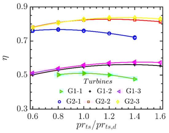
Figure 11.
Results of turbine efficiency along the OOL vs. normalized pressure ratio.
In Figure 11, the results for the two values of the trailing edge thickness and tip clearance are displayed. G1-i refers to the results with trailing edge thickness of 1 mm and tip clearance of 0.35 mm, and G2-i refers to the turbines when the trailing edge thickness and tip clearance both are 0.1 mm, where i represents the number of stages (i = 1,2,3). Trailing edge thickness and tip clearance have a significant influence on the efficiency of the OOL curve under off-design conditions. Under the entire off-design conditions, the turbine efficiency with small trailing edge thickness and tip clearance is significantly higher than that with conventional dimensions. For instance, the efficiency along the OOL ranges from 0.781 to 0.828 for the two-stage turbines with small trailing edge thickness and tip clearance, which is 0.26 to 0.28 higher than the two-stage turbine with a larger trailing edge thickness and tip clearance. Therefore, the reduction of trailing edge thickness and clearance is beneficial to the improvement of turbine efficiency under off-design conditions.
5. Conclusions
Aiming at efficiency improvement of a small-scale ORC with high pressure ratio and small mass flow rate, the performance of a kW-class axial-flow turbine is studied. First, the preliminary designs of the single-stage, two-stage, and three-stage turbines are completed, and the geometric parameters are obtained. Then, the influences of the number of stages, trailing edge thickness, and tip clearance on the velocity triangle, aerodynamic, and geometric parameters, total pressure loss, and overall turbine performance are analyzed at the design condition. Finally, the turbine performance under off-design conditions is discussed. The main conclusions are as follows:
- As the number of stages increases, the height of first rotor blade row drops, causing an apparent increase of the pressure losses of the first rotor. As a result, the total pressure loss decreases and the turbine efficiency increases significantly for the two-stage turbine compared with the single-stage one. When the stage number continues to increase to three, the reduction of total pressure loss and improvement of turbine efficiency are very small. However, the turbine speed decreases significantly.
- Under the design condition, the inlet velocity of the rotor blade increases, but the leaving velocity decreases, and the turbine geometry becomes more compact. When the clearance and trailing edge reach 0.1 mm, the efficiencies of the single-stage, two-stage, and three-stage turbines are 75.8%, 82%, and 81.6%, respectively. The corresponding output powers are 18.34 kW, 19.17 kW, and 19.00 kW. However, it also increases the turbine rotational speed. The output power and efficiency of the two-stage turbine are significantly greater than that of the single-stage turbine. Meanwhile, the single-stage and two-stage turbines operate at more than 190,000 r/min and may encounter difficulties in the manufacturing process. The performance of the three-stage turbine is similar to that of the two-stage turbine, but the rotational speed drops to 150,000 r/min, which is more plausible in practical production.
- Under off-design conditions, the efficiency of the two-stage turbine is apparently greater than that of the single-stage one, while the efficiency difference between the three-stage and two-stage turbines is very small. The variation magnitudes of the efficiency under the off-design conditions for the two-stage and three-stage turbines are larger than that of the single-stage turbine. When the trailing edge thickness and tip clearance are reduced to 0.1 mm, the turbine efficiency can also be significantly enhanced under off-design conditions.
Author Contributions
Conceptualization, E.W. and N.P.; methodology, N.P.; software, N.P.; validation, N.P. and E.W.; formal analysis, N.P.; investigation, N.P.; resources, E.W.; data curation, N.P.; writing—original draft preparation, N.P.; writing—review and editing, E.W. and H.Z.; visualization, N.P.; supervision, E.W.; project administration, E.W.; funding acquisition, E.W. All authors have read and agreed to the published version of the manuscript.
Funding
This research was funded by National Natural Science Foundation of China, grant number 51876009.
Institutional Review Board Statement
Not applicable.
Informed Consent Statement
Not applicable.
Data Availability Statement
No new data were created or analyzed in this study. Data sharing is not applicable to this article.
Conflicts of Interest
The authors declare no conflict of interest.
Nomenclature
| A | area (m2) |
| h | enthalpy (kJ/kg) |
| m | mass flow rate (kg/s) |
| Ma | Mach number (-) |
| n | stages (-) |
| p | pressure (kPa) |
| pr | pressure ratio (-) |
| r | radius (mm) |
| R | degree of reaction (-) |
| s | entropy (J/(kgK)) |
| SP | size parameter (mm) |
| T | temperature (K) |
| t | blade clearance, trailing edge (mm) |
| u | peripheral velocity (m/s) |
| v | velocity (m/s) |
| w | relative velocity (m/s) |
| Y | total pressure loss coefficient (-) |
| z | blade numbers (-) |
| α | flow angle (°) |
| η | isentropic efficiency (-) |
| λ | radial ratio between the hub and tip (-) |
| Φ | flow coefficient (-) |
| Ψ | loading coefficient (-) |
Subscripts
| 0 | total |
| 1 | stator inlet |
| 2 | stator outlet |
| 3 | rotor inlet |
| 4 | rotor outlet |
| cl | blade clearance loss |
| d | design point |
| ex | supersonic expansion loss |
| h | hub |
| in | inlet |
| m | mean radius |
| out | outlet |
| p | profile loss |
| rel | relative |
| s | isentropic, secondary loss |
| sh | shock loss |
| stage | turbine stage |
| t | tip |
| te | blade trailing edge loss |
| ts | total to static |
| turb | turbine |
| tt | total to total |
| x | axial direction |
References
- Haghighi, A.; Pakatchian, M.R.; Assad, M.E.; Duy, V.N.; Nazari, M.A. A review on geothermal Organic Rankine cycles: Modeling and optimization. J. Therm. Anal. Calorim. 2021, 144, 1799–1814. [Google Scholar] [CrossRef]
- Ahmadi, A.; Assad, M.E.; Jamali, D.H.; Kumar, R.; Li, Z.X.; Salameh, T.; Al-Shabi, M.; Ehyae, M.A. Applications of geothermal organic Rankine Cycle for electricity production. J. Clean Prod. 2020, 274, 20. [Google Scholar] [CrossRef]
- Kasaeian, A.; Bellos, E.; Shamaeizadeh, A.; Tzivanidis, C. Solar-driven polygeneration systems: Recent progress and outlook. Appl. Energy 2020, 264, 32. [Google Scholar] [CrossRef]
- Mahlia, T.M.I.; Syaheed, H.; Abas, A.E.P.; Kusumo, F.; Shamsuddin, A.H.; Ong, H.C.; Bilad, M.R. Organic Rankine Cycle (ORC) System Applications for Solar Energy: Recent Technological Advances. Energies 2019, 12, 2930. [Google Scholar] [CrossRef] [Green Version]
- Loni, R.; Najafi, G.; Bellos, E.; Rajaee, F.; Said, Z.; Mazlan, M. A review of industrial waste heat recovery system for power generation with Organic Rankine Cycle: Recent challenges and future outlook. J. Clean Prod. 2021, 287, 28. [Google Scholar] [CrossRef]
- Zhu, S.P.; Zhang, K.; Deng, K.Y. A review of waste heat recovery from the marine engine with highly efficient bottoming power cycles. Renew. Sust. Energ. Rev. 2020, 120, 17. [Google Scholar] [CrossRef]
- Xu, B.; Rathod, D.; Yebi, A.; Filipi, Z.; Onori, S.; Hoffman, M. A comprehensive review of organic rankine cycle waste heat recovery systems in heavy-duty diesel engine applications. Renew. Sust. Energ. Rev. 2019, 107, 145–170. [Google Scholar] [CrossRef]
- Shi, L.F.; Shu, G.Q.; Tian, H.; Deng, S. A review of modified Organic Rankine cycles (ORCs) for internal combustion engine waste heat recovery (ICE-WHR). Renew. Sust. Energ. Rev. 2018, 92, 95–110. [Google Scholar] [CrossRef]
- Balje, O.E. Turbomachines: A Guide to Design, Selection and Theory; John Wiley & Sons: New York, NY, USA, 1981. [Google Scholar]
- Hu, D.S.; Zheng, Y.; Wu, Y.; Li, S.L.; Dai, Y.P. Off-design performance comparison of an organic Rankine cycle under different control strategies. Appl. Energy 2015, 156, 268–279. [Google Scholar] [CrossRef]
- Liu, C.W.; Gao, T.Y. Off-design performance analysis of basic ORC, ORC using zeotropic mixtures and composition-adjustable ORC under optimal control strategy. Energy 2019, 171, 95–108. [Google Scholar] [CrossRef]
- Bahadormanesh, N.; Rahat, S.; Yarali, M. Constrained multi-objective optimization of radial expanders in organic Rankine cycles by firefly algorithm. Energy Conv. Manag. 2017, 148, 1179–1193. [Google Scholar] [CrossRef]
- Giovannelli, A.; Archilei, E.M.; Salvini, C. Two-Stage Radial Turbine for a Small Waste Heat Recovery Organic Rankine Cycle (ORC) Plant. Energies 2020, 13, 1054. [Google Scholar] [CrossRef] [Green Version]
- Alshammari, F.; Karvountzis-Kontakiotis, A.; Pesyridis, A.; Alatawi, I. Design and study of back-swept high pressure ratio radial turbo-expander in automotive organic Rankine cycles. Appl. Therm. Eng. 2020, 164, 114549. [Google Scholar] [CrossRef]
- Erbas, M.; Biyikoglu, A. Design and multi-objective optimization of organic Rankine turbine. Int. J. Hydrogen Energy 2015, 40, 15343–15351. [Google Scholar] [CrossRef]
- Fiaschi, D.; Manfrida, G.; Maraschiello, F. Thermo-fluid dynamics preliminary design of turbo-expanders for ORC cycles. Appl. Energy 2012, 97, 601–608. [Google Scholar] [CrossRef]
- Kim, J.S.; Kim, D.Y. Preliminary Design and Off-Design Analysis of a Radial Outflow Turbine for Organic Rankine Cycles. Energies 2020, 13, 2118. [Google Scholar] [CrossRef]
- Dong, B.S.; Xu, G.Q.; Li, T.T.; Luo, X.; Quan, Y.K. Parametric analysis of organic Rankine cycle based on a radial turbine for low-grade waste heat recovery. Appl. Therm. Eng. 2017, 126, 470–479. [Google Scholar] [CrossRef]
- Pan, L.S.; Wang, H.X. Improved analysis of Organic Rankine Cycle based on radial flow turbine. Appl. Therm. Eng. 2013, 61, 606–615. [Google Scholar] [CrossRef] [Green Version]
- Song, J.; Gu, C.W.; Ren, X.D. Influence of the radial-inflow turbine efficiency prediction on the design and analysis of the Organic Rankine Cycle (ORC) system. Energy Conv. Manag. 2016, 123, 308–316. [Google Scholar] [CrossRef]
- Sauret, E.; Rowlands, A.S. Candidate radial-inflow turbines and high-density working fluids for geothermal power systems. Energy 2011, 36, 4460–4467. [Google Scholar] [CrossRef]
- Han, Z.H.; Mei, Z.K.; Li, P. Multi-objective optimization and sensitivity analysis of an organic Rankine cycle coupled with a one-dimensional radial-inflow turbine efficiency prediction model. Energy Conv. Manag. 2018, 166, 37–47. [Google Scholar] [CrossRef]
- Li, P.; Han, Z.H.; Jia, X.Q.; Mei, Z.K.; Han, X.; Wang, Z. Analysis and comparison on thermodynamic and economic performances of an organic Rankine cycle with constant and one-dimensional dynamic turbine efficiency. Energy Conv. Manag. 2019, 180, 665–679. [Google Scholar] [CrossRef]
- White, M.T.; Sayma, A.I. A Generalised Assessment of Working Fluids and Radial Turbines for Non-Recuperated Subcritical Organic Rankine Cycles. Energies 2018, 11, 800. [Google Scholar] [CrossRef] [Green Version]
- Meroni, A.; Seta, A.; Andreasen, J.G.; Pierobon, L.; Persico, G.; Haglind, F. Combined Turbine and Cycle Optimization for Organic Rankine Cycle Power SystemsPart A: Turbine Model. Energies 2016, 9, 313. [Google Scholar] [CrossRef] [Green Version]
- La Seta, A.; Meroni, A.; Andreasen, J.G.; Pierobon, L.; Persico, G.; Haglind, F. Combined Turbine and Cycle Optimization for Organic Rankine Cycle Power Systems-Part B: Application on a Case Study. Energies 2016, 9, 393. [Google Scholar] [CrossRef] [Green Version]
- Meroni, A.; Andreasen, J.G.; Persico, G.; Haglind, F. Optimization of organic Rankine cycle power systems considering multistage axial turbine design. Appl. Energy 2018, 209, 339–354. [Google Scholar] [CrossRef] [Green Version]
- Mikielewicz, J.; Piwowarski, M.; Kosowski, K. Design analysis of turbines for co-generating micro-power plant working in accordance with organic Rankine’s cycle. Pol. Marit. Res. 2009, 16, 34–38. [Google Scholar] [CrossRef]
- Morgese, G.; Fornarelli, F.; Oresta, P.; Capurso, T.; Stefanizzi, M.; Camporeale, S.M.; Torresi, M. Fast Design Procedure for Turboexpanders in Pressure Energy Recovery Applications. Energies 2020, 13, 3669. [Google Scholar] [CrossRef]
- Quan, Y.K.; Liu, J.Y.; Zhang, C.Z.; Wen, J.; Xu, G.Q.; Dong, B.S. Aerodynamic design of an axial impulse turbine for the high-temperature organic Rankine cycle. Appl. Therm. Eng. 2020, 167, 114708. [Google Scholar] [CrossRef]
- Witanowski, L.; Klonowicz, P.; Lampart, P.; Suchocki, T.; Jedrzejewski, L.; Zaniewski, D.; Klimaszewski, P. Optimization of an axial turbine for a small scale ORC waste heat recovery system. Energy 2020, 20, 118059. [Google Scholar] [CrossRef]
- Al Jubori, A.; Al-Dadah, R.K.; Mahmoud, S.; Ennil, A.S.B.; Rahbar, K. Three dimensional optimization of small-scale axial turbine for low temperature heat source driven organic Rankine cycle. Energy Conv. Manag. 2017, 133, 411–426. [Google Scholar] [CrossRef]
- Al Jubori, A.M.; Al-Dadah, R.; Mahmoud, S. An innovative small-scale two-stage axial turbine for low-temperature organic Rankine cycle. Energy Conv. Manag. 2017, 144, 18–33. [Google Scholar] [CrossRef]
- Al Jubori, A.M.; Al-Dadah, R.; Mahmoud, S. New performance maps for selecting suitable small-scale turbine configuration for low-power organic Rankine cycle applications. J. Clean Prod. 2017, 161, 931–946. [Google Scholar] [CrossRef] [Green Version]
- Al Jubori, A.M.; Al-Dadah, R.K.; Mahmoud, S.; Daabo, A. Modelling and parametric analysis of small-scale axial and radial outflow turbines for Organic Rankine Cycle applications. Appl. Energy 2017, 190, 981–996. [Google Scholar] [CrossRef] [Green Version]
- Weiss, A.P.; Popp, T.; Zinn, G.; Preissinger, M.; Bruggemann, D. A micro-turbine-generator-construction-kit (MTG-c-kit) for small-scale waste heat recovery ORC-Plants. Energy 2019, 181, 51–55. [Google Scholar] [CrossRef]
- Weiss, A.P.; Popp, T.; Muller, J.; Hauer, J.; Bruggemann, D.; Preissinger, M. Experimental characterization and comparison of an axial and a cantilever micro-turbine for small-scale Organic Rankine Cycle. Appl. Therm. Eng. 2018, 140, 235–244. [Google Scholar] [CrossRef]
- Bahamonde, S.; Pini, M.; De Servi, C.; Rubino, A.; Colonna, P. Method for the Preliminary Fluid Dynamic Design of High-Temperature Mini-Organic Rankine Cycle Turbines. J. Eng. Gas. Turbines Power-Trans. ASME 2017, 139, 082606. [Google Scholar] [CrossRef]
- Casati, E.; Vitale, S.; Pini, M.; Persico, G.; Colonna, P. Centrifugal Turbines for Mini-Organic Rankine Cycle Power Systems. J. Eng. Gas. Turbines Power-Trans. ASME 2014, 136, 122607. [Google Scholar] [CrossRef]
- Uusitalo, A.; Turunen-Saaresti, T.; Honkatukia, J.; Colonna, P.; Larjola, J. Siloxanes as Working Fluids for Mini-ORC Systems Based on High-Speed Turbogenerator Technology. J. Eng. Gas. Turbines Power-Trans. ASME 2013, 135, 042305. [Google Scholar] [CrossRef]
- De Servi, C.M.; Burigana, M.; Pini, M.; Colonna, P. Design Method and Performance Prediction for Radial-Inflow Turbines of High-Temperature Mini-Organic Rankine Cycle Power Systems. J. Eng. Gas. Turbines Power-Trans. ASME 2019, 141, 091021. [Google Scholar] [CrossRef] [Green Version]
- Capata, R.; Hernandez, G. Preliminary Design and Simulation of a Turbo Expander for Small Rated Power Organic Rankine Cycle (ORC). Energies 2014, 7, 7067–7093. [Google Scholar] [CrossRef] [Green Version]
- Flores, R.A.; Jimenez, H.M.A.; Gonzalez, E.P.; Uribe, L.A.G. Aerothermodynamic design of 10 kW radial inflow turbine for an organic flashing cycle using low-enthalpy resources. J. Clean Prod. 2020, 251, 119713. [Google Scholar] [CrossRef]
- Mounier, V.; Olmedo, L.E.; Schiffmann, J. Small scale radial inflow turbine performance and pre-design maps for Organic Rankine Cycles. Energy 2018, 143, 1072–1084. [Google Scholar] [CrossRef]
- Uusitalo, A.; Turunen-Saaresti, T.; Honkatukia, J.; Dhanasegaran, R. Experimental study of small scale and high expansion ratio ORC for recovering high temperature waste heat. Energy 2020, 208, 118321. [Google Scholar] [CrossRef]
- Alshammari, F.; Pesyridis, A.; Karvountzis-Kontakiotis, A.; Franchetti, B.; Pesmazoglou, Y. Experimental study of a small scale organic Rankine cycle waste heat recovery system for a heavy duty diesel engine with focus on the radial inflow turbine expander performance. Appl. Energy 2018, 215, 543–555. [Google Scholar] [CrossRef]
- Al Jubori, A.M.; Al-Mousawi, F.N.; Rahbar, K.; Al-Dadah, R.; Mahmoud, S. Design and manufacturing a small-scale radial-inflow turbine for clean organic Rankine power system. J. Clean Prod. 2020, 257, 120488. [Google Scholar] [CrossRef]
- Dixon, S.L.; Hall, C.A. Fluid Mechanics and Thermodynamics of Turbomachinery, 6th ed.; Elsevier: Amsterdam, The Netherlands, 2010. [Google Scholar]
- Peng, N.J.; Wang, E.H.; Meng, F.X. Off-design performance comparison of single-stage axial turbines using CO2 and zeotropic mixture for low-temperature heat source. Energy Conv. Manag. 2020, 213, 112838. [Google Scholar] [CrossRef]
- Aunger, R.H. Turbine Aerodynamics: Axial-Flow and Radial-Inflow Turbine Design and Analysis; The American Society of Mechanical Engineers: New York, NY, USA, 2006. [Google Scholar]
- Macchi, E.; Perdichizzi, A. Efficiency prediction for axial flow turbines operating with nonconventional fluids. Trans. ASME J. Eng. Power 1981, 103, 718–724. [Google Scholar] [CrossRef]
- Wang, E.; Yu, Z.; Zhang, H.; Yang, F. A regenerative supercritical-subcritical dual-loop organic Rankine cycle system for energy recovery from the waste heat of internal combustion engines. Appl. Energy 2017, 190, 574–590. [Google Scholar] [CrossRef]
- Lemmon, E.W.; Huber, M.L.; McLinden, M.O. NIST Standard Reference Database 23: Reference Fluid Thermodynamic and Transport Properties-REFPROP, Version 9.1; Natl Std. Ref. Data Series (NIST NSRDS); National Institute of Standards and Technology: Gaithersburg, MD, USA, 2013. [Google Scholar]
- Da Lio, L.; Manente, G.; Lazzaretto, A. New efficiency charts for the optimum design of axial flow turbines for organic Rankine cycles. Energy 2014, 77, 447–459. [Google Scholar] [CrossRef]
- Kalabukhov, D.S.; Radko, V.M.; Grigoriev, V.A. Optimizing Parameters of Axial Pressure-Compounded Ultra-Low Power Impulse Turbines at Preliminary Design. In Proceedings of the IOP Conference Series: Materials Science and Engineering, Samara, Russia, 28–30 September 2017; Volume 302. [Google Scholar]
Publisher’s Note: MDPI stays neutral with regard to jurisdictional claims in published maps and institutional affiliations. |
© 2021 by the authors. Licensee MDPI, Basel, Switzerland. This article is an open access article distributed under the terms and conditions of the Creative Commons Attribution (CC BY) license (https://creativecommons.org/licenses/by/4.0/).