Article

Prototyping and Study of Mesh Turbomachinery Based on the Euler Turbine

by
Yuri Appolonievich Sazonov
1,
Mikhail Albertovich Mokhov
2,*,
Inna Vladimirovna Gryaznova
3,
Victoria Vasilievna Voronova
3,
Vladimir Valentinovich Mulenko
1,
Khoren Arturovich Tumanyan
4,
Mikhail Alexandrovich Frankov
4 and
Nikolay Nikolaevich Balaka
5
1
Department of Machinery and Equipment for Oil and Gas Industry, National University of Oil and Gas “Gubkin University”, 65 Leninsky Prospekt, 119991 Moscow, Russia
2
Department of Oil Field Development and Operation, National University of Oil and Gas “Gubkin University”, 65 Leninsky Prospekt, 119991 Moscow, Russia
3
Department of Gas and Gas Condensate Field Development and Operation, National University of Oil and Gas “Gubkin University”, 65 Leninsky Prospekt, 119991 Moscow, Russia
4
Institute of Petrophysics, National University of Oil and Gas “Gubkin University”, 65 Leninsky Prospekt, 119991 Moscow, Russia
5
Department of Well Construction Technological Support, CJSC “Russian Company for Shelf Development”, 10 Furshtatskaya Str., 191028 Saint-Petersburg, Russia
*
Author to whom correspondence should be addressed.
Energies 2021, 14(17), 5292; https://doi.org/10.3390/en14175292
Submission received: 14 July 2021 / Revised: 18 August 2021 / Accepted: 23 August 2021 / Published: 26 August 2021

Abstract

:
This paper presents a scientific development aimed at improving the efficiency of turbomachines through the joint use of rotary-vane and vortex workflows. In the well-known Euler turbine, the rotor flow channels represent a set of curved pipes. The authors propose to consider in more detail the possibilities of using such rotating pipes in the implementation of an ejection (vortex) workflow. A hybrid pump was considered with the conclusion that its workflow can be described using two Euler equations. The results of computer simulation indicate that hybrid turbomachines are promising. The use of additive technology allowed the creation of micromodels of the Euler turbine with various rotor designs. Laboratory hydraulic tests showed that the liquid inlet to the rotor is possible in pulse mode. Laboratory tests of micromodels using compressed air showed that gas (or liquid) motion through curved pipes could be carried out from the rotor periphery to its center and then back, albeit through another curved pipe. The research results demonstrated that the scientific and technical potential of the Euler turbine is not yet fully unlocked, and research in this direction should continue. The study results are applicable in various industries including the energyeconomy, robotics, aviation, and water transport industries.

1. Introduction

Improving the energy efficiency of production processes is presently one of the most urgent tasks. The advent of additive technologies has opened up new opportunities for technology development and the creation of promising turbomachinery. Specialists at Gubkin University proposed a new direction of scientific and design activities involving mesh structures to form flow channels in the turbomachine rotor [1,2]. New approaches for creating hybrid machines and developing hybrid workflows to increase the efficiency of pumps, compressors, turbines, and ejectors for various purposes are proposed.
The results of practical use of mesh channels are known in the development of lattice wings [3,4], heat exchangers [5,6,7], and ejectors for various purposes [8,9]. The maximum rigidity of the rotor structure is achieved with a minimum rotor mass using modern additive technologies [10,11,12]. Such technologies also made it possible to create complex compositions from metal and ceramic materials, which are difficult to obtain by other methods [13]. Computer simulation of gas-dynamic processes helps solve complex problems such as selecting the optimal geometry for solid walls in a gas flow at different flow regimes at low velocities and high ones in the flow [14]. A more detailed study of gas flows in channels of different geometry is required since increasing the efficiency of technological processes is inextricably linked to solving many optimization problems [15,16]. For example, a problem describing gas flows when flowing around a set of cylinders [17], which can form a grid or a permeable mesh structure, can be considered. Mechanical systems with certain response speed limits to control signals and commands are usually used to control gas flows [18,19]. Currently, there is a need to create faster control systems.
In the continued study of gas-dynamic processes in channels with a mesh structure, it will be necessary to consider choked flow conditions. One of the main features of the medium compressibility impact on its interaction character with a permeable body is the choked flow condition. In this case, the parameters on the windward side of the permeable body boundary cease to depend on its leeward side conditions. Then, any medium leakage laws linking the pressure drop at the permeable boundary with the parameters of the oncoming flow become unsuitable in principle. There is thus a need to develop new experimental ways of determining the boundary relations [20,21,22].
Although calculations cannot yet fully replace physical experiments since, according to specialists, a model of any complexity cannot claim to describe all of the properties of the actual turbulent flows adequately. Therefore, the calculation problem of turbulent flows will remain a topical and considerable problem in both theoretical and computational fluid and gas mechanics for a long time [23,24].
The use of jet streams features flowing from unconventional nozzles makes it possible to meet a variety of requirements in the design of technological processes [7,25]. The use of a nozzle with a non-axisymmetric outlet section allows for a significant increase or decrease in the force impact on barriers [25].
Many researchers note that three-dimensional gas-dynamic flow structure in nozzles with an unconventionally shaped critical section has not been sufficiently investigated [26].
There are known examples of the mesh nozzle use in creating ejectors [8,27,28,29]. The ejector usually includes the following main parts: nozzle, mixing chamber, and diffuser. There are also known examples of the application of ejectors in the creation of turbines and hybrid turbomachines. In the jet-reactive turbine, working gas is supplied through the fixed inlet nozzle, and the jet coming out of the nozzle is directed along the rotor rotation axis [30]. There is a rotating mixing chamber with a diffuser in the central part of the rotor, and jet outlet nozzles are located at the periphery of the turbine rotor. In another jet-reactive turbine [31,32,33], the jet coming out from the nozzle is directed in the radial direction relative to the rotor rotation axis. Here, multiple mixing chambers combined in a mesh structure inside the turbine rotor are used. The specificity of such turbomachines is associated with non-stationary or pulse processes taking part in the flow channels of the ejector and turbine. The structure simplicity and corresponding low price of such turbomachines point to the prospects for their practical use. This area of science and technology opens up the possibility forcreating highly efficient hybrid turbomachines which combinine the best qualities of jet technology and impeller machines. At the same time, attention should be paid to the complexity of gas-dynamic and hydrodynamic processes taking place in the channels of such turbomachines. The operating processes of turbines with rotating ejectors are still poorly studied. In this regard, research of gas-dynamic and hydrodynamic processes in channels with mesh structures can be entirely attributed to a number of relevant works.
As part of the ongoing research, the prototype development of an ejector system designed to create advanced turbomachinery with a mesh rotor is indicated as an intermediate goal [31,32,33]. The research results focus on creating multi-mode turbomachines operating in complicated conditions, including high gas (liquid) temperature and solid particles present in the flow. At the same time, the results of this work can also be used to solve practical problems in other industries, including increasing the efficiency of energy conversion processes and generating electrical energy. The main tasks at this stage of research include: (1) developing the basic principles for implementing the ejector process in the turbomachine channels; (2) developing a prototype of a jet system operating upon rotation of several mixing chambers in the ejector; and (3) performing computer simulation of the individual elements of the system under study.

2. Materials and Methods

Values of physical quantities during measurements were determined using special technical devices, including Testo 465 Non-Contact Tachometer with a measuring range of 1 to 99,999 rpm and measurement error of 0.02% (Testo SE and Co, Lenzkirch, Germany), CAS SWN scales with 1 g measurement error within measuring range from 0.04 up to 5 kg (CAS Corporation, Seoul, Korea), ATV312HU75N4–Variable Speed Drive ATV312 (Schneider Electric, Rueil-Malmaison, France), Radial Pressure Gauge ROSMA TM-510R.00 1/2” 10 bar (ZAO Rosma, Tomsk, Russia), and Casio Handheld Stopwatch Timer Model HS-3V-1R (Casio, Tokyo, Japan).
The laboratory bench included the following elements: power pump (compressor), shutoff control devices, flow meters, pressure gauges and sensors, turbine (pump, turbopump) under study, electric generator, tachometer, scales, adjustable resistor, working fluid tank, and variable speed drive for the electric drive. A direct method of measuring power on the turbine shaft was used during turbine testing. This method consists of measuring torque and speed and is usually used when testing low-power plants. An electric braking device was used to control the torque.
Figure 1 and Figure 2 show laboratory bench diagrams.
The laboratory bench works as follows: the power pump (1), with the possibility of changing the rotation speed through variable speed drive (13), supplies working fluid from the tank (12) to the nozzle (5). The flow meter (3) and pressure gauge (4) are installed at the inlet of the nozzle (5) to measure fluid flow rate and pressure. The kinetic energy of the working fluid flow at the turbine (6) converts into mechanical energy. The turbine (6) is connected to the DC generator (7), whose resistance varies using the adjustable resistor (10). Scales (9) and tachometer (8) are provided to measure torque on the generator shaft (7) and its rotation speed. Working fluid after the turbine (6) enters the tank (12) through a liquid collecting device (11).
Figure 2 shows the diagram of the laboratory test bench for pump micromodels.
The laboratory bench works as follows. Through the electric drive (4), pump test sample (3) is driven and starts to pump the working fluid from the tank (2) to the measuring container (9). The body of electric drive (4) is installed on the bearing (5) fixed on frame (1), which makes it possible to measure torque upon readings of the scales (7). Pressure at inlet and outlet is determined upon readings of the pressure gauges (15, 17). Supply of pump test sample is determined by weight method by the change in the indication of the scales (8). The pressure in the delivery line (13) is controlled with the valve (14).
The Flow Simulation software package was used for computer simulation and computational research. The 3D model was created using the SolidWorks 3D CAD system. In the process of modeling, a complete system of averaged Navier–Stokes equations was solved, as described by mathematical expressions of the laws of mass, energy, and momentum conservation. In the entire computational domain, the system automatically made transitions between laminar and turbulent states. By default, the turbulence parameters were set automatically. The k-ε turbulent viscosity model was used for the closure of the system of Navier-Stokes equations to calculate the turbulence parameters. A structured Cartesian grid was generated to perform the calculation.
In addition to computational experiments, physical experiments under laboratory conditions were performed. During laboratory tests, prototypes (micromodels) of new turbines were investigated using compressed air (or water) as a model medium.

3. Results

3.1. Development of Micromodels Using Rapid Prototyping Technologies

We consider new approaches to the development of special turbines, pumps, and compressors as part of ongoing comprehensive research. The peculiarity of such machines is the use of a mesh structure in profiling the rotor and stator flow parts in a dynamic hydraulic machine. The possibilities for the practical use of the ejector are also taken into account, including the rotational motion of its separate parts. The ejector includes the main parts of a nozzle, mixing chamber, and diffuser. When several mixing chambers are connected in parallel, a mesh structure can be formed. In the well-known Euler turbine, the rotor flow channels are designed as a set of curved pipes. In the framework of ongoing research using additive technologies, micromodels of the Euler turbine with different rotor configurations were created. Figure 3 shows one of these micromodels.
Based on Euler’s idea, the paper’s authors developed and patented a hybrid turbine [32,33]. One of the new turbine variants is shown in Figure 4.
The variants of rotor and nozzle diaphragms with flow channels having a mesh structure are considered. For example, Figure 5 shows one variant of the mesh nozzle diaphragm.

3.2. Development of Mathematical Models Using Euler Fundamental Equations

Figure 6 shows the computational scheme of the jet apparatus with the cylindrical mixing chamber (2) and diffuser (3). The power fluid is fed into nozzle 1. When the two flows mix in the mixing chamber (2), pressure increases.
Let us consider the momentum equation developed by Euler commonly used in the design of fixed ejectors and various jet apparatuses. At the inlet and outlet of the cylindrical mixing chamber, the operating characteristics of the flows can be related to each other using the simplest notation for the momentum equation:
Q 0 V c + Q 1 V 2 ( Q 0 + Q 1 ) V 3 = ( P 3 P 2 ) f 3
where Q 0 , Q 1 is the mass flow of the working and pumped liquid at the inlet into the mixing chamber (at pressure P 2 ); V c , V 2 is the average flow rate of working and pumped liquid at the inlet into the mixing chamber; V 3 is the average flow rate of the mixed working and pumped liquid at the outlet of the mixing chamber (at pressure P 3 ; and f 3 is the section area of the mixing chamber.
Boussinesq coefficients are usually introduced into Equation (1) to perform more accurate calculations to consider the non-uniformity of the flow rate distribution in the channel cross-section.
Let us also consider the moment-of-momentum equation developed by Euler used in the design of pumps and turbines:
ρ ( V 3 u ω R 3 V 2 u ω R 2 ) = P 3 P 2
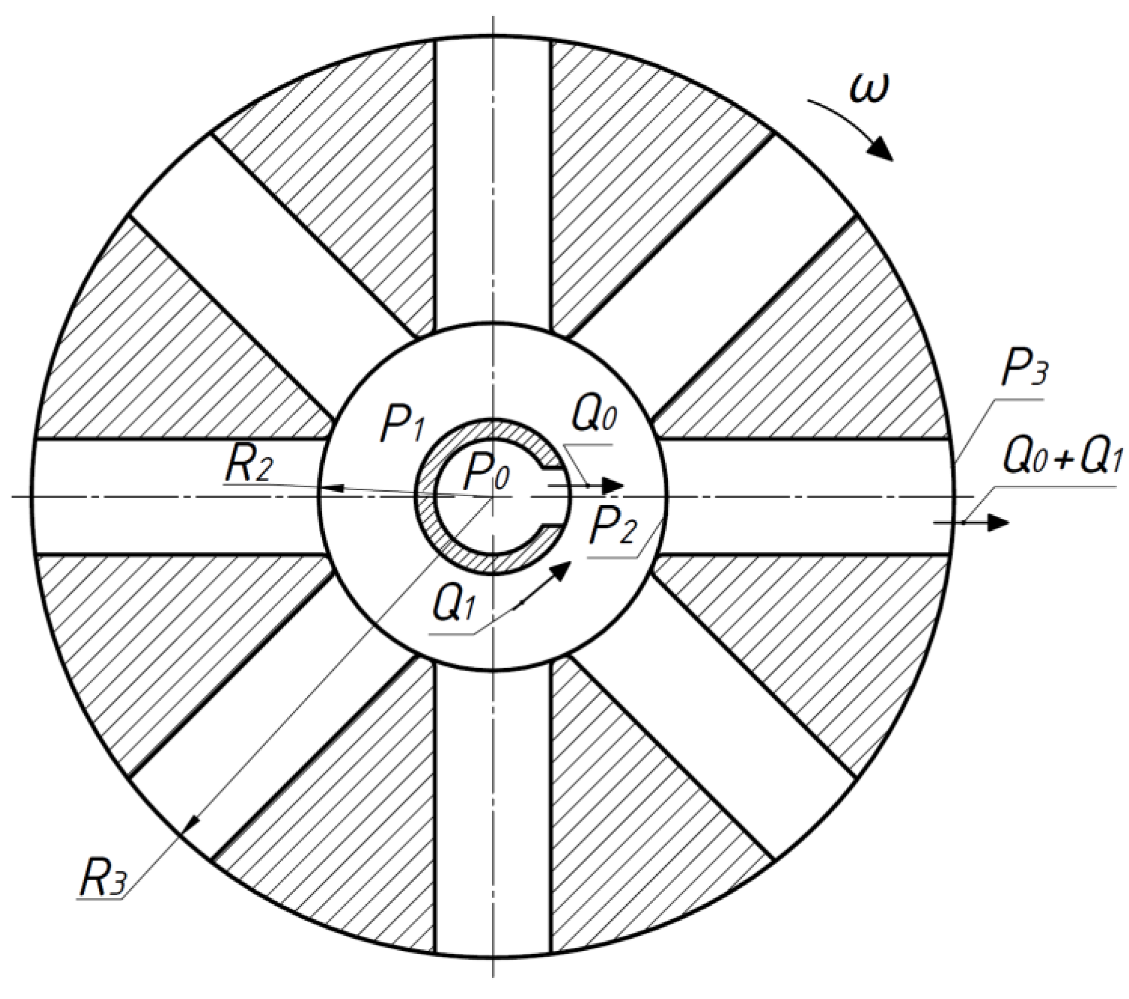
where V 2 u , V 3 u is the circumferential components of absolute flow rate at the inlet into the channel and at the outlet from it; ρ is the fluid density; ω is the angular velocity of the hydraulic machine rotor; R 2 , R 3 is the distance from the center of rotation to the inlet and outlet of the hydraulic machine flow channel.
Let us assume that the jet apparatus can participate in rotary motion together with the rotor of the hydraulic machine and indicate the rotation axis (4) in Figure 4. In this example, the mixing chamber (2) of the jet apparatus acts as a flow channel. Inlet and outlet of the mixing chamber (2) are located at different distances from the rotation axis (4).
First, consider the simplest example, when the longitudinal axis of the mixing chamber passes through the rotor rotation axis, and the inlet and outlet of the mixing chamber are at a distance R 2 , R 3 from the rotation axis, respectively, as shown in Figure 7.
Consider the workflow in a limited area and only inside the mixing chamber, according to Figure 7. When considering an idealized hydraulic machine, there are no hydraulic energy losses. At the inlet and outlet of a cylindrical mixing chamber, the operating characteristics of the flows can be related using Equations (1) and (2). Then let us write down a variant of the equation for a hybrid hydraulic machine, which manifests properties of impeller and jet apparatuses:
Q 0 V c + Q 1 V 2 ( Q 0 + Q 1 ) V 3 f 3 + ρ ( ( ω R 3 ) 2 ( ω R 2 ) 2 ) = P 3 P 2
For description and initial discussion of this theoretical problem, the example presents only one jet apparatus. A physical hydraulic machine’s rotor connects a whole group of jet apparatuses via a parallel scheme, forming flow channels with a mesh structure. This design approach makes it possible to create compact and powerful devices for various purposes. In this case, jet apparatuses’ nozzles are fixed in the central part of the hydraulic machine, and the liquid (gas) enters the rotating mixing chambers in the pulse mode. It is known that, in the channels of the jet apparatus, the pulsed (non-stationary) flow mode is sometimes preferable to the stationary flow mode due to higher operating characteristics [8].
Formula (3) in the above example indicates the possibilities for creating hybrid machines with new technical characteristics. For example, a hybrid pump can be connected to two different energy sources. On the one hand, the rotor rotates using an electric motor. On the other hand, additional energy is supplied through the nozzle (1) (Figure 6), making it possible to increase the pressure in the mixing chamber (2) and at the diffuser (3) outlet, respectively. It is then possible to save electrical energy by partially utilizing the natural reservoir of energy in oil and gas fields. The possibilities of regulating such pumps significantly expand. Even when the rotor stops, this pump can pump liquid (gas or liquid-gas mixture) using the hydraulic energy of power fluid flowing through the nozzle (1).
The hybrid pump shown in Figure 7 can be referred to as a hydraulic machine of the dynamic type. Such hydraulic machines are reversible and can operate in the turbine mode (hydraulic or gas).
The issues regarding the characteristics of gas-dynamic processes in the rotating ejector are of scientific and practical interest. The ejector makes it possible to lower the temperature and velocity of the gas at the mixing chamber’s outlet. Thus, when using new machines, the noise level can be significantly reduced. As the working gas temperature decreases, opportunities open up for using new structural materials with higher strength characteristics but under certain operating temperature limitations. This allows the creation of more efficient turbomachines of various capacities and purposes.
The fundamental Euler Equations (1)–(3) point to additional possibilities for creating new hybrid turbomachinery through the joint use of rotary-vane and vortex workflows. It is also possible to make an interim conclusion that the potential of the Euler turbine has not yet been fully unlocked.

3.3. First Results of Computer Simulation of the Hybrid Turbine Based on Euler Turbine

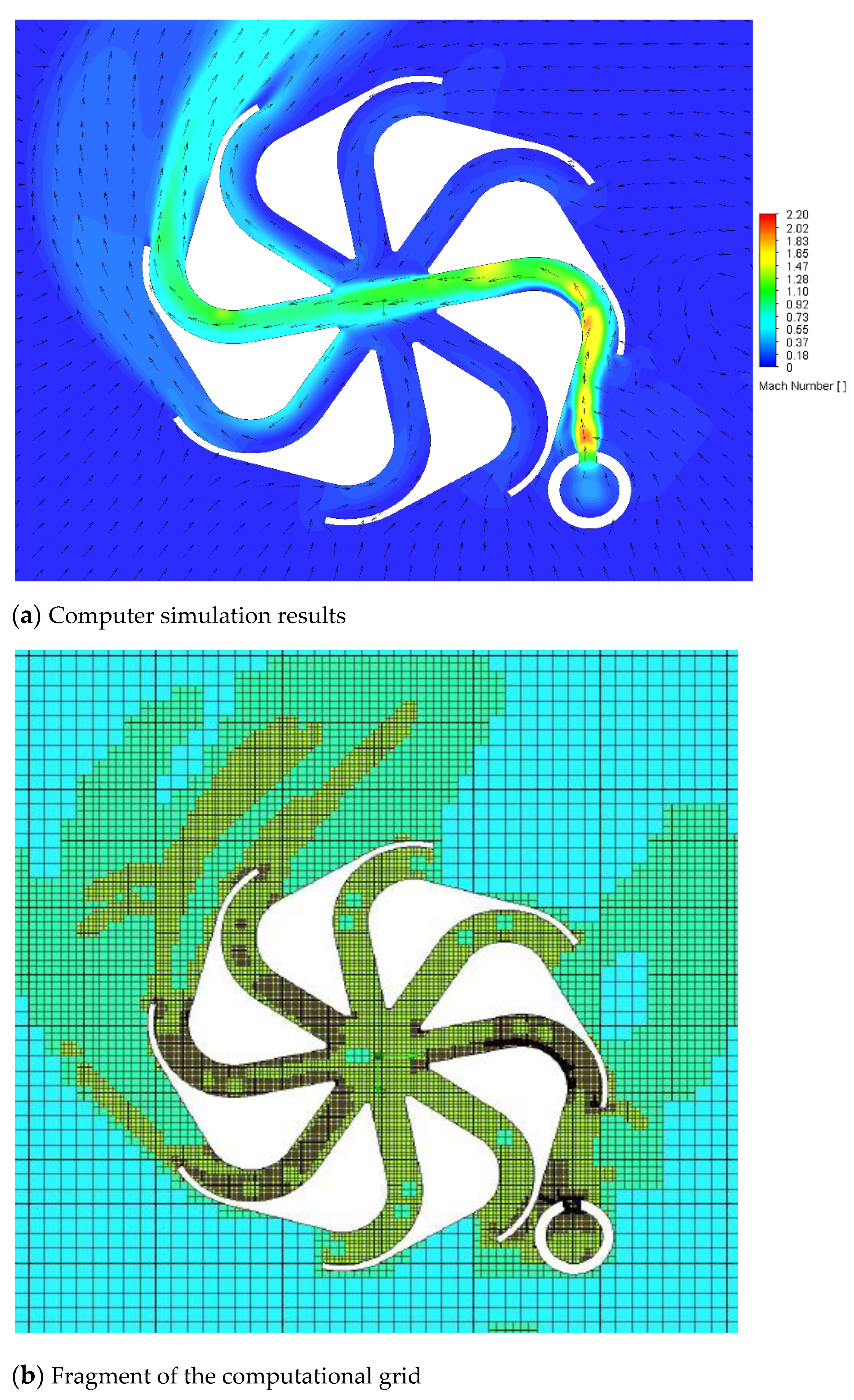
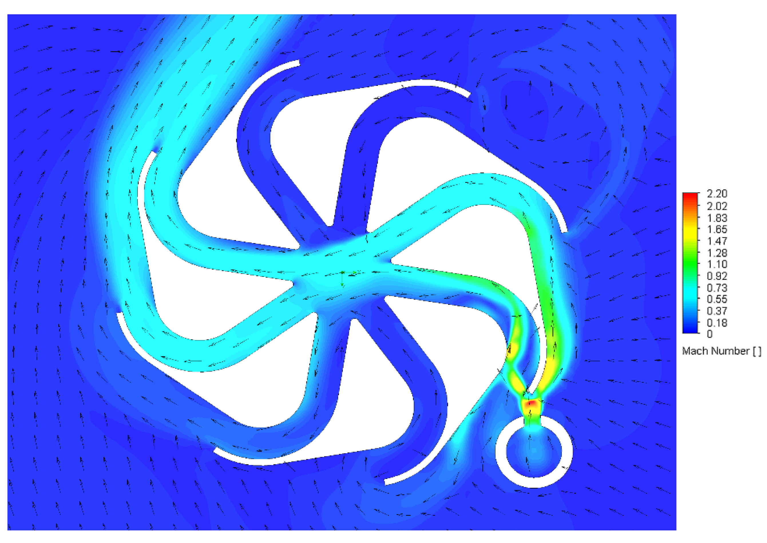
A study of complex gas-dynamic and hydrodynamic processes taking place in the channels of hybrid turbomachines is impossible without computer simulation. The software package Flow Simulation was used to perform computational research. Using the SolidWorks 3D CAD system, 3D models were created. Calculations were performed for the following conditions: working medium, i.e., air with an initial pressure of 0.5 MPa; the pressure at the turbine outlet, i.e., 0.1 MPa; and the rotor diameter, i.e., 80 mm. Figure 8a and Figure 9 show some results of computer simulation of the turbine based on the Euler turbine, taking into account the computational scheme shown in Figure 7. One such turbine is also shown in Figure 4. In this case, the fixed nozzle diaphragm is placed in the central part of the turbine. In this example, two jets of working gas come out of the nozzle diaphragm. There are eight rotating mixing chambers in the rotor cavity. Each jet of the working gas from the nozzle is directed into the mixing chamber, as shown in Figure 8 (operation mode 1), or into two mixing chambers, as shown in Figure 9 (operation mode 2).
Figure 8b shows the 3D computer model and Figure 8c, a fragment of the computational grid.
Figure 9 shows how separating each jet into two mixing chambers lightly impacts the change in torque on the turbine shaft. In the first calculations, the maximum torque on the turbine shaft was determined at zero rotor speed. At this stage of the studies, calculations were made only to check the operability of the proposed versions of the mesh turbine. With continued studies, we plan to select suitable computer calculation programs for a detailed description of the working processes during the rotation of the mesh turbine rotor with plotting design performance.
In the presented turbine, the gas jet is formed with the help of a fixed nozzle diaphragm located in the central part. Then, the gas jet goes to the rotating mixing chambers, and at this, in the mixing chambers, the gas flow mode will be non-stationary. It will also be necessary to take into account that in such a turbine, at the inlet to the rotor, two different gas flows (or two liquid flows) are considered with mass flow rates Q 0 , Q 1 , according to Figure 7. In rotating mixing chambers, these two flows are mixed in pulse mode. At the next stage of research, complex calculation tasks will be solved considering the listed features of the working process. Calculations made for static conditions confirmed the possibility of creating torque in curved mixing chambers. The bench tests of micromodels (prototypes) confirmed the possibility of generating output power during rotation of the rotor of a similar turbine containing many mixing chambers (part of the obtained scientific information was published earlier [1,33]).
Figure 10a and Figure 11 show some results of the computer simulation of the turbine with an external working gas inlet. The fixed nozzle diaphragm is located outside the rotor. In this example, one jet of working gas comes out of the nozzle diaphragm. There are eight rotating mixing chambers in the rotor cavity. The jet of working gas from the nozzle goes into the mixing chamber, as shown in Figure 10 (operation mode 3), or into two mixing chambers, as shown in Figure 11 (Operation mode 4). Figure 10b shows a fragment of the computational grid.
The calculations showed that with an external working gas inlet, the separation of the gas jet into two mixing chambers (Figure 11) has little effect on the change in torque on the turbine shaft. For the rest of the working time, the gas jet is directed only into one mixing chamber, and the torque on the turbine shaft practically does not change at any angular displacement of the rotor relative to the fixed nozzle. A preliminary conclusion can be made that the turbine will remain operational with a pulsed short-term change in torque by 10%... 15%.

3.4. Development of Machine Prototypes with Mesh Structure of Flow Channels

The computer simulation results were used to develop the turbine prototypes shown in Figure 8, Figure 9, Figure 10 and Figure 11. Turbine prototypes (micromodels with rotor diameters ranging from 50 mm to 80 mm, more than 20 different variants) were manufactured using additive technologies. These turbine micromodels were tested under laboratory conditions. Water and air were the working media. The tests of the micromodels confirmed the workability of the new turbines and provided experimental data for the development of research work. At this stage of the study, it would be sufficient to state that the results obtained apply to prototypes. Further studies are neededto clarify the applicability of similarity theory with the determination of coefficients for the conversion of working parameters in the transition from micromodels to real industrial samples.
Ejectors used as jet (reactive) augmenters are well known [9], but little information has been published on the use of the ejector as a damper and as a system for thrust vector control. Figure 12 shows the experimental ejector that was created by the authors to study the process of thrust vector control. For known control systems, the deflection angle of the thrust vector can vary a maximum of +20° to −20° [34,35,36]. However, based on laboratory test results, it can take any value from +90° to −90° in any direction (i.e., within a hemisphere) [1,37]. The design of an adjustable nozzle using a deflector made as a diaphragm is known [38]. This diaphragm can be used to control the ejector’s operation. Conducted laboratory experiments also showed that the ejector allows infinite thrust control from 0% to 100% of the maximum thrust value. This advantage can also be used in the creation of hybrid turbines to regulate the torque on the turbine shaft.
It may also be noted that, due to the complexity and insufficient study of gas-dynamic processes, the interest in studying various processes of interaction of a gas jet with a barrier does not weaken [23,39,40,41,42].
Micromodels of mesh turbines, pumps, and fans were created with the use of additive technologies. Figure 13 shows one of the variants of the new turbine [32]. The developed turbine can be attributed to the group of pulse turbines [43,44,45].
Figure 14 graphically shows one variant of the hybrid turbopump.
As part of ongoing research, variants of known turbopumps, pumps, and compressors were also studied. When studying turbopumps, special attention can be paid to labyrinth screw pumps. Labyrinth screw pumps are very effective for high-viscosity fluids and liquids with a high content of mechanical impurities in the flow. However, labyrinth screw pumps have fewer pump heads than centrifugal pumps, all other things being equal.
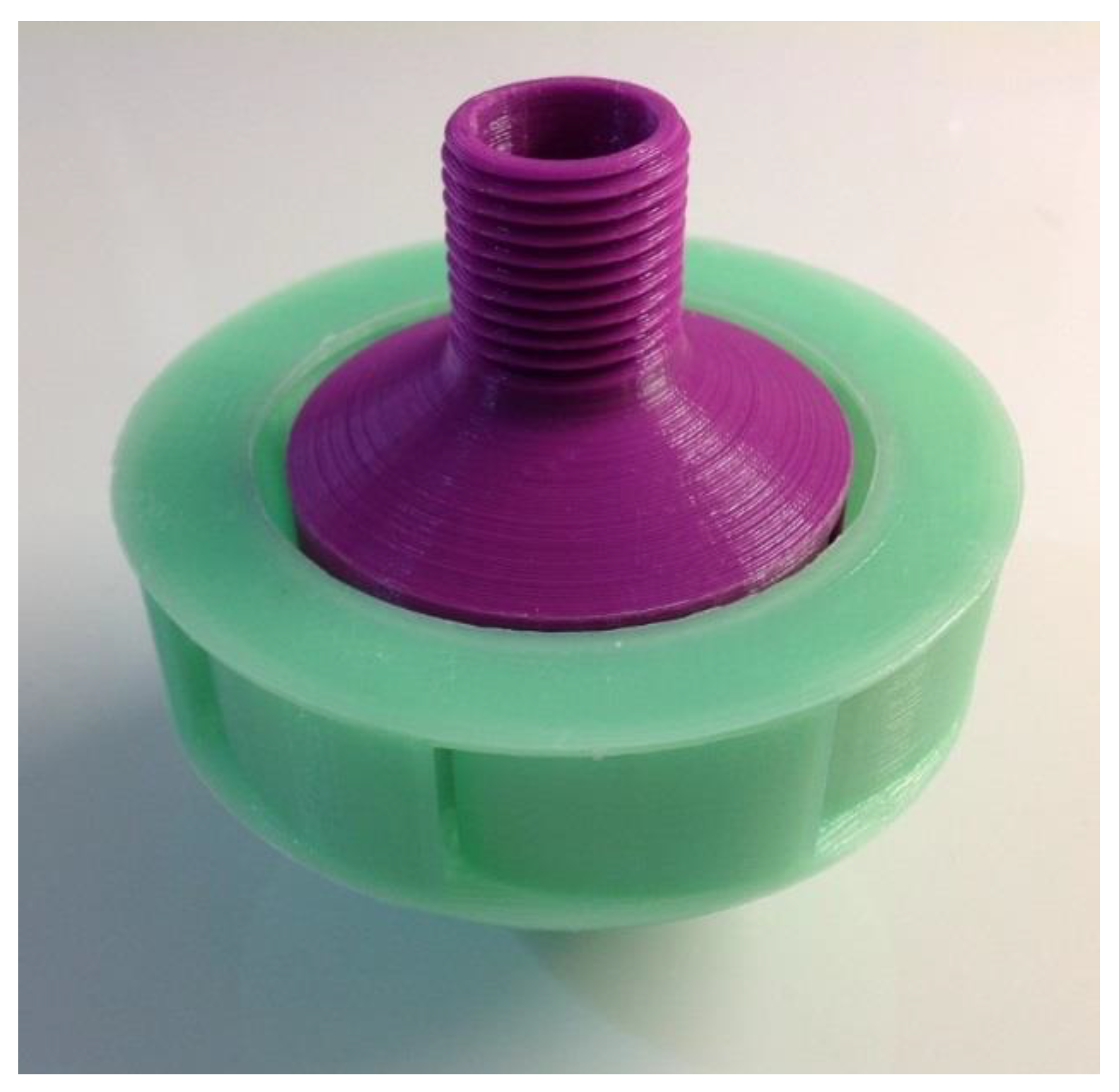
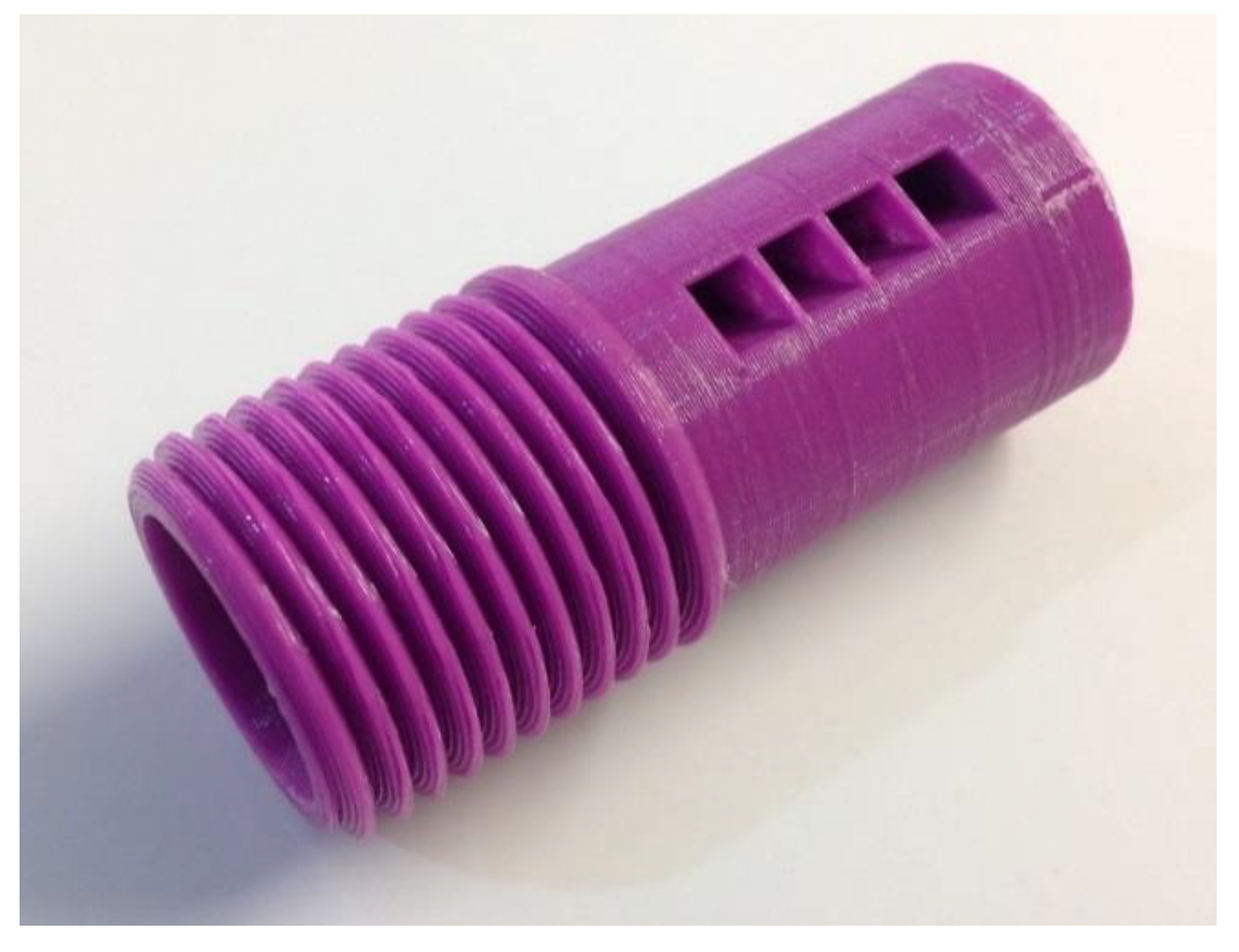
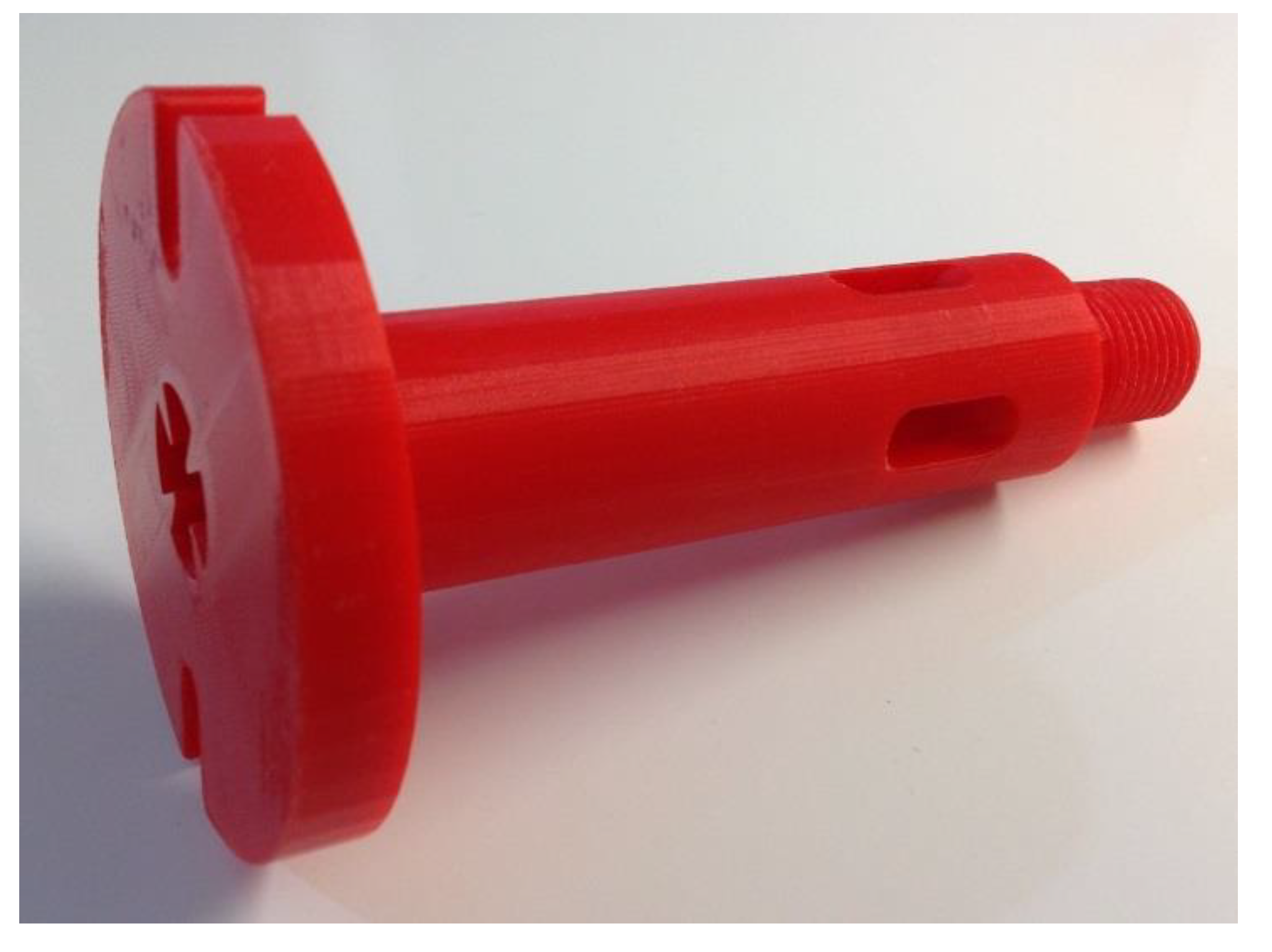
As part of the research, work has been performed to develop new hybrid labyrinth pumps that combine the best qualities of labyrinth screw pumps and centrifugal pumps. During the study, a prototype of a new labyrinth pump was manufactured using FDM 3D printing. Figure 15 and Figure 16 show its parts.

3.5. Results of Laboratory Tests of Hybrid Pump Prototype

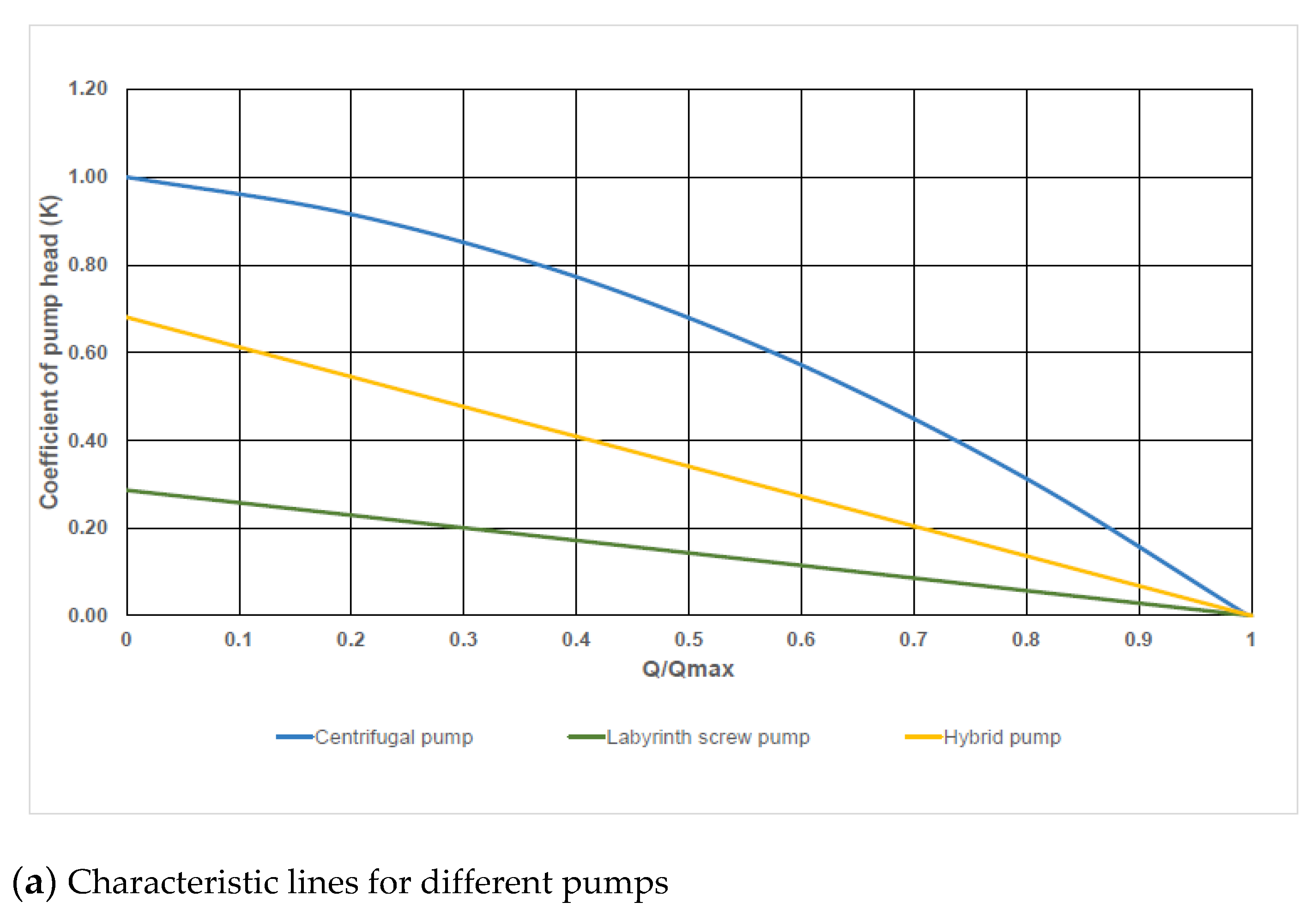
The results of laboratory tests revealed that the new hybrid pumps have a higher head and retain the positive qualities of the classical labyrinth screw pumps (Figure 17).
Figure 17a shows a comparison of the head factors (K) for the labyrinth pump, centrifugal pump, and hybrid pump. A dimensionless parameter (Q/Qmax) equal to the pump supply ratio (Q) to the maximum pump supply (Qmax) is used to estimate the pump operating mode.
Coefficient of pump head: K = ( H / L ) / ( H 1 / L 1 ) , where H is the pump head, L is the installation length of the pump, H1 is the maximum head of a commercially available centrifugal pump, and L1 is the installation length of a commercially available centrifugal pump.
The maximum head of the commercially available centrifugal pump (H1) corresponds to the operating mode at which the pump supply is zero, Q = 0.
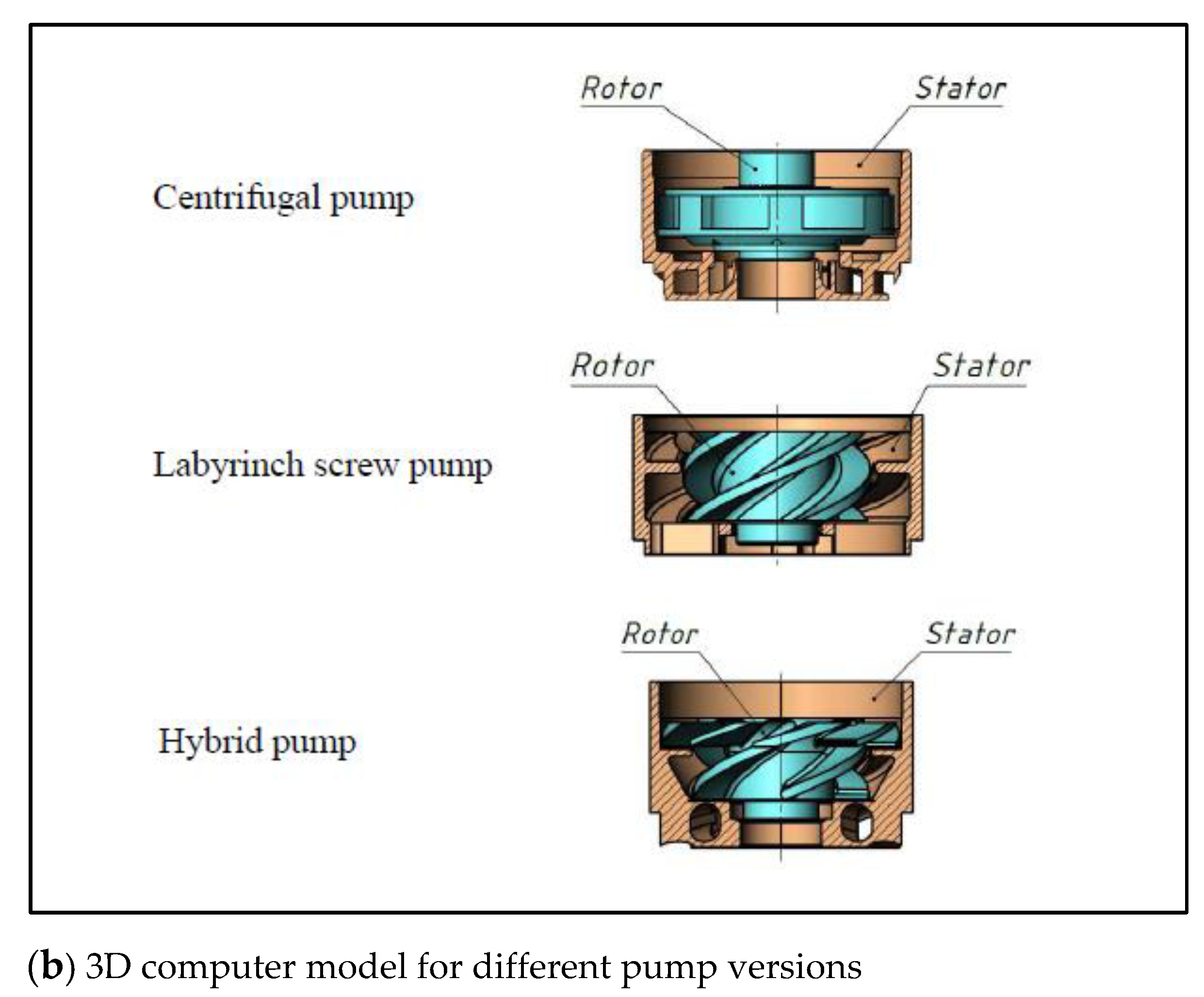
In Figure 17a, the hybrid pump characteristic line is between the labyrinth and centrifugal pump characteristic lines. This also indirectly indicates the hybrid nature of the new pumps, which combine the qualities of both centrifugal pumps and labyrinth pumps. Figure 17b shows the 3D computer model for different pump versions.
When pumping high-viscosity media, the new hybrid labyrinth pumps are more efficient than centrifugal pumps.

3.6. Results of Experimental Centrifugal Pump Studies

The study of turbopumps also considers some issues in the design of multistage centrifugal pumps with open impellers. Such impellers make it possible to create more compact pump plants for complicated operating conditions. This information is necessary for comparative assessments of the new technology and creating new turbopumps with a mesh structure of flow channels.
The following problems were solved:
  • Creation of a digital model of a centrifugal pump stage with an open impeller;
  • Determination of the theoretical performance characteristics of the pump stage during the virtual experiment and computer simulation;
  • Determination of the experimental performance of the pump stage during the full-scale experiment on the laboratory bench;
  • Comparison of the results of the virtual experiment with those of the full-scale experiment;
  • Theoretical research of the impact of pumped medium viscosity on the axial force acting on the open impeller.
The geometric digital model of the pump stage was created in the SolidWorks solid geometric modeling system. The outer diameter of the guiding device was 60 mm. The dimensions of the impeller and guiding device were chosen for an optimum supply of 40 m3/day.
The computational fluid dynamics (CFD) software package SolidWorks Flow Simulation was used for the theoretical (computational) research, followed by a verification of the computational results by field tests.
A numerical model was used to investigate the field and integral characteristics of the single-phase flow inside the fluid passages of the impeller and guiding device for a three-stage model. The trend of characteristic changes in all pump stages was monitored.
The study requires determining the pump head, efficiency, power consumption, and axial force at different pump outputs and densities and viscosities of the pumped medium.
The approximation of a one-component incompressible medium described by Navier–Stokes equations given the non-Darcy effects was used to simulate the fluid motion (the physical models are explained in detail in the descriptions technical reference [46,47]). The flow was calculated as a transient between the laminar and turbulent states in the entire computational region (depending on the flow characteristics). By default, the turbulence parameters were set automatically. Flow Simulation utilizes the k-ε model of turbulence, with built-in methods which make it possible to obtain a sufficiently accurate boundary layer solution for such and most other similar problems, even on a coarse mesh. The accuracy is achieved by the Two-Scales Wall Functions (2SWF) implemented in Flow Simulation [46,47,48]. The type and thickness of the boundary layer are determined using Flow Simulation, depending on the Reynolds number; the effective length of the wall, also depending on the Reynolds number, is taken into account here.
The Two-Scales Wall Functions (2SWF) model in Flow Simulation [47] consist of two approaches to coupling the boundary layer calculation with the main flow properties:
  • To describe boundary layers on a fine mesh (the number of cells across a boundary layer is six or greater) the “thick-boundary-layer” approach is used. In this approach the calculation of parameters of laminar boundary layer is doing via Navier-Stokes equations and for the turbulent boundary layer is performed by modification of well-known wall function approach. However instead of the classical approach where the logarithmic velocity profile is used in EFD technology the full profile proposed by Van Driest [47,49] is used. All other assumptions are similar ones to the classical wall functions approach;
  • The “thin-boundary-layer” approach is used to describe flow on a coarse mesh (the number of cells across a boundary layer is four or less). In this approach the Prandtl boundary layer equations already integrated along the normal to the wall from 0 (at the wall) to the dynamic boundary layer thickness (δ) are solved along a fluid streamline covering the walls. If the boundary layer is laminar these equations are solved with a method of successive approximations based on the Shvetz trial functions technology [47,50]. If the boundary layer is turbulent or transitional between laminar and turbulent, a generalization of this method to such boundary layers employing the Van Driest hypothesis about the mixing length in turbulent boundary layers is used [47,49];
  • In intermediate cases, a compilation of the two above approaches is used, ensuring a smooth transition between the two models as the mesh is refined, or as the boundary layer thickens along a surface.
By default, an appropriate boundary-layer approach is selected automatically according to the computational mesh.
The problem is solved using the following assumptions: the calculation of heat exchange in the flow is not considered, and the fluid medium is assumed to be incompressible. Note that in Navier–Stokes equations related to an incompressible fluid, the pressure is defined with regard to the accuracy to a constant. Consequently, the flow parameters at each stage of the submersible pump are identical, and the pressure differs by a constant (pressure drop at the stage). Thus, it is enough to calculate the values for only a single pump stage to secure reliable values for the required characteristics at all the remaining stages located along the entire length of the pump.
The formulation of the task for the virtual experiment is as follows. Water is fed into the centrifugal stage consisting of impeller and guide vanes. Water density and viscosity are library parameters and are recalculated by the program depending on temperature. The roughness of the impeller surfaces and guide vanes was assumed in the range Rz = 30–350 μm, depending on the manufacturing technology (3D printing, casting, milling) and depending on the structural materials used (plastic, metal). The impeller speed was set to 1500, 2900, 4500, and 6000 rpm.
A structured Cartesian grid was generated to perform the calculation. Sliding grid technology was used to simulate rotation through the creation of three local rotating areas according to the number of impellers. Additionally, three local grids were set for the areas around the fixed stator vanes. In the local areas, a higher level of grid fragmentation was set. The total number of grid elements was in the range of 1.5–2.5 million cells. The results of the grid independence calculation at a point with optimum output were satisfactory for this grid. The time required to calculate the value for one point was about 3–10 h, depending on the vortex formation and grid density. The SolidWorks Flow Simulation package applied grid adaptation to the flow gradients in the computational region during the calculation process.
The problem was solved in the non-stationary setting. The time step size was chosen equal to 1° and was the same for all rotational velocities. The required calculation values, particularly the pressure, were obtained from the average value after achieving periodicity in the simulation, and when the change in the absolute value of the variables did not exceed 1–5%. Moreover, in the working range of feeds, the scatter of values was minimal. The convergence, as a rule, was achieved after 3–5 rotations of the impeller.
Experimental characteristics of the pump were determined by conducting standard energy tests on the laboratory bench. Figure 2 shows the laboratory bench diagram.
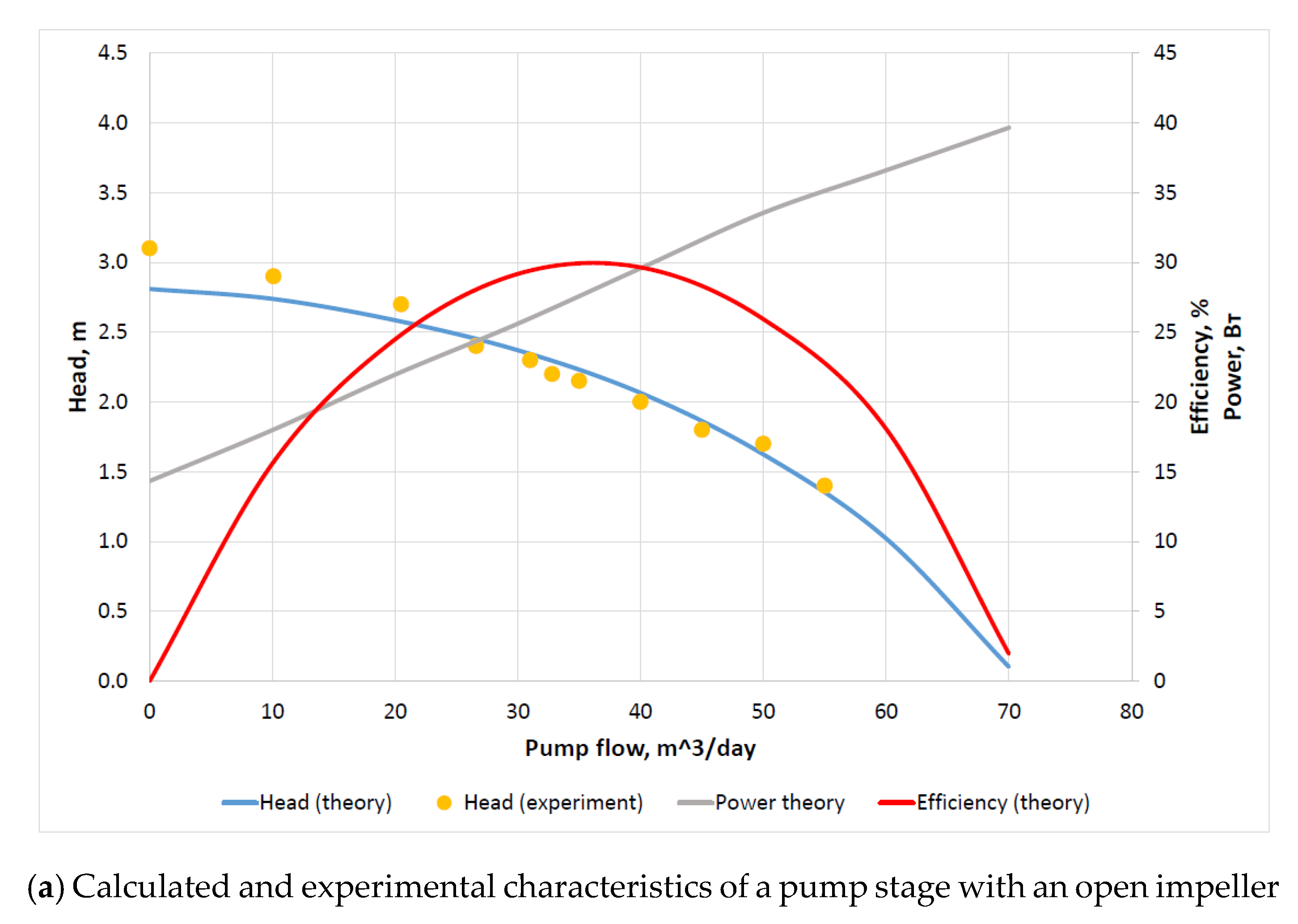
Figure 18 and Figure 19 show the research results. Figure 18b shows the 3D computer model and Figure 18c shows an example of the fragments of the initial calculation grid before adaptation.
The calculation is based on three pump stages, and the operating characteristics are taken from the second and third stages. The results of the first stage calculation were not taken into account since due to the lack of flow twist at the inlet there are significant differences in the characteristics of the first stage compared to the second and third stages.
In Figure 18a, the solid lines reflect the results of computer simulation of the pump during fresh water pumping. The yellow points reflect the head values obtained during the physical experiments in the bench pump test (working medium–water). A theoretical characteristic was built, and a comparison was made with the results of physical experiments obtained in the bench pump test to verify the adequacy of the CFD calculation, performed on a three-stage computer model.
Figure 19 shows the theoretical data (i.e., the results of the CFD calculation).
The roughness of the impeller surface has little effect on the CFD calculation results, while an increase in surface roughness of the guide device leads to a significant drop of pump head and efficiency and an increase in power consumption.
The graphical dependencies in Figure 19 indicate the interrelation of pump output and axial force acting on the open impeller at different values of the pumped liquid viscosity (the liquid density −900 kg/m3): minor viscosity (1 cP), low viscosity (5 cP), and higher viscosity (10 cP). Calculation results show that an increase in viscosity between 1 and 10 centipoises (cP) leads to a significant decrease in axial force.
The research results of experimental centrifugal pump (with an open impeller) are planned to use in the design of new turbomachinery with a mesh structure of flow channels.

4. Discussion

When developing new jet systems in this study, research results from various industries, including aviation and space technologies, are utilized to expedite the process. When developing new turbomachines, we decided to consider many interrelated processes and conditions including [2]: rotary-vane and vortex workflows; pump and turbine workflows; coalescence and dispersion; cavitation in liquid and a gas-liquid mixture; separation in multiphase media; the presence of solid particles in the flow; a point or distributed energy supply; series and parallel connection of machines; single-stage or multistage machines; hydraulic friction and shock losses with a partial pressure recovery process; constant and variable coefficients of resistance; development or damping of separate processes in different points of the machine’s working chamber with a change of the fluid flow rate; changes in physical properties of a liquid or gas-liquid mixture in various points of the machine’s flow part; the presence of axial symmetry for solid walls and a flow; used methods of machine regulation; and steady and pulsed flow modes in separate zones. Given the diversity and complexity of these issues, it is possible to talk about the bright prospects of computer technology application in the design of new turbomachines. When discussing hybrid machines, questions about the need for interdisciplinary research necessarily arise.
By analyzing the information published by various authors, it is also possible to consider some judgments about the scientific data on jet technology in general and on ejectors in particular:
  • Ejector designs with one mixing chamber and several nozzles located at the inlet to the mixing chamber or along the mixing chamber are known, but ejector designs with one nozzle and several mixing chambers (multi-flow ejector) are little known; in this case, the working medium can be supplied from the nozzle to one mixing chamber or several mixing chambers simultaneously;
  • The designs of the ejector with cylindrical or conical mixing chambers are known, but designs with curved mixing chambers are little known [51,52];
  • Ejectors as augmenters in jet propulsions (in aviation and water transport) are known, but these with a range of control from the maximum thrust value to zero one are little known;
  • Ejectors, in which the nozzle and mixing chamber location does not change over time, are known, but ejectors in which these parts location changes over time are little known;
  • Ejectors with a stationary mode of fluid flow through the nozzle and mixing chamber are known, but ejectors with a non-stationary mode are little known;
  • Theories are known to describe ejector workflows for homogeneous media when properties of the working medium and the pumped medium coincide, but theories are little known to describe processes when these properties differ significantly (in density, temperature, and viscosity).
For the current level of science and technology, we can conclude that there are issues in the ejector theory that require additional research: for conditions where the ejector (or only its mixing chamber) rotates as the turbomachine rotor part and for conditions where several ejectors form a grid structure of flow channels. However, with the use of computer technology, rapid advances in the study of jet technology can be expected, accompanied by the imminent breakthrough of new technologies.
The presented paper considers some features of the operation of an ejector consisting of one nozzle and several mixing chambers, where the working medium (gas, liquid, or a gas-liquid mixture) from the nozzle can be directed to all of the mixing chambers (with a uniform or a non-uniform distribution) or a single mixing chamber. The chambers can be fixed or movable (with linear or rotational motion). The nozzle diaphragm in such an ejector can also be fixed or movable, with the ability to control flows in the mixing chamber channels. The flow mode in the mixing chambers can be stationary or non-stationary.
Based on the computer simulation results, conclusions were drawn about the prospects of hybrid turbomachines capable of operating in both turbine and compressor or pump modes. Using additive technologies, various micromodels of turbines, including the Euler turbine, have been created. Laboratory hydraulic tests showed that the liquid inlet to the rotor could also operate in pulse mode. In addition, laboratory tests of micromodels were carried out using compressed air. It is shown that gas (or liquid) motion through curved pipes can be carried out from the rotor periphery to its center and then back to the rotor periphery but through another curved pipe.
The Euler turbine can be seen as an analog (or prototype) for creating a new class of turbines, pumps, and compressors in which rotary-vane and vortex (ejection) workflows take place simultaneously. The results of the conducted work show that the scientific and technical potential of the Euler turbine has not yet been fully unlocked, and research work in this direction should continue.
The round, square, plane, and radial air (annular) jets have been investigated most extensively [53]. Scientific publications present results of the research and development of new nozzle configurations of annular rocket engines (with internal and external flow expansion) for dense configurations of advanced missile stages and spacecraft [54]. The results of these studies show that known gas-dynamic methods of thrust vector control can be effectively used in expansion-deflection nozzles. The existence of a relatively small-sized central body in this nozzle makes it possible to use new mechanical methods based on transverse displacement or oscillation of the central body.
To date, the scientific and technical potential of hydrodynamic and gas-dynamic systems in controlling processes associated with changes in the fluid or gas flow direction, including the consideration of magneto-hydrodynamic control systems [55], has not been fully explored.
Developments in research will involve the study of acoustic characteristics of mesh turbines and nozzles. Modern calculation methods make it possible to solve specific problems. We already know the results of experimental studies of the acoustic characteristics of subsonic turbulent jets flowing from rectangular nozzles. They show that the directivity of sound radiation and noise spectra in the far acoustic field of such jets are close to the characteristics of a jet flowing from a round nozzle [56].
The research results can be used in various industries, including energy, aviation, water transport, and robotics.
Further research will focus on the study of mesh turbomachines and mesh jet systems with a pulsed flow regime of liquids and gases.

5. Conclusion

5.1. Scientific Novelty

We studied the features of gas and liquid flow in the channels of turbines, made by analogy with the Euler turbine. We also studied the gas-dynamic and hydrodynamic processes in hybrid turbomachines during numerical and physical experiments with the qualities of vane machines and ejectors. We developed the basic principles for implementing the ejector process in the channels of a turbomachine and a prototype of a jet system operating with the rotation of several mixing chambers in the ejector.

5.2. Theoretical Contribution

Based on Euler’s legacy, we have proposed a scientific direction to develop the theory of hybrid turbomachines, in which the rotary-vane workflow and the vortex ejection workflow are jointly implemented. Preliminary results of numerical and physical experiments indicate the feasibility of creating this new theory.

5.3. Practical Importance

The results of ongoing scientific research can be used to improve the energy efficiency of turbomachines and jet systems operating in complicated conditions with limitations on temperature and flow rate concerning various technological systems including onshore, offshore, and aviation systems.

5.4. Limitations and Future Studies

Studies of gas jets are carried out using channels with traditional geometric shapes in a limited area, including circular, square, flat, and annular jets. Further research should involve studying gas flows in channels with unconventional forms, including mesh channels in turbomachines and ejectors under stationary and non-stationary modes.

Author Contributions

Conceptualization, Y.A.S. and M.A.M.; methodology, Y.A.S., M.A.M. and I.V.G.; software, Y.A.S., V.V.M., K.A.T. and M.A.F.; validation, Y.A.S., I.V.G. and V.V.V.; formal analysis, M.A.M., I.V.G. and V.V.V.; investigation, Y.A.S., M.A.M., K.A.T., M.A.F. and N.N.B.; resources, Y.A.S., M.A.M., I.V.G., V.V.V., V.V.M., K.A.T., M.A.F. and N.N.B.; data curation, Y.A.S., M.A.M. and I.V.G.; writing—original draft preparation, Y.A.S., K.A.T. and M.A.F.; writing—review and editing, Y.A.S., M.A.M., I.V.G., V.V.V., V.V.M. and N.N.B.; visualization, Y.A.S., V.V.M., K.A.T. and M.A.F.; supervision, Y.A.S., I.V.G. and V.V.V.; project administration, Y.A.S. All authors have read and agreed to the published version of the manuscript.

Funding

The work has been performed with the financial support of the Ministry of Education and Science of the Russian Federation within the framework of the state contract in the area of scientific activities, topic number FSZE-2020-0006.

Acknowledgments

The work has been performed with the financial support of the Ministry of Education and Science of the Russian Federation within the framework of the state contract in the area of scientific activities, topic number FSZE-2020-0006. The work has been performed using a set of equipment for hydrodynamic and gas-dynamic research in the design of pumping and compressor technologies, which is part of the Common Use Center “Hydrocarbon Exploration and Production” of the FSAEI HE “Gubkin University”.

Conflicts of Interest

The authors declare no conflict of interest.

References

  1. Sazonov, Y.A.; Mokhov, M.A.; Tumanyan, K.A.; Frankov, M.A.; Balaka, N.N. Prototyping mesh turbine with the jet control system. Periódico Tchê Química 2020, 17, 1160–1175. [Google Scholar] [CrossRef]
  2. Sazonov, Y.A. Fundamentals of Calculation and Design of Pump-Ejector Installations; SUE “Oil and Gas Publishing House” of Gubkin University: Moscow, Russia, 2012. [Google Scholar]
  3. Konovalova, N.E. Calculation of the minimum drag of lattice wings and their elements and comparison of the calculated results with the experiment at M = 0.6 ÷ 4.0. Air Fleet Tech. 2005, 2, 36–43. [Google Scholar]
  4. Drozdov, S.M. Method of determining the full-scale aerodynamic performance of an airplane with lattice wings based on the results of its model wind-channel tests. TsAGI Sci. J. 2002, 33, 18–29. [Google Scholar]
  5. Kostyukov, A.V.; Nadarejshvili, G.G.; Karpukhin, K.E.; Tuktakiev, G.S.; Azarov, K.O. High-Temperature Rotating Disk Regenerative Heater of the Working Body of the Power Plant. RF Patent 2,744,926. Available online: https://patenton.ru/patent/RU2744926C1.pdf (accessed on 10 April 2021).
  6. Orman, Ł.J. Aspects of complexity of metal-fibrous microstructure for the construction of high-performance heat exchangers: Thermal properties. Aviation 2020, 24, 99–104. [Google Scholar] [CrossRef]
  7. Giuliani, F.; Stütz, M.; Paulitsch, N.; Andracher, L. Forcing pulsations by means of a siren for gas turbine applications. Int. J. Turbomach. Propuls. Power 2020, 5, 9. [Google Scholar] [CrossRef]
  8. Kalachev, V.V. Jet Pumps. Theory, Calculation, and Design; Filin, Omega-L: Moscow, Russia, 2017. [Google Scholar]
  9. Bogdanov, V.I.; Dormidontov, A.K.; Yakovlev, V.V. Ejector Augmenter. RF Utility Model Patent 202,545, 24 February 2021. [Google Scholar]
  10. Enrico, B.; Rocco, F.; Lapo, G.; Enrico, M.; Alessandro, R.; Andrea, R.; Yary, V. Toward the integration of lattice structure-based topology optimization and additive manufacturing for the design of turbomachinery components. Adv. Mech. Eng. 2019, 11, 1–14. [Google Scholar] [CrossRef] [Green Version]
  11. Zhang, Y.; Fi, L.; Jia, D. Lightweight design and static analysis of lattice compressor impeller. Nature 2020, 10, 1–10. [Google Scholar] [CrossRef] [PubMed]
  12. Magerramova, L.; Volkov, M.; Afonin, A.; Svinareva, M.; Kalinin, D. Application of Light Lattice Structures for Gas Turbine Engine Fan Blades. In Proceedings of the 31st Congress of the International Council of the Aeronautical Sciences, Belo Horizonte, Brasil, 9–14 September 2018; The International Council of the Aeronautical Sciences: Belo Horizonte, Brasil, 2018. [Google Scholar]
  13. Krasnova, E.V.; Saushkin, B.P. Additive shaping of products from metals and alloys by an electron beam. Selective melting (Part 1). Addit. Technol. 2021, 2, 44–57. [Google Scholar]
  14. Ignatkin, Y.; Makeev, P.; Konstantinov, S.; Shomov, A. Modelling the helicopter rotor aerodynamics at forward flight with free wake model and urans method. Aviation 2020, 24, 149–156. [Google Scholar] [CrossRef]
  15. Sun, Z.; Wang, B.; Zheng, X.; Kawakubo, T.; Tamaki, H.; Numakura, R. Effect of bent inlet pipe on the flow instability behavior of centrifugal compressors. Chin. J. Aeronaut. 2020, 33, 2099–2109. [Google Scholar] [CrossRef]
  16. Sieverding, C.; Manna, M. A review on turbine trailing edge flow. Int. J. Turbomach. Propuls. Power 2020, 5, 10. [Google Scholar] [CrossRef]
  17. Abbasi, W.S.; Islam, S.U.; Lubna, F.A.; Rahman, H. Numerical investigation of transitions in flow states and variation in aerodynamic forces for flow around square cylinders arranged inline. Chin. J. Aeronaut. 2018, 31, 2111–2123. [Google Scholar] [CrossRef]
  18. Neigapula, S.N.V.; Maddula, S.P.; Nukala, V.B. A study of high lift aerodynamic devices on commercial aircrafts. Aviation 2020, 24, 123–136. [Google Scholar] [CrossRef]
  19. Zhang, J.; Sun, L.; Qu, X.; Wang, L. Time-Varying linear control for tilt rotor aircraft. Chin. J. Aeronaut. 2018, 31, 632–642. [Google Scholar] [CrossRef]
  20. Sinyavin, A.A. Calculation and Experimental Study of the Interaction of Gas Flows with Permeable Boundaries. Ph.D. Thesis, Lomonosov Moscow State University, Moscow, Russia, 2010. [Google Scholar]
  21. Xue, Y.; Wang, L.; Fu, S. Detached-Eddy simulation of supersonic flow past a spike-tipped blunt nose. Chin. J. Aeronaut. 2018, 31, 1815–1821. [Google Scholar] [CrossRef]
  22. Raj, C.A.S.; Narasimhavaradhan, M.; Vaishnavi, N.; Arunvinthan, S.; Al Arjani, A.; Pillai, S.N. Aerodynamics of ducted re-entry vehicles. Chin. J. Aeronaut. 2020, 33, 1837–1849. [Google Scholar] [CrossRef]
  23. Glaznev, V.N.; Zapryagaev, V.I.; Uskov, V.N.; Terekhova, N.M.; Erofeev, V.K.; Grigoryev, V.V.; Kozhemyakin, A.O.; Kotenok, V.A.; Omelchenko, A.V. Jet and Nonstationary Flows in Gas Dynamics; The Siberian Branch of the Russian Academy of Sciences: Novosibirsk, Russia, 2000. [Google Scholar]
  24. Garbaruk, A.V. Numerical Modeling and Stability Analysis of Near-Wall Turbulent Flows. Doctoral Thesis, Peter the Great St. Petersburg Polytechnic University, St. Petersburg, Russia, 2020. [Google Scholar]
  25. Akimov, G.A.; Vavilov, D.O.; Klochkov, A.V. Numerical study of supersonic jets of complex spatial configuration. Rocket. Eng. 2010. Available online: https://missilery.info/article/chislennoe-issledovanie-sverhzvukovyh-struy-slozhnoy-prostranstvennoy-konfiguracii (accessed on 10 April 2021).
  26. Antipova, M.S.; Dyadkin, A.A.; Zapryagaev, V.I.; Krylov, A.N. Computer simulation of cold supersonic jet outflow from the conical nozzle using FLOEFD software package. Space Eng. Technol. 2016, 1, 5–11. [Google Scholar]
  27. Skaggs, B.D. Fluid Jet Ejector and Ejection Method. U.S. Patent 6,017,195. Available online: https://www.freepatentsonline.com/6017195.pdf (accessed on 10 April 2021).
  28. Dodge, A.Y. Jet Pump. U.S. Patent 3,188,976. Available online: https://www.freepatentsonline.com/3188976.pdf (accessed on 10 April 2021).
  29. Letvin, S. Process for Scrubbing a Gas Stream Containing Particulate Material. U.S. Patent 3,385,030. Available online: https://www.freepatentsonline.com/3385030.pdf (accessed on 10 April 2021).
  30. Berezhnoy, A.S. Improving the Performance of Jet Reaction Pneumatic Unit Based on the Model Update of the Work Process. Ph.D. Thesis, Sumy State University, Sumy, Ukraine, 2014. [Google Scholar]
  31. Sazonov, Y.A.; Mokhov, M.A.; Tumanyan, K.A.; Frankov, M.A.; Timoshenko, V.G. Motor. RF Utility Model Patent 192,513. Available online: https://yandex.ru/patents/doc/RU192513U1_20190918 (accessed on 10 April 2021).
  32. Sazonov, Y.A.; Mokhov, M.A.; Tumanyan, K.A.; Voronova, V.V.; Frankov, M.A. Motor. RF Patent 203,833. Available online: https://yandex.ru/patents/doc/RU203833U1_20210422 (accessed on 10 April 2021).
  33. Sazonov, A.Y.; Mokhov, M.A.; Mulenko, V.V.; Frankov, A.M.; Tumanyan, K.A.; Voronova, V.V. Exploratory research for developing advanced pumping and compressor equipment adapted to abnormal operating conditions of oil and gas production. J. Appl. Eng. Sci. 2020, 18, 467–474. [Google Scholar] [CrossRef]
  34. Missile Control Systems Aerospaceweb. Available online: http://www.aerospaceweb.org/question/weapons/q0158.shtml (accessed on 10 April 2021).
  35. Abugov, D.I.; Bobylev, V.M. Theory and Calculation of Solid Rocket Motors; Textbook for Mechanical Engineering Universities, Mechanical Engineering: Moscow, Russia, 1987. [Google Scholar]
  36. Bailey, J.M. Control System and Nozzle for Impulse Turbines. U.S. Patent 4,355,949. Available online: https://www.freepatentsonline.com/4355949.pdf (accessed on 10 April 2021).
  37. Sazonov, Y.A.; Mokhov, M.A.; Gryaznova, I.A.; Voronova, V.V.; Tumanyan, K.A.; Frankov, M.A.; Moon, V.A.; Balaka, N.N. Prototype development of intelligent mesh turbine using the ejector control system. Gas Ind. 2020, 11, 52–59. [Google Scholar]
  38. Chanut, P.L.J. Guided Missile. U.S. Patent 3,013,494. Available online: http://www.freepatentsonline.com/3013494.pdf (accessed on 10 April 2021).
  39. Mordasov, M.M.; Savenkov, A.P.; Chechetov, K.E. On the clarification of the calculated dependences of the turbulent gas jet force action. J. Tech. Phys. 2015, 85, 141–144. [Google Scholar]
  40. Pakhomov, M.A.; Terekhov, V.I. Intensification of turbulent exchange in the interaction of fog-like axisymmetric impact jet with a barrier. Appl. Mech. Tech. Phys. 2011, 52, 119–131. [Google Scholar]
  41. Sadin, D.V.; Lubarski, S.D.; Gravchenko, Y.A. Features of unexpanded pulsed impact gas-dispersion jet with a high concentration of particles. J. Tech. Phys. 2017, 87, 22–26. [Google Scholar] [CrossRef]
  42. Ilyina, T.E.; Prodan, N.V. Designing a jet control system element for gas bearing. Sci. Tech. J. Inf. Technol. Mech. Opt. 2015, 15, 921–929. [Google Scholar]
  43. Tarasov, V.N. Development of Rational Methods of Designing Partial Pulse Turbines. Doctoral Thesis, Bauman Moscow State Technical University, Moscow, Russia, 2009. [Google Scholar]
  44. Dovgyallo, A.I.; Shimanov, A.A. The possibility of using a bidirectional impulse turbine in a thermoacoustic engine. Vestn. Samara State Aerosp. Univ. 2015, 14, 132–138. [Google Scholar] [CrossRef]
  45. Konchakov, E.I. Improvement of Marine Partial Turbomachinery on Small-Sized Models. Doctoral Thesis, Kuibyshev Far Eastern State Technical University, Vladivostok, Russia, 2001. [Google Scholar]
  46. Technical Reference Solidworks Flow Simulation 2021. Available online: https://www.cati.com/wp-content/uploads/swflow2021-technical-reference.pdf (accessed on 12 August 2021).
  47. FloEFDTM Technical Reference. Software Version 17. 2018. Available online: https://www.smart-fem.de/media/floefd/TechnicalReferenceV17.pdf (accessed on 12 August 2021).
  48. Sobachkin, A.; Dumnov, G. Numerical Basis of CAD-Embedded CFD. 2013. Available online: https://www.solidworks.com/sw/docs/Flow_Basis_of_CAD_Embedded_CFD_Whitepaper.pdf (accessed on 10 April 2021).
  49. Van Driest, E.R. On turbulent flow near a wall. J. Aeronaut. Sci. 1956, 23, 1007–1011. [Google Scholar] [CrossRef]
  50. Ginzburg, I.P. Theory of Drag and Heat Transfer; Leningrad State University: Leningrad, Russia, 1970. [Google Scholar]
  51. Bayles, W.H.; Nash, B.C. Method and Apparatus for High Performance Evacuation System. U.S. Patent 3,064,878. Available online: https://www.freepatentsonline.com/3064878.pdf (accessed on 10 April 2021).
  52. Voelker, M.; Sausner, A. Suction Jet Pump. U.S. Patent 10,072,674. Available online: https://www.freepatentsonline.com/10072674.pdf (accessed on 10 April 2021).
  53. Varsegov, V.L. Methodology of Designing the Thrust Reversal Device of a Bypass Jet Based on Mathematical and Numerical Modeling of Flow Aerodynamics. Doctoral Thesis, Kazan National Research Technical University named after A.N. Tupolev, Kazan, Russia, 2018. [Google Scholar]
  54. Kovalenko, N.D.; Strelnikov, G.A.; Zolotko, A.E. Gas-Dynamic aspects and design of nozzles of rocket stage motors with the high-density layout. Tech. Mech. 2011, 3, 36–53. [Google Scholar]
  55. Zhao, K.; Ming, M.; Li, F.; Lu, Y.; Zhou, T.; Wang, K.; Meng, N. Experimental study on plasma jet deflection and energy extraction with MHD control. Chin. J. Aeronaut. 2020, 33, 1602–1610. [Google Scholar] [CrossRef]
  56. Vlasov, E.V.; Karavosov, R.K.; Samokhin, V.F. Acoustic field of a jet outflowing from a rectangular nozzle. TsAGI Sci. J. 1999, 30, 131–134. [Google Scholar]
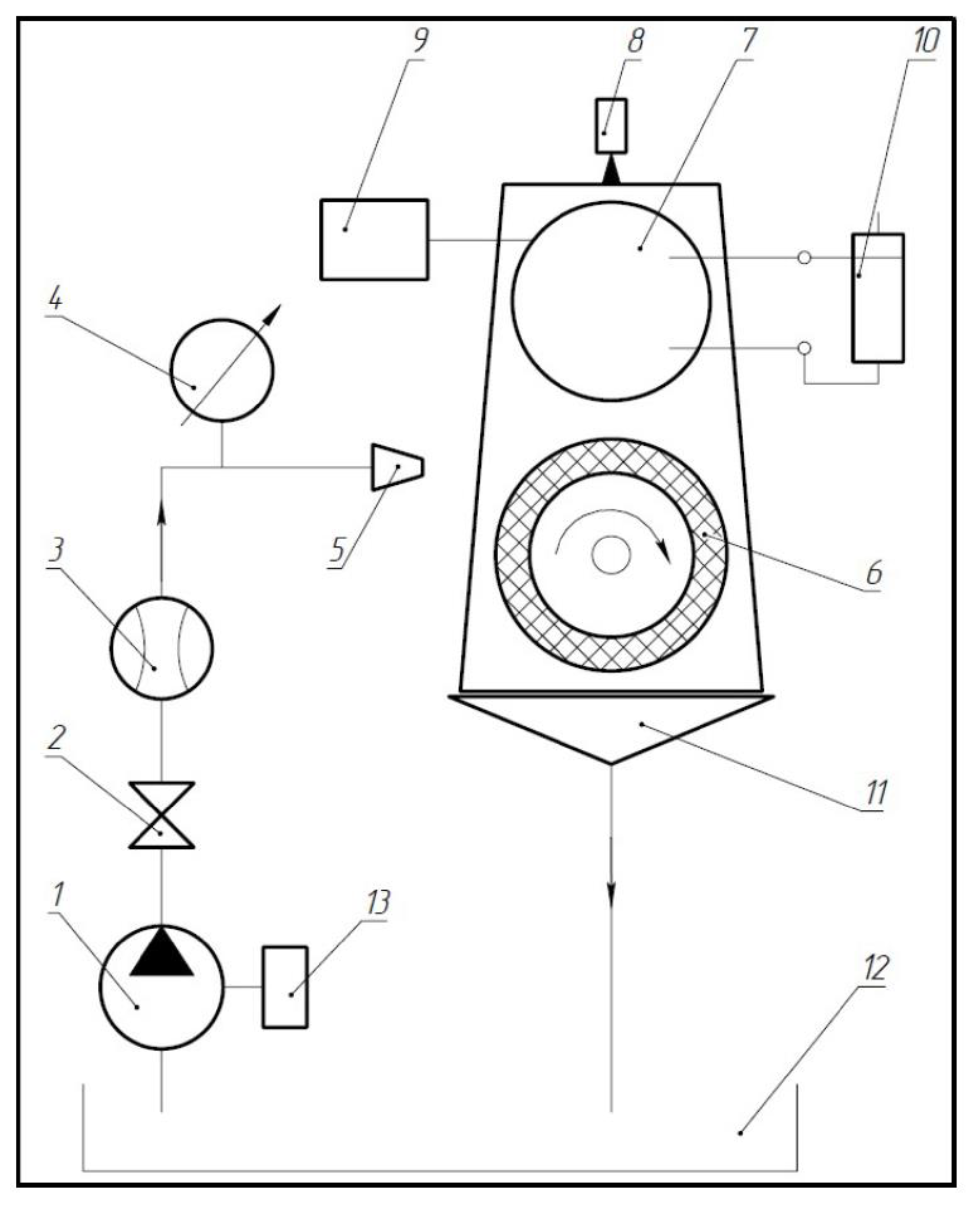
Figure 1. Laboratory bench diagram for testing micro-models of turbines: 1, power pump; 2, valve; 3, flow meter; 4, manometer; 5, nozzle; 6, turbine; 7, generator; 8, tachometer; 9, scales; 10, adjustable resistor; 11, liquid collection device; 12, tank; 13, variable speed drive.
Energies 14 05292 g001
Figure 2. Diagram of laboratory test bench for pump micromodels: 1, frame; 2, tank with working fluid; 3, the test sample; 4, adjustable electric drive; 5, pivoting bearing; 6, load; 7, 8, scales; 9, measuring container; 10, 11, block; 12, cable; 13, delivery line; 14, adjusting valve; 15, 17, pressure gauge; 16, lever.
Energies 14 05292 g002
Figure 3. Micromodel of Euler turbine (rotor version). Source: authors’ development.
Energies 14 05292 g003
Figure 4. Turbine micromodel according to RF patent No. 203,833 (variant). Source: authors’ development.
Energies 14 05292 g004
Figure 5. Variant of the mesh nozzle diaphragm. Source: authors’ development.
Energies 14 05292 g005
Figure 6. Computational scheme of the jet apparatus. Source: authors’ development.
Energies 14 05292 g006
Figure 7. Computational scheme of the jet apparatus (variant with a rotating mixing chamber). Source: authors’ development.
Energies 14 05292 g007
Figure 8. Computer simulation results for the turbine with a central nozzle diaphragm arrangement (Operation mode 1). Source: authors’ development.
Energies 14 05292 g008aEnergies 14 05292 g008b
Figure 9. Computer simulation results for the turbine with a central nozzle diaphragm arrangement (Operation mode 2). Source: authors’ development.
Energies 14 05292 g009
Figure 10. Computer simulation results for the turbine with an external working gas inlet (Operation mode 3). Source: authors’ development.
Energies 14 05292 g010
Figure 11. Computer simulation results for the turbine with an external working gas inlet (Operation mode 4). Source: authors’ development.
Energies 14 05292 g011
Figure 12. Experimental ejector. Source: authors’ development.
Energies 14 05292 g012
Figure 13. Micromodel of the mesh turbine rotor according to RF patent No. 203,833 (variant). Source: authors’ development.
Energies 14 05292 g013
Figure 14. 3D model of the hybrid turbopump (variant). Source: authors’ development.
Energies 14 05292 g014
Figure 15. Guiding device prototype of the new hybrid labyrinth pump. Source: authors’ development.
Energies 14 05292 g015
Figure 16. Impeller prototype of the new hybrid labyrinth pump. Source: authors’ development.
Energies 14 05292 g016
Figure 17. Dependence of pump head coefficient (K) on pump output for different pump versions. Source: authors’ development.
Energies 14 05292 g017aEnergies 14 05292 g017b
Figure 18. Calculated and experimental characteristics of a pump stage with an open impeller. Source: authors’ development.
Energies 14 05292 g018aEnergies 14 05292 g018b
Figure 19. Interrelation between pump output and axial force acting on the open impeller at different viscosity values of the pumped liquid. Source: authors’ development.
Energies 14 05292 g019
Publisher’s Note: MDPI stays neutral with regard to jurisdictional claims in published maps and institutional affiliations.