
Numerical Analysis of Natural Convection Driven Flow of a Non-Newtonian Power-Law Fluid in a Trapezoidal Enclosure with a U-Shaped Constructal


Abstract
:1. Introduction
2. Mathematical Modelling
3. Numerical Computation
4. Results and Discussion
5. Conclusions
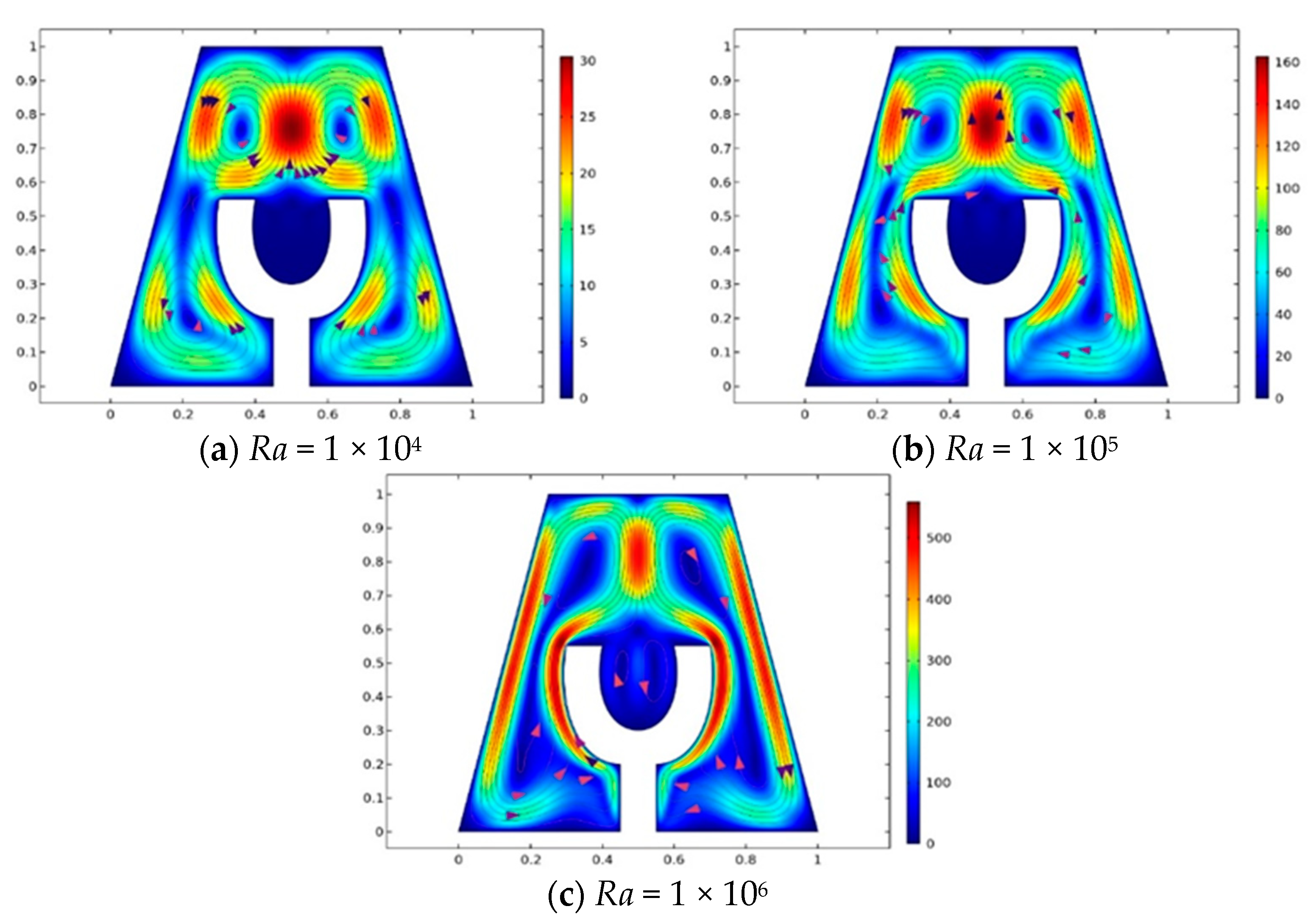
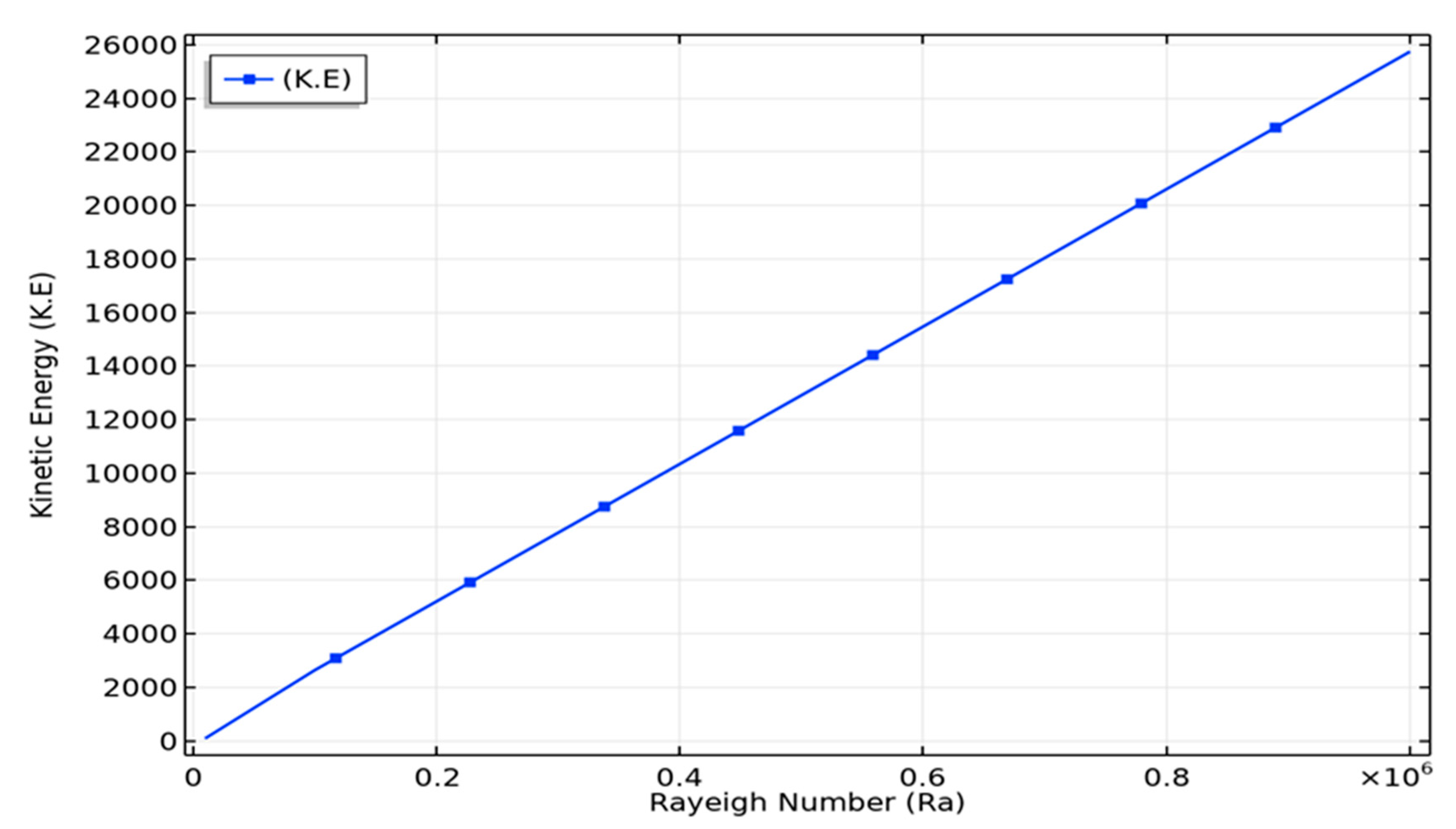
- Increasing magnitude of results in increased magnitude of kinetic energy, i.e., energy associated with the motion of the fluid particles.
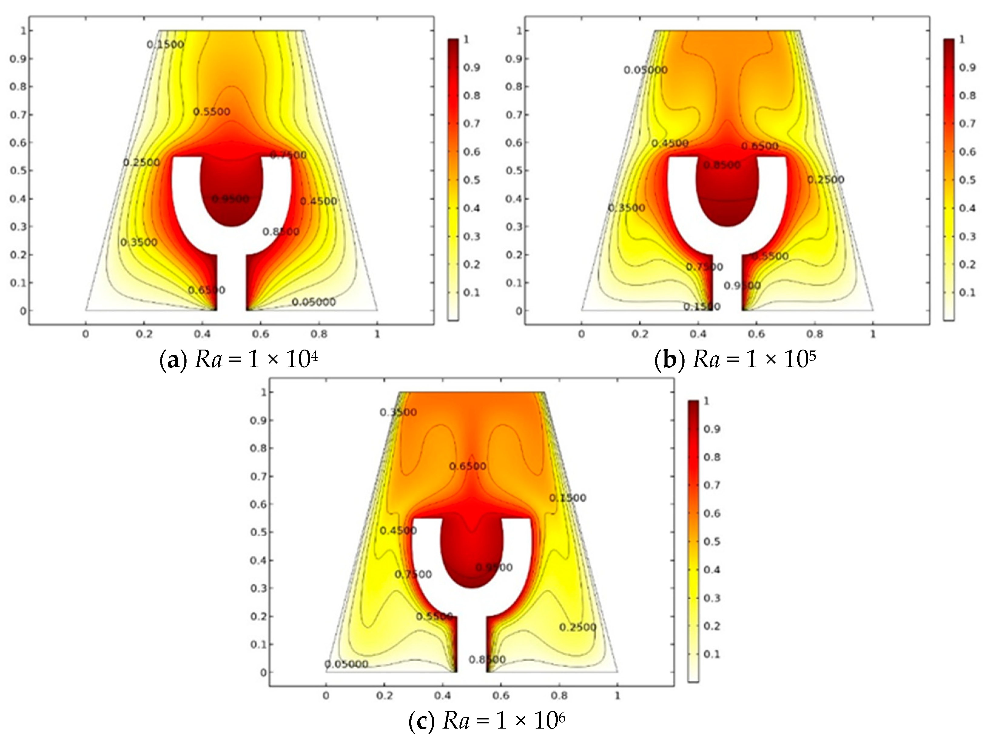
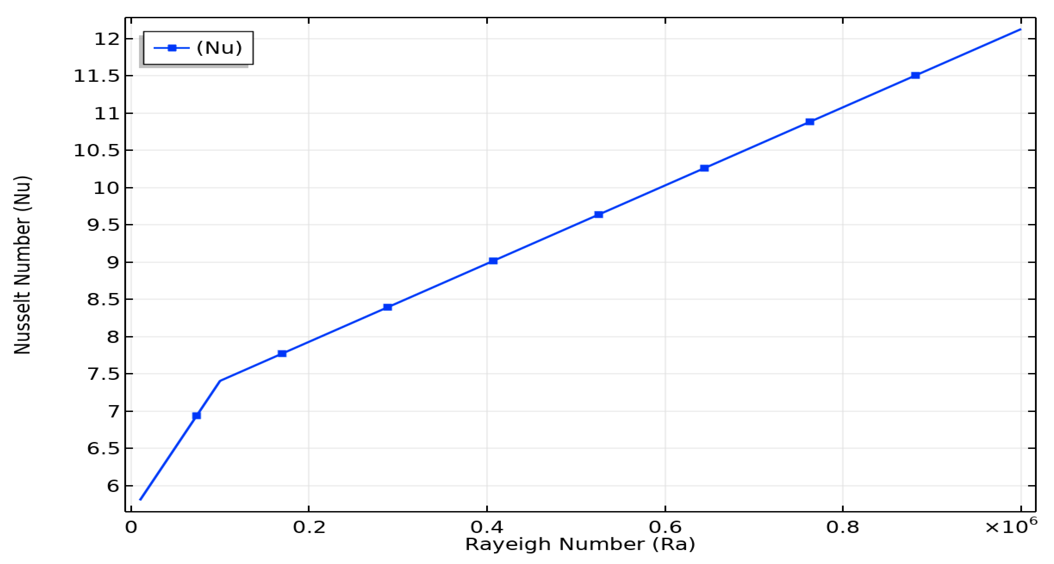
- The heat flux increases with the increase in Rayleigh number.
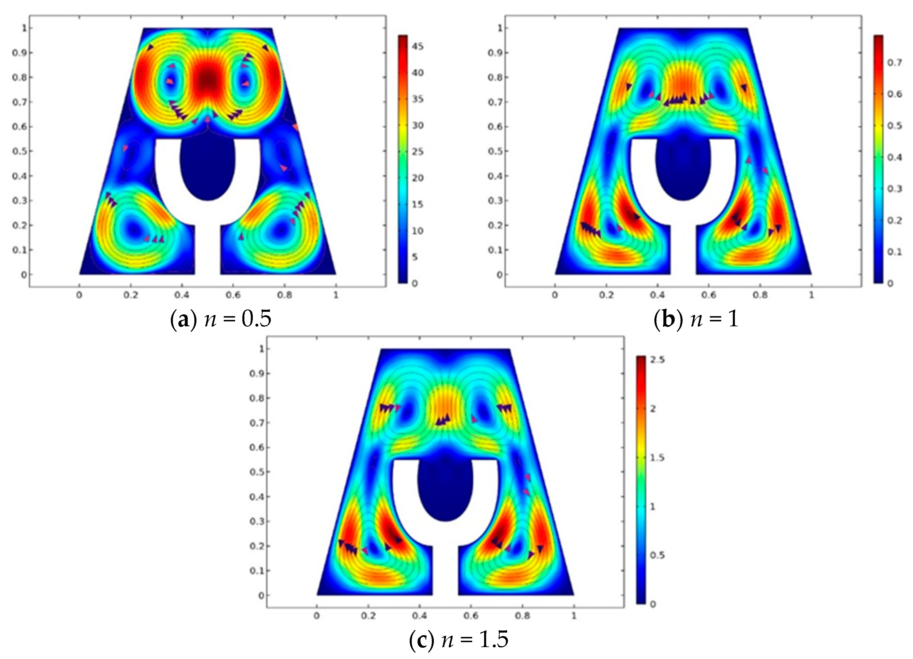
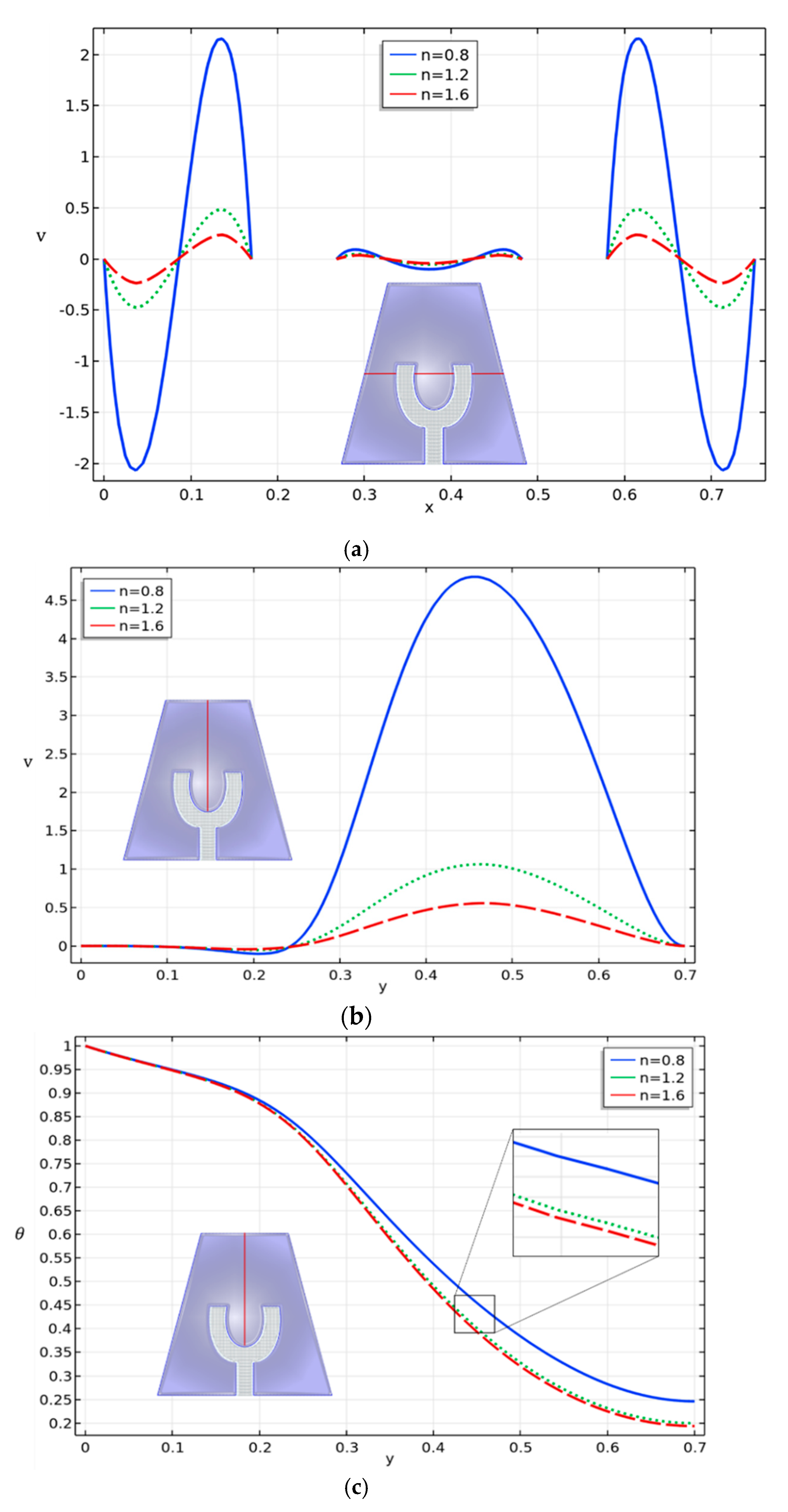
- The fluid flow circulations are greatly affected by the increase in and . As the degree of increases, velocity increases, whereas opposite behavior is seen for increasing values of .
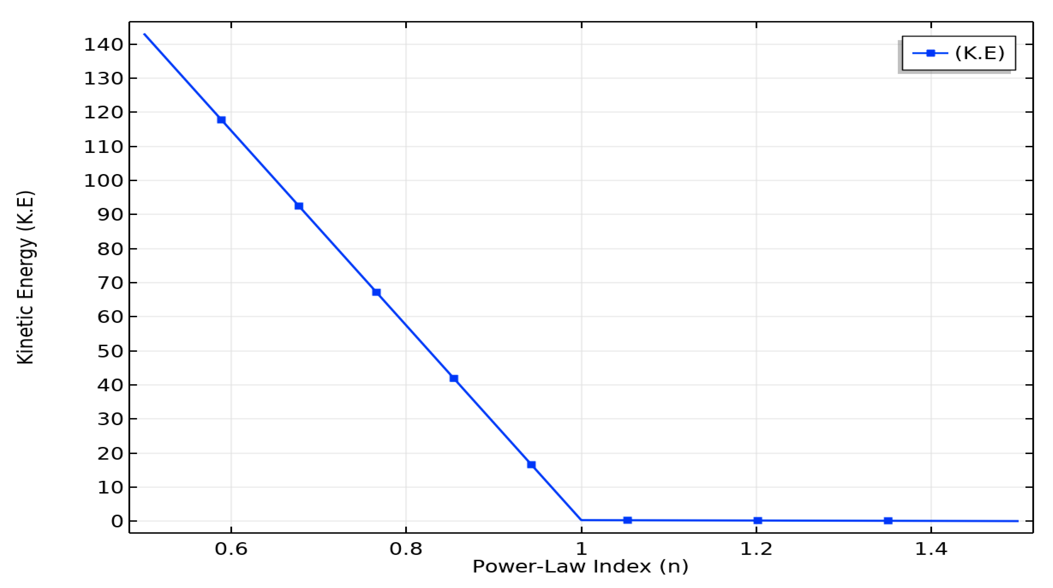
- The kinetic energy for the shear-thinning case of the fluid decreases, whereas an abrupt increase is seen as the magnitude of the power-law index increments.
- Table graphs for the kinetic energy and Nusselt number are illustrated against the Rayleigh number and power-law index.
Author Contributions
Funding
Institutional Review Board Statement
Informed Consent Statement
Data Availability Statement
Conflicts of Interest
Nomenclature
| Velocity components | |
| Fluid density | |
| Fluid pressure | |
| Gravity | |
| Thermal expansion coefficient | |
| Fluid temperature | |
| Power-law index | |
| The temperature of the cold wall | |
| Ra | Rayleigh number |
| Pr | Prandtl number |
| K.E. | Kinetic energy |
References
- Alebrahim, A.; Bejan, A. Constructal trees of circular fins for conductive and convective heat transfer. Int. J. Heat Mass Transfer 1999, 42, 3585–3597. [Google Scholar] [CrossRef]
- Almogbel, M.; Bejan, A. Cylindrical trees of pin fins. Int. J. Heat Mass Transfer 2000, 43, 4285–4297. [Google Scholar] [CrossRef]
- Kraus, A.D.; Aziz, A.; Welty, J.R. Extended Surface Heat Transfer; John-Wiley: New York, NY, USA, 2002. [Google Scholar]
- Lorenzini, G.; Biserni, C.; Isoldi, L.A.; Santos, E.D.D.; Rocha, L.A.O. Constructal design applied to the geometric optimization of Y-shaped cavities embedded in a conducting medium. J. Electron. Packag. 2011, 133, 041008. [Google Scholar] [CrossRef]
- Lorenzini, G.; Rocha, L.A.O. Geometric optimization of TY-shaped cavity according to constructal design. Int. J. Heat Mass Transfer 2009, 52, 4683–4688. [Google Scholar] [CrossRef]
- Abdi, A.; Martin, V.; Chiu, J.N. Numerical investigation of melting in a cavity with vertically oriented fins. Appl. Energy 2019, 235, 1027–1040. [Google Scholar] [CrossRef]
- Bendaraa, A.; Charafi, M.M.; Hasnaoui, A. Numerical study of natural convectionin a differentially heated square cavity filled with nanofluid in the presence of fins attached to walls in different locations. Phys. Fluids 2019, 31, 052003. [Google Scholar] [CrossRef]
- Goodarzi, H.; Akbari, O.A.; Sarafraz, M.M.; Karchegani, M.M.; Safaei, M.R.; Shabani, G.A.S. Numerical simulation of natural convection heat transfer of nanofluid with Cu, MWCNT, and Al2O3 nanoparticles in a cavity with different aspect ratios. J. Therm. Sci. Eng. Appl. 2019, 11, 061020. [Google Scholar] [CrossRef]
- Shi, X.; Khodadadi, J.M. Laminar natural convection heat transfer in a differentially heated square cavity due to a thin fin on the hot wall. J. Heat Transfer 2003, 125, 624–634. [Google Scholar] [CrossRef]
- Horbach, C.d.S.; Santos, E.D.d.; Isoldi, L.A.; Rocha, L.A.O. Constructal design of Y-shaped conductive pathways for cooling a heat-generating body. Defect Diffus. Forum 2014, 348, 245–260. [Google Scholar] [CrossRef]
- Rehman, K.; Kouz, W.A.; Sherif, E.S.; AbdelMalek, Z. Hybrid meshed analysis on rhombus shaped solid material domain (RSSMD) equipped with non-Newtonian liquid stream. J. Sci. Adv. Mater. Devices 2020, 5, 476–486. [Google Scholar] [CrossRef]
- Tavana, M.; Pourmehran, O.; Aghaei, A.; Sangara, J.A. Mofid Gorji-Bandpy, Numerical Analysis of Fluid Flow and Heat Transfer in Microchannels with Various Internal Fins. Int. J. Artif. Intell. Mechatron. 2015, 3, 2320–5121. [Google Scholar]
- Scozia, R.; Frederick, R.L. Natural Convection in Slender Cavities with Multiple Fins Attached on an Active Wall. Numer. Heat Transfer 1991, 20, 127–158. [Google Scholar] [CrossRef]
- Facas, G.N. Natural Convection in a Cavity with Fins Attached to Both Vertical Walls. J. Thermophys. Heat Transfer 1993, 7, 555–560. [Google Scholar] [CrossRef]
- Nag, A.; Sarkar, A.; Sastri, V.M.K. Natural Convection in a Differentially Heated Square Cavity with a Horizontal Partition Plate on the Hot Wall. Comput. Methods Appl. Mech. Eng. 1993, 110, 143–156. [Google Scholar] [CrossRef]
- Ozoe, H.; Churchill, S.W. Hydrodynamic stability and natural convection in Ostwald–de Waele and Ellis fluids: The development of a numerical solution. AIChE J. 1972, 18, 1196–1207. [Google Scholar] [CrossRef]
- Kaddiri, M.; Naïmi, M.; Raji, A.; Hasnaoui, M. Rayleigh Benard convection of non-Newtonian power-law fluids with temperature-dependent viscosity. ISRN Thermodyn. 2012, 2012, 614712. [Google Scholar] [CrossRef] [Green Version]
- Kim, G.B.; Hyun, J.M.; Kwak, H.S. Transient buoyant convection of a power-law non-Newtonian fluid in an enclosure. Int. J. Heat Mass Transf. 2003, 46, 3605–3617. [Google Scholar] [CrossRef]
- Lamsaadi, M.; Naïmi, M.; Hasnaoui, M. Natural convection heat transfer in shallow horizontal rectangular enclosures uniformly heated from the side and filled with non-Newtonian power law fluids. Energy Convers. Manag. 2006, 47, 2535–2551. [Google Scholar] [CrossRef]
- Lamsaadi, M.; Naïmi, M.; Hasnaoui, M.; Mamou, M. Natural convection in a tilted rectangularslot containing nonNewtonian power-law fluids and subject to a longitudinal thermal gradient. Numer. Heat Transf. Part A Appl. Int. J. Comput. Methodol. 2006, 50, 561–583. [Google Scholar] [CrossRef]
- Turan, O.; Sachdeva, A.; Chakraborty, N.; Poole, R.J. Laminar natural convection of power-law fluids in a square enclosure with differentially heated side walls subjected to constant temperatures. J. Non-Newton. Fluid Mech. 2011, 166, 1049–1063. [Google Scholar] [CrossRef]
- Ternik, P.; Rudolf, R. Laminar natural convection of non-Newtonian nanofluid in a square enclosure whit differentially heated side walls. Int. J. Simul. Modeling 2013, 12, 5–16. [Google Scholar] [CrossRef]
- Turan, O.; Sachdeva, A.; Poole, R.J.; Chakraborty, N. Aspect ratio and boundary conditions effects on laminar natural convection of power-law fluids in a rectangular enclosure with differentially heated side walls. Int. J. Heat Mass Transf. 2013, 60, 722–738. [Google Scholar] [CrossRef]
- Ternik, P.; Buchmeister, J. Buoyacy-induced flow and heat transfer of power law fluids in a side heated square cavity. Int. J. Simul. Modeling 2015, 14, 238–249. [Google Scholar] [CrossRef]
- Alloui, Z.; Vasseur, P. Natural convection of Carreau–Yasuda non-Newtonian fluids in a vertical cavity heated from the sides. Int. J. Heat Mass Transf. 2015, 84, 912–924. [Google Scholar] [CrossRef]
- Ouertatani, N.; Cheikh, N.B.; Beya, B.B.; Lili, T. Numerical simulation of two-dimensional Rayleigh–Bénard convection in an enclosure. Comptes Rendus Mécanique 2008, 336, 464–470. [Google Scholar] [CrossRef]
- Kumari, M.; Pop, I.; Takhar, H.S. Free-convection boundary-layer flow of a non-Newtonian fluid along a vertical wavy surface. Int. J. Heat Fluid Flow 1997, 18, 625–631. [Google Scholar] [CrossRef]
- Lewandowski, W.M.; Radziemska, E.; Buzuk, M.; Bieszk, H. Free convection heat transfer and fluid flow above horizontal rectangular plates. Appl. Energy 2000, 66, 177–197. [Google Scholar] [CrossRef]
- Jordán, J.Z. Numerical study of an unsteady free convective magnetohydrodynamic flow of a dissipative fluid along a vertical plate subject to a constant heat flux. Int. J. Eng. Sci. 2006, 44, 1380–1393. [Google Scholar] [CrossRef]
- Jha, B.K.; Ajibade, A.O. Free convective flow of heat generating/absorbing fluid between vertical porous plates with periodic heat input. Int. Commun. Heat Mass Tran. 2009, 36, 624–631. [Google Scholar] [CrossRef]
- Jha, B.K.; Samaila, A.K.; Ajibade, A.O. Transient free-convective flow of reactive viscous fluid in vertical tube. Math. Comput. Model. 2011, 54, 2880–2888. [Google Scholar] [CrossRef]
- Ahmed, J.; Mahmood, T.; Iqbal, Z.; Shahzad, A.; Ali, R. Axisymmetric flow and heat transfer over an unsteady stretching sheet in power law fluid. J. Mol. Liq. 2016, 221, 386–393. [Google Scholar] [CrossRef]
- Al-Kouz, W.; Alshare, A.; Alkhalidi, A.; Kiwan, S. Two dimensional analysis of low pressure flows in the annulus region between two concentric cylinders. Springer Plus 2016, 5, 529. [Google Scholar] [CrossRef] [Green Version]
- Shahzad, A.; Ali, R.; Hussain, M.; Kamran, M. Unsteady axisymmetric flow and heat transfer over time-dependent radially stretching sheet. Alexandria Eng. J. 2017, 56, 35–41. [Google Scholar] [CrossRef] [Green Version]
- Ahmed, J.; Shahzad, A.; Begum, A.; Ali, R.; Siddiqui, N. Effects of inclined Lorentz forces on boundary layer flow of Sisko fluid over a radially stretching sheet with radiative heat transfer. J. Braz. Soc. Mech. Sci. Eng. 2017, 39, 3039–3050. [Google Scholar] [CrossRef]
- Mishra, S.R.; Khan, I.; Al-Mdallal, Q.M.; Asifa, T. Free convective micropolar fluid flow and heat transfer over a shrinking sheet with heat source. Case Stud. Therm. Eng. 2018, 11, 113–119. [Google Scholar] [CrossRef]
- Khan, M.; Salahuddin, T.; Malik, M.Y.; Khan, F.; Hussain, A. Variable diffusion and conductivity change in 3d rotating Williamson fluid flow along with magnetic field and activation energy. Int. J. Numer. Methods Heat Fluid Flow 2019, 30, 2467–2484. [Google Scholar] [CrossRef] [Green Version]
- Sakinder, S.; Salahuddin, T.; Fahad, S.; Al-Mubaddel, S.; Alam, M.M.; Ahmad, I. Influence of entropy generation on hybrid nanoparticles near the lower region of solid sphere. Case Stud. Therm. Eng. 2021, 26, 101–123. [Google Scholar] [CrossRef]
- Lin, P.; Ghaffari, A. Steady flow and heat transfer of the power-law fluid between two stretchable rotating disks with non-uniform heat source/sink. J. Therm. Anal. Calorim. 2020. [Google Scholar] [CrossRef]
- Lin, P.; Gaffari, A. Mustafa, A theoretical analysis of steady three-dimensional flow and heat transfer of Power-Law nanofluid over a stretchable rotating disk filled with gyrotactic microorganisms. Phys. Scr. 2020, 96, 015008. [Google Scholar]
- Ghaffari, A.; Kausar, S. Numerical solution of the partial differential equations that model the steady three-dimensional flow and heat transfer of Carreau fluid between two stretchable rotatory disks. Numer. Methods Partial. Differ. Equ. 2020. [Google Scholar] [CrossRef]
- Khan, M.I.; Shah, F.; Khan, S.U.; Ghaffari, A.; Chu, Y.M. Heat and mass transfer analysis for bioconvective flow of Eyring Powell nanofluid over a Riga surface with nonlinear thermal features. Numer. Methods Partial. Differ. Equ. 2020. [Google Scholar] [CrossRef]
- Usman, W.; Khan, I.; Badruddin, A.; Gaffari, A.; Ali, H.M. Heat transfer in steady slip flow of tangent hyperbolic fluid over the lubricated surface of a stretchable rotatory disk. Case Stud. Therm. Eng. 2021, 24, 100825. [Google Scholar] [CrossRef]
- Ahmad, H.; Alam, N.; Omri, M. New computational results for a prototype of an excitable system. Results Phys. 2021, 11, 104666. [Google Scholar] [CrossRef]
- Goodarzi, M.; Safaei, M.R.; Karimipour, A.; Hooman, K.; Dahari, M.; Kazi, S.N.; Sadeghinezhad, E. Comparison of the Finite Volume and Lattice Boltzmann Methods for Solving Natural Convection Heat Transfer Problems inside Cavities and Enclosures. In Abstract and Applied Analysis; Hindawi: London, UK, 2014. [Google Scholar] [CrossRef]
- Pordanjani, A.H.; Aghakhani, S.; Karimipour, A.; Afrand, M.; Goodarzi, M. Investigation of free convection heat transfer and entropy generation of nanofluid flow inside a cavity affected by magnetic field and thermal radiation. J. Therm. Anal. Calorim. 2019, 137, 997–1019. [Google Scholar] [CrossRef]
- Yousefzadeh, S.; Rajabi, H.; Ghajari, N.; Sarafraz, M.M.; Akbari, O.M.; Goodarzi, M. Numerical investigation of mixed convection heat transfer behavior of nanofuid in a cavity with diferent heat transfer areas. J. Therm. Anal. Calorim. 2020, 140, 2779–2803. [Google Scholar] [CrossRef]
- Goodarzi, M.; D’Orazio, A.; Keshavarzi, A.; Mousavi, S.; Karimipour, A. Develop the nano scale method of lattice Boltzmann to predict the fluid flow and heat transfer of air in the inclined lid driven cavity with a large heat source inside, Two case studies: Pure natural convection & mixed convection. Phys. A Stat. Mech. Appl. 2018, 509, 210–233. [Google Scholar] [CrossRef]
- Aghaei, A.; Sheikhzadeh, G.A.; Goodarzi, M.; Hasani, H.; Damirchi, H.; Afrand, M. Effect of horizontal and vertical elliptic baffles inside an enclosure on the mixed convection of a MWCNTs-water nanofluid and its entropy generation. Eur. Phys. J. Plus 2018, 133, 486. [Google Scholar] [CrossRef]
- Goodarzi, M.; Safaei, M.R.; Oztop, H.F.; Karimipour, A.; Sadeghinezhad, E.; Dahari, M.; Kazi, S.N.; Jomhari, N. Numerical Study of Entropy Generation due to Coupled Laminar and Turbulent Mixed Convection and Thermal Radiation in an Enclosure Filled with a Semitransparent Medium. Sci. World J. 2014. [Google Scholar] [CrossRef]
- Rasool, G.; Khan, W.A.; Bilal, S.M.; Khan, I. MHD squeezed Darcy–Forchheimer nanofluid flow between two h–distance apart horizontal plates. Open Phys. 2020, 18, 1100–1107. [Google Scholar] [CrossRef]
- Rozati, S.A.; Montazerifar, F.; Akbari, O.A.; Hoseinzadeh, S.; Nikkhah, V.; Marzban, A.; Abdolvand, H.; Goodarzi, M. Natural convection heat transfer of water/Ag nanofluid inside an elliptical enclosure with different attack angles. Math. Methods Appl. Sci. 2020. [Google Scholar] [CrossRef]
- Raisi, A. Natural Convection of Non-Newtonian Fluids in a Square Cavity with a Localized Heat Source. Stroj. Vestn. J. Mech. Eng. 2016, 62, 10. [Google Scholar] [CrossRef]

| Refinement Level (R.L) | Number of Triangles | Number of Quads. | Number of Elements | Degree of Freedom |
|---|---|---|---|---|
| R.L (1) | 296 | 112 | 408 | 1172 |
| R.L (2) | 479 | 158 | 637 | 1768 |
| R.L (3) | 736 | 208 | 944 | 2532 |
| R.L (4) | 1331 | 306 | 1637 | 4212 |
| R.L (5) | 1973 | 378 | 2351 | 5856 |
| R.L (6) | 3088 | 472 | 3560 | 8556 |
| R.L (7) | 8507 | 958 | 9465 | 21,824 |
| R.L (8) | 22,901 | 1822 | 24,723 | 54,932 |
| R.L (9) | 27,407 | 1822 | 29,229 | 63,944 |
| Rayleigh Number | Kinetic Energy (K.E) | |
|---|---|---|
| 10,000 | 5.8026 | 89.774 |
| 1.0000 × 10⁵ | 7.4054 | 2637.4 |
| 1.0000 × 10⁶ | 12.129 | 25,737 |
| Power-Law Index | Kinetic Energy (K.E) |
|---|---|
| 0.5 | 206.28 |
| 1 | 0.33140 |
| 1.5 | 0.038054 |
Publisher’s Note: MDPI stays neutral with regard to jurisdictional claims in published maps and institutional affiliations. |
© 2021 by the authors. Licensee MDPI, Basel, Switzerland. This article is an open access article distributed under the terms and conditions of the Creative Commons Attribution (CC BY) license (https://creativecommons.org/licenses/by/4.0/).
Share and Cite
Bilal, S.; Rehman, M.; Noeiaghdam, S.; Ahmad, H.; Akgül, A. Numerical Analysis of Natural Convection Driven Flow of a Non-Newtonian Power-Law Fluid in a Trapezoidal Enclosure with a U-Shaped Constructal. Energies 2021, 14, 5355. https://doi.org/10.3390/en14175355
Bilal S, Rehman M, Noeiaghdam S, Ahmad H, Akgül A. Numerical Analysis of Natural Convection Driven Flow of a Non-Newtonian Power-Law Fluid in a Trapezoidal Enclosure with a U-Shaped Constructal. Energies. 2021; 14(17):5355. https://doi.org/10.3390/en14175355
Chicago/Turabian StyleBilal, Sardar, Maryam Rehman, Samad Noeiaghdam, Hijaz Ahmad, and Ali Akgül. 2021. "Numerical Analysis of Natural Convection Driven Flow of a Non-Newtonian Power-Law Fluid in a Trapezoidal Enclosure with a U-Shaped Constructal" Energies 14, no. 17: 5355. https://doi.org/10.3390/en14175355
APA StyleBilal, S., Rehman, M., Noeiaghdam, S., Ahmad, H., & Akgül, A. (2021). Numerical Analysis of Natural Convection Driven Flow of a Non-Newtonian Power-Law Fluid in a Trapezoidal Enclosure with a U-Shaped Constructal. Energies, 14(17), 5355. https://doi.org/10.3390/en14175355