Abstract
The paper is devoted to the analysis of the operating cycle of a high-pressure injection pump used in common rail systems. The investigation is based on experimental activities, and it is carried out in a novel pump set-up that allows measurements of the instantaneous pressure in the piston working chamber. A single plunger pump has been equipped with a piezo-resistive pressure transducer which allows for the measurement of the pressure signal during pump operation on a test rig. The paper describes the experimental set-up, the modified injection pump equipped with the pressure transducer, and the experimental tests carried out. Main results obtained using a standard commercial diesel fuel are discussed at first; secondly, the focus moves on to the use of an alternative fuel (biodiesel) whose features in terms of bulk modulus, viscosity, and density significantly differ from the reference fuel. Based on the characteristics of the pump operating cycle, the fuel suction and delivery processes are analyzed, pointing out how the used fuel type is reflected on them. The investigations are aimed at describing the operating characteristics of the pump, focusing the attention on those features playing a fundamental role on the global efficiency of the pump. The amplitudes of the pump-work phases, the ranges of pressure fluctuations, and the pressure-rise rates are quantified and reported, providing crucial indications for lumped parameter modeling and design activities in the field of current generation high-pressure injection pumps.
1. Introduction
Diesel engine plays a fundamental role in a variety of applications; its combustion process allows for the adoption of high volumetric compression ratios, leading to high thermodynamic efficiency and low CO2 emissions [1].
Due to the strong need to reduce CO2 emissions, the overall efficiency of the engine [2,3] and the use of alternative fuels (renewable or synthetic) assume higher and higher importance in research activities [4,5,6].
On the use of alternative fuels, the literature is rich; many contributions are devoted to investigating their influence on spray formation processes [7,8,9], on combustion [4,10], on pollutant formation, emission, and performance [7,8,9,11], on wear and components’ life [12,13], and on after-treatment systems [14].
Several other research efforts are devoted at improving the overall efficiency of the engine. Some of them focus on reducing friction losses (cylinder-piston pair, piston rings, bearings, and lubrication) [15,16,17], on engine induction efficiency [18], on reducing losses related to heat exchange during combustion-expansion phases [19], and on the energy recovery at the exhaust [20].
Keeping in mind the research lines mentioned above, it is useful to regard the injection system as a mechanical-hydraulic ancillary operating on fuel. Plainly, the overall performance of the engine reflects the fuel properties, through at least two factors in mutual dependence: on the one hand, the influence on combustion and on the other hand, the influence on the efficiency of injection system, requiring engine torque to be operated.
Referring to common rail high-pressure systems, a considerable fraction of engine power is required to drive the pump. In [21] it is well highlighted that even a limited increase in pump efficiency, given the high power involved, can represent a significant contribution. Pump efficiency depends significantly both on the shaft speed and on the injection pressure. Thus, the overall efficiency of diesel engine depends not only on the absolute performance of the pump but also on its managing (in relation to the other components of the injection system).
From the energy viewpoint, whatever is the level of injection pressure, the common rail system is penalized by the excess fluid laminated by the pressure control valve. Therefore, the sizing of the pump for a given engine and for a given application should undergo careful consideration.
It is now evident that the exhaustive characterization (and modeling) of pump performance is the key element for an efficient management of the injection system, both for traditional and alternative fluids.
The scientific literature on high-pressure diesel injection pumps covers many topics, typically encountered when high-pressure hydraulic machines are investigated.
About pump structure, tribology, and noise, reference [22] deals with the tribological aspects of the piston-cylinder pair, taking the characteristics of the contact surfaces into account. In [23,24], the effects of plunger micro-motion (offset and inclination) on pump operation are investigated by modeling. Reference [24] reports the types of wear encountered in CR high-pressure pumps, highlighting the effects on their functionality. In [25,26], the role of wear in pump noise emission is analyzed, pointing out that the opening of the pump delivery valve is the greatest contributor to noise emission. In [27], the possibility to reduce the gap between piston and cylinder is discussed and a hollow layout of the piston is introduced.
The role of pump efficiency on the injection system management has been recently highlighted in [28]. The dynamical performance of the high-pressure pump and the impact of the rail pressure control strategy on instantaneous torque, energy saving, and flow rate ripple are thoroughly investigated in [29].
The fundamental investigation on CR pump performance is reported in [21], where the results of a theoretical-experimental activity aimed at characterizing the behavior of injection radial pumps are reported; it is worthy to be pointed out that pump performance is expressed by volumetric efficiency and torque efficiency. These parameters are the fundamental information to define the proper management of the injection system. The results reported in [21] refer to the radial pumps, whose layout is based on three pumping elements arranged radially, displaced by 120 degrees.
The configuration of the current generation pumps is instead based on a single pumping element that performs two work cycles for each shaft revolution; pump shaft speed is also modified, being the same as that of engine crank shaft.
Experimental investigations on single piston pumps and results on performance in terms of volumetric and torque efficiency have not yet been reported in the literature. Aimed at filling this gap, the authors have recently devoted a research activity in this field to investigating a single piston pump; volumetric and torque efficiencies in a wide operation range of the pump are measured both with standard diesel fluid and with diesel-biodiesel blends [30].
On one side, volumetric and torque efficiency of the pump certainly provide the crucial information discussed above. On the other hand, especially when alternative fluids (e.g., biodiesel and its blends) are considered, it is fundamental to investigate the pump work cycle by experiments.
The instantaneous measurement of pressure in piston working chamber allows one to identify suction, compression-expansion, and delivery phases of the fluid. The effects of fuel properties become appreciable on each pumping phase and comparative analyses are straightforward. Such information is also crucial to validate pump models that take the cylinder-piston pair into account, where leakages, deformations, and other non-idealities affect pump operation and its efficiency.
Although this experimental approach is notorious in the field of volumetric machines, it lacks in the literature on CR injection pumps. The contributions present in the literature, such as [21,31,32] are limited to the modeling activities. In addition, reference [33], that deals with an in-depth modeling activity of a three-piston radial pump, reports just a single indicator diagram, communicated by the pump manufacturer.
The severe stresses on pressure transducers and the limited accessibility for their installation on pump bodies represent critical issues for the measurements in piston working chamber. Nevertheless, this article reveals the suitability of such experimental approach on the current-production CR pumps. Once the details of the method and the experimental set-up are presented and discussed, a single-piston CR pump is characterized through the analysis of its pumping cycle diagrams. After the analysis is completed for the standard diesel fuel, the focus is moved on the use of alternative fuels (pure biodiesel B100 and biodiesel/diesel blends B20 and B40), highlighting how the fluids influence the behavior of the pump. The investigations are aimed at describing the operating characteristics of the pump, quantitatively. Among the various aspects of interest, here the attention is focused on those features playing a fundamental role on the global efficiency of the pump. Thus, the amplitudes of the pump work phases, the ranges of pressure fluctuations, and the pressure-rise rates are quantified and reported, providing crucial information in the field of current generation high-pressure injection pumps.
2. Materials and Methods
2.1. Experimental Set-Up
The experimental activities are conducted in the Injection Systems Laboratory at Roma TRE University. The investigated injection pump is widely used in the field of light- and medium-duty diesel engines; the pump shaft typically rotates at the same speed as the engine shaft and completes two cycles at each rotation. These pumps have a single piston operated by a roller-cam couple. The piston is tightly coupled to the cylinder for a considerable contact length (ensuring sealing), but in the working chamber it becomes plunging. The pump model here adopted is built by Bosch and belongs to the CP4.1 family [34]. Table 1 reports the relevant pump specifications.

Table 1.
Injection pump specification.
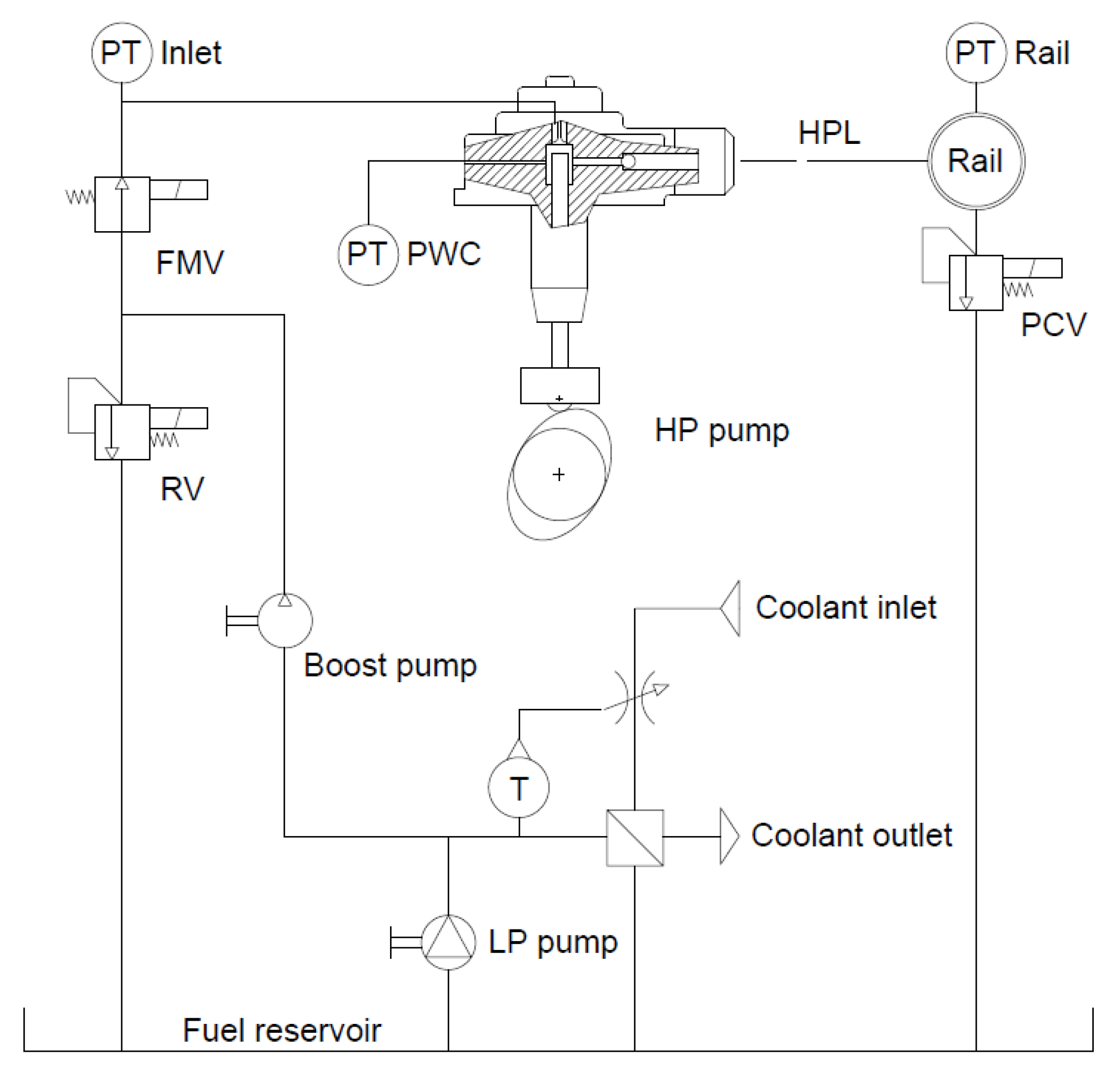
Figure 1 shows the scheme of the high-pressure pump in the test system. Pump shaft speed and rail pressure are imposed as test conditions. The pump speed is independent of the load conditions and is managed by an electric drive, in full vector control. In the rail element (20 cc volume), pressure is regulated under PID logic, through a controller that drives the Pressure Control Valve (PCV). A low-pressure circuit carries out the thermoregulation of the working fluid through a heat exchanger which works in combination with a thermostatic valve set on the coolant side. The volumetric boost pump feeds the High-Pressure (HP) pump; the Relief Valve (RV), housed in the HP pump case, regulates the fuel pressure level upstream of the Flow Control Valve (FMV); in this work, the FMV valve is always fully opened.
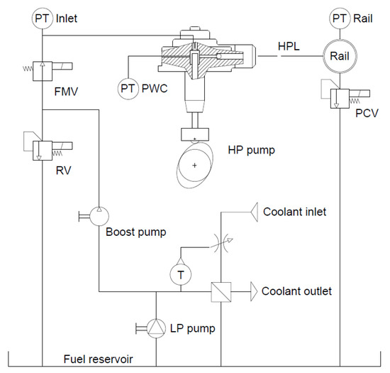
Figure 1.
Schematic of experimental set-up.
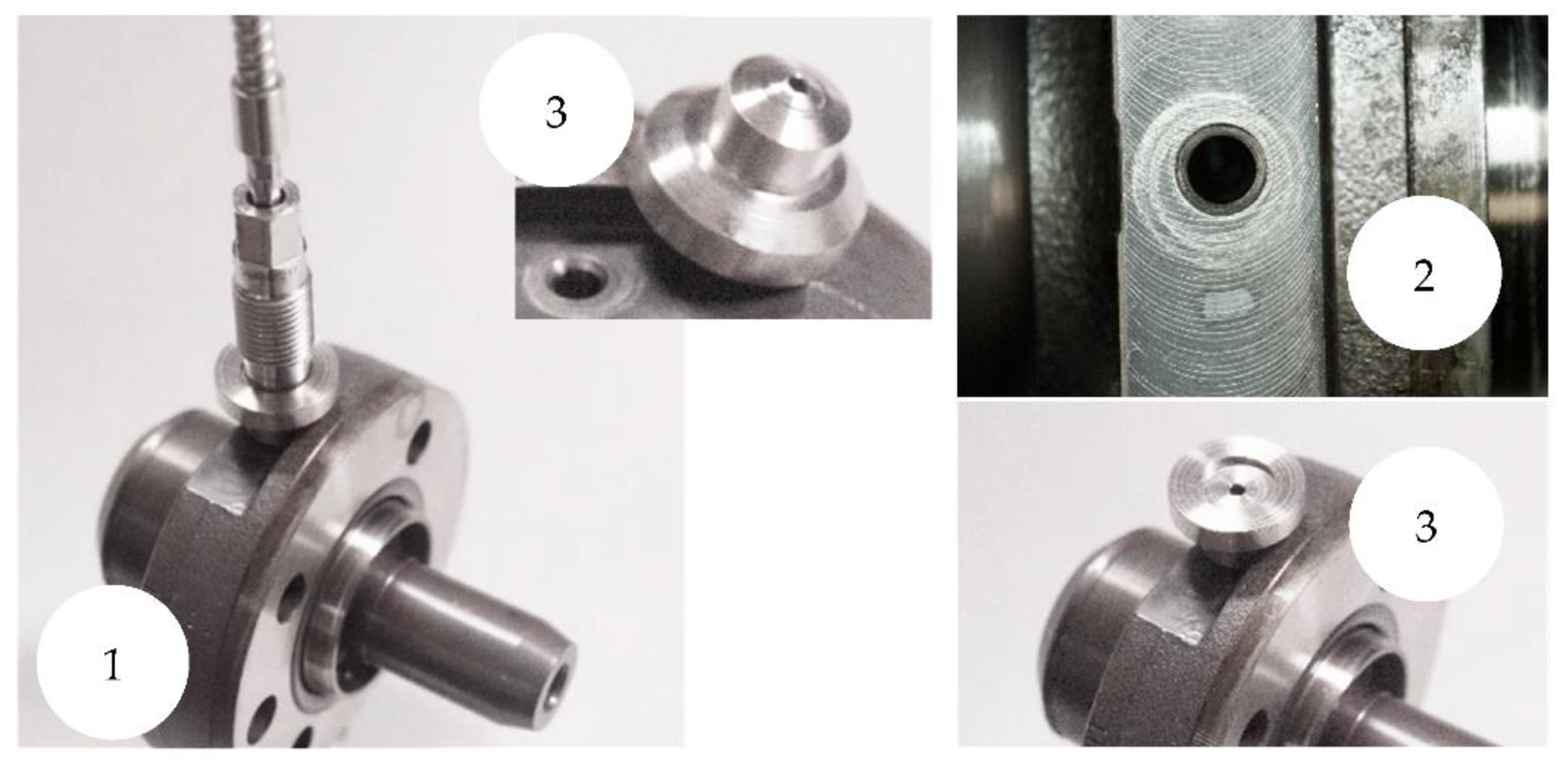
A modification on the pump body allows the instantaneous pressure measurement within the Piston Working Chamber (PWC): a hole, made through the pump body, connects the chamber to the PT-PWC pressure sensor.
Figure 2 shows the pump body (1) provided with the access hole to the working chamber (2). The connection of the transducer to the pump is made through the sealing element (3) which is the interface between the head of the transducer and the access hole. The transducer is screwed onto the pump support (4); the set-up is completed by the annular contrast element (5). From the hydraulic viewpoint, such a modification adds 70 mm3 capacity to the pump dead volume.
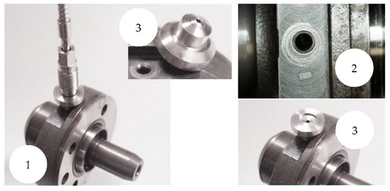
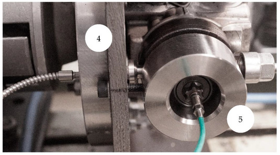
Figure 2.
Injection pump provided with pressure sensor (PT-PWC).
PT-Inlet and PT-Rail sensors detect the pressure respectively upstream of pump inlet valve and in delivery environment (rail), which is connected to the pump through the HPL high-pressure line.
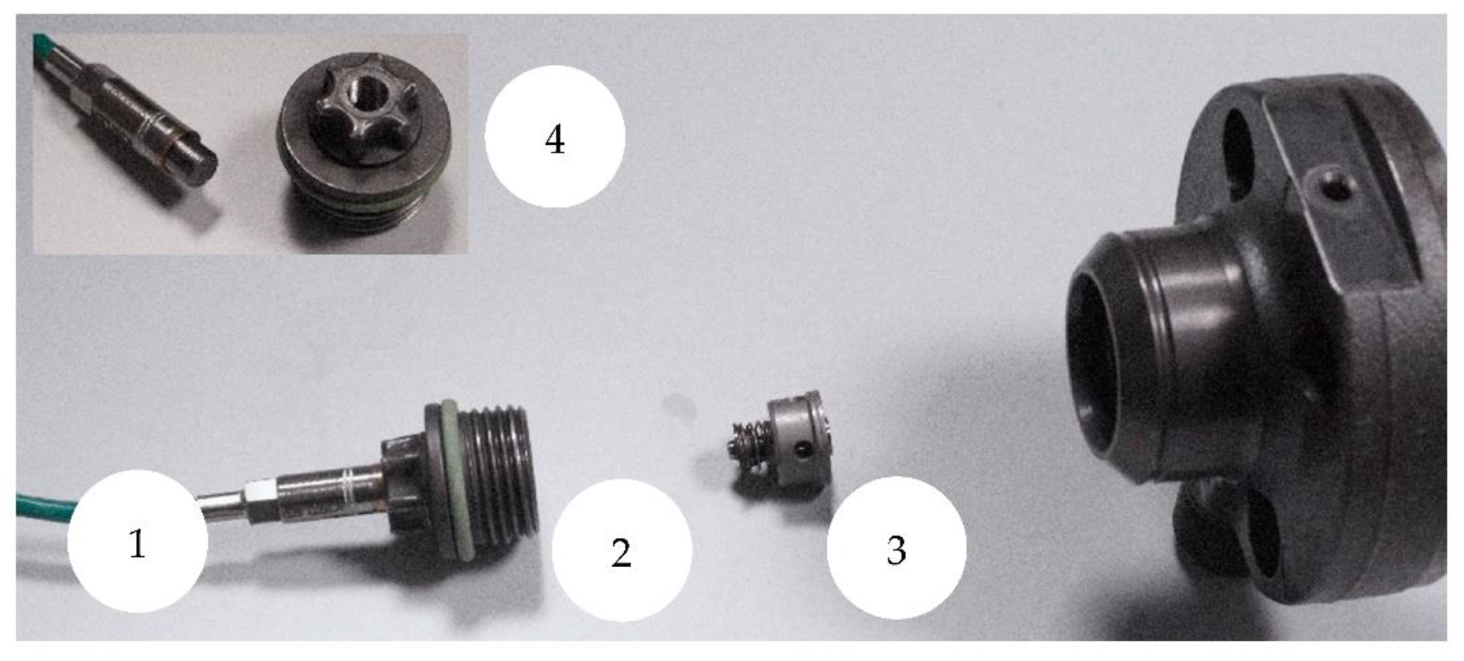
The housing for the PT-Inlet sensor (Figure 3) is made with a minimal pump modification. With reference to Figure 3, PT-Inlet sensor (1) is housed on the head-cover (2), which holds the pump-head provided with the inlet poppet valve (3). Detail (4) shows the sensor and the head-cover disassembled.
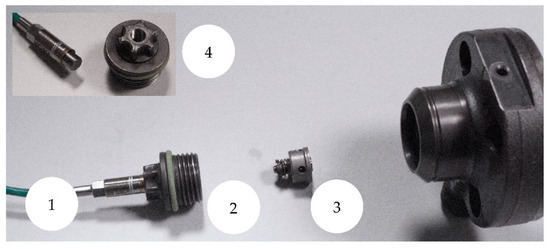
Figure 3.
(1) PT-Inlet pressure sensor; (2) Head-cover provided with PT-Inlet pressure sensor; (3) Pump-head with inlet valve; (4) detail view of disassembled sensor and head-cover.
With reference to Figure 4, PT-Rail sensor (1) is installed on a blind injection pipe connected to the rail.
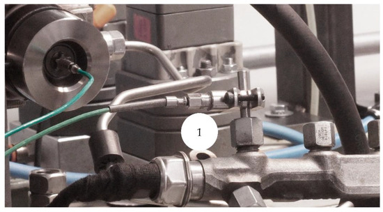
Figure 4.
(1) PT-Rail pressure sensor installed on a blind injection pipe.
A rotary encoder detects the angular position of the pump shaft. Once the cam profile and its phasing are known, the position of the pumping element and the volume of fluid inside the working chamber are calculated. The instrumentation signals are sent to a multi-channel DAQ system and simultaneously acquired. Table 2 reports the features of the instrumentation used.
Table 2.
Instrumentation features.
2.2. Tested Fluids
As mentioned in the introduction section, the pure reference fluid is the commercial premium diesel fuel Diesel+ (D100), compliant to EN 590 regulation.
Due to the known concern on CO2 emission, the alternative tested fluids are represented by a Waste Cooking Oil (WCO) biodiesel (B100) and by its blends (B20 and B40) with diesel fuel. Blends are prepared at 40 °C temperature; B20 blend is intended as 20% biodiesel volume and 80% diesel volume, B40 is intended as 40–60%. The adopted biodiesel is compliant to the EN 14214 regulation, and it is produced by trans-esterification and distillation processes of waste cooking oil. Information about bulk modulus is derived by literature [35], whereas density and viscosity are communicated by the producers of fuels. Table 3 resumes their mechanical specifications.
Table 3.
Specifications of used pure fluids.
2.3. Test Cases
Three rail pressure levels and two pump speeds are considered. Table 4 reports the test conditions that represent six experimental cases for each tested fuel; the considered pressure points are to be intended as representative of low, medium, and high levels of injection pressure; the two speed points represent the condition close to the maximum torque of the engine (1500 RPM) and the typical condition at medium/high load (3000 RPM).
Table 4.
Test conditions.
3. Results and Discussion
3.1. Piston Displacement and Swept Volume
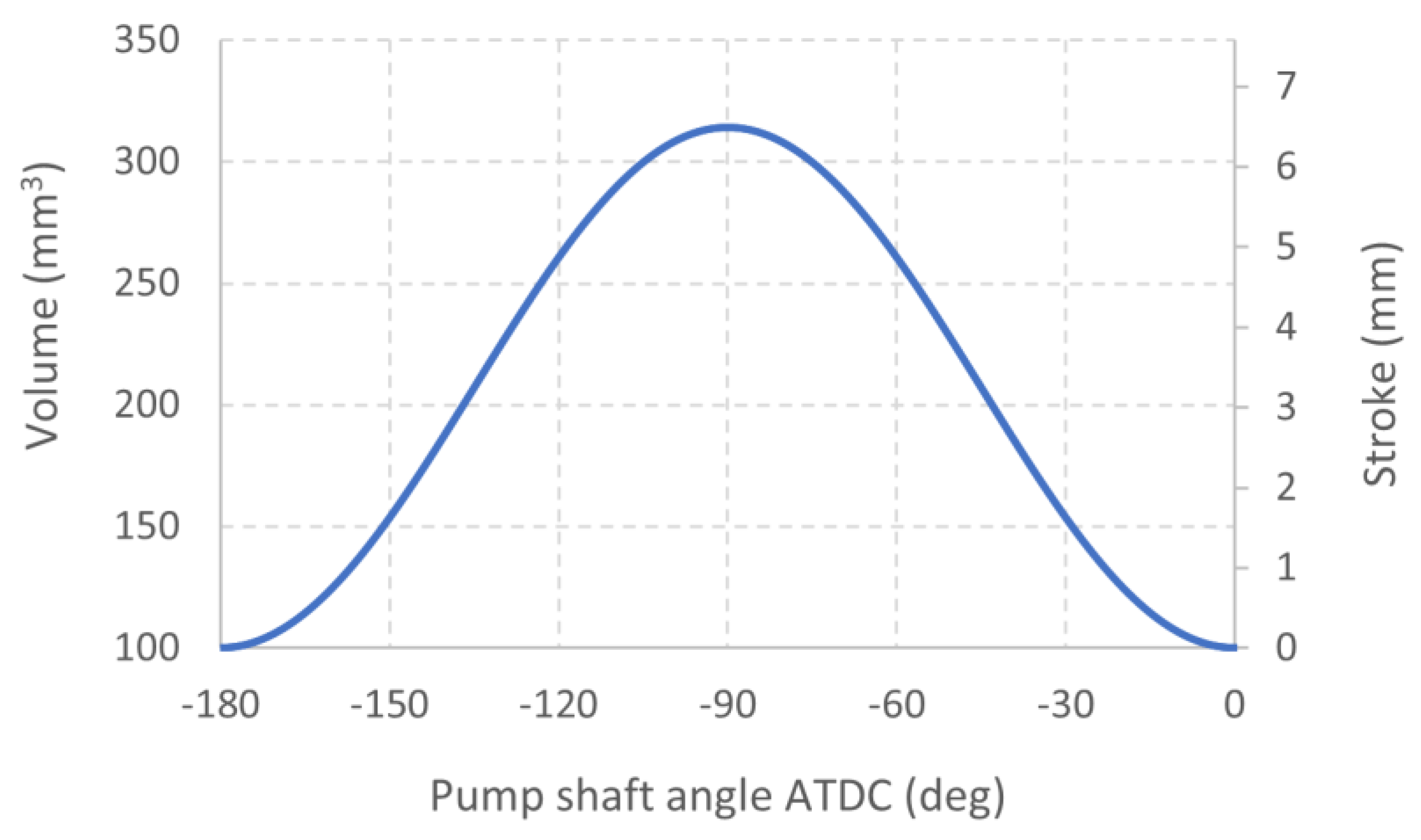
Piston stroke versus pump shaft angle is measured with the help of a digital absolute encoder and a millesimal digital comparator. The piston position with respect to pump shaft angle is acquired at the resolution of one degree. The data obtained are subsequently processed through a cubic interpolation function, the piston diameter is known (6.48 mm), and the volume of PWC is computed. Figure 5 reports the piston stroke and the calculated volume of PWC as a function of pump shaft angle After Top Dead Center (ATDC).
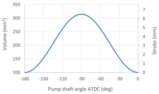
Figure 5.
Piston stroke and volume of PWC vs. pump shaft angle.
3.2. Pump Operation (Reference Fluid)
Figure 6 shows the pressure trend in the PWC as a function of the fluid volume (740 bar, 1500 RPM, D100). The minimum and maximum volumes that appear in the diagram correspond to the volumes of fluid at Top Dead Center (TDC) and Bottom Dead Center BDC), respectively. The diagram reveals the actual behavior of the pump (like a “signature”) by highlighting the operational sub-phases that describe what happens inside the PWC. Since the current article is the first investigation based on PWC pressure measurement reported in the literature, the comparison (and the discussion) with already known experimental data is hereon not possible. Starting from the TDC, the fluid pressure suddenly drops until the opening conditions of the inlet valve are reached. The piston stroke in this sub-phase is needed for the decompression of the liquid. Once the conditions for opening the intake valve are reached (fuel pressure equals the valve spring preload), fuel enters the PWC, occupying the volume that the piston makes available, until the BDC is reached. The inversion of the piston speed is associated with the rapid growth of pressure, allowed by the prompt closing of the inlet valve, the seal of the piston-cylinder pair, and the seal of delivery valve that isolates the rail. The delivery starts when the opening conditions of the delivery valve are reached. This is made evident by the abrupt interruption of PWC pressure increase. The opening of the delivery valve puts the pump chamber in communication with the High-Pressure Line (HPL). The dynamical behavior of the piston and the valves, the compressibility and deformability of the fluid-structure assembly, and the leaks and the fluid displaced towards the delivery ambient define the trend of measured PWC pressure.

Figure 6.
Pump indicator diagram–Low pressure, 1500 RPM, D100.
The pressure level in delivery ambient is driven by the closed-loop controlled PCV, which is a variable orifice whose opening controls the ability to discharge fluid from the rail. Figure 7 reports PWC and rail pressure trends, as a function of the angular position of the pump shaft (piston TDC at 0 degrees). The two trends are affected by an angular shift, due to the physical distance between the installation points of PT-PWC and PT-Rail sensors. Rail pressure trend is smoother, highlighting that the hydraulic system dampens the perturbations originated within the pumping chamber.
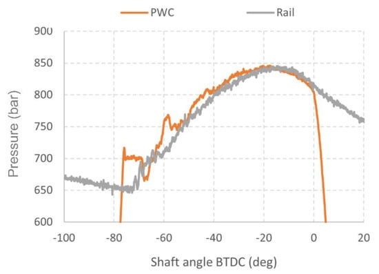
Figure 7.
PWC and rail pressure trends–Low pressure, 1500 RPM, D100.
From the start of delivery up to about −20 degrees ATDC, pressure values in PWC exceed the homologous ones measured in the rail; values tend to coincide at TDC, when piston speed is zero and delivery valve closes.
The analysis of the suction phase of the pump is generally more complex to conduct since the PT-PWC transducer, sized to the high-range working pressure, is not recommended in the suction pressure-range. Figure 8 shows the bottom part of the p-V diagram previously discussed; the same diagram reports the pressure trend measured by the PT-Inlet sensor placed upstream of the intake valve. In such a case, since the two sensors are located very close to each other, the time shift is neglected. Although the reliability of the PT-PWC transducer is limited at such low pressures, its pressure signal is in close correlation to the pressure trend upstream the intake valve.
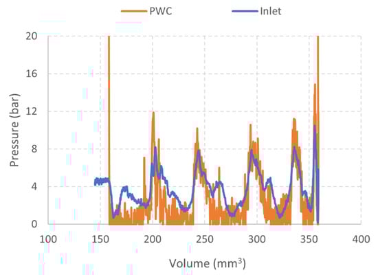
Figure 8.
Suction phase on pump indicator diagram–Low-pressure, 1500 RPM, D100.
Immediately after decompression, the suction phase begins; the feeding pressure undergoes an abrupt decrease, followed by fluctuations around the feeding pressure level. In general, these oscillations reflect the mechanical-hydraulic behavior of the relief valve (RV in Figure 1) and its combination with the feeding system features.
The influence of rail pressure level on pump behavior is analyzed keeping the speed unchanged. Figure 9 shows pressure diagrams of PWC for the three load levels at 1500 RPM. The delivery phases show quite similar trends in terms of shape. The higher the pressure, the shorter is the delivery; the end of delivery is at TDC, but the start of delivery depends on the pump load level. The diagrams highlight the volume, and therefore the stroke, which is spent to complete the compression and decompression phases.
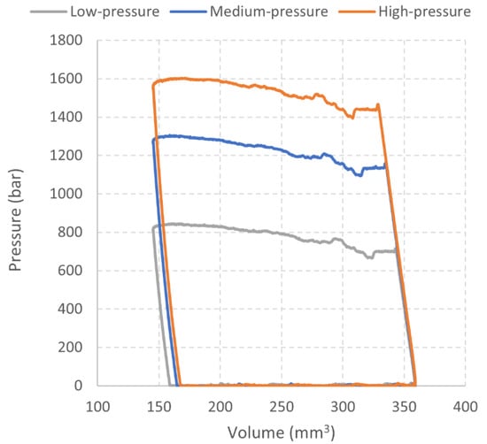
Figure 9.
PWC diagrams for Low-, Medium-, and High-Pressure levels, D100-1500 RPM.
Based on the diagrams shown in Figure 9, the extent of the pump work phases for the considered pressure levels are reported in Table 5.
Table 5.
Extent of pump work phases.
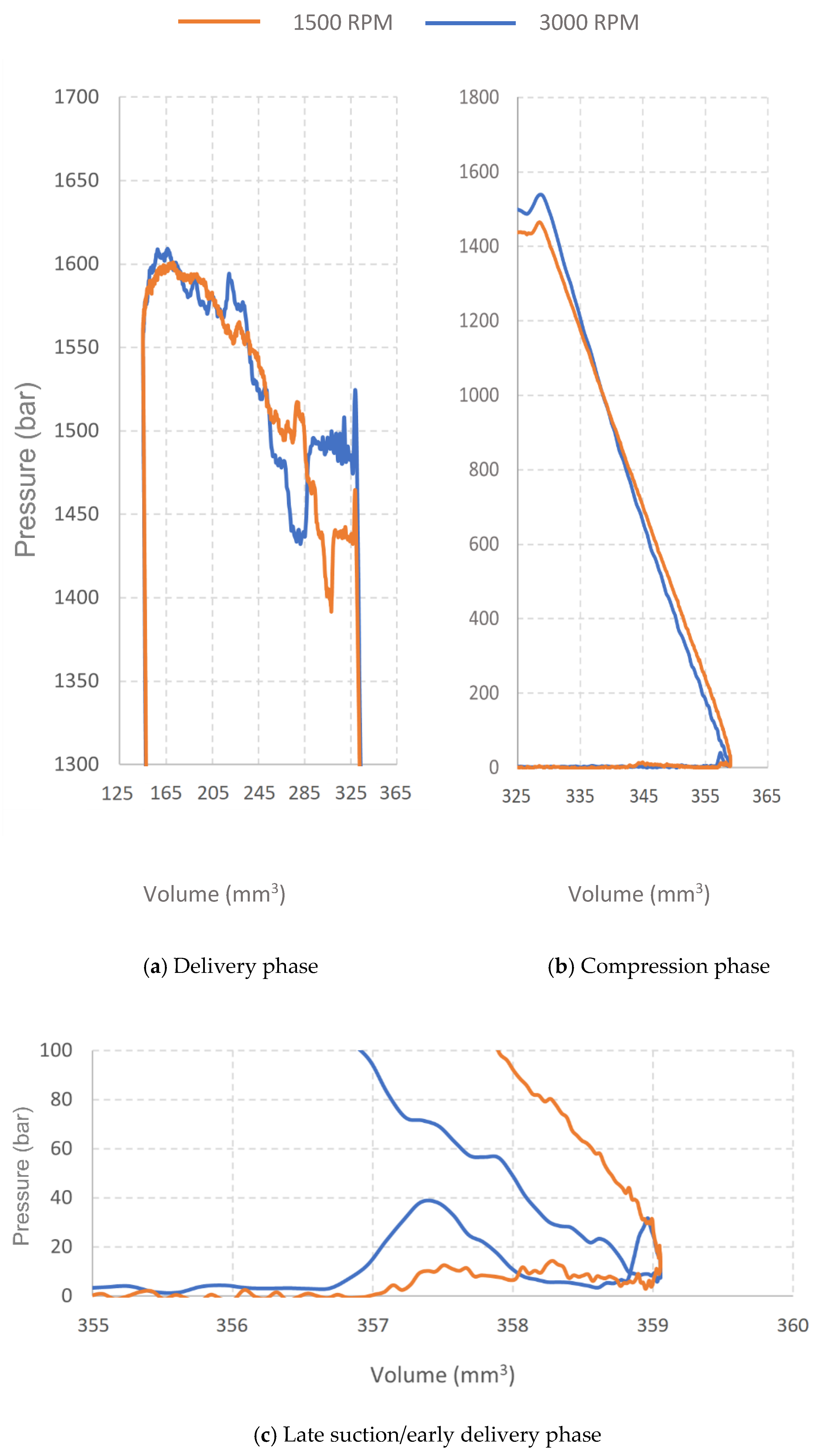
The instantaneous measurement of PWC pressure unveils the fundamental characteristics of the working phases of the pump in the typical speed range of current diesel engines. As reported below, the shaft speed represents an important operating parameter that influences the pump behavior. Keeping the same pressure level (HP) and type of fluid (D100), Figure 10 reports the trends relating to 1500 and 3000 RPM. Clearly distinct but similar trends are found in delivery phase (Figure 10a). At high speed, the average-constant pressure stage after start of delivery affects a wider portion of the process and is placed at higher pressure; once this phase is over, both trends show, in sequence: a sudden drop in pressure, a prompt rise, and some oscillations on the increasing trend with downwards concavity; at 3000 RPM pressure oscillations are more marked, but the trend suggests that delivery processes take place in similar way, regardless of the shaft speed.
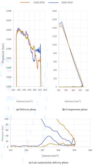
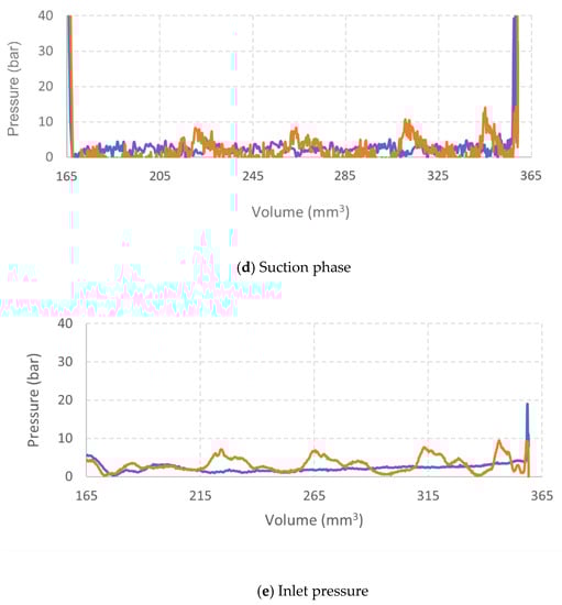
Figure 10.
PWC and inlet diagrams for 1500 and 3000 RPM, HP, D100.
Moving the attention to the compression phase (Figure 10b), pressure rise at high speed is steeper, with a more evident concavity. On one side, the higher speed reduces the time for leakage through the piston-cylinder pair; on the other side, at high speed, the PWC diagram reveals that the actual compression phase begins with an appreciable delay in respect to BDC. By observing the trends in Figure 10c, at high-speed, pressure undergoes a sudden increase before piston BDC (this event suggests the occurrence of an imperfect seal between delivery ambient and PWC); then, pressure falls back and increases again and just before the BDC the diagram intertwines, thus penalizing the suction process. Hence, the more marked pressure rise rate at high speed is partially compensated by the irregularities in the admission phase.
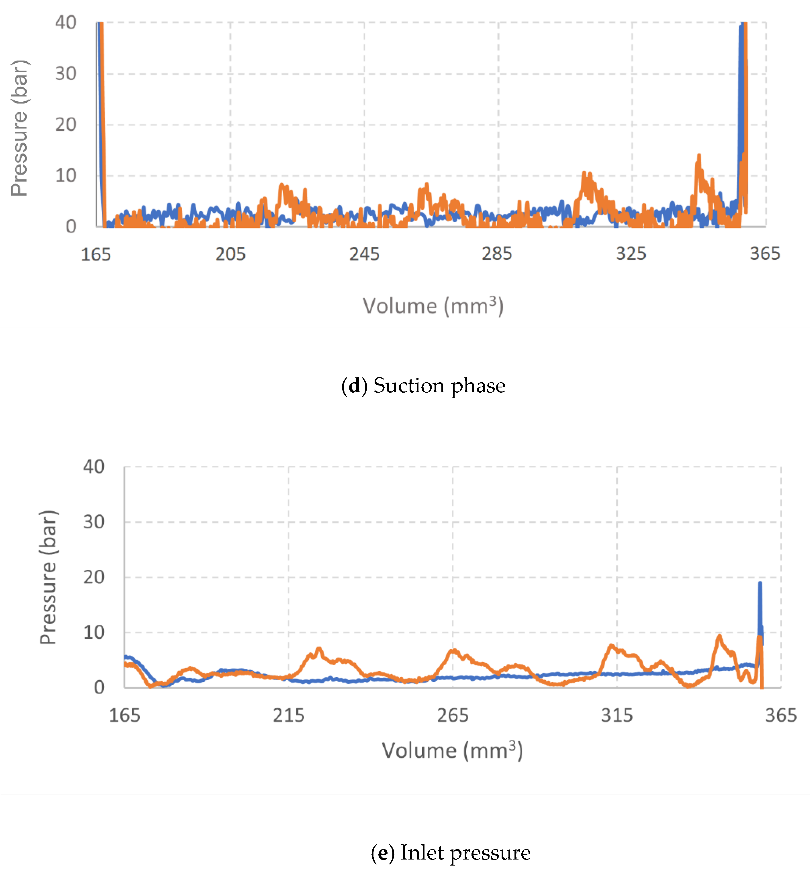
During the suction phase, pressure level at pump inlet is sensitive to speed, Figure 10d; pressure fluctuations that occur at low speed are extinguished at high speed, Figure 10e, showing a low-pass response of the whole mechanical-hydraulic system regulating pressure in suction ambient.
Table 6 reports the key features of the results shown so far graphically. Peak pressure values during the compression phase is higher at high speed; pressure rise rate is almost constant at low speed and significantly variable at high speed. The range of pressure fluctuation in suction and delivery phases are finally reported.
Table 6.
Pressure behavior during suction, compression, and delivery phases.
3.3. Pure Fluids
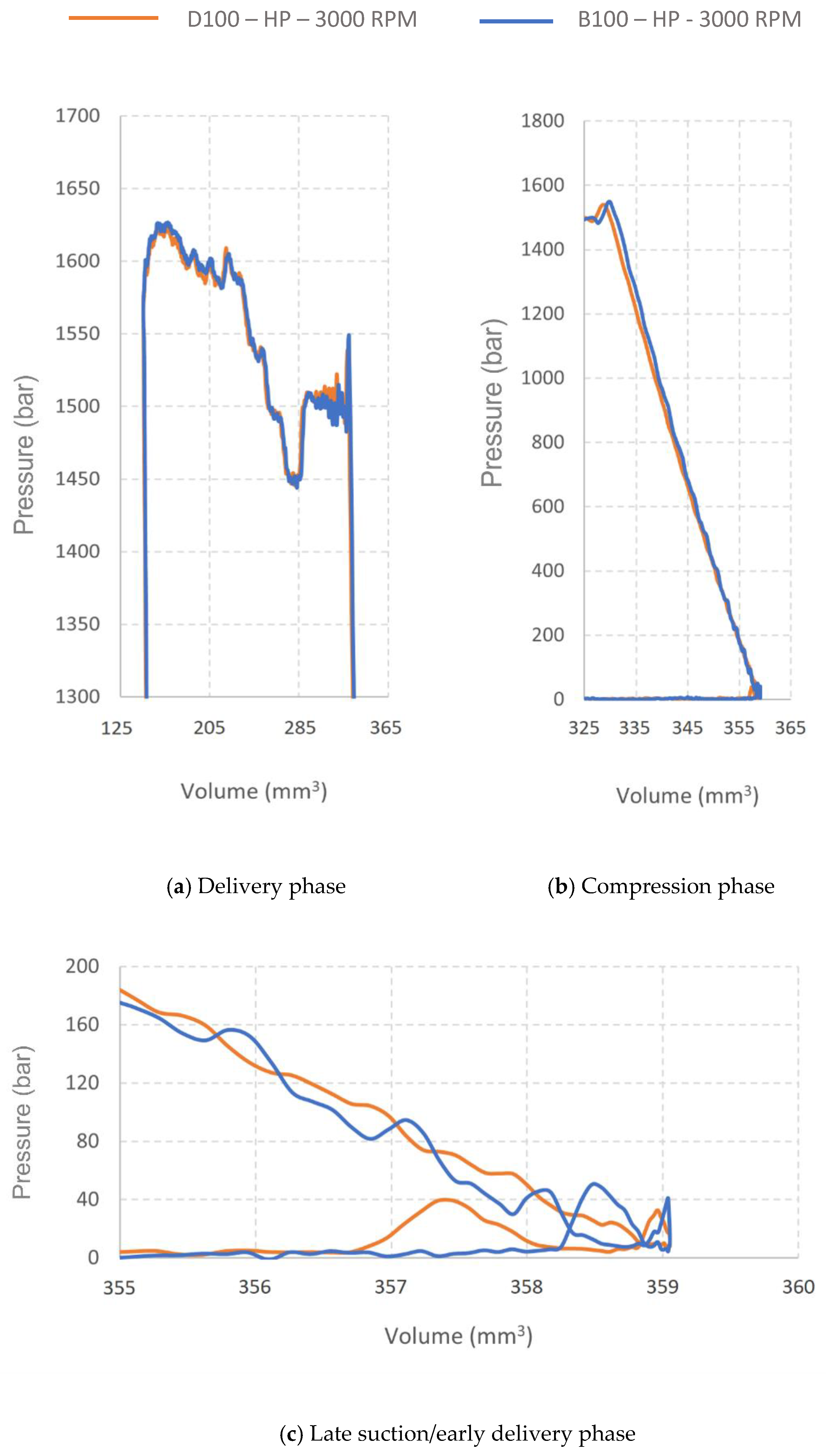
As reported in Figure 11a, there are almost overlapping trends during delivery process (HP at 3000 RPM). The compression phase starts in a similar way in the two cases and then proceeds with a more marked slope in the case of B100 (and this is compatible with the higher compressibility modulus of biodiesel); the trend is affected by a non-negligible fluctuation, whose relative weight decreases as the compression proceeds (Figure 11b). Referring to Figure 11c, in the phase of late suction/early compression of B100, the behavior differs from that of D100 but remains similar. In fact, even in the case of B100, pressure peaks appear before BDC and the diagram is intertwined. The inlet pressure trends are very similar (Figure 11d).
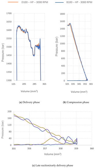
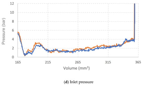
Figure 11.
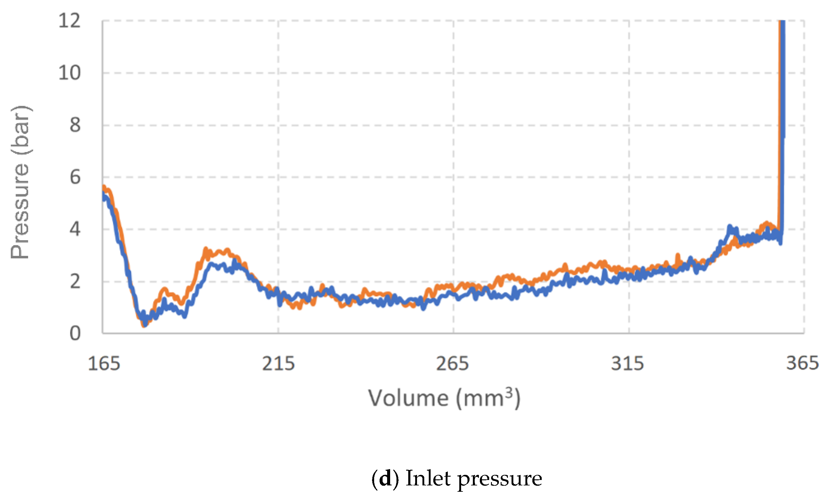
PWC and inlet diagrams for B100 and D100 at 3000 RPM, HP.
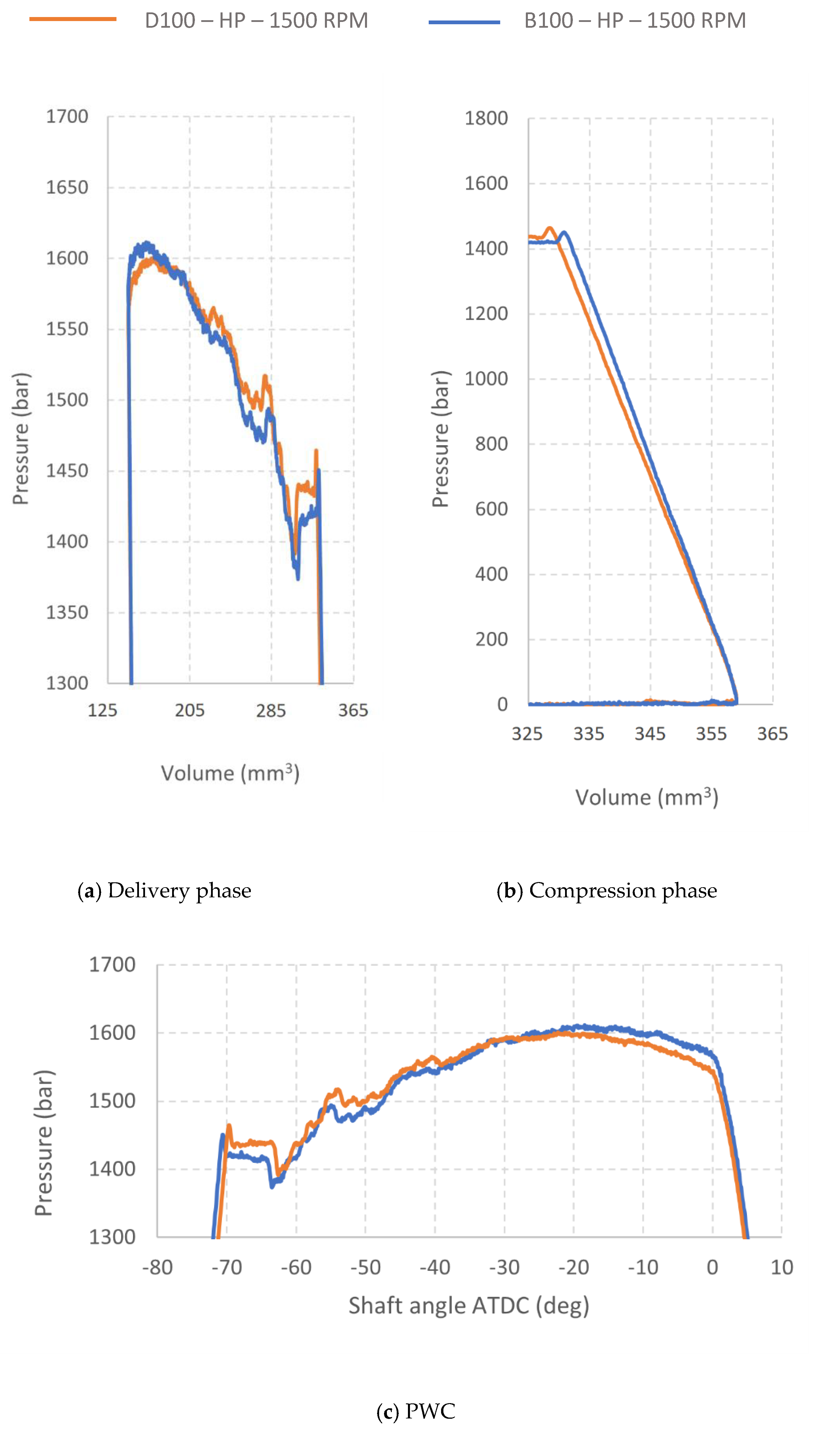
At low speed, pressure trends of B100 differ from the reference delivery phase (Figure 12a); still evident is the greater slope in the compression phase (Figure 12b) but, as for the D100, the anomalies in the end of suction/start of compression phases disappear and the different pressure rise rates are easily appreciable. By comparing pressure trends measured in PWC and rail, a wider pressure fluctuation is set with B100 (Figure 12c,d). Non-negligible differences are highlighted in the inlet pressure trends. Operating with B100, the amplitude of oscillations in suction ambient is reduced and the pressure trend is modified (Figure 12e); thus, the mechanical-hydraulic system regulating pressure in suction ambient is sensitive to the fuel type. Table 7 shows the elements to summarize the pump response to the type of fluid. The amplitude of the compression phases, the pressure rise rate, and the range of pressure fluctuations describe in a quantitative way the impact of the B100 on the pump behavior.

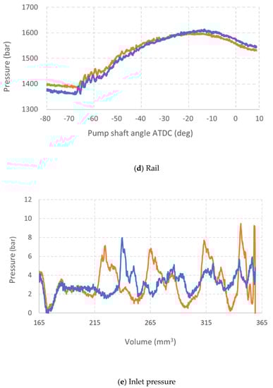
Figure 12.
PWC, rail, and inlet diagrams for B100 and D100 at 1500 RPM, HP.
Table 7.
Pump response to pure fluids.
3.4. Fuel Blends
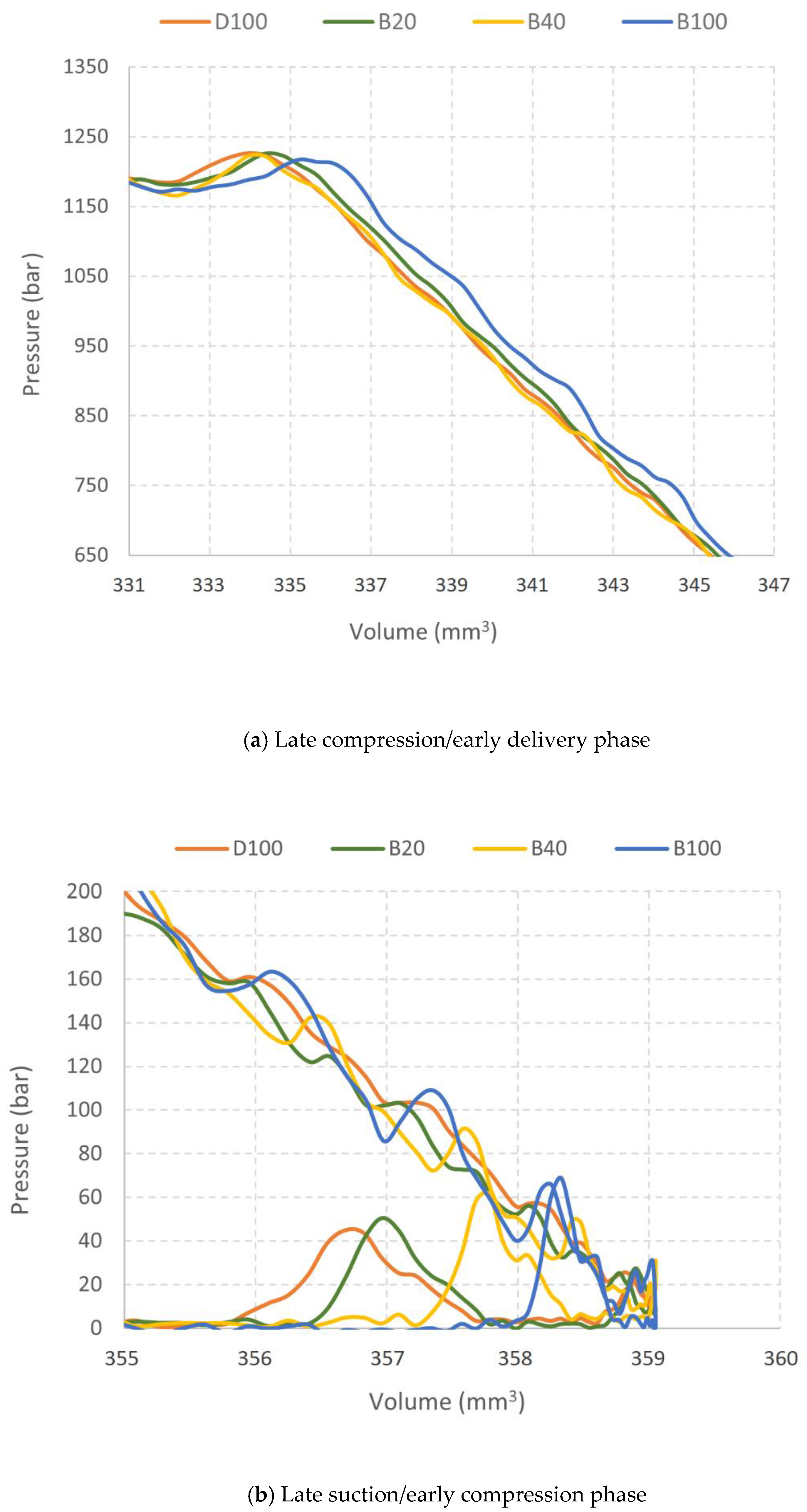
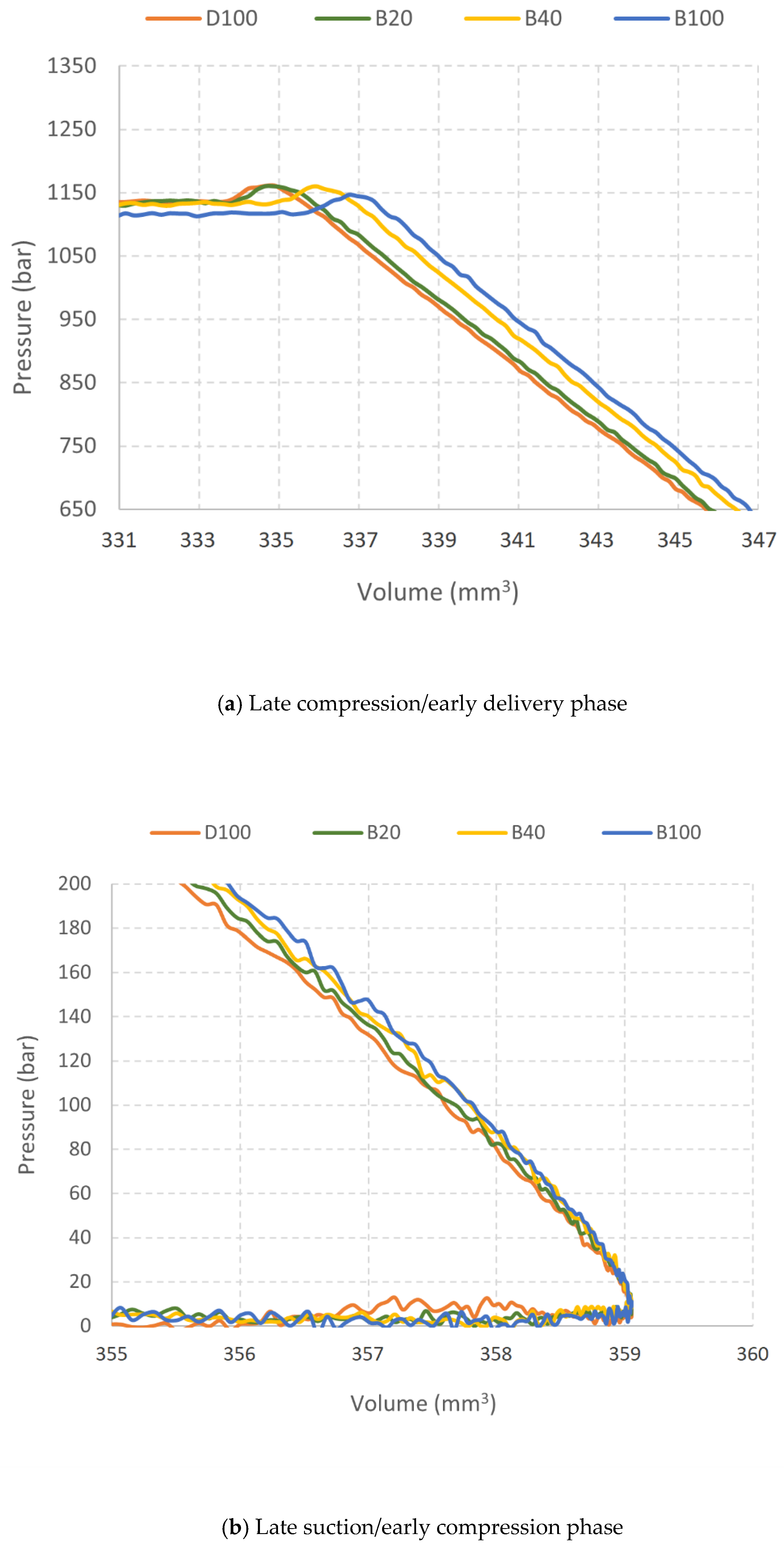
The pressure measurement in PWC allows to highlight the behavior of the pump when it operates with mixtures (B20 and B40) of the two pure fluids considered so far. In this analysis, reference is made to cases at Medium-Pressure, which proved to be well representative of what occurs both at low and at high pressure.
Analyzing the trends relating to the late compression/early delivery phase at 3000 RPM (Figure 13a), the behavior of the pump follows what has already been discussed in the previous paragraph; in this case it is interesting to point out that as the percentage of biodiesel increases, the pressure pulsations move significantly to the right, towards BDC; in summary, in this work phase the pump “feels” the fuel blend with a response roughly proportional to the biodiesel concentration. As the compression phase proceeds, both blends approach the behavior of the reference diesel fluid. The traces of D100, B20, and B40 are distinct but almost equivalent, while B100 remains above (Figure 13b).
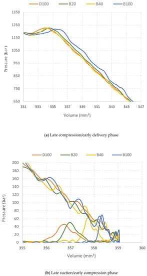
Figure 13.
PWC diagrams for pure fluids and blends at 3000 RPM, MP.
At low speed, 1500 RPM (Figure 14a,b), more regular trends are found in each phase (as already discussed above). In the compression phase (Figure 14b), the pressure trends clearly reflect the blend, with B20 and B40 clearly distinct and placed at intermediate positions between the pure fluids D100 and B100.
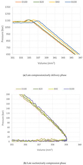
Figure 14.
PWC diagrams for pure fluids and blends at 1500 RPM, MP.
All other factors being equal, the instantaneous pressure value in PWC depends on the fluid deformability and on the extent of the leakage. The properties that affect deformability and leakage are, respectively, compressibility modulus and viscosity. At low speed (1500 RPM), the fluid has more time to flow through the piston-cylinder pair. On laminar flow, viscosity is governing and the higher concentration of more viscous fluid in the blend hinders the leakage. At 3000 RPM, the amount of leakage is hampered by the shorter duration of compression process, rather than viscosity. Since the compressibility modulus of the mixture is very close to that of the more compressible component (D100 in this case), the compression phases of B20, B40, and D100 are almost equivalent.
4. Conclusions
This article presents an approach for the experimental investigation of common rail pumps, that is based on the measurement of pressure in the working chamber of the piston. It represents an innovation in this area, since the past research activities focus on global performance (in terms of volumetric- and torque-efficiency), without investigating the internal processes of the pump. The provided experimental data allow one to effectively describe the pump operation, to separate and analyze the phases of suction, compression, delivery, and expansion, at quantitative level.
This contribution is particularly useful in characterizing the pump response both to the operating parameters (delivery pressure and shaft speed) and to the fuel type. It undoubtedly helps to unveil the processes inside the pump, which originate from the combination of relatively complex phenomena driven by leakage, by the dynamics of the valves, and by the fluid-structure deformation, on which the efficiency of the pump ultimately depends.
The results, expressed in terms of indicator diagrams and their key features, are completed through pressure measurements in the inlet and outlet environments, correlating the pump operation to the conditions of inlet and delivery chambers. Results highlight the role of the fundamental operating parameters (speed and delivery pressure) and the influence of fuel type, exploring diesel, biodiesel, and their blends.
Most importantly, the reported indicator diagrams together with the quantitative description of the key features of pump operation phases (pressure rise rate, pressure fluctuations, and phases extent) are essential to build and validate CR pump models based on piston-cylinder pair simulation, taking leakage, deformations, valves’ behavior, and fuel properties into account.
Author Contributions
F.P. and O.C. conceived and organized the work; O.C., F.P. and E.F. designed the investigations, analyzed the data, and wrote the article; F.P., E.F. and S.L. performed experiments. All authors have read and agreed to the published version of the manuscript.
Funding
This research received no external funding.
Institutional Review Board Statement
Not applicable.
Informed Consent Statement
Not applicable.
Data Availability Statement
The data presented in this study are available as text file on request from the corresponding author.
Acknowledgments
The authors acknowledge the fundamental contribution of DP Lubrificanti S.p.a., 16–04011 Aprilia (LT) IT for providing WCO biodiesel used in the current research activity.
Conflicts of Interest
The authors declare no conflict of interest.
References
- Payri, R.; Serrano, J.R.; Tormos, B.; Gomez-Vilanova, A. An objective reflection about the potential future of diesel vehicles against arguments based on energy populism. Dyna (Spain) 2019, 94, 480–482. [Google Scholar] [CrossRef]
- Jaliliantabar, F.; Ghobadian, B.; Carlucci, A.P.; Najafi, G.; Mamat, R.; Ficarella, A.; Strafella, L.; Santino, A.; De Domenico, S. A comprehensive study on the effect of pilot injection, EGR rate, IMEP and biodiesel characteristics on a CRDI diesel engine. Energy 2020, 194, 116860. [Google Scholar] [CrossRef]
- Jain, A.; Krishnasamy, A.; Pradeep, V. Computational optimization of reactivity controlled compression ignition combustion to achieve high efficiency and clean combustion. Int. J. Engine Res. 2021, 22, 2213–2232. [Google Scholar] [CrossRef]
- Hoang, A.T. Combustion behavior, performance and emission characteristics of diesel engine fuelled with biodiesel containing cerium oxide nanoparticles: A review. Fuel Process. Technol. 2021, 218, 106840. [Google Scholar] [CrossRef]
- Khan, Z.A.; Saeed, A.; Gregory, O.; Ghafoor, A. Biodiesel performance within internal combustion engine fuel system—A review. Tribol. Ind. 2016, 38, 197–213. [Google Scholar]
- Ragupathi, K.; Mani, I. Durability and lube oil contamination study on diesel engine fueled with various alternative fuels: A review. Energy Sources Part A Recovery Util. Environ. Eff. 2021, 43, 932–943. [Google Scholar] [CrossRef]
- Algayyim, S.J.M.; Wandel, A.P. Macroscopic and microscopic characteristics of biofuel spray (biodiesel and alcohols) in CI engines: A review. Fuel 2021, 292, 120303. [Google Scholar] [CrossRef]
- Hoang, A.T.; Tabatabaei, M.; Aghbashlo, M.; Carlucci, A.P.; Ölçer, A.I.; Le, A.T.; Ghassemi, A. Rice bran oil-based biodiesel as a promising renewable fuel alternative to petrodiesel: A review. Renew. Sustain. Energy Rev. 2021, 135, 110204. [Google Scholar] [CrossRef]
- Agarwal, A.K.; Park, S.; Dhar, A.; Lee, C.S.; Park, S.; Gupta, T.; Gupta, N.K. Review of experimental and computational studies on spray, combustion, performance, and emission characteristics of biodiesel fueled engines. J. Energy Resour. Technol. Trans. ASME 2018, 140. [Google Scholar] [CrossRef] [Green Version]
- Chiatti, G.; Chiavola, O.; Palmieri, F. Impact on combustion and emissions of jet fuel as additive in diesel engine fueled with blends of petrol diesel, renewable diesel and waste cooking oil biodiesel. Energies 2019, 12, 2488. [Google Scholar] [CrossRef] [Green Version]
- Ma, Q.; Zhang, Q.; Liang, J.; Yang, C. The performance and emissions characteristics of diesel/biodiesel/alcohol blends in a diesel engine. Energy Rep. 2021, 7, 1016–1024. [Google Scholar] [CrossRef]
- Agarwal, A.K.; Agarwal, D. Field-testing of biodiesel (B100) and diesel-fueled vehicles: Part 3-wear assessment of liner and piston rings, engine deposits, and operational issues. J. Energy Resour. Technol. Trans. ASME 2021, 143. [Google Scholar] [CrossRef]
- Mata, C.; Piaszyk, J.; Soriano, J.A.; Herreros, J.M.; Tsolakis, A.; Dearn, K. Impact of alternative paraffinic fuels on the durability of a modern common rail injection system. Energies 2020, 13, 4166. [Google Scholar] [CrossRef]
- Yildiz, I.; Caliskan, H.; Mori, K. Energy, exergy and environmental assessments of biodiesel and diesel fuels for an internal combustion engine using silicon carbide particulate filter. J. Therm. Anal. Calorim. 2021, 145, 739–750. [Google Scholar] [CrossRef]
- Macián, V.; Tormos, B.; Bermúdez, V.; Bastidas, S. Development of a floating liner test rig and lubrication model for the study of the piston compression ring friction force under fully flooded and starved lubrication. Tribol. Int. 2021, 160, 107034. [Google Scholar] [CrossRef]
- Yang, J.; Wu, J.; Zhang, Y.; Tao, W.; Fan, X.; Xie, P. Optimization Study on Key Parameters Influencing Friction and Slap Characteristics of Pistons. Neiranji Gongcheng/Chin. Intern. Combust. Engine Eng. 2021, 42, 95–103. [Google Scholar] [CrossRef]
- Lyu, Y.J.; Kang, J.X.; Zhang, Y.F.; Luo, H.B. Research progress of anti-friction and anti-wear of piston-cylinder liner system in internal combustion engine. Jiaotong Yunshu Gongcheng Xuebao/J. Traffic Transp. Eng. 2020, 20, 21–34. [Google Scholar] [CrossRef]
- Jain, A.; Porpatham, E.; Thipse, S.S. Effect of intake valve timing, duration strategies with swirl ratio on volumetric efficiency of single cylinder diesel engine. Int. J. Mech. Prod. Eng. Res. Dev. 2020, 10, 415–434. [Google Scholar] [CrossRef]
- Moser, S.; Edwards, K.D.; Schoeffler, T.; Filipi, Z. CFD/FEA Co-Simulation Framework for Analysis of the Thermal Barrier Coating Design and Its Impact on the HD Diesel Engine Performance. Energies 2021, 14, 2044. [Google Scholar] [CrossRef]
- Magno, A.; Mancaruso, E.; Vaglieco, B.M. Effects of both blended and pure biodiesel on waste heat recovery potentiality and exhaust emissions of a small CI (compression ignition) engine. Energy 2015, 86, 661–671. [Google Scholar] [CrossRef]
- Catania, A.E.; Ferrari, A. Experimental analysis, modeling, and control of volumetric radial-piston pumps. J. Fluids Eng. Trans. ASME 2011, 133, 081103. [Google Scholar] [CrossRef]
- Qi, B.; Yong, Z. Tribological study of piston–cylinder interface of radial piston pump in high-pressure common rail system considering surface topography effect. Proc. Inst. Mech. Eng. Part J J. Eng. Tribol. 2020, 234, 1381–1395. [Google Scholar] [CrossRef]
- Wang, H.; Xiang, J.; Wang, C. Simulation of Micro Motion of Common Rail High-Pressure Fuel Pump Plunger. Neiranji Gongcheng/Chin. Intern. Combust. Engine Eng. 2019, 40, 65–71. [Google Scholar] [CrossRef]
- Iordache, R.C.; Petrea, N.D.; Bujoreanu, C. Wear’s Issues on High-Pressure Common Rail Pumps. In IOP Conference Series: Materials Science and Engineering; IOP Publishing: Bristol, UK, 2020; Volume 724. [Google Scholar]
- Petrea, N.D.; Bujoreanu, C.; Ripanu, I.E. Influence of Ball-Seat Contact on the Noise Emissions from Common-Rail Pump Outlet VALVE opening. In IOP Conference Series: Materials Science and Engineering; IOP Publishing: Bristol, UK, 2018; p. 042012. [Google Scholar]
- Petrea, N.D.; Bujoreanu, C.; Alaci, S. Analysis of the Noise Emissions of a Common-Rail Pump before and after an Endurance Test. In IOP Conference Series: Materials Science and Engineering; IOP Publishing: Bristol, UK, 2019. [Google Scholar]
- Rückert, M.; Murrenhoff, H.; Heitzig, S. Influence of a New Hollow Piston Design on Volumetric Losses of a Common-Rail Pump. In Proceedings of the ASME/BATH 2017 Symposium on Fluid Power and Motion Control, FPMC 2017, Sarasota, FL, USA, 16–19 October 2017. [Google Scholar]
- Yue, G.; Qiu, T.; Dai, H.; Lei, Y.; Zhao, N. Rail pressure control strategy based on pumping characteristics for the common rail fuel system. Adv. Mech. Eng. 2018, 10. [Google Scholar] [CrossRef]
- Ferrari, A.; Vitali, R. Instantaneous torque, energy saving and flow rate ripple analysis of a common rail pump equipped with different delivery-pressure control systems. Int. J. Engine Res. 2018, 19, 1036–1047. [Google Scholar] [CrossRef]
- Cavallo, M.D.; Chiavola, O.; Frattini, E.; Palmieri, F. Fuel Influence on Single-Piston Common Rail Pump Performance. In Proceedings of the 15th International Conference on Engines & Vehicles—Status, Capri, Italy, 12–16 September 2021. Accepted for publication 2021-24-0063. [Google Scholar]
- Botwinska, K.; Mruk, R.; Krawiec, L. Modelling of the work processes high-pressure pump of common rail diesel injection system. In Proceedings of the E3S Web of Conferences, Kraków, Poland, 17–19 May 2016. [Google Scholar]
- Catania, A.E.; Ferrari, A.; Mittica, A. High-pressure rotary pump performance in multi-jet common rail systems. In Proceedings of the 8th Biennial ASME Conference on Engineering Systems Design and Analysis (ESDA 2006), Torino, Italy, 4–7 July 2006. [Google Scholar]
- Giuffrida, A.; Ficarella, A.; Laforgia, D. Study of the delivery behaviour of a pump for common rail fuel injection equipment. Proc. Inst. Mech. Engineers. Part I J. Syst. Control Eng. 2009, 223, 521–535. [Google Scholar] [CrossRef]
- Bosch, R. Automotive Handbook, 10th ed.; Wiley: Hoboken, NJ, USA, 2019; p. 1750. [Google Scholar]
- Payri, R.; Salvador, F.J.; Gimeno, J.; Bracho, G. The effect of temperature and pressure on thermodynamic properties of diesel and biodiesel fuels. Fuel 2011, 90, 1172–1180. [Google Scholar] [CrossRef] [Green Version]


Publisher’s Note: MDPI stays neutral with regard to jurisdictional claims in published maps and institutional affiliations. |
© 2021 by the authors. Licensee MDPI, Basel, Switzerland. This article is an open access article distributed under the terms and conditions of the Creative Commons Attribution (CC BY) license (https://creativecommons.org/licenses/by/4.0/).