Article

Study on Multiphysics Coupling and Automatic Neutronic Optimization for Solid Tritium Breeding Blanket of Fusion Reactor

1
Southwestern Institute of Physics, P.O. Box 432, Chengdu 610041, China
2
Fusion Power System, LLC, San Diego, CA 92127, USA
*
Author to whom correspondence should be addressed.
Energies 2021, 14(17), 5442; https://doi.org/10.3390/en14175442
Submission received: 12 July 2021 / Revised: 20 August 2021 / Accepted: 26 August 2021 / Published: 1 September 2021
(This article belongs to the Special Issue Nuclear Fusion Energy Development)

Abstract

:
A tritium breeding blanket (TBB) is an essential component in a fusion reactor, which has functions of tritium breeding, energy generation and neutron shielding. Tritium breeding ratio (TBR) is a key parameter to evaluate whether the TBB could produce enough tritium to achieve tritium self-sufficiency (TBR > 1) for a fusion reactor. Current codes or software struggle to meet the requirements of high efficiency and high automation for neutronic optimization of the TBB. In this paper, the multiphysics coupling and automatic neutronic optimization method study for a solid breeder TBB is performed, and a corresponding code is developed. A typical module of China fusion engineering test reactor (CFETR) helium cooled ceramic breeder (HCCB) TBB was selected, and a 3D neutronics model of an initial scheme is developed. The automatic neutronic optimization was performed by using the developed code for verification. Results indicate that the TBR could increase from 1.219 to 1.282 (~5.17% improvement), and that the maximum temperature of each type of material in the optimized scheme is below the allowable temperature. It is of great scientific significance and engineering value to explore and study the algorithm for automatic neutronic optimization and the code development of the TBB.

1. Introduction

The tritium breeding blanket (TBB) is an essential component to achieve tritium production, energy generation and extraction in a fusion reactor. The solid breeder TBB is an important alternative for a demonstration fusion reactor (DEMO) or a fusion power plant. Tritium self-sufficiency is a significant goal, and the tritium breeding ratio (TBR) is a key parameter to evaluate whether the TBB can produce enough tritium to achieve tritium self-sufficiency for fusion reactor, which can be calculated as follows Equation (1)
T B R = [ N 6 L i σ 6 L i ( n , a ) ( r , E ) + N 7 L i σ 7 L i ( n , a ) ( r , E ) ] ϕ ( r , E , t ) d E d r S p l a s m a
N6Li and N7Li are the atom densities of 6Li and 7Li, respectively; σ6Li and σ7Li are the cross-sections of the (n, T) reactions of 6Li and 7Li, respectively; Φ(r, E, t) is the neutron flux distribution; Splasma is the generation rate of fusion neutron in plasma. In brief, TBR represents the average atom number of tritium produced in the TBB for every fusion neutron consumed.
However, the TBR of the fusion reactor can be impacted by a number of factors, including the geometries (the opening ports to install the corresponding heating and diagnostic equipment [1,2], and a heterogeneous model of the blanket [3]), materials (type, density, enrichment), nuclear libraries (uncertainty), and neutron transport codes (uncertainty). Meanwhile, the tritium losses occur during the fuel cycle because of tritium decay, leakage, extraction, and retention, which is a considerable challenge to tritium-sustaining. Therefore, a higher TBR is needed.
According to the above constraints, a general neutronic optimization flow chart for the TBB of the fusion reactor is shown in Figure 1 [4]. The procedures mainly include six steps: (1) An initial design for the TBB needs to be made (including the choice of functional materials, structural material, and coolant, and the set of geometry parameters). (2) The Monte-Carlo (MC) neutronic transport calculation of the TBB is performed, and the TBR, nuclear heat, and neutron flux are obtained as inputs for a following FEM analysis. (3) Thermal-fluid FEM analysis is performed by using ANSYS, and some design parameters such as fluid pressure distribution and pressure drop are obtained. (4) The temperature distribution of the first wall (FW) and TBB (including the regions of the tritium breeding and neutron multiplier) can be calculated by ANSYS Thermal. (5) A structural analysis is performed by ANSYS Thermo-mechanics, and the primary and thermal stresses can be obtained. (6) The optimized TBB design can be made. The neutronics optimization should be returned back to the first step, and geometry parameters should be adjusted accordingly if the TBB design does not meet the design requirements of the pressure drop, the temperature of the FW/TBB and thermal stresses. Each physics field analysis is performed respectively, and one-way data transmission is adopted.
To ensure that the maximum temperature of each type of material is lower than its corresponding allowable temperature, real-time monitoring for the temperature distribution of the TBB is necessary during the process of neutronic optimization. Calculation accuracy can be ensured through the above flow chart, yet a huge computational expense is caused. On the one hand, 3D thermal FEM and iterative simulations call for huge calculation expense. The same holds true for a 3D MC simulation, since one needs fine mesh tallies overlaid over explicit geometry in general, and so many particles are needed to reduce the MC relative deviation. On the other hand, such explicit 3D models impose too much CPU time and memory to be working modules of iterative optimization algorithms. Therefore, the cycle time is too long during the optimization process, which is not suitable for the rapid automatic optimization of the TBB.
In view of the above constraints, the method study of the multiphysics coupling and neutronics automatic optimization for a solid breeder TBB was performed, and a corresponding code is developed and verified, which consists of four modules: (1) the neutronic transport calculation module (MCNP-4C [5,6]); (2) the automatic neutronic optimization module; (3) the 1D thermal feedback module; (4) the packing fraction (PF) of the feedback module (only for pebble beds; PF is the ratio of the volume of pebble beds to the whole volume of the container). This code can realize the multiphysics coupling, increase the optimization efficiency and ensure data transmission without losses.

2. D Thermal Feedback Module

2.1. Code Development

Figure 2 shows the CAD model of the latest design of CFETR [1] HCCB TBB [7]. It mainly consists of an armor (which prevents plasma sputtering), a first wall (FW), tritium breeder zones, neutron multiplier zones, caps, cooling plates (CP), a distribution plate, a shielding plate and a gathering plate. According to the 3D CAD model, a simplified model of the TBB with a sandwich-like layout for 1D thermal calculation is shown as Figure 3. The 1D simplified model of the breeding zone includes the tritium breeder, neutron multiplier and structural material for rapid thermal calculation (shown in Figure 3).
In this paper, one tritium breeder region with two adjacent cooling plates (CP) is defined as one breeder unit (BU), and one neutron multiplier region with two adjacent CP is defined as one multiplier unit (MU). According to the BU and MU, the 1D steady-state heat conduction equation is expressed as follows:
{ d 2 T ( x ) d x 2 + ϕ ˙ λ ( T ( x ) ) = 0 , x ( 0 , δ ) x = 0 , λ ( T ( x ) ) d T ( x ) d x + h ( T f 1 T ( x ) ) = 0 x = δ , λ ( T ( x ) ) d T ( x ) d x + h ( T f 2 T ( x ) ) = 0
where T(x) is the temperature distribution of the breeding region; ϕ ˙ is the internal heat source of one tritium breeder region or neutron multiplier region; λ(T(x)) is the effective heat conductivity coefficient of the pebble beds; δ is the total radial thickness of the study object; h is the convective heat transfer coefficient; T f 1 and T f 2 are the left- and right-side fluid temperature, respectively.
In consideration of reducing computational expense effectively, a constant heat conductivity under an average temperature is adopted in the CPs because the CP thickness in radial is small (only 1 cm), with a small temperature gradient, and the thermal conductivity is insensitive to the temperature changes. Therefore, an analytical solution of temperature distribution of the CP can be calculated as follows:
T ( x ) = ϕ ˙ 2 λ 0 x 2 + c 1 x + c 2 , x [ 0 , δ ]
c 1 = h ( T f 2 T f 1 ) 2 ( λ 0 + h δ )
c 2 = ϕ ˙ 2 λ 0 δ 2 + ϕ ˙ δ h + ( T f 2 + T f 1 ) 2
λ 0 is the heat conductivity under average temperature of each CP.
In contrast, the tritium breeder region and the neutron multiplier regions are relatively thicker in the radial, with a high-temperature gradient. The effective heat conductivity coefficient in the pebble beds should not be considered as a constant value. The calculation methods of the effective coefficients in Be pebble beds and Li4SiO4 pebble beds are shown in Section 2.2.
Then, spatial discretization is performed by the finite difference method (FDM), and the discretization equation can be derived as follows. Here, Δx is the spatial step.
{ ( a + b T f 1 Δ x h ) T 0 + a + b T f 1 Δ x T 1 = h T f 1 T i 1 2 T i + T i + 1 = ϕ ˙ Δ x 2 λ , i = 1 , 2 , 3 , , n 1 a + b T f 2 Δ x T n 1 + ( a + b T f 2 Δ x h ) T n = h T f 2
Next, the discretization equation can be solved by using the chase-after method of tridiagonal equations, which is expressed as follows:
[ a + b T f 1 Δ x h a + b T f 1 Δ x 1 2 1 1 2 1 1 2 1 a + b T f 2 Δ x a + b T f 2 Δ x h ] [ T 0 T 1 T 2 T n 1 T n ] = [ h T f 1 ϕ ˙ Δ x 2 λ ϕ ˙ Δ x 2 λ h T f 2 ]

2.2. Code Verification

The HCCB TBB typical module based on the latest design of the CFETR HCCB blanket was selected for the verification. Firstly, a neutronics model was needed for 3D transport calculation. Yet, high-fidelity modelling and transport calculation are very challenging tasks for a solid breeder TBB because the TBB surrounds the high-temperature plasma with a complex geometry, an intense heterogeneous neutron flux distribution and neutrons with a large energy span. Therefore, a 3D homogeneous neutronic model was adopted and developed, as shown in Figure 4. It is proven that the homogeneous neutronics model has a small impact on the performance of the CFETR HCCB TBB [3]. In the homogeneous model, the different materials of the breeding blanket were assumed to be mixed according to their volume fractions in each functional region. Reflecting boundaries were applied, including both toroidal and poloidal directions. The toroidal widths and poloidal length of the blanket module were both 120 cm, and the radial thickness was 80 cm (2.5 cm for FW, 56.5 cm for the breeding zone, 15 cm for manifold, and 5 cm for the back plate). The poloidal length of the caps was the same as that of the FW. ODS steel was selected as the structural material, Li4SiO4 [8] (the enrichment of 6Li is 90%) as the tritium breeder in the pebble bed regions, and Be as the neutron multiplier. The whole blanket module was divided into nine regions: five regions for the tritium breeding and four for the neutron multiplication. There were eight CPs providing cooling and structural support for the blanket box. The initial radial dimensions of the blanket module are listed in Table 1.
The transport calculation was performed by MCNP-4C based on FENDL-2.1 [6]. One million particles were taken into account in the simulation, and the MC relative deviation could reduce to ~0.1%. A general neutron source of a Gaussian fusion energy spectrum was added in front of the FW, and reflecting boundaries were adopted in toroidal and poloidal. F4 and F6 tallies were performed for calculating TBR and average power density, respectively.
The packing fraction of the Li4SiO4 pebble bed was 62%, and the density was 1404.672 (kg/m3). The fitting formulas of the effective thermal conductivity and effective specific heat at normal pressure are expressed as follows [9,10]:
λ ( T ) = 0.768 + 4.96 × 10 4 T ( W / m K )
C p ( T ) = 940 + 1.46 T + 4.01 × 10 6 T 2 ( J / k g K )
The packing fraction of the Be pebble bed is 80%, and the density is 1406.4 (kg/m3). The fitting formula of the effective thermal conductivity is expressed as [11,12,13]
λ ( T ) = 6.234 ( 1 + 353 ( α B e α F e ) ( T 300 ) ) ( W / m K )
α B e and α F e are the coefficients of the thermal expansion of the Be and Fe (a type of impurity in the Be pebble bed), respectively. The empirical formulas are written as follows:
α B e = 8.43 × 10 6 × ( 1   +   1.36 × 10 3 T 3.53 × 10 7 T 2 ) ( K 1 )
α F e = 7.18422 × 10 6 + 1.21304 × 10 8 T 6.25 × 10 12 T 2 ) ( K 1 )
The density of the ODS steel at room temperature was 7847 (kg/m3). The fitting formulas of the thermal conductivity and effective specific heat at the normal pressure are expressed as follows:
λ ( T ) = 34.02857 0.01025 T ( W / m K )
C p ( T ) = 536.82457 0.11405 T + 7.7381 × 10 4 T 2 ( J / k g K )
The simplified calculation method of the heat source of each region was utilized. The heat removed by the helium coolant in the FW consists of three parts: (1) the surface heat flux of the FW (0.5 MW/m2), (2) the nuclear heat deposited in the FW, and (3) half of the nuclear heat deposited in the Li-1 region. The heat removed by the helium coolant in the breeding zone included half of the nuclear heat deposited in the Li-1 region and the nuclear heat deposited in all regions behind.
Then, the verification for the 1D thermal feedback module could be performed. The 1D average power density distribution of the TBB under a NWL (neutron wall loading) of 2.5 MW/m2 is illustrated in Figure 5, which is also considered as the input for the thermal calculation [14].
The inlet and outlet temperatures of the coolant were 300 °C and 500 °C. The solid breeder TBB is periodic in the toroidal direction, and a typical layer model (shown as Figure 6a) was adopted for the 3D thermal analysis in ANSYS-14. The mesh dissection is shown as Figure 6b. Then, the 1D radial temperature distribution of the TBB can be calculated as shown in Figure 7a, and the results calculated by ANSYS-14 are shown in Figure 7b.
Results indicate that (1) the 1D radial temperature distribution result is consistent with the one calculated by ANSYS; (2) the maximum temperatures of the Li4SiO4 calculated by these two codes are 1456.4 K and 1448.2 K, respectively, and both of them are located in Li-5; (3) the maximum temperatures of the Be as calculated by these two codes are 1073 K and 1082.4 K, respectively, and both of them are located in the Be-1 region. Therefore, the 1D thermal feedback module can be used for rapid thermal calculation of the TBB during the process of neutronic optimization.

3. PF Feedback Module

Figure 8 shows the relationship between the average packing fraction and the container size of the Li4SiO4 pebble beds, in which the diameter of pellets D is assumed to be 1 mm, and Ly means the radial length of the container. According to the results in Figure 8, the average PF of each tritium breeder region can be obtained by interpolation, which is shown as follows:
P F i ( δ i d ) = P F a + ( δ i d δ a d ) P F b P F a δ b d δ a d
δ i is the radial length of the ith tritium breeder region; δ a and δ b are the floor and upper radial thickness for the interpolation, respectively; d is the diameter of the Li4SiO4 pellet; PFi is the average packing fraction of the ith tritium breeder region; PFa and PFb are the floor and upper average packing fraction for the interpolation, respectively. In brief, PFi can be obtained by interpolating between two adjacent points.
The average density of the tritium breeder region and the atom density of 6Li and 7Li can be calculated as follows:
ρ i L i 4 S i O 4 = ρ L i 4 S i O 4 P F i
ρ L i 4 S i O 4 is the density of Li4SiO4, and ρ i L i 4 S i O 4 is the average density of the ith tritium breeder region.
N i 6 L i and N i 7 L i are the atom densities of 6Li and 7Li of the ith tritium breeder region, respectively; N0 is Avogadro’s number; A L i 4 S i O 4 is the relative atomic mass of Li4SiO4; A 6 L i and A 7 L i are the relative atomic masses of 6Li and 7Li, respectively; ε 6 L i and ε 6 L i are the enrichment of 6Li and 7Li, respectively.
N i 6 L i = 4 N 0 ρ i L i 4 S i O 4 c 6 L i A L i 4 S i O 4
N i 7 L i = 4 N 0 ρ i L i 4 S i O 4 c 7 L i A L i 4 S i O 4
c 6 L i = 1 1 + A 6 L i A 7 L i ( 1 ε 6 L i 1 )
c 7 L i = 1 1 + A 7 L i A 6 L i ( 1 ε 6 L i 1 )

4. Automatic Neutronic Optimization Module

4.1. Limits and Goals of Optimization

Limits and goals of the automatic neutronic optimization of the TBB mainly include the following:
(1)
Temperature limits
The maximum temperature of the blanket structure ODS, multiplier Be, and solid breeder Li4SiO4 should be lower than 923, 923 and 1173 K, respectively;
(2)
Goals of engineering feasibility
The radial thickness of each tritium breeder region and neutron multiplier region should be not less than 1cm at the minimum.
The radial thickness of the optimization step should be between 0.1 cm and 0.5 cm.
The total radial thickness of the breeder zone and of each CP thickness should be assumed to be constant during automatic neutronic optimization.

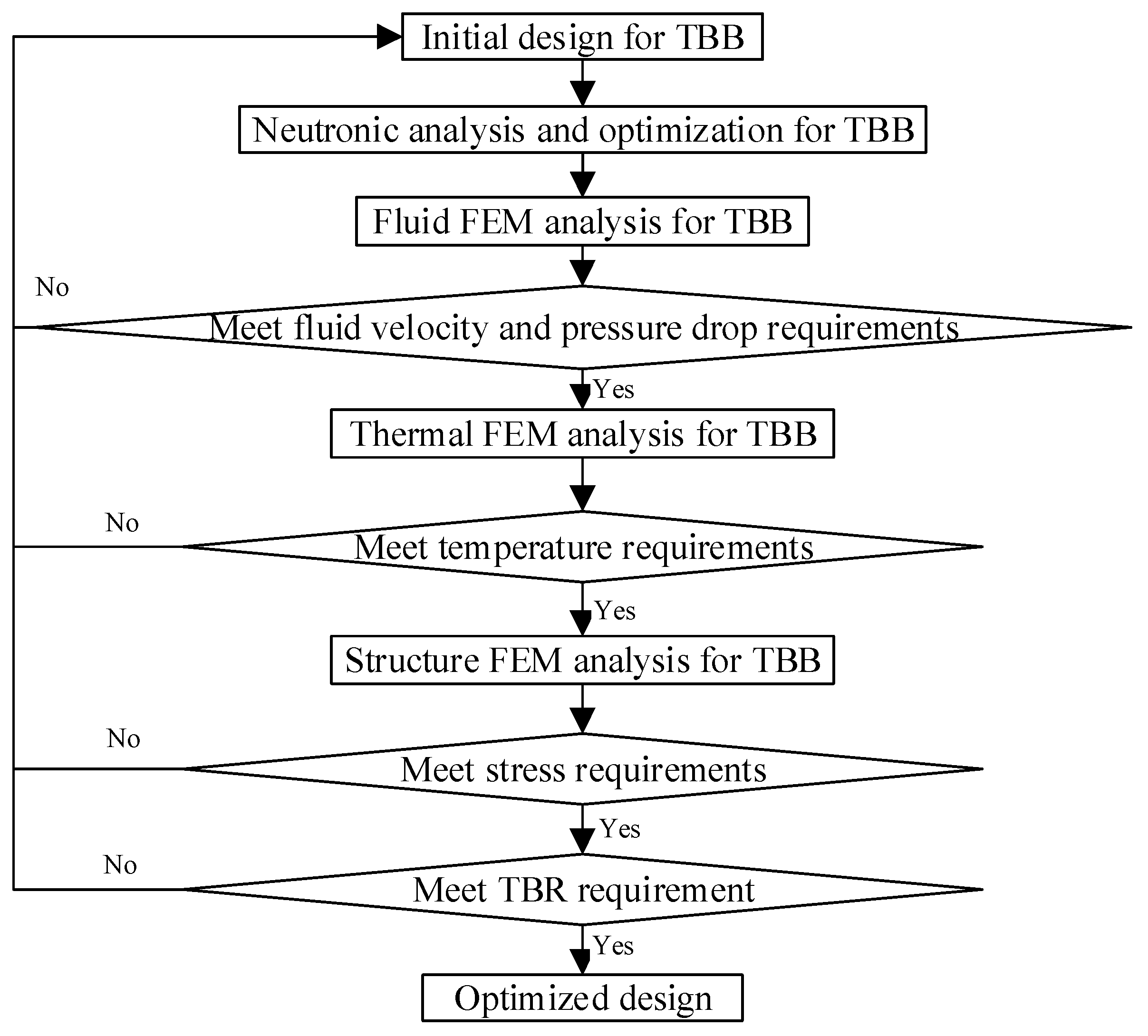
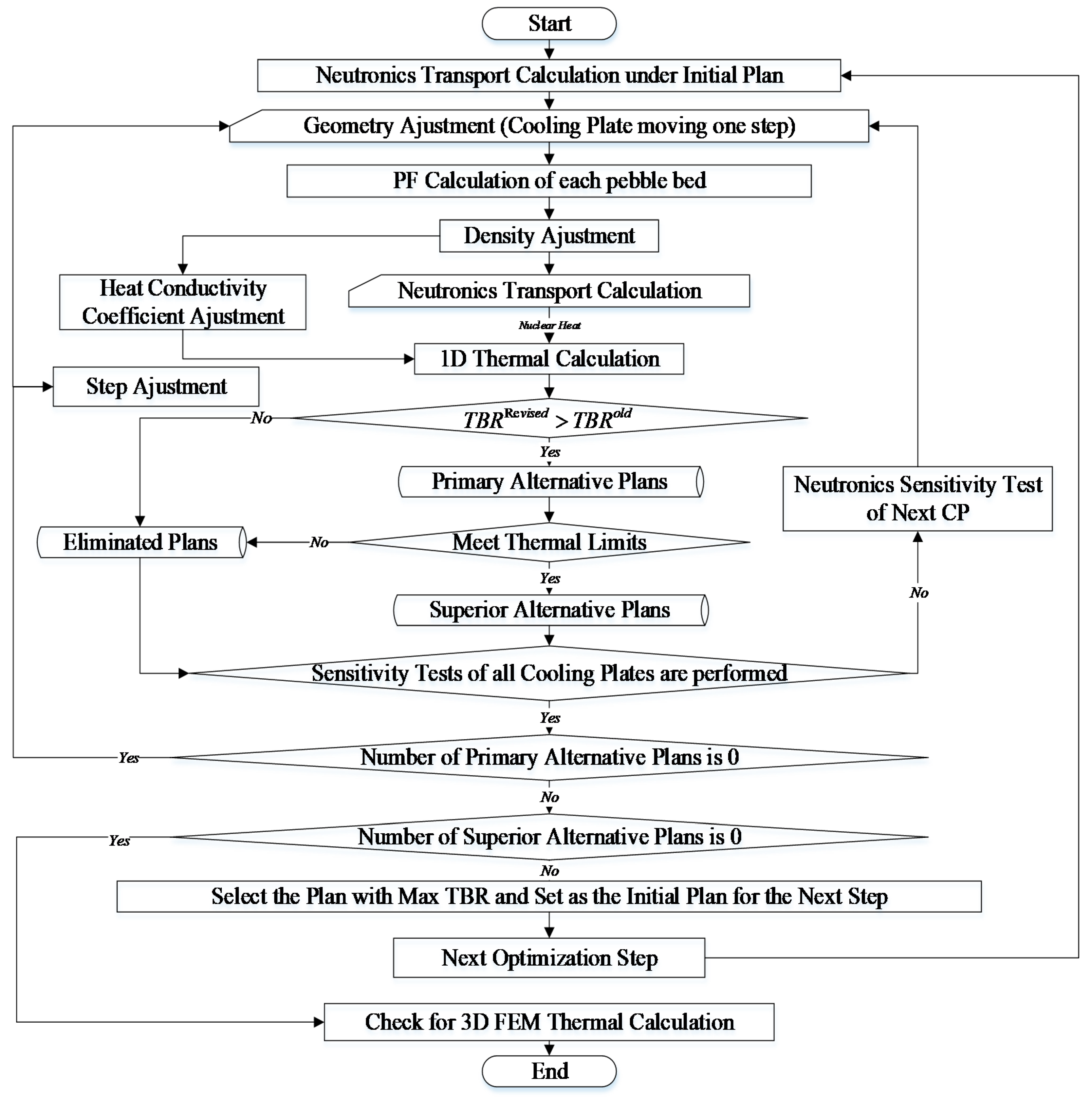
4.2. Method of Automatic Optimization

The flow chart of the automatic neutronic optimization of the TBB is illustrated in Figure 9, which mainly includes the five following steps:
(1)
Step 1
The 3D Monte-Carlo neutronic transport calculation based on the initial design of the TBB is performed, and the initial neutronic performance parameters (such as TBR, nuclear heat distribution, etc.) can be obtained.
(2)
Step 2
An assumption of the radial thickness of the optimization step and geometry adjustment with one step length of each CP is performed in sequence. The scheme libraries of the current optimization step are formed. Then, the PF of each pebble bed of each scheme is updated through the PF feedback module, and the effective heat conductivity coefficient of each pebble bed is also updated for the subsequent 1D thermal calculation. Next, the neutronic analysis of each scheme is performed, and the neutronic performance parameters (TBR and nuclear heat distribution) can be obtained. Power density of each region can be calculated as follows:
ϕ i j = F 6 i j N W L S 14.1 × V i j P F i j
P F i j is the PF of the ith region of the jth scheme; ϕ i j is the average power density of the ith region of the jth scheme; F 6 i j is the nuclear heat deposition of the ith region of the jth scheme; N W L is the neutron wall load; S is the area facing to the plasma; V i j is the volume of the ith region of the jth scheme.
Then, thermal analysis of each scheme is performed through the 1D thermal feedback module, and the 1D radial temperature distribution of each scheme can be obtained. Next, a primary filter according to the TBR of each scheme is set up. The specific scheme belongs to primary alternatives if its TBR is greater than that of the initial schemes; otherwise it is eliminated.
(3)
Step 3
The secondary filter according to the temperature limits of each primary alternative is set up. The specific primary alternative is assumed to be the secondary alternative if the maximum temperature of each type of material is lower than its corresponding temperature limit; otherwise it is automatically abandoned.
(4)
Step 4
Cycle through Step 2 and Step 3 until the filters of all schemes have been completed. An adjustment of the radial thickness of the optimization step is made if the number of primary alternatives is 0 (there is no scheme with the TBR greater than that of the initial schemes). Continue through Step 2 and Step 3 until the radial thickness of the optimization step reaches the upper limits. The initial scheme is considered as the final optimized scheme if the number of secondary alternatives is 0 (all schemes with a greater TBR do not meet the temperature limits); otherwise, the scheme with the greatest TBR of the secondary alternatives is regarded as the initial scheme of the next step of neutronic optimization.
(5)
Step 5
Cycle through Step 1 and Step 2 until the automatic neutronic optimizations are completed and the final optimized scheme is confirmed to meet the temperature limits and requirement of the engineering feasibility.

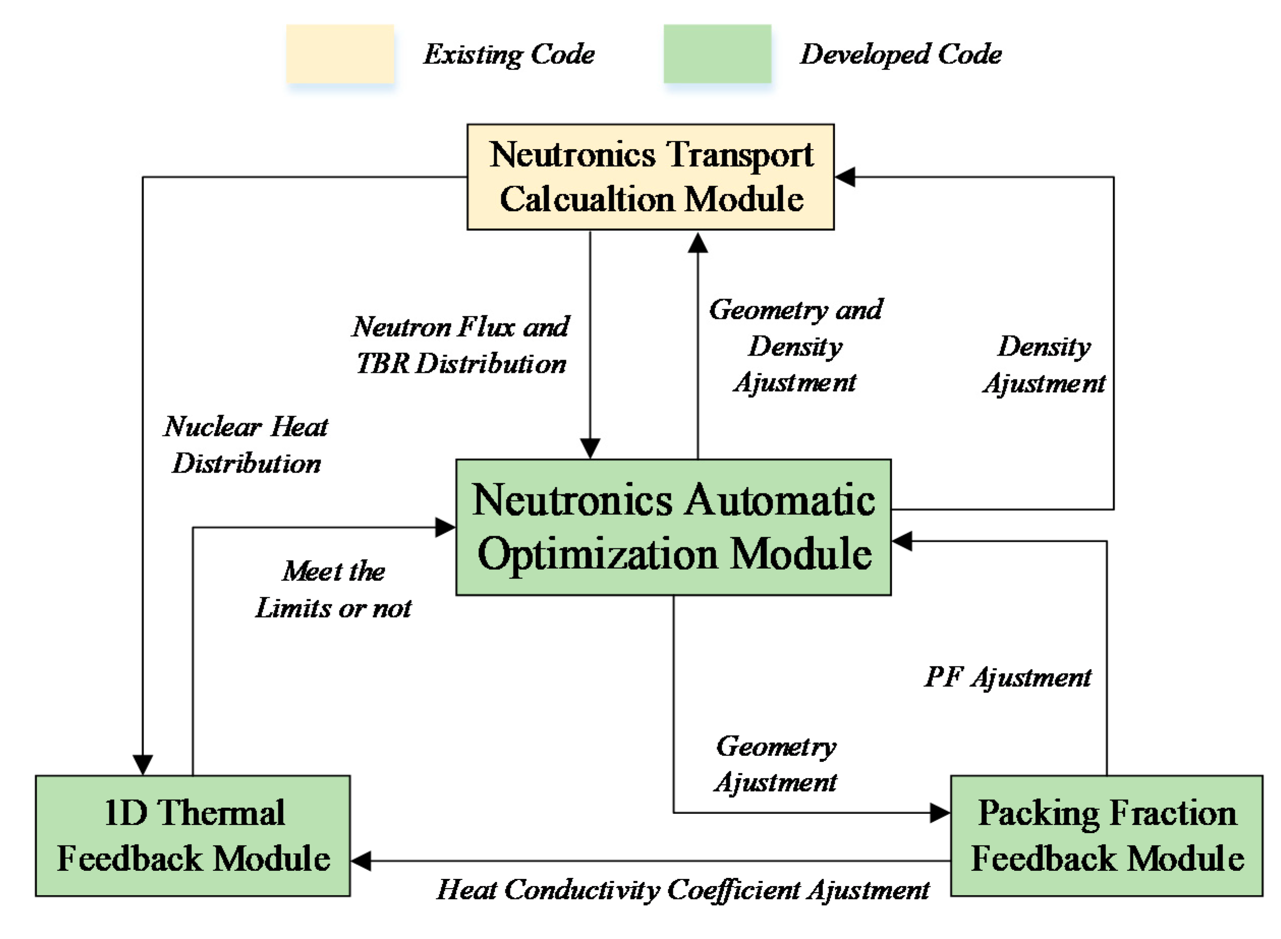
5. Code Development and Verification

5.1. Code Development
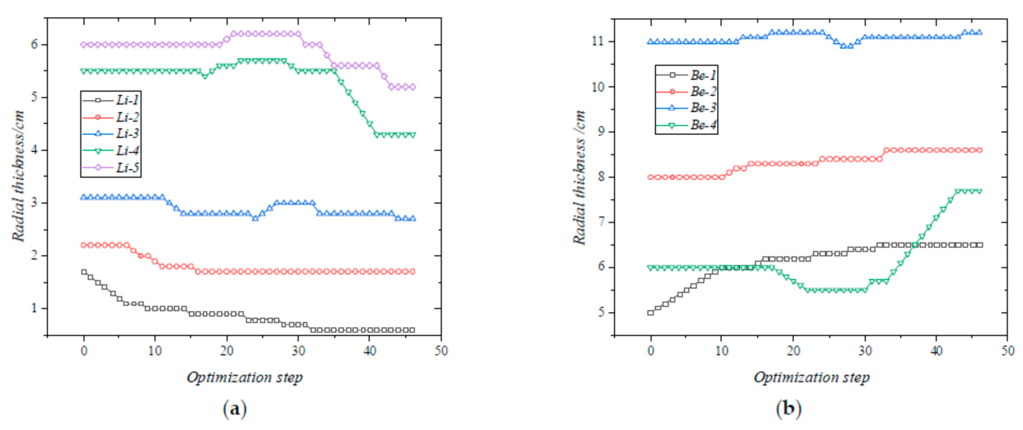
Using programing in Fortran 2013, the multiphysics coupling and neutronics automatic optimization code was developed on Visual Studio 2012. The framework mainly consists of four modules: (1) the neutronic transport calculation module, through which 3D neutronic analysis of the solid breeder TBB was performed; (2) the automatic neutronic optimization module, which holds the direction of the neutronic optimization via calling other modules; (3) the 1D thermal feedback module; (4) the packing fraction feedback module. Among the above four modules, the neutronics transport calculation module was an existing code (MCNP-4C), and the other three modules were self-developed in this paper.
As shown in Figure 10, the flow chart of the multiphysics coupling of the developed code mainly consists of the following five steps. (1) Neutronics transport calculation of solid breeder TBB is performed, nuclear heat distribution obtained and transmitted to the 1D thermal feedback module, and neutron flux and TBR distribution are calculated and transmitted to the neutronics automatic optimization module. (2) Next, 1D thermal calculation of the TBB is performed, and the 1D temperature distribution is obtained. (3) According to the 1D temperature distribution, geometry adjustment is taken by the neutronics automatic optimization module. (4) Then, there is a PF adjustment taken by the PF feedback module, and the geometry and density adjustments for each pebble bed are performed based on the PF adjustment. (5) Neutronics analysis for a new TBB scheme is performed.
A weak multiphysics coupling between neutronics, thermal and PF of pebble beds was primarily achieved. Transmission, iteration and real-time updating of the temperature distribution and density distribution could be realized during the neutronics automatic optimization of the solid breeder TBB in the developed code by coupling the above four modules. The impact of temperature on the cross-sections is not considered in the multiphysics coupling at this stage.

5.2. Verification

The same HCCB TBB typical module shown in Figure 4 is regarded as the object for the verification of the automatic neutronic optimization code. Referring to the latest neutronic design of CFETR phase II, the NWL is 1.69 MW/m2 [11]. The automatic neutronic optimization of the HCCB TBB typical module was performed, and the radial dimensions of the optimized blanket module are listed in Table 2. The variation of the radial thickness of each tritium breeder region and each neutron multiplier are illustrated in Figure 11. The curve of the TBR vs. the optimization step is shown in Figure 12. The 1D radial temperature distribution of the optimized HCCB TBB typical module is shown in Figure 13.
The automatic neutronic optimization results indicate that (1) the optimized scheme can be obtained after 43 steps, and the radial thickness of each region is tending towards stability; (2) the TBR increases from 1.219 to 1.282 (~5.17% improvement) after the automatic optimization, and the maximum temperature of each type of the material is lower than the allowable temperature, as listed as in Table 3.

6. Conclusions

The multiphysics coupling and automatic neutronic optimization code for the tritium breeding blanket of the fusion reactor was developed and verified. This code consists of four modules: the neutronic transport calculation module, the automatic neutronic optimization module, the 1D thermal feedback module and the PF feedback module. The developed 1D thermal feedback module was verified and would be available for real-time temperature monitoring for the TBB. The maximum deviation compared with the 3D results calculated by ANSYS is less than 10K. As for a typical HCCB TBB module, the TBR can increase from 1.219 to 1.282 (~5.17% improvement) after the automatic optimization, and the maximum temperature of each type of the material is lower than the allowable temperature.
A weak multiphysics coupling between neutronics, thermal and PF of pebble beds was primarily achieved in this paper, without considering the impact of temperature on the cross-sections. The nuclear-thermal coupling by means of the Picard method will be mentioned in a future study.

Author Contributions

S.Q.: Methodology, Software, Writing—original draft. Q.C.: Visualization, Supervision. X.D.: Supervision. X.W. (Xueren Wang): Supervision. X.W. (Xiaoyu Wang): Supervision. All authors have read and agreed to the published version of the manuscript.

Funding

The work at SWIP (Southwestern Institute of Physics) is supported under National Natural Science Foundation of China Number 11905046, Talent Project of SWIP Number 202001XWCXRC013 and National Key R&D Program of China Number 2017YFE0300503 and 2017YFE0300601.

Institutional Review Board Statement

Not applicable.

Informed Consent Statement

Not applicable.

Acknowledgments

KIT (Karlsruhe Institute of Technology) for the development of McCAD code.

Conflicts of Interest

The authors declare no conflict of interest.

References

  1. Wan, Y.; Li, J.; Liu, Y.; Wang, X.; Chan, V.; Chen, C.; Duan, X.; Fu, P.; Gao, X.; Feng, K.; et al. Overview of the Present Progress and Activities on the CFETR. Nucl. Fusion 2017, 57, 102009. [Google Scholar] [CrossRef]
  2. Cao, Q.X.; Wang, X.Y.; Wu, X.H.; Yin, M.; Qu, S. Neutronics and Shielding Design of CFETR HCCB Blanket; Nice, France, 2021. [Google Scholar]
  3. Qu, S.; Cao, Q.; Duan, X.; Wang, X.; Li, Z.; Wang, X. Neutronics Effects of Homogeneous Model on Solid Breeder Blanket of CFETR. Fusion Eng. Des. 2020, 160, 111825. [Google Scholar] [CrossRef]
  4. Zhuang, G.; Li, G.; Li, J.; Wan, Y.; Liu, Y.; Wang, X.; Song, Y.; Chan, V.; Yang, Q.; Wan, B.; et al. Progress of the CFETR Design. Nucl. Fusion 2019, 59, 112010. [Google Scholar] [CrossRef]
  5. Thompson. MCNP-A General Monte-Carlo Code for Neutrons and Photon Transport; Springer: Berlin/Heidelberg, Germany, 1985; Volume 240, pp. 33–55. [Google Scholar]
  6. Konno, C.; Ochiai, K.; Wada, M. Analyses of Fusion Integral Benchmark Experiments at JAEA/FNS with FENDL-2.1 and Other Recent Nuclear Data Libraries. Fusion Eng. Des. 2008, 83, 1774–1781. [Google Scholar] [CrossRef]
  7. Wang, X.; Feng, K.; Chen, Y.; Zhang, L.; Feng, Y.; Wu, X.; Liao, H.; Ye, X.; Zhao, F.; Cao, Q.; et al. Current Design and R&D Progress of CN HCCB TBS. Nucl. Fusion 2019, 59. [Google Scholar] [CrossRef]
  8. Wang, X.Y. Development Status of Helium Cooled Ceramic Breeder Tritium Breeding Blanket (HCCB TBB) in China; Budapest, Hungary, 2019. [Google Scholar]
  9. Billone, M.C.; Dienst, W.; Fiament, T.; Lorenzetto, P.; Noda, K.; Roux, N. ITER Solid Breeder Blanket Materials Database; Argonne National Laboratory: Lemont, IL, USA, 1993.
  10. Boccaccini, L.V.; Lulewicz, J.D.; Piazza, G.; Reimann, J.; Roux, N. Ceramic Breeder Pebble Beds for EU HCPB Test Blanket Module; ITER: Saint-Paul-lez-Durance, France, 2001. [Google Scholar]
  11. SDC-IC APPENDIX A: Materials Design Limit Data; ITER: Saint-Paul-lez-Durance, France, 2004.
  12. Boccaccini, L.V. Design Description Document for the European Helium Cooled Pebble Bed (HCPB) Test Blanket Modules; Forschungszentrum Karlsruhe: Karlsruhe, Germany, 2005. [Google Scholar]
  13. Donne, D.M.; Goraieb, A.; Piazza, G.; Sordon, G. Measurements of the effective thermal conductivity of a Li4SiO4 pebble bed. Fusion Eng. Des. 2000, 49–50, 513–519. [Google Scholar] [CrossRef]
  14. Feng, K.M.; Zhang, G.S.; Zheng, G.Y.; Zhao, Z.; Yuan, T.; Li, Z.Q.; Sheng, G.Z.; Pan, C.H. Conceptual design study of fusion DEMO plant at SWIP. Fusion Eng. Des. 2009, 84, 2109–2113. [Google Scholar] [CrossRef]
  15. Wang, S.; Wang, S.; Chen, H. Numerical Influence Analysis of the Packing Structure on Ceramic Breeder Pebble Beds. Fusion Eng. Des. 2019, 140, 41–47. [Google Scholar] [CrossRef]
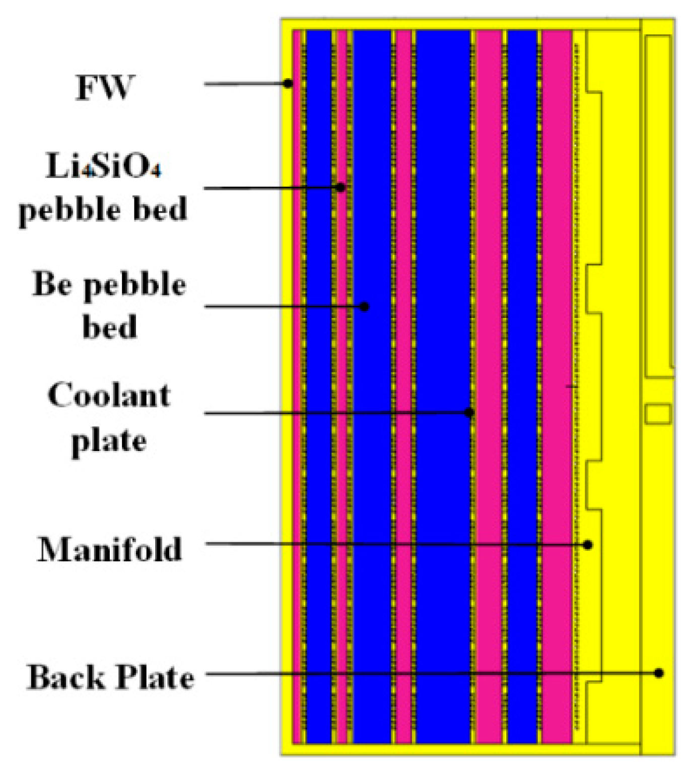
Figure 1. General flow chart of the neutronic optimization for the TBB.
Energies 14 05442 g001
Figure 2. CAD model of the CFETR HCCB blanket typical module.
Energies 14 05442 g002
Figure 3. Simplified model of the TBB with sandwich-like layout for the 1D thermal calculation.
Energies 14 05442 g003
Figure 4. 3D neutronic model of the HCCB TBB [3]. Reproduced from [3], Fusion Engineering and Design: 2020.
Energies 14 05442 g004
Figure 5. 1D average power density distribution of the TBB.
Energies 14 05442 g005
Figure 6. Typical layer model used in ANSYS (a) and the mesh dissection (b).
Energies 14 05442 g006
Figure 7. Verification of 1D thermal feedback module. (a) Result by 1D thermal feedback module; (b) ANSYS result.
Energies 14 05442 g007
Figure 8. The relationship between the packing fraction and container size of the Li4SiO4 pebble beds [15]. Reproduced from [15], Fusion Engineering and Design: 2019.
Energies 14 05442 g008
Figure 9. Flow chart of the automatic neutronic optimization of the TBB.
Energies 14 05442 g009
Figure 10. Flow chart of the multiphysics coupling and neutronic automatic optimization code.
Energies 14 05442 g010
Figure 11. The variation of the radial thickness of each functional region of the HCCB TBB during the optimization. (a) Tritium breeding regions; (b) neutron multiplier regions.
Energies 14 05442 g011
Figure 12. Curve of the TBR vs. the optimization step of the HCCB TBB.
Energies 14 05442 g012
Figure 13. Radial temperature distribution of the HCCB TBB.
Energies 14 05442 g013
Table 1. The initial radial dimensions of the blanket module.
StructureRadial Length/cmStructureRadial Length/cm
FW2.5CP-51.0
Li4SiO4-11.7Be-311.0
CP-11.0CP-61.0
Be-15.0Li4SiO4-45.5
CP-21.0CP-71.0
Li4SiO4-22.2Be-46.0
CP-31.0CP-81.0
Be-28.0Li4SiO4-56.0
CP-41.0Manifold14.0
Li4SiO4-33.1Back plate1.0
Table 2. The radial dimensions of the optimized blanket module.
StructureRadial Length/cmStructureRadial Length/cm
FW2.5CP-51.0
Li4SiO4-10.6Be-311.2
CP-11.0CP-61.0
Be-16.5Li4SiO4-44.3
CP-21.0CP-71.0
Li4SiO4-21.7Be-47.7
CP-31.0CP-81.0
Be-28.6Li4SiO4-55.2
CP-41.0Manifold14.0
Li4SiO4-32.7Back plate1.0
Table 3. The limit temperatures of each type of the materials in the TBB [14]. Reproduced from [14], Fusion Engineering and Design: 2009.
MaterialMax Temperature/KLimit Temperature/K
Li4SiO410641173
Be763923
ODS steel758923
Publisher’s Note: MDPI stays neutral with regard to jurisdictional claims in published maps and institutional affiliations.

