Article

Effects of Bypass Flow Distribution on Cold Flow Characteristics of Integrated Afterburner

1
College of Energy and Power Engineering, Nanjing University of Aeronautics and Astronautics, Nanjing 210016, China
2
Shenyang Engine Research Institute, Aero Engine Corporation of China, Shenyang 110015, China
*
Author to whom correspondence should be addressed.
Energies 2021, 14(18), 5842; https://doi.org/10.3390/en14185842
Submission received: 14 August 2021 / Revised: 10 September 2021 / Accepted: 13 September 2021 / Published: 15 September 2021

Abstract

:
Integrated design is a trend in the development of afterburners, and the distribution of cold flow is directly related to their flow field characteristics, combustion organization, and the cooling effect of components. Numerical simulations were performed to illustrate the effects of bypass flow distribution on the flow distribution, mixing characteristics, and cooling efficiency of the components by varying the cooling flow path structure parameters. Within the range of parameters in this study, it can be indicated that with the increase of heat shield inlet height and afterburner annulus height, the total pressure recovery coefficient along the path increased accordingly, and the increasing rate at the afterburner outlet is 1.12% and 1.19%, respectively. The average cooling efficiency of radial flameholder, circumferential flameholder, and fuel injector all decrease, but the rate of decrease varies slightly depending on the location of the components. The increase of heat shield inlet height would reduce thermal mixing efficiency by approximately 5.4% at the afterburner outlet, and the increase of afterburner annular height would increase about 2.9%.

1. Introduction

Afterburners are widely used in advanced aero engines in order to meet operational needs. Afterburners increase the maneuverability of aircraft by increasing the thrust of engines in a short period of time at the cost of a higher fuel consumption rate [1]. With the development of aero-engines, afterburner technology is in continuous pursuit of higher combustion efficiency and stability, lower fluid loss, and lighter structural quality [2]. It has been gradually difficult for the traditional afterburner to meet design requirements owing to the inherent defects arising from its structural characteristics [3]. Therefore, the concept of integrated design of components in the afterburner has become an essential development direction.
The scheme of an integrated afterburner was first proposed by Clements et al. [4] in which the flow pate, flameholder, and fuel injector were integrated. This made it possible to decrease the length, reduce the total pressure loss, and improve the reliability of the afterburner. Subsequently, Lovett et al. [5] analyzed the combustion characteristics of the afterburner under high-speed conditions and theoretically discussed the technical characteristics as well as the constraints of the integrated scheme. Raffoul et al. [6] adopted the Reynolds time-averaged equation and large eddy simulation to numerically compute the integrated afterburner, respectively. Mean velocities, turbulent fluctuations, and probability density functions (PDFs) were compared to the experimental data. The conclusions were drawn that the adoption of large eddy simulation has a slight advantage in obtaining transient characteristics, but the Reynolds time-averaged equation is well adapted in terms of computational scale. By conducting a three-dimensional steady-state numerical calculation on an integrated structure, Ebrahimi et al. [7] obtained the flow distribution and temperature distribution along the axial direction in the afterburning state, which provided a reference for further research. Shahnam et al. [8] conducted an experimental study of the integrated afterburner and concluded that the position and flow rate of primary and secondary fuel injectors could effectively adjust the combustion characteristics and ensure combustion stability, which proved the feasibility of the integrated scheme. Zhang et al. [9] studied the approach of ignition and flame stabilization in a wide range of integrated afterburners by means of experimental and numerical methods. Huang et al. [10] adopted six non-uniform inlet velocity profiles with different velocity peak positions and values to study the effects on the flame stability limits and combustion efficiency of the afterburner via an experimental method. The effects of aero thermodynamic factors on the performance of afterburners were studied by comparing and analyzing characteristics of a low bypass ratio turbofan engine at various flight conditions [11,12]. A new method using a plasma jet igniter was developed and applied in the integrated afterburner by Fei et al. [13] to reduce ignition delay time and achieve stable combustion. In addition, adopting new stabilization structures, such as the cavity flameholder instead of the traditional bluff-body flameholder, has also become one of the research directions concerning the integrated afterburner in recent years [14,15,16]. The cavity flameholder is based on the mechanism of the trapped vortex and is more appropriate for high-speed conditions [17]. However, since the operation mode of cavity flameholder is fundamentally different from that of conventional structures, it still needs further research and exploration if widely used [18,19].
As the temperature of the afterburner inlet gets higher, the wall temperature of the components can be more likely to exceed the limit of materials. This may lead to the distortion and ablation of the structures in contact with high-temperature gas at the afterburning condition. Therefore, the effective cooling of high-temperature structural components to ensure stability and reliability is particularly critical. Many studies have explored and optimized the cooling methods and structures of various components in the afterburner. Abreau et al. [20] proposed an integrated structure in which the flameholder was protected by the bypass flow into it and the film cooling formed on its surface. Woltmann et al. [21] tried to set the fuel injectors in the flameholder to avoid ablation of the structure and reduce flow loss. Lubarsky et al. [22] designed a structure that integrated injection, cooling, and stabilization. In this structure, high-temperature gas entered through the hole opened in the front edge of flameholders to atomize the fuel, and low-temperature airflow flew through the cooling channel at the bottom of it to avoid ablation. Research on the cooling characteristics of the ripple heat shield has also been conducted in [23,24,25]. Although the cooling of each individual high-temperature component in the afterburner has been well studied, there is a relative lack of research on the bypass flow distribution. It is not only directly related to the cooling performance of the components, but also influences the flow and mixing characteristics of the integrated afterburner to some extent. In consideration of the fact that the proper bypass flow distribution is a requisite for the stability and reliability of each component, further research is necessary. In this paper, the rate of bypass flow into each component of the integrated afterburner is varied by changing the cooling flow path structure parameters with the boundary conditions remaining unchanged. The effects on the flow and mixing characteristics of the integrated afterburner and cooling efficiency of the components are to be comprehensively explored.

2. Numerical Method

2.1. Geometric Model

Figure 1 depicts the physical model of the integrated afterburner. It was composed of the inner cone, a shunt ring, the radial flameholder, the circumferential flameholder, the fuel injector, the heat shield, etc. The long radial flameholder and the short one were evenly and alternately distributed in the circumferential direction.
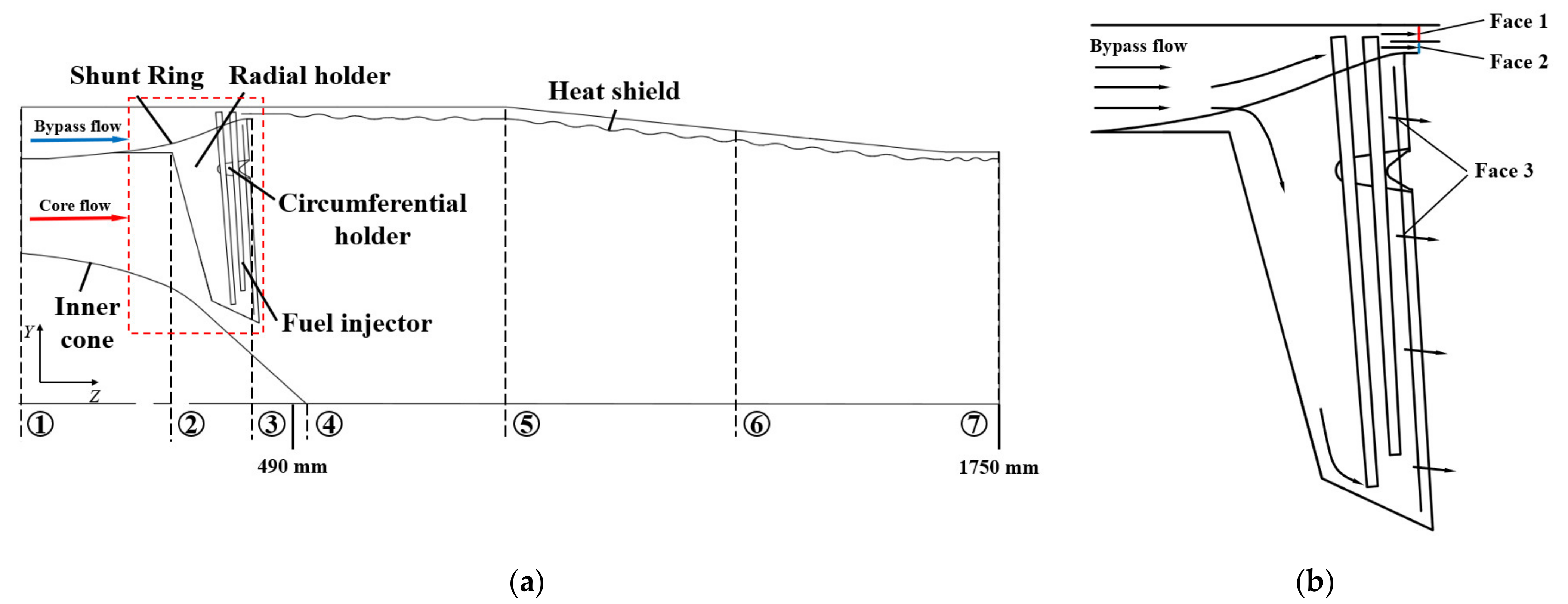
The layout of the structure inside the integrated afterburner is shown in Figure 2a, which is characterized by the integration of the diffuser and radial flameholder. Radial flameholder was located in the expansion channel formed by the shunt ring and inner cone, and its effects in the integrated afterburner were complicated. On the one hand, the direction of core flow in the integrated afterburner would be changed into the axial one. On the other hand, core flow formed a stable recirculation zone downstream of radial flameholder after undergoing the process of deceleration and expansion, which facilitated the organization of combustion. Radial flameholders and the adjacent circumferential ones together played a role in stabilizing and propagating flame, and the blockage ratio ε was about 0.275.
The partially enlarged view of the radial flameholder is shown in Figure 2b. The hollow structure inside both radial flameholders and circumferential ones allowed the cold bypass flow to enter them for cooling the high-temperature parts. Fuel injectors were arranged in the chamber of the radial flameholder to reduce the flow loss caused by exposure to core flow. Meanwhile, it would prevent fuel coke and ablation under the action of the cold bypass flow. The cooling flow outlets were placed both at the rear wall of radial flameholders and circumferential flameholders. They allowed bypass flow to further mix with core flow in the afterburner. The longitudinal ripple heat shield was located between the afterburner and shell with dense film cooling holes arranged downstream of the wave trough.
In order to facilitate the following analysis, Figure 2a marks seven typical cross-sections along the flow path in the afterburner, with section 1 at the afterburner inlet, section 2 at the contact position of core flow and radial flameholder, section 3 at the end of shunt ring, section 4 at the trailing edge of the inner cone, section 5 at the start of contraction of afterburner, section 6 at the middle position of afterburner, and section 7 at the afterburner outlet.
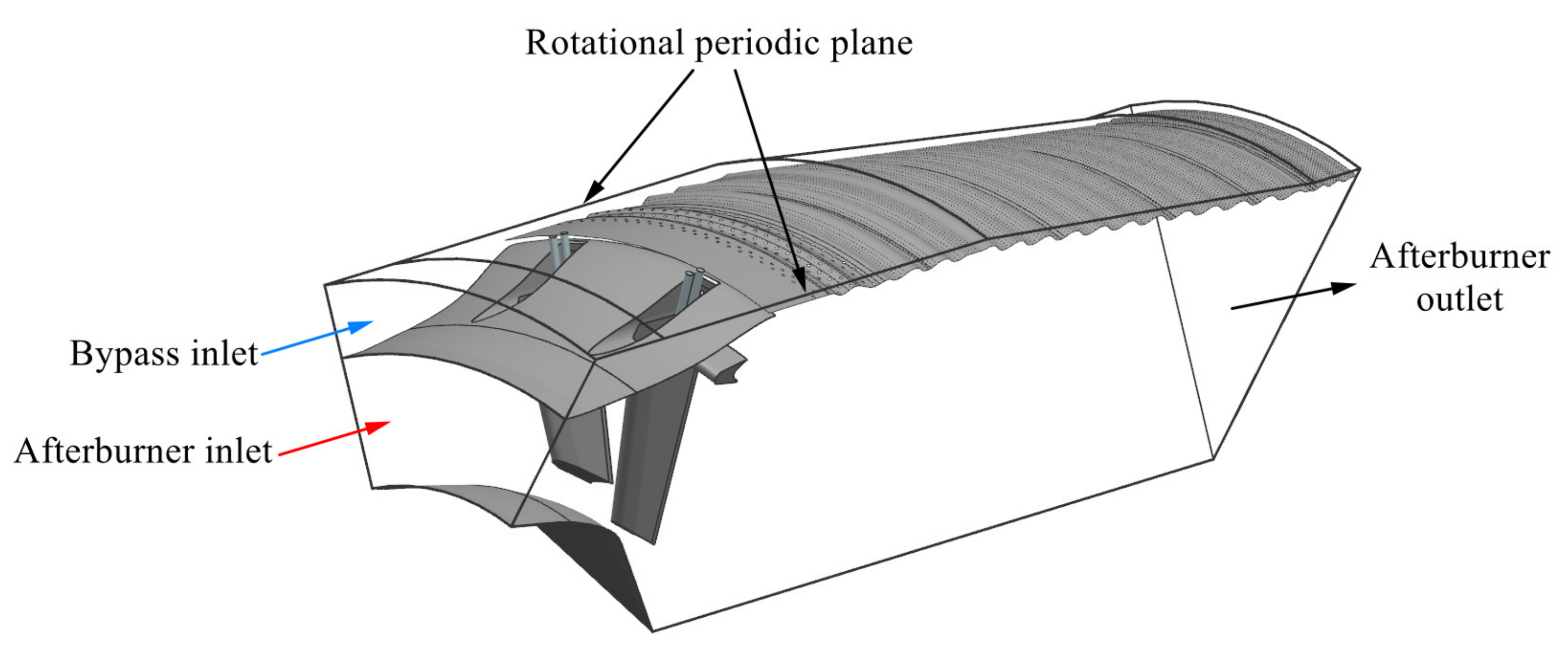
Since the 3-D structure of the integrated afterburner was characterized by periodic rotational symmetry, the 1/8 model was selected as the research object. As shown in Figure 3, the computational domain included two complete radial flameholders and part of the remaining components with both side walls adopting rotational periodic boundary conditions.
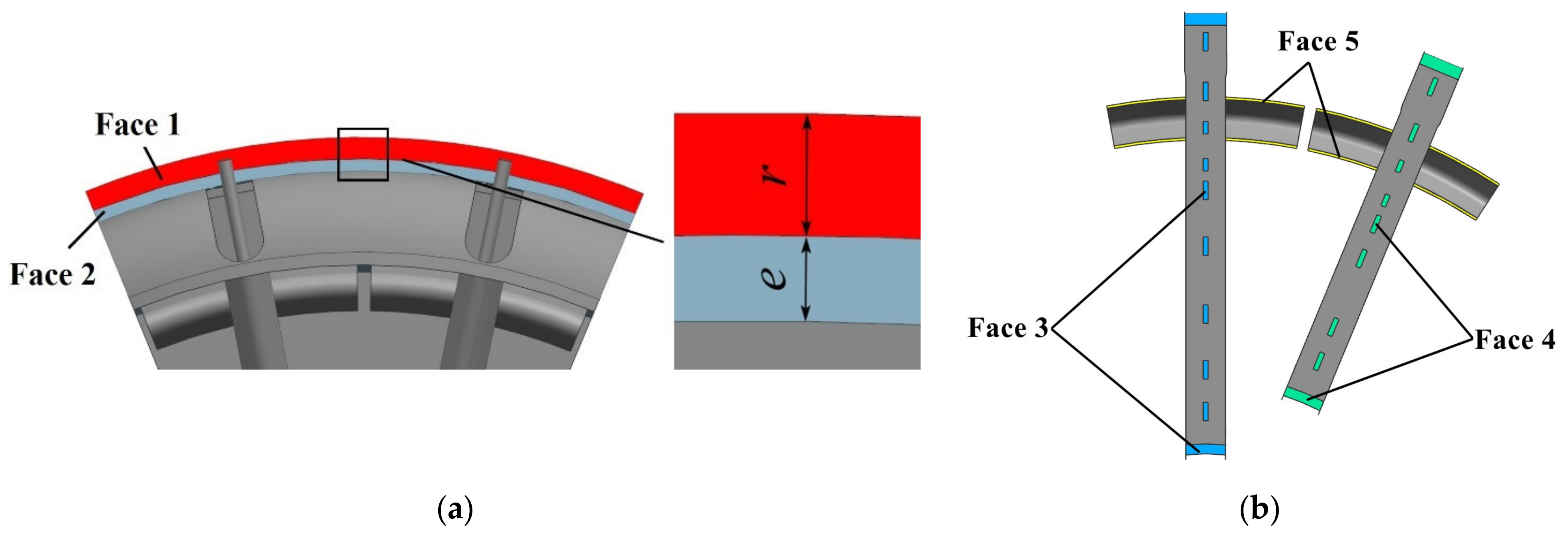
In order to discuss the distribution of bypass flow, several slits or annulus were selected as the feature faces to monitor the mass flow rate. As shown in Figure 4, this included the heat shield inlet, the afterburner annulus located at the end of the shunt ring which connecting the bypass channel to the afterburner, the outlet of long radial flameholder, the outlet of short radial flameholder, and the outlet of circumferential flameholder, which were respectively referred to as Face 1 to Face 5.
As part of the design process, the importance of bypass flow distribution to the cooling performance of the components could not be more emphasized. Moreover, the change of it would also have a significant impact on the overall flow characteristics and mixing performance of the integrated afterburner. Therefore, a comprehensive analysis and assessment of its impact are required. In this paper, the radial height r of heat shield inlet (Face 1) and the radial height e of afterburner annulus (Face 2) were respectively changed so as to investigate the effect of bypass flow distribution on the performance of integrated afterburner. The baseline model was characterized by the structure with r = 12.5 mm and e = 8.5 mm. Under the conditions in which the rest geometric parameters remain unchanged, the models consisting of different cooling flow path structure parameters were obtained by increasing the heat shield inlet height r and the afterburner annulus height e by 1 mm, 3 mm, and 5 mm, respectively. The above models were named according to the combination of the heat shield inlet height r and the afterburner annulus height e of the integrated afterburner. For example, r4e1 indicated the model characterized by r = 17.5 mm and e = 8.5 mm. The specific structure values of each model are shown in Table 1.
In the computational domain, the corresponding boundary conditions were given as follows. The afterburner and bypass inlet were both treated as the mass-flow inlet, and the non-dimensionalized mass flow rate, total pressure, and total temperature are shown in Table 2. A turbulence intensity of 5% was specified as inlet condition referring to the realistic engine conditions, following the results obtained by Singh K et al. [26]. While the static pressure at the afterburner outlet was uncertain, a Laval nozzle in the complete expansion state was connected to the afterburner (the nozzle structure was not shown in the schematic diagram of the computational domain). The outlet boundary of the nozzle was defined as a pressure outlet with zero gauge pressure. The no-slip condition was imposed at the solid surfaces of the model.

2.2. Selection of the Turbulence Model

To verify the accuracy of the current numerical method, different two-equation turbulence models were selected to perform numerical simulations under experimental conditions based on [27]. The experimental model, whose mechanism is relatively similar to the model in this paper, consisted of a single ring V-gutter with twelve outer and six inner radial V-gutters. The outer radial V-gutters faced the bypass stream, and the inner ones faced the core stream. The experiment was conducted in a wind tunnel in which the mass flow rate of the inlet was 0.35 kg/s, the mean velocity was 9.81 m/s, and the Reynolds number was 1.3 × 10⁵. The only difference in the grids between various turbulence models is the way of generating the boundary layer near V-gutters to cater for the required Y-plus value.
Figure 5 illustrates numerical and experimental results of the non-dimensionalized axial velocity distribution along the radial direction in the characteristic section downstream of the radial flameholder. The results of several turbulence models were in agreement with the experimental data, among which the standard k-ε model results stood out due to the small relative error. Since the standard k-ε turbulence model has been validated in quite a few studies to be the reasonable choice in afterburner simulations [28,29,30], it was adopted for the present turbulence calculation.
All simulations were carried out using the Fluent pressure-based solver. The steady-state simulation was based on a three-dimensional compressible Reynolds-averaged Navier–Stokes equation. The working fluid was treated as ideal gas. The viscosity was determined in terms of the Sutherland formula, and the thermal conductivity was determined using the kinetic theory. The discrete ordinates model was adopted for radiation calculation without considering gas absorption and scattering. The number of both theta and phi divisions was set as 2 to describe the non-uniformity of temperature on space, and the internal emissivity of the walls was treated as 0.8. The governing equations were discretized by a second-order upwind interpolation scheme. Pressure-velocity coupling was based on the SIMPLE algorithm. The solutions were considered converged when the RMS values of all the equations fell lower than 10−5.

2.3. Grid Independence

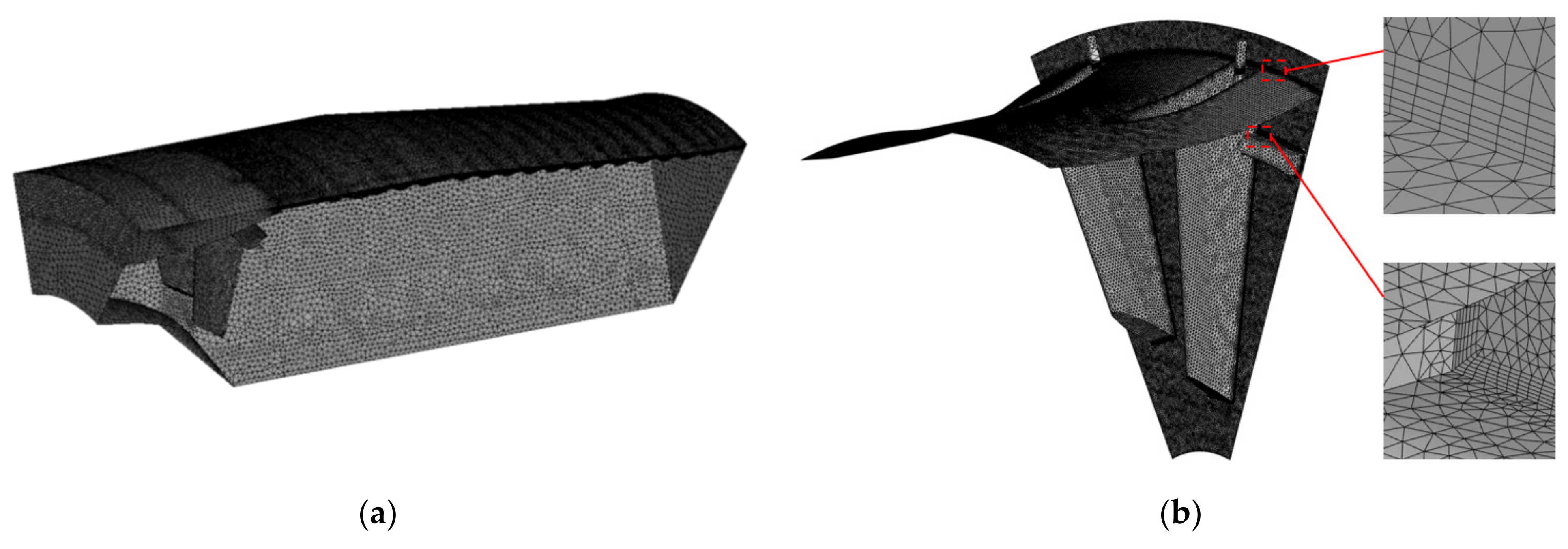
Due to the complexity and 3D asymmetry of the computational domain structure, unstructured grids were generated using ICEM-CFD, as shown in Figure 6. The triangular element was used to mesh the complex structure of the flameholder, and the tetrahedral element was grown from its surface onto the adjacent region. The maximum size of the grid near the flameholder and heat shield was 2 mm and 1.7 mm, respectively. A slightly coarser grid was applied for the region downstream of the flameholder to the afterburner outlet, and the maximum size was 10 mm. The six-layered prism was used for the flameholder and shunt ring in order to capture the flow field and heat transfer near the wall and to ensure y+ = 35–80.
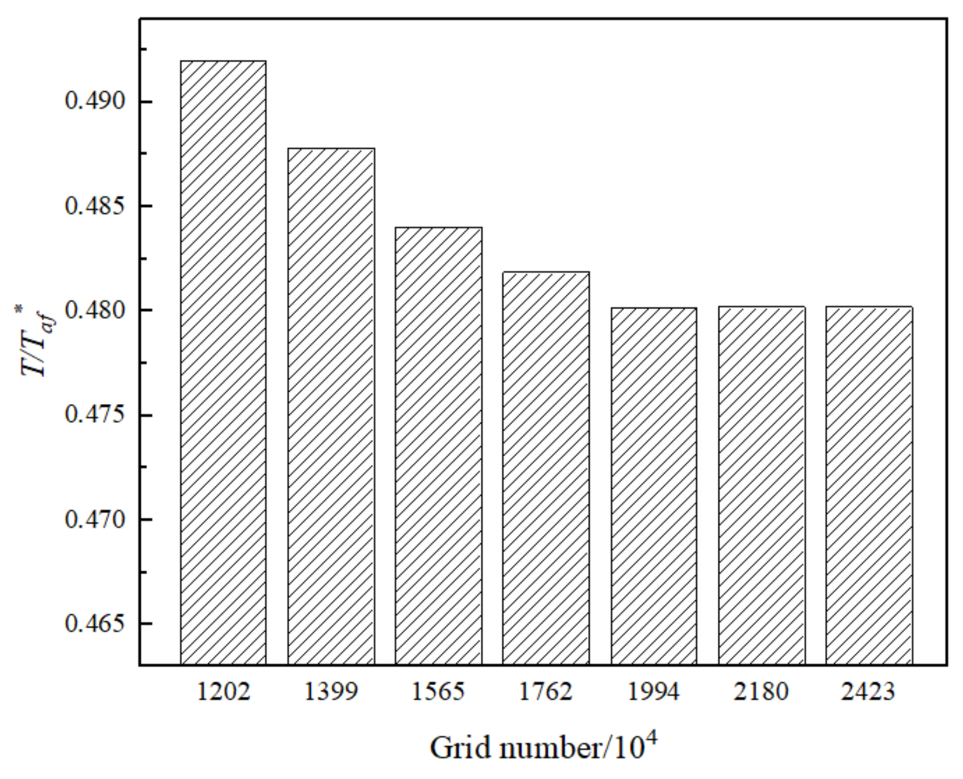
The validation of grid independence was performed in the baseline model for appropriate computational scale and accuracy. Figure 7 illustrates the variation of the non-dimensionalized average temperature of the heat shield with the number of grids. It can be identified that calculation results tend to stabilize with the change of grid numbers when it was close to 1,944,000 cells. Therefore, the grid system was used for the following computations.

3. Results and Analysis

3.1. Flow Characteristics in Afterburner and Bypass Flow Distribution

Bypass flow was divided into three parts according to its flow path. The first part entered the heat shield channel through Face 1 and formed film cooling for thermal insulation. The second part flew through the afterburner annulus (Face 2) to mix with the core flow directly. The last one went into the internal structure of flameholders for cooling components and flew out through the outlet (Face 3–5) for further mixing.
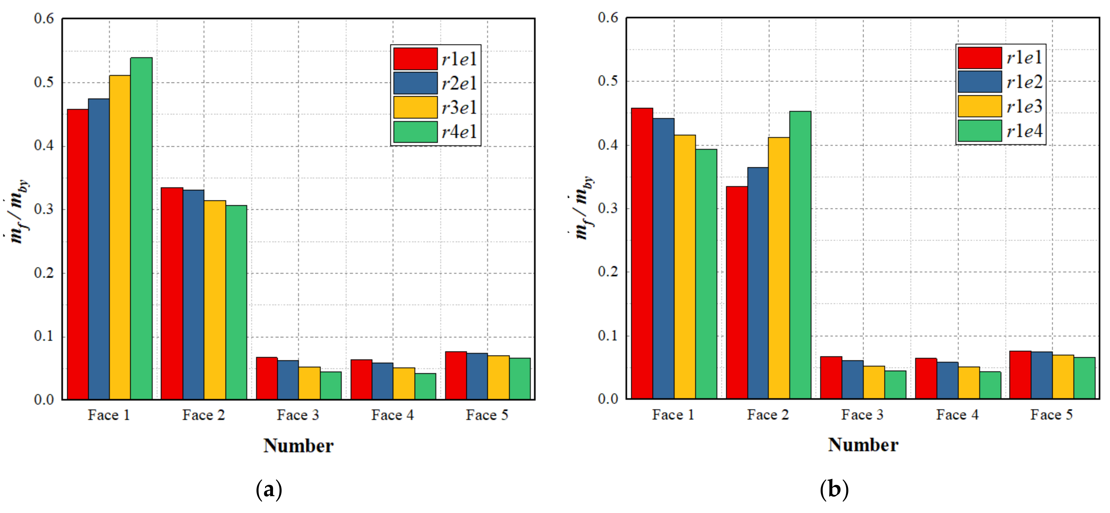
The results of bypass flow distribution under cases of different cooling flow path structure parameters are shown in Figure 8. Most of the bypass flow flew into the heat shield channel or afterburner through Face 1 and Face 2, while only a small part entered flameholders for cooling. The above phenomenon tended to be more evident with the increase of heat shield inlet height r and afterburner annulus height e.
Figure 8a depicts the phenomenon as follows: As heat shield inlet height r increased, the mass flow rate through the corresponding characteristic faces (Face 1) rose accordingly, while the ratio of the flow through the remaining faces (Face 2–5) would fall. Compared to the baseline model, the mass flow rate into the heat shield channel increased by 17.7%. For bypass flow which flew into the afterburner directly and entered flameholders for cooling, the decreasing rate was 8.4% and 26.1%, respectively. Similar conclusions can be drawn from Figure 8b for the variation in afterburner annulus height e, with a 14.2% decrease in the flow rate through Face 1, a 35.2% increase in the flow rate through Face 2, and a 25.6% decrease in the flow rate through Face 3–5.
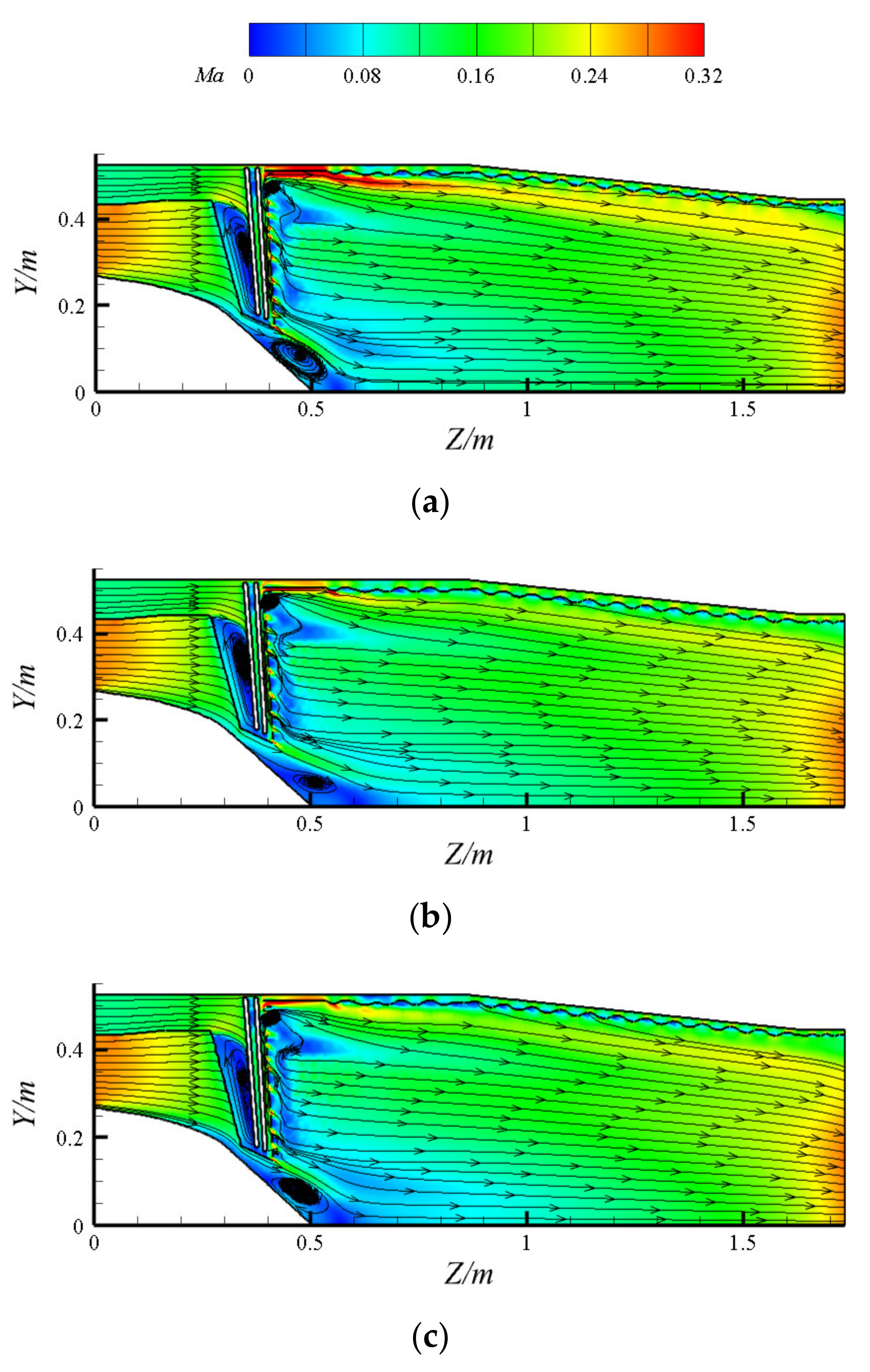
Streamline and velocity distribution on the symmetry plane of integrated afterburner with different cooling flow path structure parameters are shown in Figure 9. It can be seen that the flow characteristics of the afterburner are insensitive to changes in cooling flow path structure parameters. Part of the core flow formed a recirculation zone downstream of radial flameholders after the process of deceleration and expansion, while the other part separated under the effect of adverse pressure gradient when flowing through the surface of the inner cone and thus formed a separation zone at its trailing edge. The bypass flow also formed a separation zone that filled the entire chamber at the front edge of the internal chamber as it entered the radial flameholder. Due to the fact that the simulations were performed under a high bypass ratio condition, the bypass flow path was congested for the baseline model. As a result, the Mach number of bypass flow could be relatively high when passing through heat shield inlet and afterburner annulus. It had an obvious influence on the velocity distribution downstream of the corresponding faces within a distance. The phenomenon was greatly relieved by the increase in cooling flow path structure parameters, and the Mach number of each feature face and their downstream region presented a falling trend.

3.2. Velocity Distribution of Heat Shield Inlet

The cooling effect of the heat shield is closely related to the uniformity of velocity distribution at its inlet. Uneven inlet velocity distribution may lead to an inadequate cooling effect in part of the heat shield, thus resulting in higher thermal stress on its surface, which may lead to structural distortion. As shown in Figure 10, the heat shield inlet was divided equally into 14 parts along the circumference in order to evaluate the uniformity of inlet velocity distribution, and the characteristic velocity coefficient v x * (x = 1–14) can be expressed as:
v x * = v x d m . x 1 n 1 n v x d m x .
where v x is the velocity of heat shield inlet.
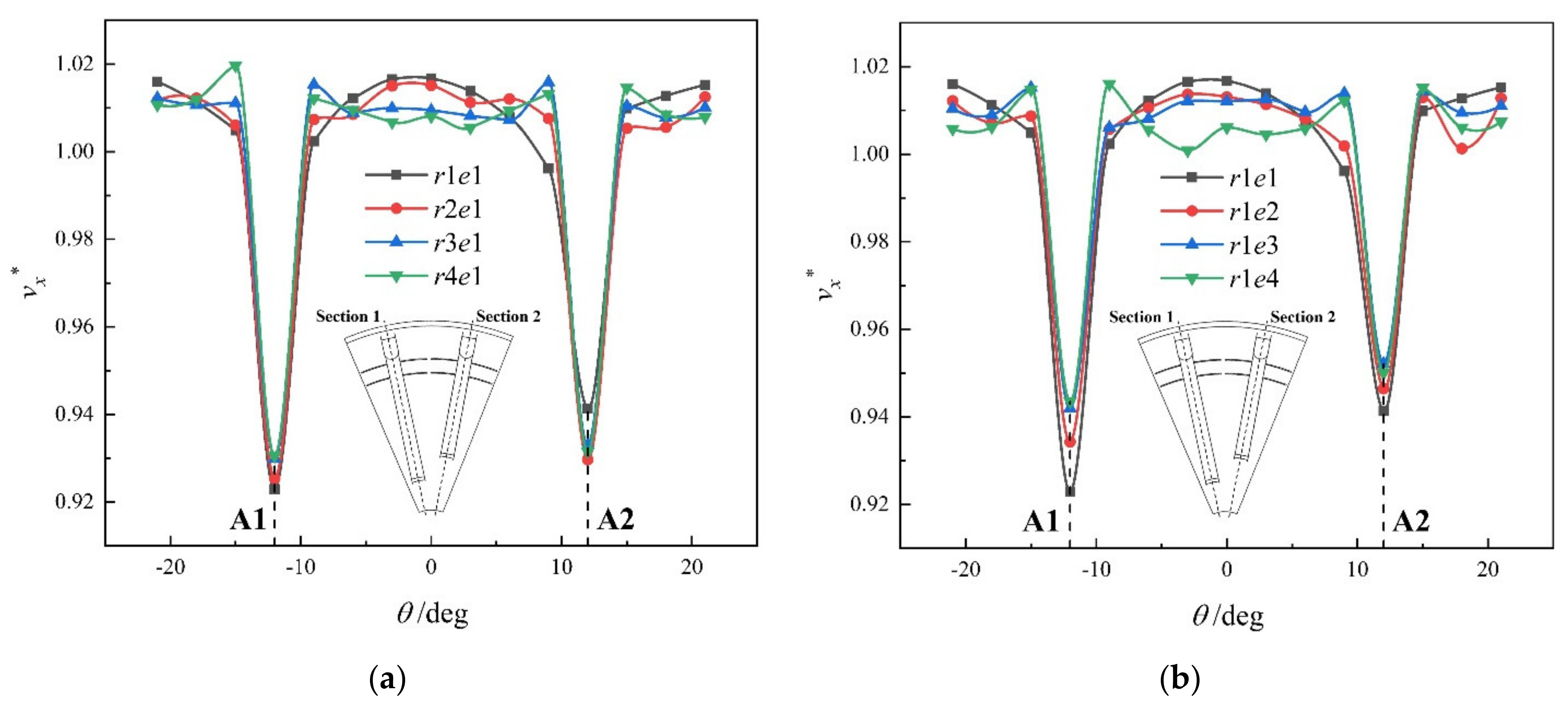
Figure 11 illustrates the effects of cooling flow path structure parameters on the velocity coefficient distribution along the circumferential angle of the heat shield inlet. For the sake of discussion, the part of the heat shield inlet corresponding to the central section of the long radial flameholder (Central section 1) and that of the short flameholder (Central section 2) were referred to as the A1 and A2 regions, respectively. It can be seen that, for one certain model, the velocity coefficient distribution was rather uniform along the circumferential direction and basically symmetric on θ = 0°. However, the phenomenon of local depression appeared in the A1, A2, and the adjacent regions, and the velocity coefficient of the A1 region was lower than that of the A2 region. The reason could be explained as follows. Upstream of these regions, part of the cold flow was diverted due to the presence of radial flameholder, which caused less bypass flow to eventually path through these regions. As a result, the velocity coefficient of these regions could be significantly low, and the velocity coefficients of the A1 and A2 regions would be slightly different since the flow rate into the long radial flameholder was slightly higher than that of the short one.
As heat shield inlet height r and afterburner annulus height e increased, the velocity coefficients of the A1 and A2 region became closer because the gap between the flow rate into the long and short flameholder decreased. However, the overall velocity coefficient distribution did not vary in the same pattern with both. For the heat shield inlet height r, although the increase of this parameter reduced the flow rate into flameholders, it increased the affected area simultaneously. Under the comprehensive effect of both, the velocity distribution of the heat shield inlet did not improve significantly. Moreover, the area of the heat shield inlet did not change with the increase of afterburner annulus height e, which meant that the heat shield inlet velocity distribution was mainly influenced by bypass flow distribution at this time. Since the flow into flameholders consequently decreased, there was a significant increase in its velocity uniformity with the increase of e.

3.3. Total Pressure Recovery Coefficient

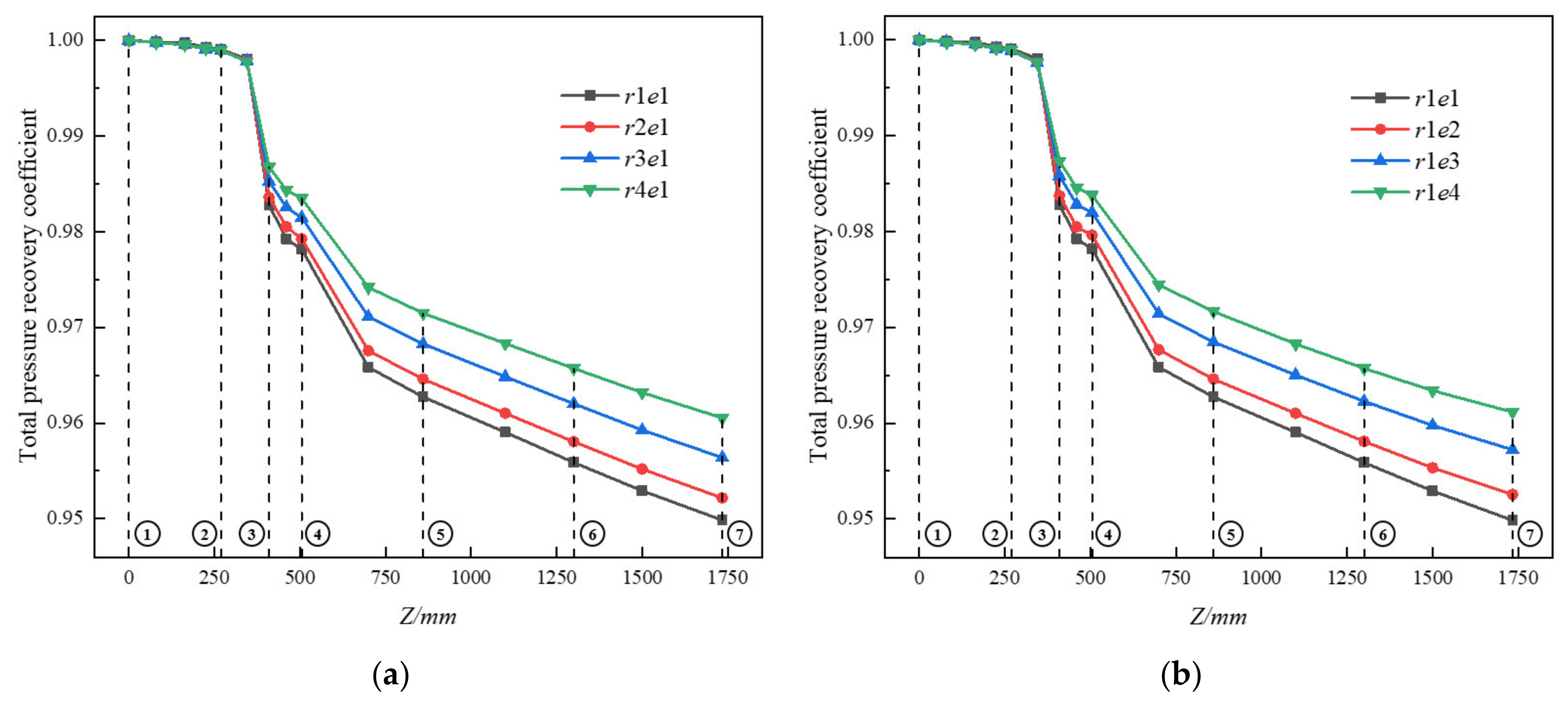
Total pressure recovery coefficient is one of the important parameters to measure the flow performance of the integrated afterburner. In this paper, the above typical sections in Figure 2a were selected to investigate the influence of cooling flow path structure parameters on the distribution of total pressure recovery coefficient along the flow path. Total pressure recovery coefficient ( σ ) is defined as:
σ = P r * d m . r / P a f * d m . a f + P b y * d m . b y
where P a f * is the total pressure of afterburner inlet, P b y * is the total pressure of bypass inlet, and P r * is total pressure in the reference section.
Total pressure recovery coefficient along the flow path under cases with different cooling flow path parameters is shown in Figure 12. As listed in Table 3, during the flow and mixing process of core flow and bypass flow, there were several types of total pressure loss as follows:
From section 1 to 3, the loss mainly included the diffusion loss generated by core flow in the expansion channel, the friction loss caused by core flow and bypass flow through walls, and the local loss due to the sudden expansion of flow path when bypass flow entered flameholders and the sudden contraction when core flow passed through flameholders. From section 3 to 5, the loss was mainly attributed to the mixing of core flow and bypass flow, including the process respectively dominated by longitudinal vortex downstream of the radial flameholder and the free shear between core flow and bypass flow after vortex shedding and dissipation. From section 5 to 7, the loss was mainly due to the contraction of the middle to the outlet of the integrated afterburner.
It could be seen from Figure 12 that the total pressure recovery coefficient along the flow path rose significantly with the increase of the heat shield inlet height r and the afterburner annulus height e. The impact was more obvious at the trailing edge of the shunt ring (section 2–3) and at the downstream of flameholders (section 4–5).
As the heat shield inlet height r increased, the diffusion channel area of core flow decreases, resulting in a reduction of diffusion loss. In addition, the velocity of bypass flow decreased so that the friction loss would also reduce. Therefore, the total pressure recovery coefficient of the corresponding region (section 2–3) increased significantly for those reasons, and the extent of the variation caused by this phase accounted for about 38.8% of the total one. For the region downstream of flameholders (section 4–5), since the velocity of bypass flow decreased, the mixing loss caused by free shear between core and bypass flow would be lower, and the magnitude of the variation caused by this phase accounted for almost 34.5%. Under the influence of the above factors, the total pressure recovery coefficient at the afterburner outlet increased by nearly 1.12% with the increase of the heat shield inlet height r. The reason for the change of the total pressure recovery coefficient with the afterburner annulus inlet e was basically the same as above. The extent of the variation was 41.9% at the trailing edge of the shunt ring and 32.2% downstream of the flameholders. The total pressure recovery coefficient at the afterburner outlet increased by nearly 1.19% with the increase of the afterburner annulus height e.

3.4. Thermal Mixing Efficiency

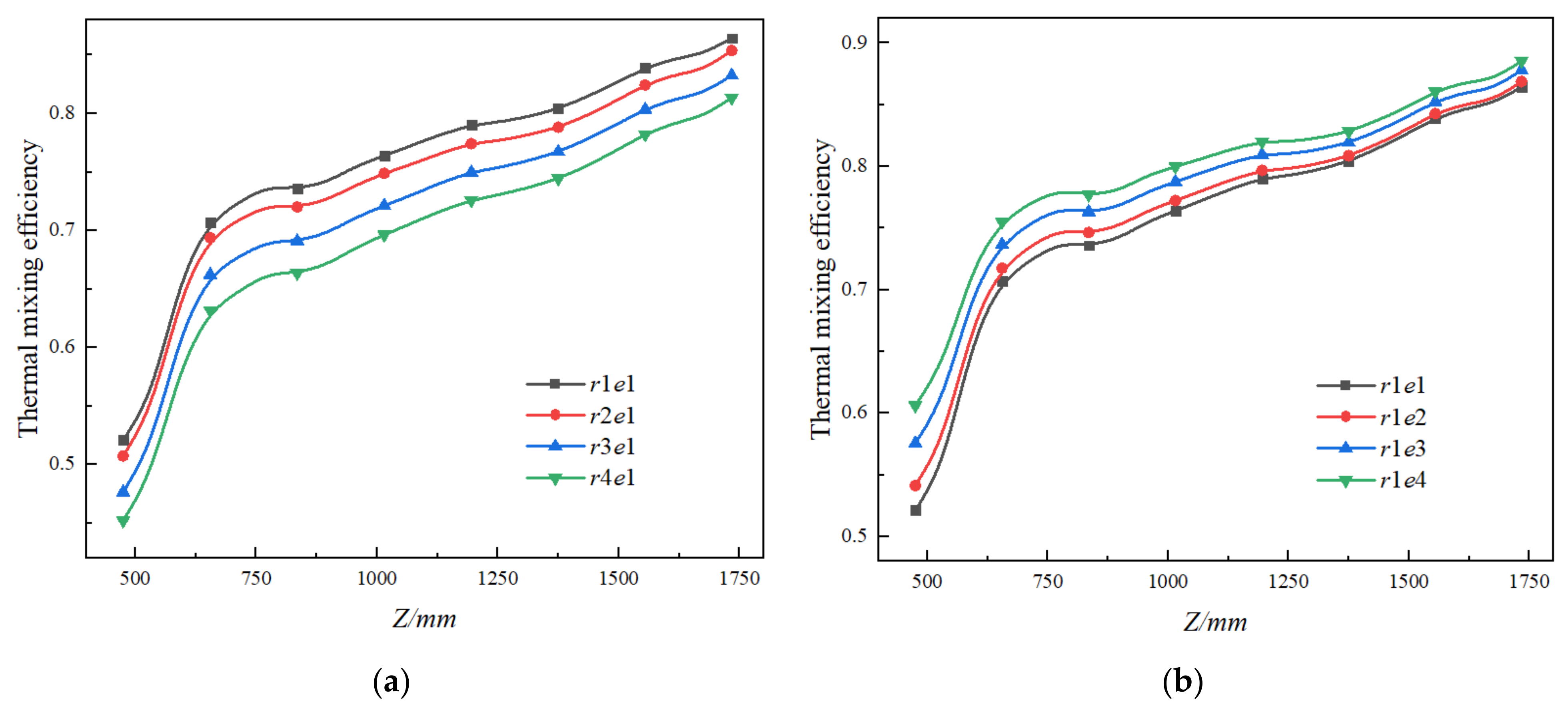
The shunt ring functioned as a splitter mixer in the integrated afterburner. To evaluate the mixing characteristics of core and bypass flow in the integrated afterburner, the concept of thermal mixing efficiency ( η t ) [31] is adopted and given as:
η t = 1 T T mix 2 d m . T af 2 m . af + T by 2 m . by T mix 2 m . af + m . by
where Taf is the temperature of airflow at afterburner inlet, Tby is the temperature of airflow at bypass inlet, m . af is the mass flow rate of airflow at afterburner inlet, m . by is the mass flow rate of airflow at bypass inlet, and Tmix is the temperature of the airflow after complete mixing.
Thermal mixing efficiency downstream of the shunt ring along the flow path under cases with different cooling flow path parameters is shown in Figure 13. The range of the distribution of thermal mixing efficiency is marked in Figure 2a. The variation of thermal mixing efficiency along the flow path was mainly influenced by the mixing method of core flow and bypass flow. The bypass flow downstream the trailing edge of the shunt ring was fully mixed under the dominant action of the longitudinal vortex, so the thermal mixing efficiency increased sharply in this stage during this period. Moreover, with the shedding and dissipation of the longitudinal vortex, bypass and core flow mainly relied on the viscous interaction between them for free shearing, and the increasing rate of thermal mixing efficiency slightly slowed down.
Comparing Figure 13a and Figure 13b, it can be found that the effects of heat shield inlet height and afterburner annulus height on the thermal mixing efficiency along the flow path differed. Thermal mixing efficiency would decrease with the increase of heat shield inlet height, and the opposite conclusion could be drawn for afterburner annulus height. This could be attributed to the change in bypass flow distribution. The increase in heat shield inlet height resulted in a reduction in the mass flow rate of both the bypass flow directly into the afterburner through Face 2 and that flew through Face 3–5 after cooling flameholders. The overall decreasing rate was approximately 15.1%, which meant that the flow rate for mixing with core flow decreases, resulting in the decreased strength of the longitudinal vortex. Therefore, the temperature distribution in each characteristic section was more uneven, and the mixing degree of flow decreased by about 5.4%. With the increase of afterburner annulus inlet, the flow rate of bypass flow through Face 3~5 was reduced by about 24.2%, while the flow rate of that from Face 2, which contained higher cooling quality, was increased by about 35.2%. The distribution of thermal mixing efficiency along the flow path had a more relatively limited upward trend of about only 2.9%.

3.5. Cooling Characteristics of Components

To evaluate the cooling characteristics of each component, the average cooling efficiency ( η ¯ ) provides a quantitative measure of average wall temperature. It is given as:
η ¯ = T af T w T af T by
where Tw is the average temperature of the components.
The average cooling efficiency of components under cases with different cooling flow path parameters is listed in Table 4. Since the bypass flow was affected by the sudden expansion of the flow channel when entering the radial flameholder, a separation zone was formed in its internal chamber, thus obstructing the flow and heat transfer at its wall surface. Moreover, the radial flameholder was in the position facing the high-temperature core flow, so its average cooling efficiency was relatively low. The circumferential flameholder adjacent to the radial one obtained a relatively high cooling efficiency because of its small windward area and a large amount of cooling flow into it. The cooling efficiency of the fuel injector and heat shield were in a high state for less action by the high-temperature core flow.
By comparing the average cooling efficiency of each component under cases with different cooling flow path parameters, a conclusion could be drawn that it followed the same trend with heat shield inlet height r and afterburner annulus height e. Since the geometric structure of the radial and circumferential flameholder did not change in this study, the cooling effect was only related to the amount of cooling flow into them and the way cooling flow acted on them. Therefore, the magnitude of the variation was also close for different cooling flow path parameters. The average cooling efficiency decreased by 4.0% for the radial flameholder and by 4.3% for the circumferential one. As for the fuel injector, although most of its body was located in the inner chamber, some parts were still exposed in the bypass flow channel. In other words, its cooling efficiency was mainly influenced by the flow rate of the bypass flow which went through the shunt ring, flew around the fuel injector, and finally came out of Face 2. Therefore, the increase in the heat shield inlet height r caused a sharp decrease in the cooling efficiency of the fuel injector by about 2.4%, while it would be only 1.4% for the afterburner annulus inlet e.
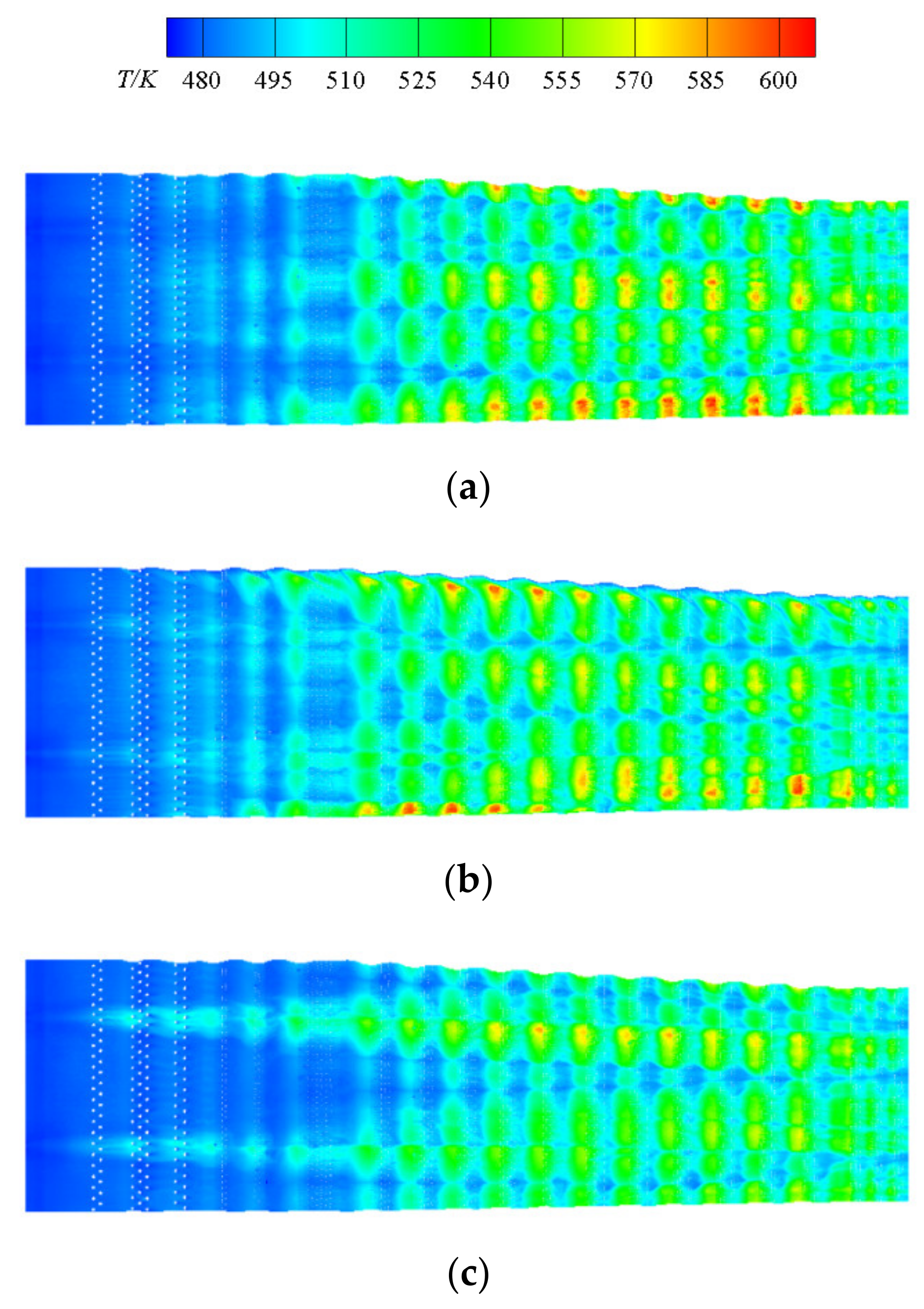
The wall temperature distribution of the heat shield under cases with different cooling flow structure parameters is shown in Figure 14. The overall temperature of the heat shield was comparatively low, which was caused by the fact that the afterburner was in a high bypass ratio and non-afterburning condition in this paper. This could also provide a reference for the influence of the cooling flow path structure parameters in the afterburning condition. The temperature of the front one-third area of the heat shield was relatively low under the combined action of the bypass flow from the heat shield inlet and afterburner annulus. As it came to the middle and rear regions, most of the bypass flow from the afterburner annulus was mixed with core flow. At this stage, the heat shield was mainly protected by the film cooling formed on its surface.
By comparing Figure 14a and Figure 14b, it could be concluded that the cooling effect on the heat shield did not improve significantly as the heat shield inlet height r. The reason for this could be that the cooling flow rate into the heat shield was relatively high under the conditions mentioned above, resulting in it not being the crucial factor for the cooling effect. Moreover, as mentioned in Section 3.2 of this paper, the non-uniformity of the heat shield inlet velocity also did not improve significantly when its height r increased. The phenomenon noted was that the velocity could be too fast in all regions except those for which the long and short flameholders are corresponding, which meant the cold flow at the middle and rear regions could not be attached to the heat shield after flowing through the gas film hole. Therefore, the strip-shaped local high-temperature zones would emerge at the middle and rear zones of the heat shield.
By comparing Figure 14a and Figure 14c, it can be found that the wall temperature distribution of the heat shield changed significantly with the increase of afterburner annulus inlet e. As for the front region of the heat shield, the zone corresponding to the long and short radial flameholder was clearly distinguished from the others due to the increase in the flow rate of the bypass flow through the afterburner annulus at this time. For the middle and rear regions of the heat shield, the flow in the heat shield slowed down, and the inlet velocity distribution could be more uniform so that effective air film cooling could be formed on its surface. Therefore, the overall distribution of its wall temperature was more even, and the average cooling efficiency increased by nearly 0.8%.

4. Conclusions

Numerical methods can be adopted to recognize the flow characteristics of integrated afterburner meticulously. In this paper, the effects on the flow and mixing characteristics and cooling performance of each component of integrated afterburner were analyzed by varying the cooling flow path structure parameters to change bypass flow distribution. The main conclusions can be drawn as follows:
(1)
In the range of parameters studied in this paper, most of the bypass flow flows into the heat shield channel or afterburner, while only a small part enters flameholders for cooling. The inlet velocity of the heat shield is not significantly affected by the heat shield inlet height r, but it becomes more uniform with the increase of the afterburner annulus height e.
(2)
The total pressure recovery coefficient varies at the trailing edge of the shunt ring and downstream of the flameholder with the increase of heat shield inlet height r and afterburner annulus height e, and its increasing rate at the outlet of the afterburner is 1.12% and 1.19%, respectively. Thermal mixing efficiency decreases by 5.4% at the outlet of the afterburner with the increase of heat shield inlet height r, and the increasing rate of it is about 2.9% for the afterburner annulus height e.
(3)
As the heat shield inlet height r and afterburner annulus height e increase, the average cooling efficiency of radial flameholder, circumferential flameholder, and fuel injector all have a tendency to decrease, and the decreasing rate is related to their locations, which determining the extent influenced by the bypass flow distribution. The cooling efficiency of the heat shield increases slightly caused by the uniformity of its inlet velocity and the action of its internal cooling flows.

Author Contributions

Conceptualization, X.J. and Y.S.; Data curation, X.J.; Formal analysis, X.J. and Y.S.; Funding acquisition, Y.S., X.X. and X.T.; Investigation, X.J. and Y.S.; Methodology, X.T. and J.Z. All authors have read and agreed to the published version of the manuscript.

Funding

This research was funded by National Science and Technology Major Project (Grant No. J2019-III-0019-0063).

Conflicts of Interest

The authors declare no conflict of interest.

Nomenclature

P af * Total pressure of airflow at afterburner inlet (Pa)
P by * Total pressure of airflow at bypass inlet (Pa)
P r * Total pressure of airflow in the reference section (Pa)
TafTemperature of airflow at afterburner inlet (K)
TbyTemperature of airflow at bypass inlet (K)
TmixTemperature of airflow after complete mixing (K)
TwAverage temperature of the components (K)
rRadial height of heat shield inlet (mm)
eRadial height of afterburner annulus (mm)
m . af Mass flow rate of airflow at afterburner inlet (kg/s)
m . by Mass flow rate of airflow at bypass inlet (kg/s)
v x * Characteristic velocity coefficient
σ Total pressure recovery coefficient
η t Thermal mixing efficiency
η ¯ Average cooling efficiency of components

References

  1. Koutmos, P.; McGuirk, J.J. Turbofan forced mixer/nozzle temperature and flow field modelling. Int. J. Heat Mass Transf. 1989, 32, 1141–1153. [Google Scholar] [CrossRef]
  2. Lefebvre, A.H.; Ballal, D.R. Gas Turbine Combustion: Alternative Fuels and Emissions. CRC Press: Boca Raton, FL, USA, 2010. [Google Scholar]
  3. Madabhushi, R.; Choi, D.; Barber, T. Unsteady simulations of turbulent flow behind a triangular bluff body. In Proceedings of the 33rd Joint Propulsion Conference and Exhibit, Seattle, WA, USA, 6–9 July 1997; p. 3182. [Google Scholar]
  4. Clements, T.R.; Graves, C.B. Augmentor burner. US5385015A, 31 January 1995. [Google Scholar]
  5. Lovett, J.; Brogan, T.; Philippona, D.; Kiel, B.; Thompson, T. Development needs for advanced afterburner designs. In Proceedings of the 40th AIAA/ASME/SAE/ASEE Joint Propulsion Conference and Exhibit, Fort Lauderdale, FL, USA, 11–14 July 2004; p. 4192. [Google Scholar]
  6. Raffoul, C.; Nejad, A.; Spring, S. Entrainment and mixing characteristics of bluff body flameholders-An experimental and numerical study. In Proceedings of the AIAA, 32nd Aerospace Sciences Meeting and Exhibit, Reno, NV, USA, 10–13 January 1994. [Google Scholar]
  7. Ebrahimi, H. Overview of gas turbine augmentor design, operation, and combustion oscillation. In Proceedings of the 42nd AIAA/ASME/SAE/ASEE Joint Propulsion Conference & Exhibit, Sacramento, CA, USA, 9–12 July 2006; p. 4916. [Google Scholar]
  8. Shahnam, M.; Wu, P.-K.; Kirkendall, K.; Nejad, A. Combustion instability of a diffusion flame using an integrated fuel injector/flameholder device. In Proceedings of the 36th AIAA Aerospace Sciences Meeting and Exhibit, Reno, NV, USA, 12–15 January 1998; p. 639. [Google Scholar]
  9. Zhang, D.; Song, W.J.A.A. Experimental study of cone-struts and cavity flameholders in a kerosene-fueled round scramjet combustor. Acta Astronaut. 2017, 139, 24–33. [Google Scholar] [CrossRef]
  10. Huang, Y.; He, X.; Jin, Y.; Zhu, H.; Zhu, Z.J.E. Effect of non-uniform inlet profile on the combustion performance of an afterburner with bluff body. Energy 2020, 216, 119142. [Google Scholar] [CrossRef]
  11. Safdar, M.M.; Masud, J.; Ullah, A. Numerical Analysis of Afterburner Characteristics of a Low Bypass Ratio Turbofan Engine at Various Flight Conditions. In Proceedings of the AIAA Scitech 2020 Forum, Orlando, FL, USA, 6–10 January 2020; p. 2248. [Google Scholar]
  12. Safdar, M.M.; Masud, J.; Mufti, B.; Naseer, H.U.; Farooq, A.; Ullah, A. Numerical Modeling and Analysis of Afterburner Combustion of a Low Bypass Ratio Turbofan Engine. In Proceedings of the AIAA Scitech 2020 Forum, Orlando, FL, USA, 6–10 January 2020; p. 0628. [Google Scholar]
  13. Li, F.; Bingbing, Z.; Xiong, L.; Liming, H.; Jun, D.; Jianping, L.; Zichen, Z.; Zhiyu, Z.J.P.S. Application study on plasma ignition in aeroengine strut–cavity–injector integrated afterburner. Technology 2021, 23, 105504. [Google Scholar]
  14. Agarwal, K.K.; Krishna, S.; Ravikrishna, R.V. Mixing Enhancement in a Compact Trapped Vortex Combustor. Combust. Sci. Technol. 2013, 185, 363–378. [Google Scholar] [CrossRef]
  15. Jiang, B.; Jin, Y.; Liu, D.; Wu, Z.; Ding, G.; Zhu, Z.; He, X.J.E.T.; Science, F. Effects of multi-orifice configurations of the quench plate on mixing characteristics of the quench zone in an RQL-TVC model. Exp. Therm. Fluid Sci. 2017, 83, 57–68. [Google Scholar] [CrossRef]
  16. Zhang, R.; Fan, W.; Shi, Q.; Tan, W.J.A.S. Structural design and performance experiment of a single vortex combustor with single-cavity and air blast atomisers. Aerosp. Sci. Technol. 2014, 39, 95–108. [Google Scholar] [CrossRef]
  17. Hsu, K.-Y.; Goss, L.P.; Roquemore, W.M. Characteristics of a Trapped-Vortex Combustor. J. Propuls. Power 1998, 14, 57–65. [Google Scholar] [CrossRef]
  18. Zhang, R.; Bai, N.; Fan, W.; Yan, W.; Hao, F.; Yin, C.J.E. Flow field and combustion characteristics of integrated combustion mode using cavity with low flow resistance for gas turbine engines. Energy 2018, 165, 979–996. [Google Scholar] [CrossRef]
  19. Li, M.; He, X.; Zhao, Y.; Jin, Y.; Ge, Z.; Sun, Y.J.A.E. Dome structure effects on combustion performance of a trapped vortex combustor. Appl. Energy 2017, 208, 72–82. [Google Scholar] [CrossRef]
  20. Abreau, M. Gas-Cooled Flameholder Assembly. U.S. Patent 5,076,062, 31 December 1991. [Google Scholar]
  21. Woltmann, I.E.; Mayer, J.C.; Manteiga, J.A. Gas Turbine Engine Ignition Flameholder with Internal Impingement Cooling. U.S. Patent 5,396,761, 14 March 1995. [Google Scholar]
  22. Lubarsky, E.; Cross, C.; Cutright, J.; Zinn, B.; Knaus, D.; Magari, P. Novel carbureted flameholder for improved afterburner stability. In Proceedings of the 46th AIAA Aerospace Sciences Meeting and Exhibit, Reno, NV, USA, 7–10 January 2008; p. 98. [Google Scholar]
  23. Chan, T.; Haiping, C. Numerical Simulation of Effusion Holes on the Longitudinal Ripple Heat Shield. J. Aerosp. Power 2009, 1. [Google Scholar]
  24. Qu, L.; Zhang, J.; Tan, X.; Wang, M. Numerical investigation on adiabatic film cooling effectiveness and heat transfer coefficient for effusion cooling over a transverse corrugated surface. Chin. J. Aeronaut. 2017, 30, 677–684. [Google Scholar] [CrossRef]
  25. Scrittore, J.J.; Thole, K.; Burd, S.W. Investigation of Velocity Profiles for Effusion Cooling of a Combustor Liner. J. Turbomach. 2006, 129, 518–526. [Google Scholar] [CrossRef]
  26. Singh, K.; Premachandran, B.; Ravi, M.J.A.T.E. Experimental and numerical studies on film cooling of a corrugated surface. Appl. Therm. Eng. 2016, 108, 312–329. [Google Scholar] [CrossRef]
  27. Ravichandran, M.; Ganesan, V.J.E.i.f. Aerodynamic flow investigations in an isothermal model of an afterburner. Exp. Fluids 1994, 17, 59–67. [Google Scholar] [CrossRef]
  28. Qiu, H.; Zhang, J.; Sun, X.; Chang, J.; Bao, W.; Zhang, S. Flowing residence characteristics in a dual-mode scramjet combustor equipped with strut flame holder. Aerosp. Sci. Technol. 2020, 99, 105718. [Google Scholar] [CrossRef]
  29. Miao, J.; Fan, Y.; Wu, W.; Zhao, S. Influence of air-entraining intensity on the afterburner ignition, flame-holding and combustion characteristics. Aerosp. Sci. Technol. 2020, 106, 106063. [Google Scholar] [CrossRef]
  30. Huang, W.; Pourkashanian, M.; Ma, L.; Ingham, D.B.; Luo, S.-B.; Wang, Z.-G. Effect of geometric parameters on the drag of the cavity flameholder based on the variance analysis method. Aerosp. Sci. Technol. 2012, 21, 24–30. [Google Scholar] [CrossRef]
  31. Xie, Y.; Liu, Y.-H. A Modified Thermal Mixing Efficiency and its Application to Lobed Mixer Nozzle for Aero-Engines. Heat Transf. Res. 2011, 42, 317–335. [Google Scholar] [CrossRef]
Figure 1. Schematic diagram of integrated afterburner.
Energies 14 05842 g001
Figure 2. 2-D structure schematic of the integrated afterburner and layout of the cross-section: (a) 2-D structure schematic; (b) partially enlarged view of radial flameholder.
Energies 14 05842 g002
Figure 3. Schematic diagram of computational domain structure.
Energies 14 05842 g003
Figure 4. Schematic diagram of feature faces: (a) heat shield inlet and afterburner annulus; (b) outlet of radial and circumferential flameholder.
Energies 14 05842 g004
Figure 5. Comparison of axial velocity distribution between experimental result and CFD result.
Energies 14 05842 g005
Figure 6. Surface mesh on various components of afterburner: (a) computational domain; (b) detailed view of flameholder and shunt ring.
Energies 14 05842 g006
Figure 7. Non-dimensionalized average temperature of heat shield for baseline model.
Energies 14 05842 g007
Figure 8. Distribution of bypass flow under cases with different cooling flow path structure parameters: (a) heat shield inlet height r; (b) afterburner annulus height e.
Energies 14 05842 g008
Figure 9. Streamline and velocity distribution on the symmetry plane: (a) baseline model; (b) r4e1; (c) r1e4.
Energies 14 05842 g009
Figure 10. Schematic diagram of dividing heat shield inlet.
Energies 14 05842 g010
Figure 11. Distribution of inlet velocity coefficient of heat shield under cases with different cooling flow path structure parameters: (a) heat shield inlet height r; (b) afterburner annulus height e.
Energies 14 05842 g011
Figure 12. Total pressure recovery coefficient along the flow path under cases with different cooling flow path structure parameters: (a) heat shield inlet height r; (b) afterburner annulus height e.
Energies 14 05842 g012
Figure 13. Thermal mixing efficiency along the flow path under cases with different cooling flow path structure parameters: (a) heat shield inlet height r; (b) afterburner annulus height e.
Energies 14 05842 g013
Figure 14. Temperature distribution of heat shield under cases with different cooling flow path structure parameters: (a) baseline model; (b) r4e1; (c) r1e4.
Energies 14 05842 g014
Table 1. Value of models with different cooling flow path structure parameters.
Modelr/mme/mm
r1e112.58.5
r2e113.58.5
r3e115.58.5
r4e117.58.5
r1e212.59.5
r1e312.511.5
r1e412.513.5
Table 2. Boundary conditions.
ParameterAfterburner InletBypass Inlet
Mass flow rate(kg/s)10.36.0
Total pressure(MPa)0.420.48
Total temperature(K)1130470
Table 3. Major losses of the flow in integrated afterburner and the reasons.
SectionMajor LossesReasons
1–3Diffusion lossthe diffusive process of core flow
Local lossthe sudden expansion or contraction of flow path
Friction lossthe flow through the wall
3–5Mixing lossthe mixing of core flow and bypass flow
5–7Friction lossthe flow through the contraction channel
Table 4. Average cooling efficiency of components under cases with different cooling flow path structure parameters.
ModelRadial
Flameholder
Circumferential
Flameholder
Fuel InjectorHeat Shield
r1e10.3960.5120.8730.946
r2e10.3910.5090.8700.951
r3e10.3850.4990.8600.942
r4e10.3800.4900.8520.946
r1e20.3910.5100.8700.954
r1e30.3860.5000.8670.952
r1e40.3790.4900.8610.954
Publisher’s Note: MDPI stays neutral with regard to jurisdictional claims in published maps and institutional affiliations.