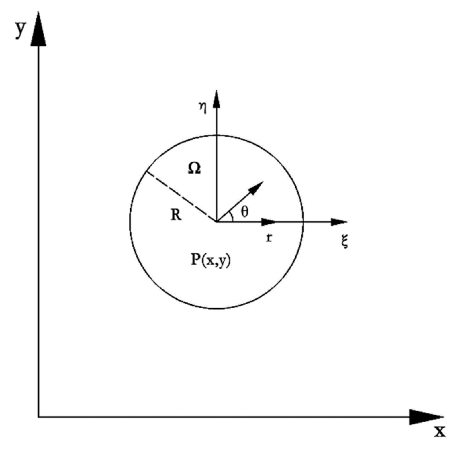
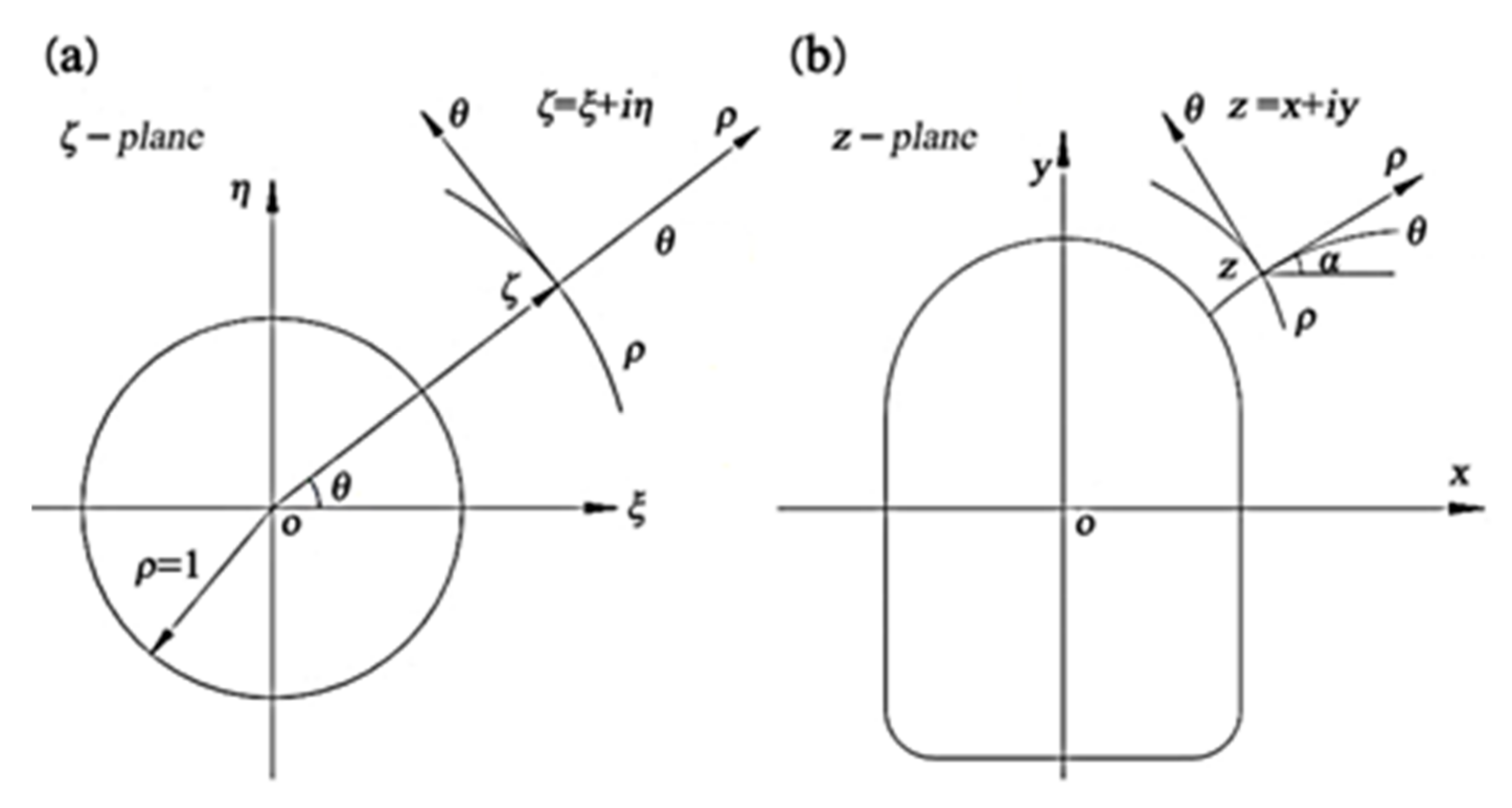
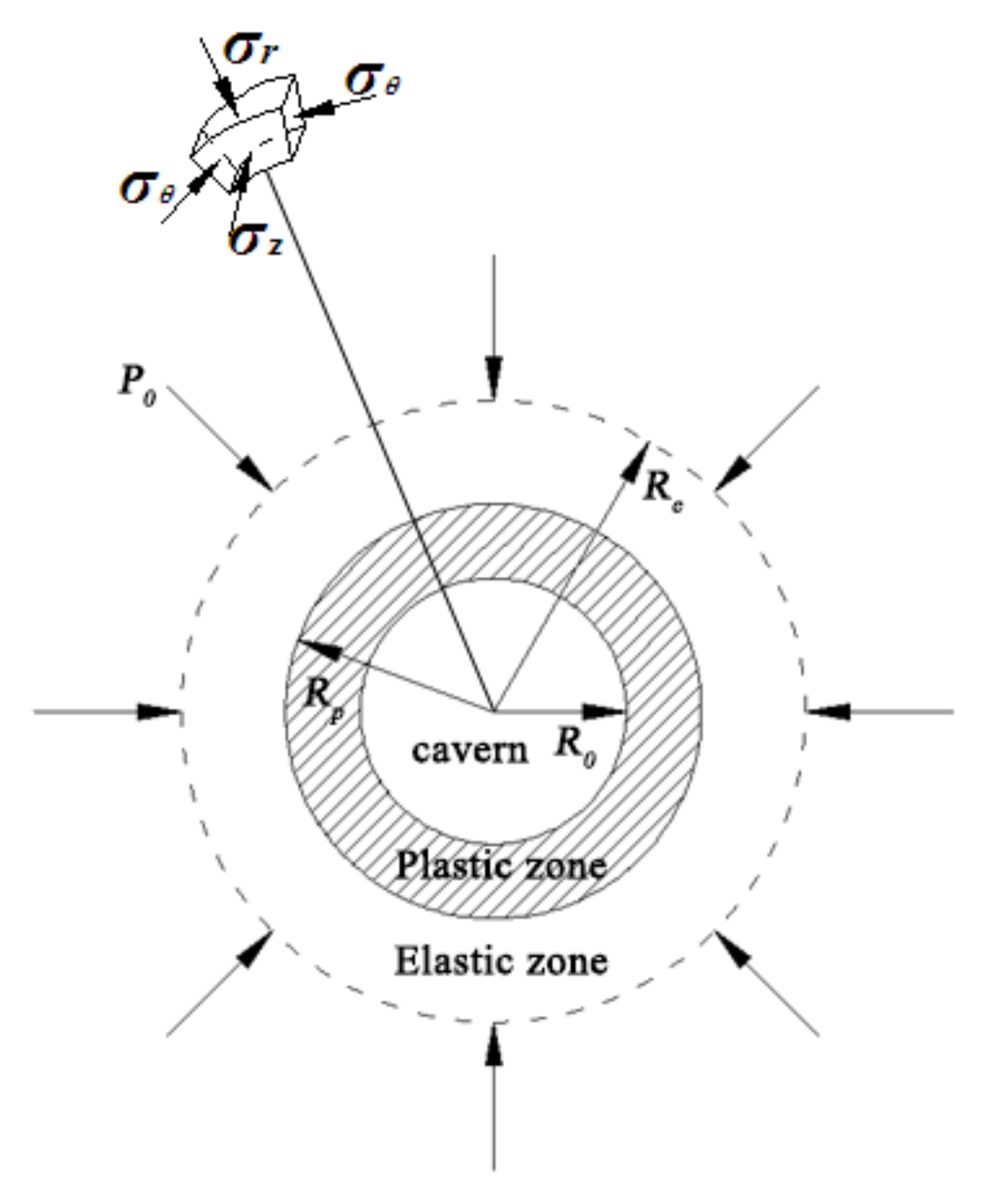
5.3. Derivation of Related Equations for Surrounding Rock of Deep Circular Cavern
The damage is not considered when the surrounding rock is in an elastic state. Combining the previous constitutive equations (Equations (34) and (35)) and the equilibrium equation (Equation (52)) together, the equilibrium equation for the elastic stage of the surrounding rock of the cavern can be obtained:
In order to solve the above-mentioned fourth-order ordinary differential equation and transform the higher-order ordinary differential equilibrium equation into a system of first-order differential equations, the following auxiliary variables need to be defined first:
The following expression can be obtained:
The corresponding coefficients in the above formula are:
,
,
,
. The boundary conditions at the boundary of the elastic zone (
) can also be obtained:
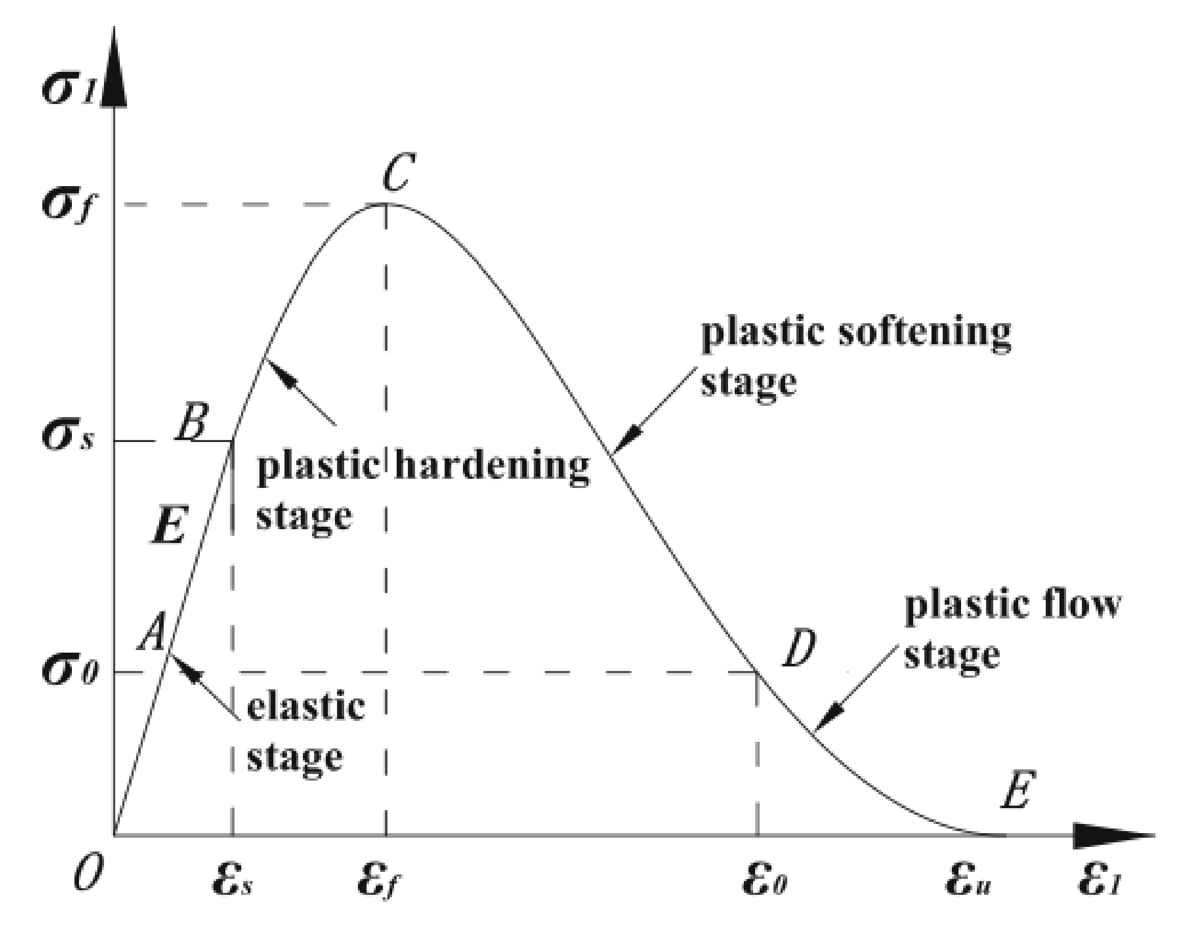
From the previously assumed yield function (Equation (16)), using the method of calculating the stress and displacement of the surrounding rock plastic zone used [
49], we can obtain:
Then, the equation of the plastic damage state of the surrounding rock of the cavern can be obtained:
Substituting the previous static balance equation (Equation (36)) can obtain:
Define the same auxiliary variable as the elastic segment (Equation (56)), but the expression should be written as follows:
The corresponding coefficients in the above formula are:
,
,
,
,
,
,
,
,
,
,
. The expressions of
A,
B and
E are as follows:
The boundary conditions at the inner boundary (
) of the post peak strain softening zone can be obtained:
5.4. Solution Method for Displacement and Stress
The equilibrium equation (Equation (55)) in the elastic state and the equilibrium equation (Equation (61)) in the plastic damage state are both fourth-order ordinary differential equations (ODE), and the corresponding boundary conditions (Equation (57)) and (Equation (64)) are third-order ordinary differential equations. It is almost impossible to obtain analytical solutions to the above problems. Therefore, the numerical solutions of the above problems are solved by using MATLAB numerical analysis software.
The boundary conditions given in the above problems belong to boundary value problems at the inner and outer boundaries of surrounding rock; when the ODE45 function is used in MATLAB numerical analysis software, it should be first transformed into initial value problems. ODE45 is a special function for solving differential equations in MATLAB numerical analysis software, which adopts the fourth-fifth order Runge–Kutta algorithm. Its fourth-order algorithm provides candidate solutions, and the fifth-order algorithm controls errors. It is an adaptive step size numerical solution of ordinary differential equations and solves Nonstiff ordinary differential equations.
When applying the ODE45 function to solve high-order ordinary differential equations, it is necessary to provide initial solutions for calculation intervals and differential equations, and it is also necessary to convert high-order differential equations into first-order differential equations. The first-order differential equations transformed by higher-order differential equations have been given in the previous section. In order to solve the differential equation, it is still necessary to give the initial solution of the differential equation on the boundary. In the above problem, the surrounding rock in the range of A is in an elastic state. It is required to solve the fourth-order ordinary differential equation in the elastic zone (Equation (55)), and the initial solution on the outer boundary (Equation (58)) must be given, that is, the derivative values of each order of displacement at (, , and ).
From the calculation and analysis of Zhao et al. (2007), it can be seen that the displacement value obtained by applying two different theories (classical theory and strain gradient theory) in the elastic stage is not much different from its first derivative value. Therefore, the displacement value (
) and the displacement first derivative value (
) at E can be roughly estimated from the analytical solution of the thick-walled cylinder in the classical elastic theory, and then
and
are substituted into the boundary conditions (Equation (58)) to obtain
and
. In this way, the initial solution on the boundary required to solve the higher-order differential equation is obtained. The analytical solution of the thick-walled cylinder in the classical elastic theory is as follows:
In the above equation, E and are the elastic modulus and Poisson’s ratio of the surrounding rock respectively, a and b are the inner and outer diameters of the cylinder respectively, and and are the pressures on the inner and outer walls of the cylinder, respectively.
Due to the continuity of the deformation of the surrounding rock of the cavern,
is both the inner boundary of the elastic zone and the outer boundary of the plastic damage zone, that is to say, the surrounding rock conforms to the equilibrium equation of the elastic zone (Equation (39)) and plastic damage zone (Equation (45)). Therefore, the following method is used to determine the size of
: first, the calculation interval is set as
; combined with the initial values of the displacement derivatives
,
,
and
on the outer boundary of the elastic zone are estimated and determined; the ODE45 function in MATLAB is used to solve the differential equations (Equation (57)), and the numerical solution of each point in the range of
can be obtained. According to the research of Gao et al. [
8], find a point that satisfies the Equation (66), and the distance between this point and the center of the roadway is the size of
.
After the boundary between the elastic zone and plastic damage zone is determined, the displacement derivatives (, , and ) on the inner boundary of the elastic zone can be calculated; it is taken as the initial value on the outer boundary of the plastic damage zone, and the calculation interval is set as ; the numerical solution (, , and ) of each point in the range of can be obtained by solving the differential equations (Equation (62)) with ODE45 function in MATLAB.
Take the derivative values of the displacements (
,
,
and
) on the boundary of the plastic damage zone and substitute them into Equations (67) and (68) to check the calculation errors. This calculation error is caused by the estimated initial value (
,
,
and
) on the outer boundary of the elastic zone. If the error meets the requirements (
), the calculation ends to obtain the numerical solution of the entire calculation area; if the error does not meet the requirements (
), adjust the initial value on the outer boundary of the elastic zone and repeat the above calculation steps until the error meets the requirements, and obtain the numerical solution of the entire calculation area. The calculation flowchart of the solution process is shown in
Figure 7.
5.5. Analysis of Theoretical Calculation Results
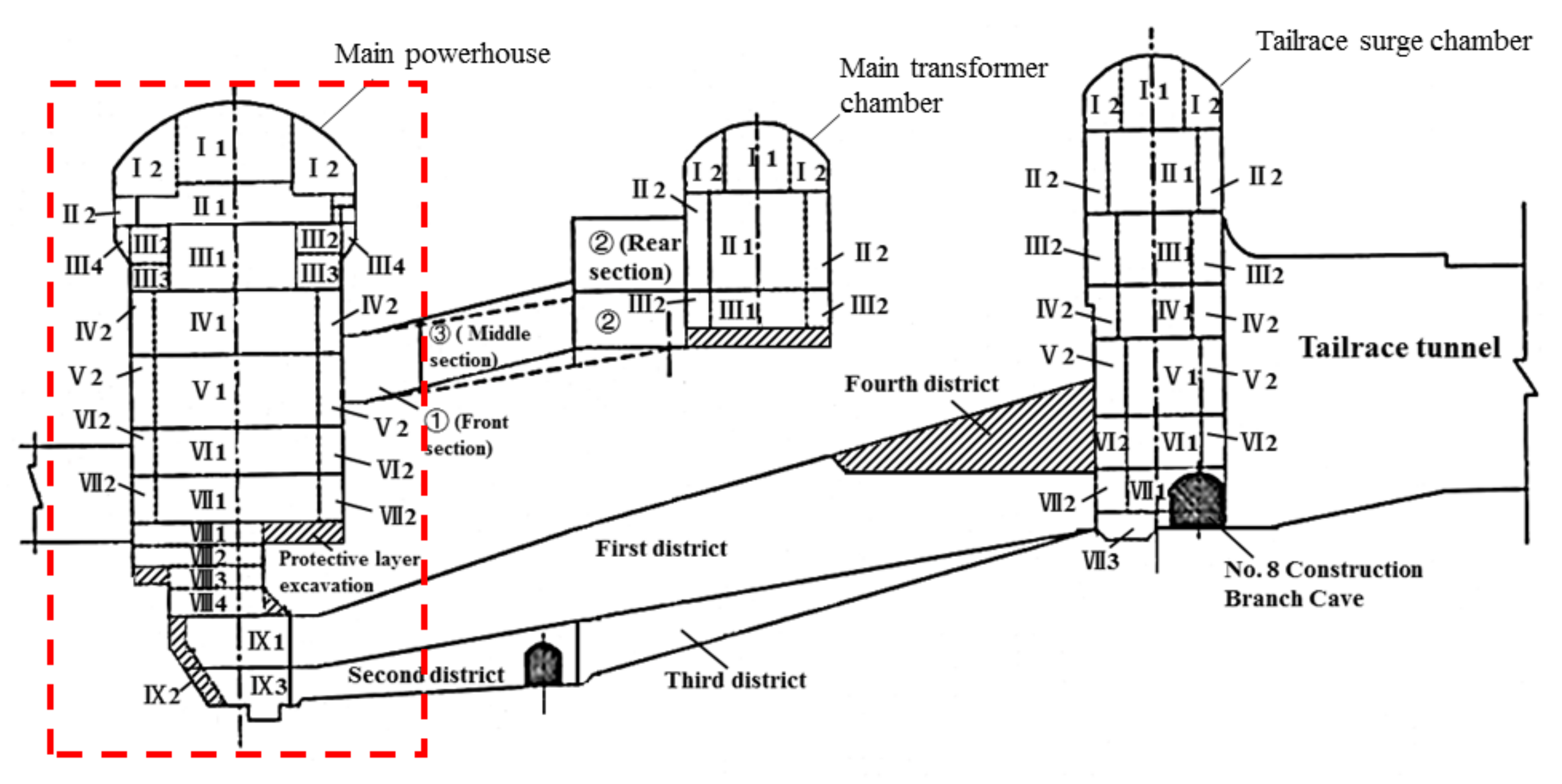
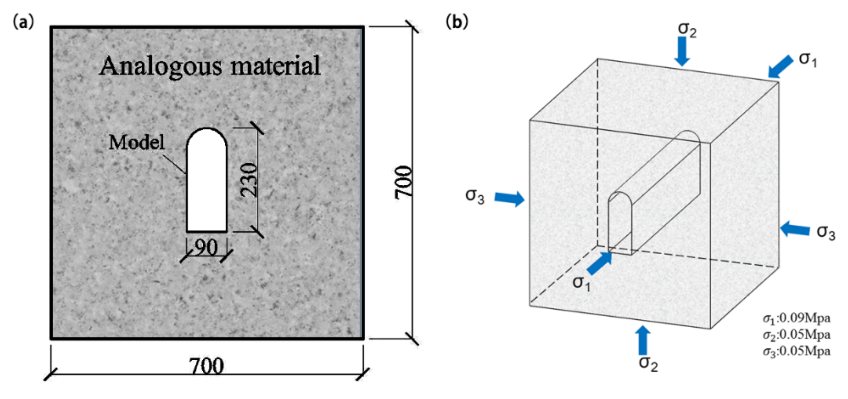
In this paper, the radial displacement, radial stress, and tangential stress distribution of the high sidewall cavern are obtained using rock parameters (
Table 2) of the Pubugou Hydropower Station as calculation parameters. The top of the main powerhouse is 360 m from the ground surface and the cross-section size of the cavern cross-section is measures 26.8 m × 70.1 m. Then, the theoretical calculation results are compared and analyzed with the geomechanical model test results [
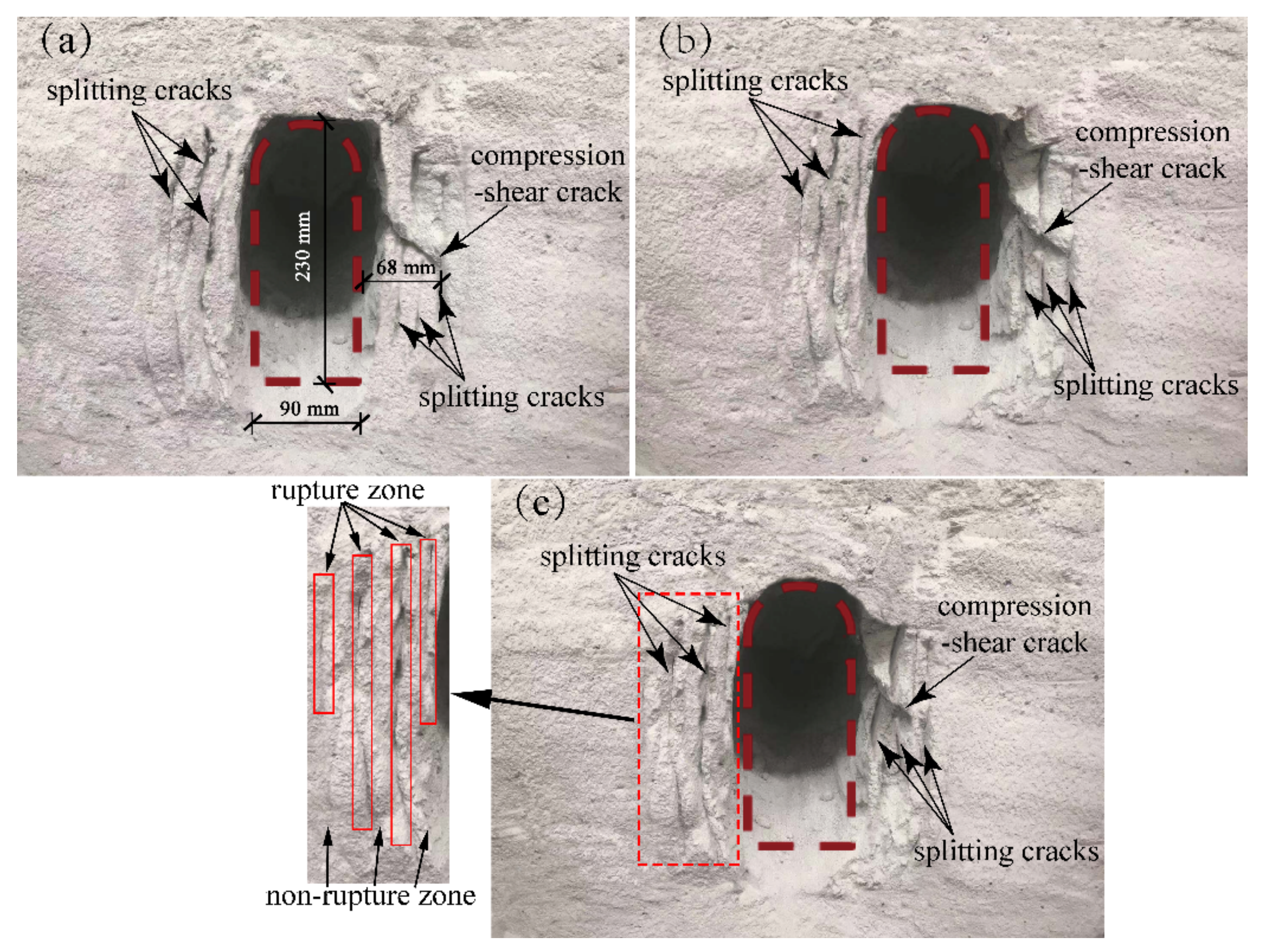
50] to initially verify the applicability of the splitting failure elastic-plastic damage model in the study of splitting damage in a deep cavern. The geomechanical model test program and results are shown in
Figure 8 and
Figure 9, respectively.
Using the above calculation parameters, the numerical solution of the radial displacement, radial stress, and tangential stress of the rock of the high sidewall cavern is calculated according to the solution process shown in
Figure 7. In this section, in order to facilitate the comparison between theoretical calculation results and model test results, all model test results are converted into prototypes based on the principles of similitude.
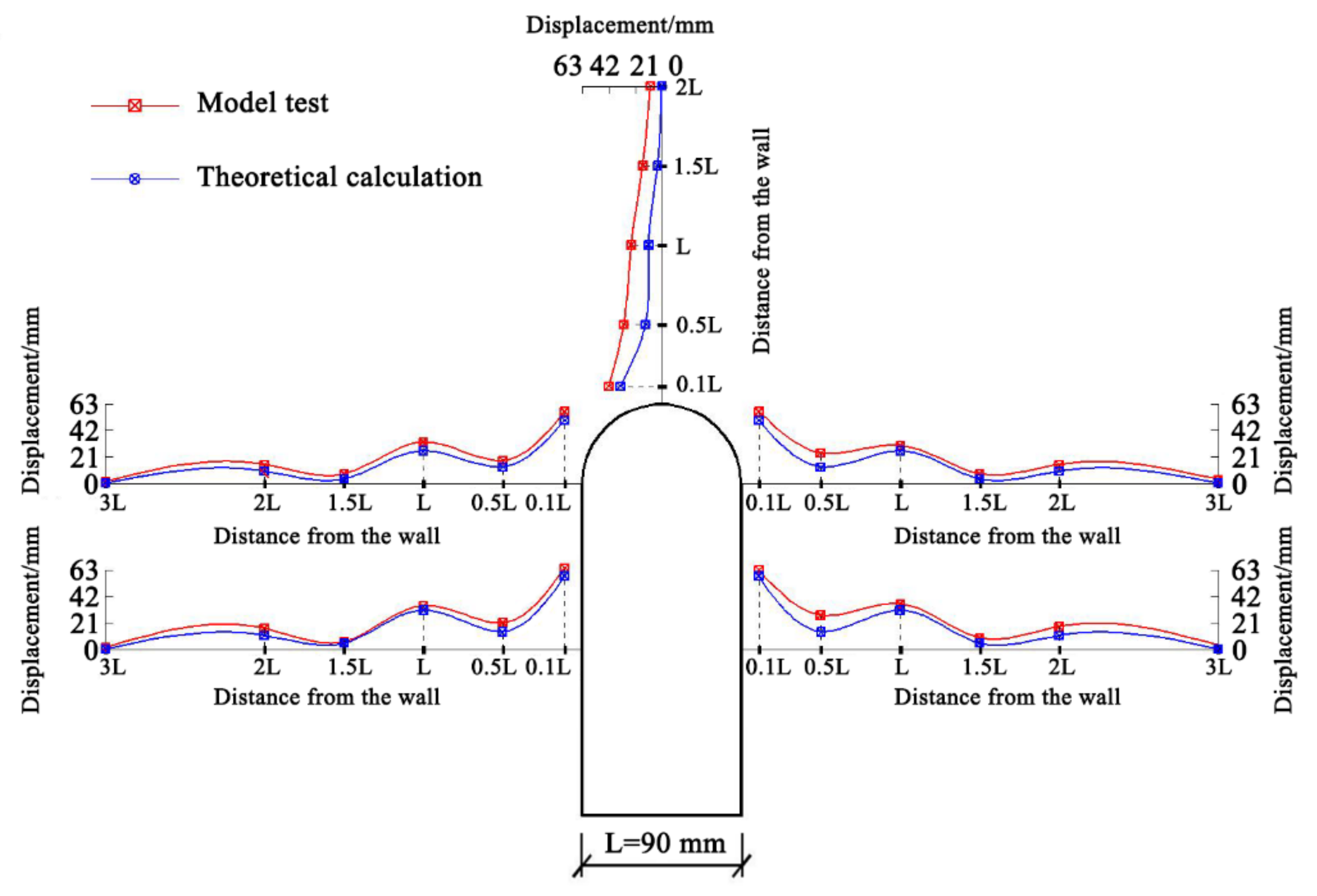
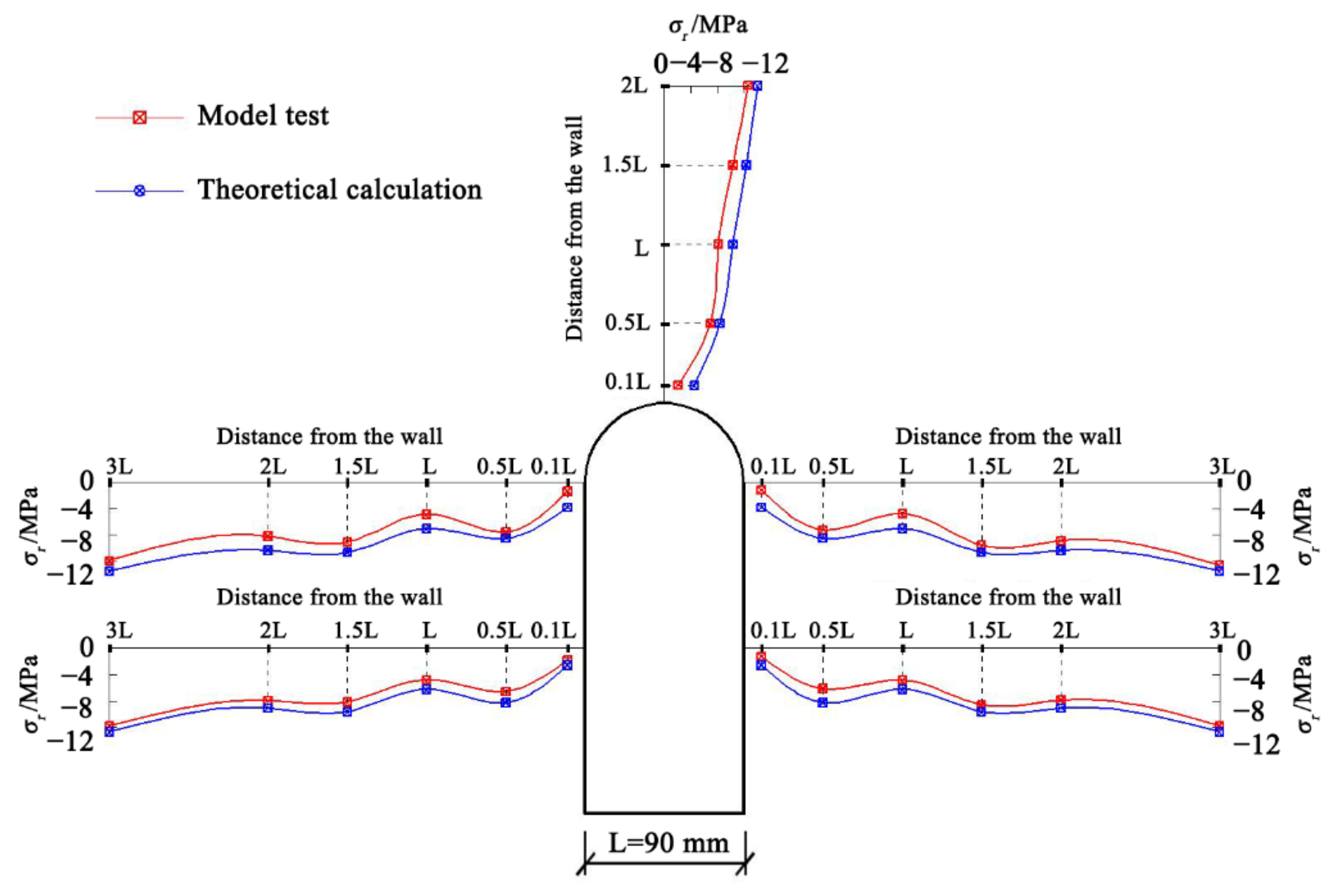
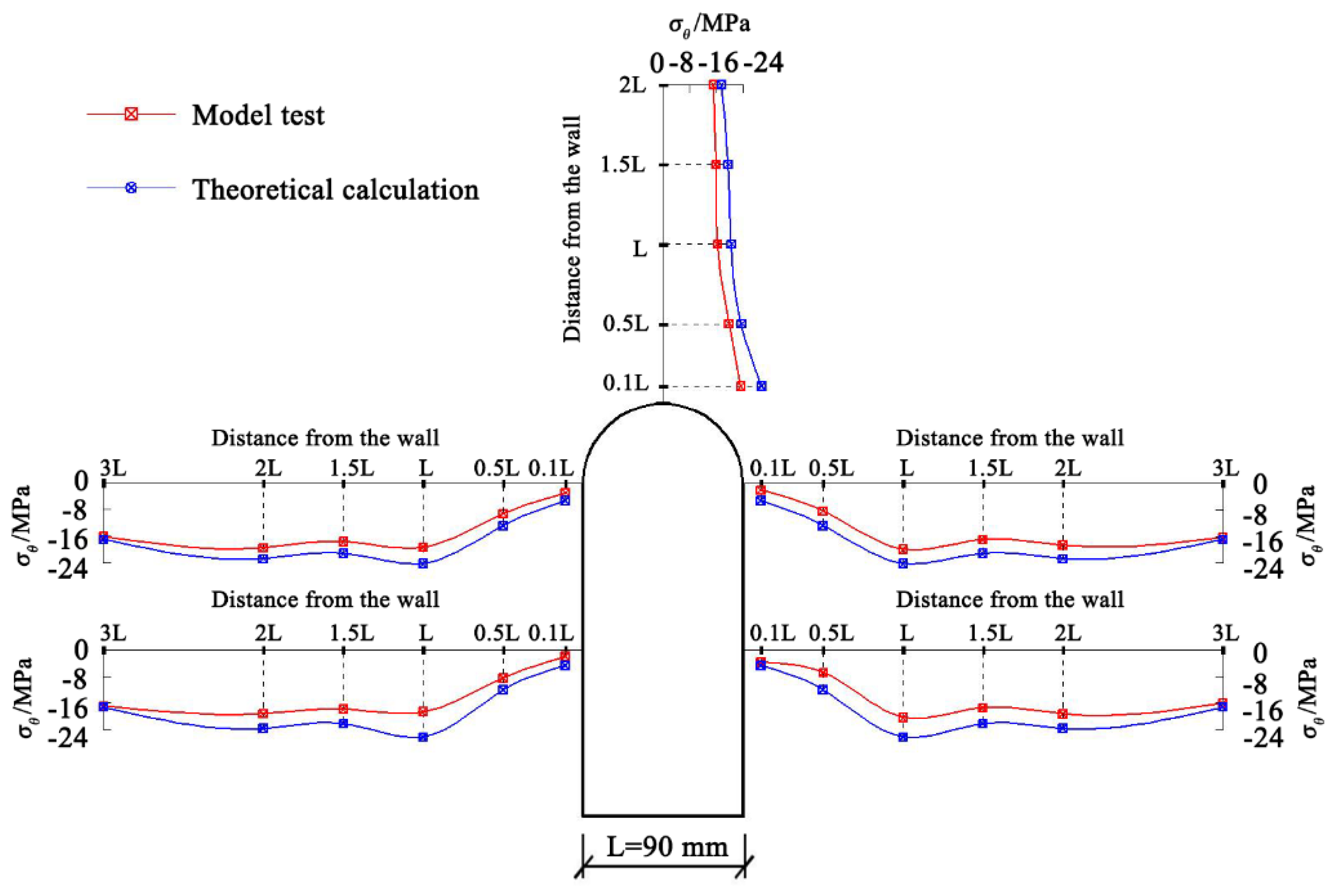
Figure 10 shows the radial displacement distribution diagram of the surrounding rock of the high sidewall cavern. The theoretically calculated values and experimentally measured values of the radial displacement, radial stress, and tangential stress at the corresponding positions of the measuring points around the cavern are listed in
Table 3.
It can be seen from
Figure 10 that the radial displacement at the high sidewall of the cavern obtained by using the elastic-plastic damage model of splitting failure shows an oscillating attenuation, and the oscillation amplitude gradually decreases with an increase in the distance from the sidewall, which is consistent with the variation measured by the model test. Because the theoretical model ignores the influence of excavation damage, the calculated displacement value is less than the displacement value of the model test. The difference close to the sidewall is as small as no more than 13%, and the value at the trough of the oscillating change is quite different, with the maximum difference being 12.66 mm. Comparing the measured values in
Table 3 with the calculated values, it can be seen that they are very close in most positions. It is preliminarily confirmed that the elasto-plastic damage model of splitting failure is applicable to the study of splitting failure of high sidewall cavern.
The stress distribution of rock of the high sidewall cavern was also obtained by using the splitting failure elastoplastic damage model, as shown in
Figure 11 and
Figure 12.
Table 4 and
Table 5 present the radial and tangential stresses of theoretical calculations and model tests, respectively.
Figure 11 shows the comparison of the radial stress distribution between theoretical calculation and model test. We find that the distribution of radial stresses is similar to that of displacements. The calculated radial stress value is relatively close to the test monitoring result, and the maximum difference does not exceed 2 MPa. As shown in
Figure 12, the theoretically calculated tangential stress distribution is also consistent with the model test. When the distance from the sidewall is less than
L, the rock is in a plastic state and the tangential stress is released; when the distance from the sidewall is greater than
L, the tangential stress is concentrated and the rock is in an elastic state. The tangential stresses at the vault are all greater than the in-suit value (
σθ = 15.25 MPa). Due to ignoring the excavation disturbance, the calculated value of the tangential stress is generally greater than the test value. When the tangential stress just appears to be concentrated, the gap is large, and the maximum gap between the two is 28.83%.
The numerical solution of the radial displacement and radial stress of the surrounding rock of the high side wall cavern using the splitting failure elastoplastic damage softening model for theoretical calculations shows that the oscillation attenuation occurs alternately with wave crests and wave troughs. This is completely different from the monotonic attenuation obtained by using the classic continuous elastoplastic model and is consistent with the change rule obtained by the geomechanical model test. This indicates that the split failure elastoplastic damage model can explain the split failure of high side wall caverns under high ground stress conditions.
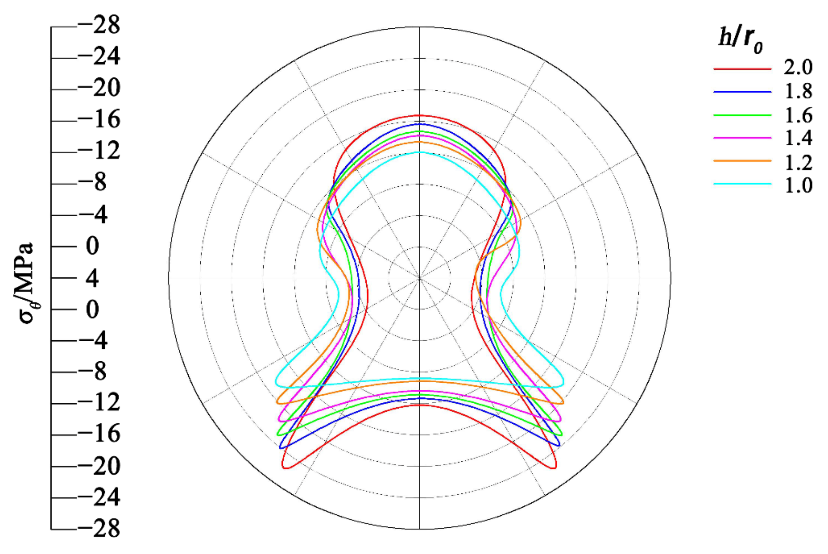
In order to study the formation mechanism of splitting failure of high sidewall caverns of hydropower stations, we compared the distribution of tangential stress around the high sidewall caverns under different height–span ratios, as shown in
Figure 13. We find that the stress distribution of the surrounding rock of the high side wall cavern is significantly affected by the height–span ratio. The tangential stress is unevenly distributed along the boundary of the cavern and is symmetrically distributed along the central axis of the cavern. There are obvious stress fluctuations in surrounding rock near the vault, arch toe, and lower corner of the side wall. With an increase in the height–span ratio of the cavern, the tangential stress of the vault and the lower corner becomes larger and larger. The maximum tangential stress at the midpoint of the side wall shows a decreasing trend. The release of the tangential stress increases gradually, and the damage of the surrounding rock increases gradually.


