1. Introduction
Concentrating Solar Power (CSP) technology can be considered as a mature technology for large-scale renewable energy production [
1,
2], destined to significantly contribute to the ambitious decarbonization objective set by the European Green Deal of greenhouse gas emissions reduction of at least 50% by 2030 and environmental neutrality by 2050. Moreover, this technology can play an important role in allowing high shares of solar PV and wind in the energy mix, thanks to its capability to provide dispatchable renewable heat/electricity. In the last decade, the cost of electricity from concentrating solar power has fallen by 68% and the installation costs of a CSP plants have been substantially halved [
3]. However, the CSP economic feasibility needs to be further addressed by improving the efficiency and durability of each plant component of concentrating solar plants, since it is generally agreed upon that higher components’ efficiency for longer times (at least 25 years) represents a crucial requirement for CSP economical sustainability [
4].
In Concentrated Solar Thermal (CST) technology, the solar field, constituted of multiple solar collectors, represents the distinctive, and the costliest, element. The collectors intercept the incoming radiation and concentrate it on the receiver surface, where a heat transfer fluid absorbs the concentrated radiation in the form of sensible heat. The sensible heat can then be stored and converted into electricity or supplied as thermal energy to endothermic processes. In linear focusing CST technology, two types of collectors are currently used: parabolic trough collector (PTC) and linear Fresnel collector (LFC) [
5,
6,
7,
8,
9,
10]. In these systems, mirrors concentrate the solar energy on tube receivers covered with a spectrally selective absorber coating characterized by high solar absorptance (α
s) and low thermal emittance (ε
th) at the operating temperature, in order to maximize the energy absorption and minimize the heat losses toward the ambient.
The solar absorber coating can be considered as a strategic element of solar receivers, since the efficiency, durability and economic feasibility of a solar plant strongly depend on its photo-thermal conversion efficiency and thermal stability. An ideal spectrally selective absorber coating should have zero reflectance in the visible region and unit reflectance in the infrared region. In order to obtain this shape of reflectance, an accurate design of the absorber coating is required. The use of metal–ceramic (cermet) composite coating is one of the most widely approach to obtain spectrally selective absorber coatings for medium and high temperature applications [
11,
12,
13,
14]. Among the deposition technologies of the cermet-based coatings, Magnetron sputtering has proved to be particularly suitable to fabricate absorber coatings with the target characteristics [
15,
16,
17,
18,
19,
20,
21,
22,
23,
24,
25]. This technology allows controlling the size and quantity of the metallic and ceramic particles inside the composite materials with high accuracy. Furthermore, this technology is particularly suitable to industrial production thanks to its capability to deposit on large area at a high rate and low cost [
26,
27].
Since 2005, ENEA has been developing and patenting solar absorber coatings suitable for medium (400 °C) and high (550 °C) temperature applications, based on the technology of double nitride cermet [
26,
28]. These coatings have infrared reflector of silver (Ag) or tungsten (W), depending on the applicative temperature, covered by a graded multilayer cermet of tungsten nitride and aluminum nitride (WN-AlN) and, lastly, by an antireflection filter (AR) of aluminum nitride (AlN) and silica (SiO
2) [
28]. The Ag infrared reflector allows maintaining the thermal emissivity of the absorber coating low, thanks to its high reflectance in the infrared region. However, the high diffusivity of Ag atoms undermines the structural and chemical stability of the coating, compromising its use at high temperatures for a long time. Differently, coatings with W as infrared reflector exploit the low diffusivity of this metal to ensure negligible degradation of the photo-thermal performance at high temperature for long time. However, as a drawback, the thermal emissivity of the absorber coating is higher, since the reflectance of W is lower than the Ag one in the infrared region. Hence, Ag has proven reliability for medium-temperature applications, and W for high-temperature ones [
26]. The ENEA technology for solar coating manufacturing was acquired by Archimede Solar Energy (ASE) Company to produce and commercialize two typologies of receiver tube depending on the application temperature: the first one is a receiver tube with an Ag infrared reflector suitable for application up to 400 °C; the second has W as an infrared reflector, developed for applications up to 550 °C. Both receiver tubes are currently installed on demonstrative/commercial parabolic trough plants (AKESAI plant in China, DUBA 1 plant in Saudi Arabia, MATS plant in Egypt [
29]).
In the last 20 years, the research on CSP was partly focused on the increase of the plants’ operating temperatures in order to enhance the heat-to-electricity conversion efficiency and to reduce the electricity cost [
30,
31,
32,
33]. Many efforts have been made to develop selective absorbing coatings with good photo-thermal performance and long-term thermal stability at higher temperatures [
28,
34,
35,
36,
37,
38,
39,
40,
41,
42]. The aim of the present work is to increase the long-term thermal stability at a higher temperature of the previous ENEA solar absorber coating with Ag as infrared reflector, maintaining its excellent photo-thermal performance. For this purpose, a new coating, with an Ag infrared reflector and a graded multilayer cermet of W-AlN, was designed and manufactured by using high-energy and fast deposition processes. In detail, the growth of Ag infrared reflectors with improved thermal stability was promoted by implementing efficient surface pre-treatments of stainless steel (SS) substrate and placing the Ag layer between more compact and uniform layers of W and W-AlN than those of W and WN-AlN of the previous ENEA’s double-nitride cermet technology [
26,
28]. The coating was finally completed by depositing an additional antireflection filter based on AlN and SiO
2 ceramics in combination with a low Metallic Volume Fraction (MVF) cermet material.
An investigation method developed by ENEA [
43] was applied to estimate the long-term thermal stability of the new solar absorber coating and that of the coating based on the WN-AlN cermet [
28]. This method predicts the lifetime of the manufactured solar coatings by accelerated ageing tests conducted at temperatures above the operating one, with the aim of experimentally simulate the evolution of the coating over the years. Therefore, the coating was exposed to fast, but not unrealistic, degradation mechanisms. The temperatures of the accelerated tests were properly selected to activate the same degradation mechanisms that are associated to the real working conditions of the coating.
2. Materials and Methods
Metallic, ceramic and cermet films of the solar absorber coating were deposited by a sputtering technique by using a planar Magnetron sputtering system composed of a process chamber and a load lock chamber. In the load lock chamber, both plasma and heating pre-treatments can be performed on substrates. In the process chamber, six cathodes can be arranged in pairs on two opposite sides. Specifically, a Standard Magnetron cathode in DC (Direct Current) sputtering mode was employed for Ag deposition, whereas a Gencoa Unbalanced Magnetron cathode in DC sputtering mode was used to deposit the adaptive layer of W and the W metallic component of the multilayer cermet W-AlN. The first adaptive layer of W was grown on pre-treated SS substrate to improve adhesion as well as structural and chemical stability of the Ag layer [
44]. A high quality W film with a more compact structure and lower defects than previous ones was obtained by using in place of a standard Magnetron cathode [
28] the Unbalanced Magnetron cathode. This cathode is designed with a magnetic pole on the external perimeter strengthened with respect to the central pole. With this configuration, the unbalanced magnetic array changes the magnetic field shape, allowing the release of some plasma electrons towards the substrate, and thus, providing ion assistance during the coating deposition. On the deposited Ag layer, a W-AlN multilayer cermet was placed with the following purposes: to absorb solar radiation, stabilize the Ag infrared reflector and block the Ag diffusion in the neighboring layers. Additionally, in this case, a more compact and uniform multilayer cermet of W-AlN than that of WN-AlN of the previous ENEA’s double-nitride cermet technology was obtained by using the same Unbalanced Magnetron cathode as the one adopted for W deposition in place of a standard Magnetron [
28]. Two Dual Magnetron cathodes were used to deposit AlN and SiO
2 by MF (Medium Frequency) reactive sputtering technology in transition mode [
45]. In particular, the Dual Magnetron cathode for the AlN deposition was arranged on the opposite side of the Unbalanced Magnetron cathode in order to carry out the W-AlN cermet films in co-sputtering mode. The deposition plant is also equipped with a spectroscopic PEM system (PLASUS GmbH Company equipment, Mering, Germany) characterized by six independent spectrometer channels. The complete spectrum of the plasma light emission is acquired continuously by optical fibers in the wavelength range 200–1100 nm. Each Dual Magnetron cathode is monitored by two optical fibers, one fiber for each plasma region facing the two targets of the Dual Magnetron cathode. The control function of the PEM system is performed through a proportional-integral-derivative (PID) controller which allows maintaining unchanged target conditions during the reactive sputtering process. This control system makes possible the deposition of all ceramic components of the coating by means of reactive Magnetron sputtering technology in transition mode. A high deposition rate of the coating was guaranteed by using the DC sputtering technology to deposit all metallic components and the reactive Magnetron sputtering technology in transition mode with MF supply to grow all ceramic components [
46].
The Ag infrared reflector was deposited on SS planar substrates fixed inside housings on the external surface of a SS tube (L = 60 mm, D = 7 mm). This tube-holder moves back and forth with respect to the targets with an adjustable sweep velocity and rotates with a spin velocity that is also adjustable. The pre-treatment was performed through the heating of SS substrate by means of thermal radiation from three resistances warmed at a temperature of about 500 °C, followed by an ionic etching performed in argon (Ar) plasma at 2.0 Pa of pressure and by applying 3 kV DC voltage to the tube-holder. After pre-treatment, the tube-holder was transferred in the process chamber to deposit the adaptive layer of W. This layer was deposited with 13.33 W/cm2 power density applied to the cathode and at Ar pressure of 0.4 Pa. For this deposition, the spin velocity of the tube-holder was fixed at 15 rpm while the carrier sweep velocity was fixed at 50 cm/min. Hence, the Ag infrared reflector was grown with 4.39 W/cm2 power density applied to the cathode and at an Ar pressure of 1 Pa. The spin and sweep velocities were fixed at 30 rpm and 200 cm/min, respectively. The refractive index n and the extinction coefficient k of the Ag infrared reflector were estimated with the ellipsometric technique using a Variable Angle Spectroscopic Ellipsometer (VASE) equipment of J.A. Woollam Company (Lincoln, NE). This instrument enables to operate in the wavelength range 0.25–2.50 µm.
Four W-AlN cermet samples were deposited and optically characterized for the design of the graded multilayer cermet of the solar coating. To this aim, these samples were grown on glass planar substrates fixed using the same housing on the tube-holder. The cermet samples were grown in Ar + N
2 plasma, moving and rotating the tube-holder back and forth with respect to the Al and W targets. The sweep and spin velocities were fixed at 100 cm/min and 60 rpm, respectively. A total Ar flow equal to 400 sccm was injected in the process chamber from the gas-rings around the frontal Al and W targets (200 sccm for the side). The N
2 gas was introduced in the process chamber from the gas-ring around the Al targets and the flow was controlled by the PEM system. Process pressure was fixed at about 1 Pa. These four samples were deposited by applying a constant power density of 5.17 W/cm
2 to the Al targets, whereas the power densities applied to the W target are reported in
Table 1. Each sample in this table is classified as a function of the metallic volume fraction included in the cermet film.
A new AR filter was designed for the solar coating by using AlN and SiO2 ceramics in combination with a low MVF cermet material. Therefore, a fifth cermet sample, classified as Very Low MVF (VLMVF), was grown on glass planar substrates by using the same deposition parameters as the ones adopted for the other cermet samples, except for the power densities applied to the W target that was 0.89 W/cm2. This cermet was optically characterized and used to select the low MVF cermet material of the AR filter design. The AlN layer of the AR filter was grown on glass planar substrates in Ar + N2 plasma, moving and rotating the holder in front of the Al targets with sweep velocity of 100 cm/min and spin velocity of 60 rpm. A total Ar flow equal to 400 sccm was injected in the process chamber through the gas-rings around the frontal Al and W targets (200 sccm for the side) in order to maintain the same gas flow configuration as the one of the W-AlN cermet deposition. The N2 gas was introduced in the process chamber from the gas-ring around the Al targets and the flow was controlled by the PEM system. Process pressure was fixed at about 1 Pa, while the power density applied to the Al targets was 5.17 W/cm2. The SiO2 layer of the AR filter was grown on glass planar substrates in Ar + O2 plasma moving and rotating the holder in front of the silicon (Si) targets with the same sweep and spin velocities as the ones used to deposit the AlN film. A total Ar flow of 200 sccm was injected in the process chamber from the gas-ring around the Si targets. The O2 gas was introduced in the process chamber from the gas-ring around the Si targets and the flow was controlled by the PEM system. Process pressure was fixed at about 1 Pa, while the power density applied to the Si targets was 3.88 W/cm2.
The thickness of each ceramic and cermet samples was mechanically measured on films grown on glass substrate using a Tencor P-7 surface profiler.
Optical reflectance and transmittance measurements of ceramic and cermet samples were performed by a UV-Vis-NIR spectrophotometer, using a double-beam Perkin-Elmer mod. Lambda 950 instrument equipped with a 15 cm diameter integrating sphere. The refractive index n and the extinction coefficient k of each sample were estimated by an inversion method applied to the experimental reflectance and transmittance data [
47] and used to create a database. The database was completed with the Ag optical parameters and imported in Essential Macleod (Version 9.9.457/Manufacturer Thin Film Center Inc., Tucson, AZ, USA), a commercial software for the optical analysis of multilayer structures, to design the solar coating. Hence, the solar coating was fabricated and its optical reflectance was still measured by the Lambda 950 using the integrating sphere.
This spectrophotometer was also used to measure the high specular reflectance of the SS/W/Ag multilayer by a directional absolute reflectance “IV” accessory, designed to provide the highest possible accuracy for specular reflectance measurements of highly reflective materials. The optical reflectance of the SS/W/Ag multilayer was obtained by adding the specular reflectance to the diffuse reflectance measured by the same instrument with the integrating sphere.
Finally, the long-term thermal stability of the new solar absorber coating was estimated and compared with that of the coating based on the WN-AlN cermet [
28]. A procedure for accelerated life testing of absorber coatings was developed within the framework of the working group, ‘‘Materials in Solar Thermal Collectors’’ of the International Energy Agency—Solar Heating and Cooling Program [
48,
49,
50,
51,
52,
53]. The procedure was formulated as a standard and submitted to the International Organization for Standardization (ISO). The proposed standard has been applied to examine the long-term stability of absorber coatings used in flat-plate collectors for domestic hot water systems [
48,
49,
50,
51,
52,
53]. Unfortunately, a standard procedure has not been formalized yet to evaluate the long-term thermal stability of solar collectors for CSP plants. Moreover, the methodology for durability test procedures and the service lifetime prediction methods adopted by the leading manufacturers of receiver tubes have not been diffused and the scientific literature on the topic is lacking. Thus, in order to estimate the degradation of a solar absorber coating for CSP plants, ENEA has developed an investigation method that derives from the main guidelines of the standard procedure for assessing the thermal stability of hot water systems [
43]. Specifically, six samples (two samples for each test), having the same coating, were subjected to three accelerated ageing tests consistent of three separated treatments, by using a programmable oven able to operate up to 1000 °C at a pressure of 2 × 10
−2 Pa. The first test was carried out at 620 °C for a total duration of 1128 h, the second one at 650 °C for a total duration of 320 h and, finally, the last one at 690 °C for a total duration of 96 h. Solar absorptance and hemispherical emittance of the solar coating were calculated after every heat treatment by using the spectral reflectance measured by the Lambda 950 and by an infrared spectrometer at room temperature. The infrared reflectance was measured by a FTIR (Fourier Transform Infra-Red) spectrometer in the wavelength range 1.7–17 µm, by using a BRUKER mod. INVENIO X (Ettlingen, Germany) equipped with an MCT detector and a 7.5 cm diameter integrating sphere, coated with diffuse reflecting gold. The instrumental accuracy in the measurement of α
s and ε
th was equal to ±0.05% and ±0.14%, respectively.
3. Results and Discussion
The experimental work described in this article deals with the improvement of the structural and chemical stability at medium and high temperature of the solar coatings with Ag as infrared reflector previously developed by ENEA. To this purpose, efficient surface pre-treatments of SS substrates were implemented and an Ag layer was placed between layers of W and W-AlN, characterized by higher compactness and homogeneity than those of W and WN-AlN of the double-nitride cermet technology previously developed by ENEA [
26,
28]. An Unbalanced Magnetron cathode in place of a standard Magnetron was adopted to promote an ion-assisted deposition process that improved uniformity and compactness of the films above and below the Ag layer.
The multilayer structure of the optimized solar coating with improved thermal stability is composed of the following layers:
SS/W/Ag/graded cermet (W-AlN)/AR filter (AlN, low MVF cermet, SiO2).
In this section, the procedure developed to deposit each single layer useful for the design of the solar coating is described. Once the samples were manufactured, they were optically characterized and the refractive indexes and extinction coefficients were used to create a database to be employed for the design of the solar coating. The resulting design consisted of a sequence of layers with assigned thickness values and with a specific metal content profile of the graded multilayer cermet. Hence, the new coating was manufactured according to this design and optically characterized to evaluate αs and εth. Finally, the solar coating was subjected to accelerated ageing tests in order to estimate its structural and chemical stability.
3.1. Ag Infrared Reflector
The Ag infrared reflector was deposited on a SS substrate according to the operative conditions specified in the “Materials and Methods” section. In particular, a 120 nm thick layer of Ag was deposited on a 120 nm thick layer of W.
The optical characterization of the Ag layer was performed by the ellipsometric technique applied to the Ag layer deposited on SS/W structure. In this way, the optical estimation procedure was applied to the actual growth condition of the Ag layer during the solar coating fabrication. The spectral n and k values of the Ag layer deposited on SS/W structure were immediately determined by applying the equation of the pseudodielectric function [
54], which coincides with the actual dielectric function, with the metal thickness being sufficiently large to allow neglecting optical reflection at the W/Ag interface. In
Figure 1a, the optical parameters of the Ag layer are shown. These optical parameters were imported in Macleod to simulate the spectral reflectance of the Ag layer; this simulated curve was compared with the experimental spectral reflectance measured by spectrophotometric technique. In
Figure 1b, this comparison is reported. As can be seen, the good agreement between the simulated and experimental curve proves the accuracy of n and k estimation performed by the ellipsometric technique.
3.2. W-AlN Cermet
This section deals with the experimental activity carried out to develop the deposition process of cermet samples. Reactive sputtering technology in transition mode was employed in order to grow the AlN ceramic component of the cermet samples. This technology offers the possibility to grow ceramic materials at high deposition rate but with the drawback of major complexity of the deposition processes, with the target conditions being extremely sensitive to the quantity of reactive gas injected in the process chamber. Therefore, a PEM system is employed to verify the sputtering process conditions in the deposition chamber through the control and the management of emission spectral line intensity of any excited species involved in the plasma. To tune the PEM system, the intensity of the emission spectral line of the element selected as representative of the target conditions is acquired, increasing and then decreasing the reactive gas flow injected in the process chamber. The obtained curve, named the hysteresis curve, is used by the PEM system to manage the quantity of reactive gas introduced in the chamber in order to maintain unchanged the intensity of the emission spectral line of the controlled element during the deposition process.
Regarding the cermet deposition, the process developed by ENEA employs the same power density to grow the ceramic component and different power densities to deposit the metallic component. The N
2 gas was introduced in the process chamber from the gas-ring around the Al targets and controlled by the PEM system in order to maintain unchanged the Al emission spectral line during the process, with this line having high intensity and sensitivity to target condition variations. Since the hysteresis phenomenon can be mitigated by overpumping the process chamber [
45,
55,
56], a high Ar flow (400 sccm) was injected in the chamber during the cermet deposition. The resulting hysteresis curve was characterized by a slow variation of Al emission intensity from metallic to poisoned region as a function of the N
2 flow. In the ENEA process, all ceramic components of cermet samples are deposited with the same voltage at the Al targets; this reference voltage is selected by depositing the ceramic component alone and setting the Al emission intensity on the hysteresis curve so as to obtain the expected optical properties for the ceramic material [
46]. The hysteresis curve of Al emission intensity was acquired at a high Ar flow (400 sccm) and several values of intensity were selected along this curve to deposit AlN samples with different optical properties. Each deposited sample was optically characterized and the refractive index n and the extinction coefficient k were estimated. The AlN sample deposited at 31,000 Counts (Cts), which is the unit used by PEM to measure the intensity of emission spectra, was 143 nm thick and had optical parameters with trends characteristic of a ceramic material with a good transparency in correspondence to the solar spectrum, as shown in
Figure 2. In this case, the voltage at the Al targets during the deposition process was 326 V.
The next step was the detection of the Al emission intensity on the hysteresis curve at which to deposit the ceramic component of each cermet sample. This working point was detected by varying the flow of N
2 until the voltage at the Al targets was equal to the reference voltage [
46]. In
Table 2, the working points of the four cermet samples for the design of the graded multilayer cermet are reported. It is interesting to observe that the Al emission intensities associated to the working points increase with the power density applied to the W target because the plasma facing the W target contributes to ionize the Al atoms sputtered in the plasma by the Al targets. As an example,
Figure 3 reports the hysteresis curves of the Al spectral line acquired to deposit the cermet samples with VHMVF and LMVF. This figure also shows that the acquired curves are characterized by a slow transition from metallic to poisoned region thanks to the deposition process conditions.
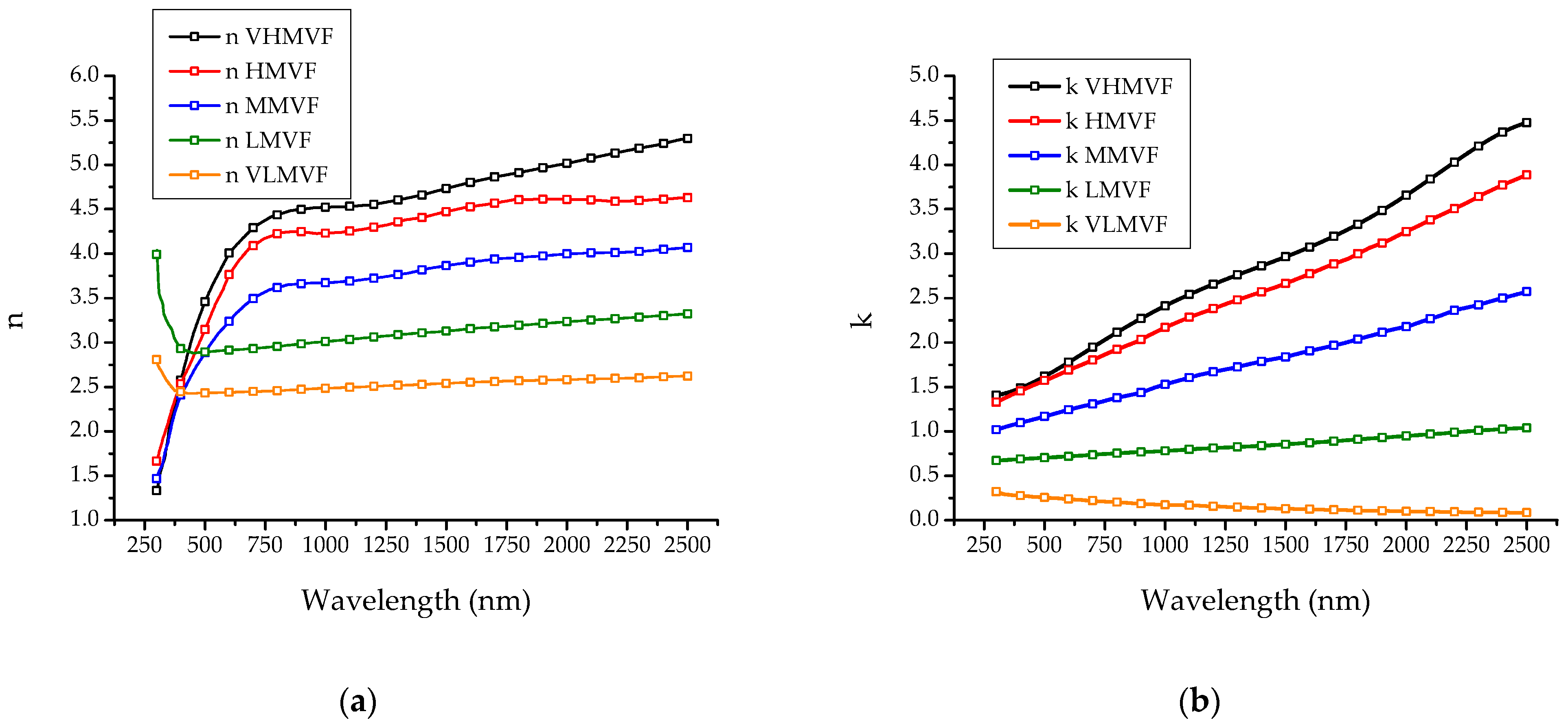
The four cermet samples were deposited and optically characterized
Table 3 reports the corresponding evaluated thickness, whereas
Figure 4 shows the optical parameters estimated by inversion method.
Table 3 and
Figure 4 also report the thickness and the optical parameters of the VLMVF cermet sample used to select the low MVF cermet material of the AR filter design. As can be seen in
Figure 4, the power densities selected for the solar coating design provide cermet materials with optical properties well distributed in a wide range and, therefore, suitable for the design of a graded multilayer cermet. An interpolation method was applied to estimate the optical parameters of cermet materials having intermediate MVF values. A sampling step of the W power density equal to 0.44 W/cm
2 was used to interpolate the optical parameters of the intermediate cermet materials included between the VHMVF and the VLMVF cermet materials.
3.3. AlN and SiO2 Ceramics
The deposition of AlN and SiO2 was carried out through the reactive sputtering technique in transition mode. Both deposition processes were conducted at high Ar flow because in these conditions the intensity of the emission spectral line of the selected element varies slowly and the process control is less complex than those conducted at a lower gas flow.
As mentioned in the previous section, AlN deposition was carried out by controlling the Al emission spectral line because this line showed the highest intensity and the best sensitivity to the target condition variations. Moreover, the same process parameters adopted to deposit the ceramic component of the cermet materials were employed to grow the AlN layer of the AR filter.
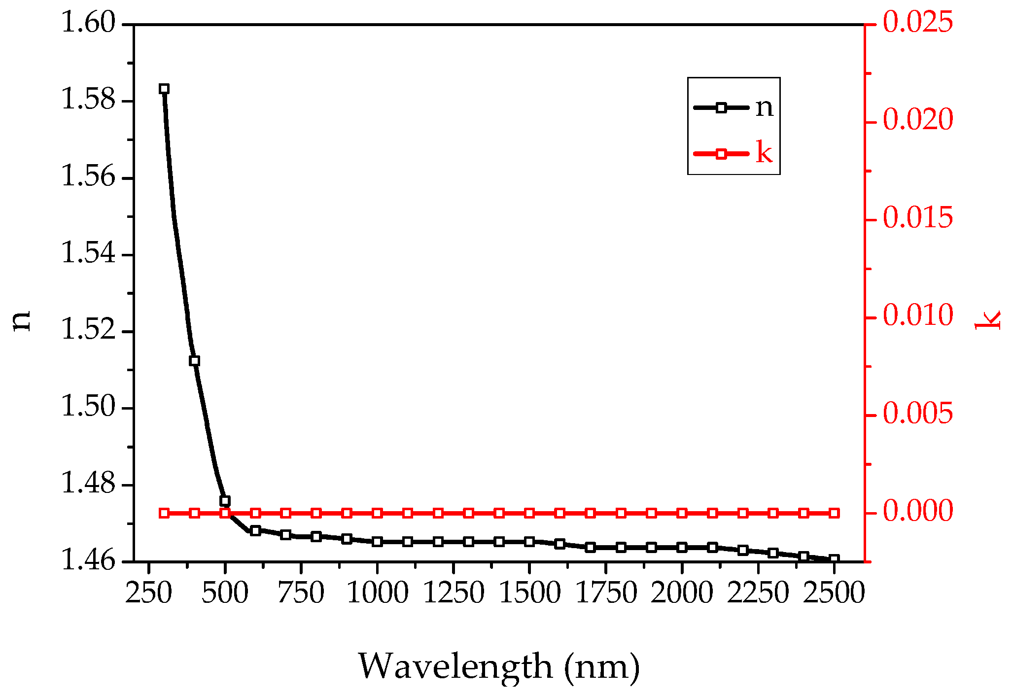
Regarding the SiO
2 deposition, arcing problems encountered during the reactive sputtering in oxygen atmosphere prevented the application of high-density power to Si targets [
57]. Therefore, the deposition of this ceramic was carried out by controlling the O
2 emission spectral line, since it showed the highest intensity and the best sensitivity to target condition variations with the adopted experimental parameters. The SiO
2 film with the expected optical properties of transparency was deposited by fixing the intensity of the emission spectral line of O
2 at 12,000 Cts. The evaluated thickness of the SiO
2 layer was equal to 148 nm; at the same time, the refractive index n and the extinction coefficient k, reported in
Figure 5, show the typical trends of a ceramic material with a good transparency in correspondence to the solar spectrum.
3.4. Design and Manufacturing of the Solar Coating
The optical parameters of all materials were collected in a database and imported in Macleod to design the coating with improved thermal stability. Several reflectance curves were simulated in the spectral range 250–2500 nm by varying the thickness and the metallic profile shape of the graded multilayer cermet, and by combining layers of AlN, SiO2 and low MVF cermet materials with different thicknesses in the AR filter. This filter has been designed to minimize the reflection of solar radiation by exploiting the interferometry technique; the technique is particularly effective in minimizing the reflection of the solar spectrum when the materials included in the filter show significant difference in the refractive indices. In this case, the low MVF cermet material has a higher refractive index than ceramic materials but, at the same time, has a low absorption coefficient, as small metal volumetric fractions are required to obtain significant increases in the refractive index.
Among the structures simulated by Macleod with α
s included in the range 94 ± 0.5%, the design with the cut-off at the lowest wavelength and with the highest slope in the transition region was chosen because it had the lowest thermal emittance value for every operating temperature [
28].
Table 4 reports the design of the solar coating.
This coating was manufactured and the experimental reflectance spectrum was measured by UV-Vis-NIR Lambda 950 spectrophotometer and FTIR spectrometer.
Figure 6 shows the reflectance of the coating characterized by α
s equal to 93.9% and ε
th in the temperature range of 400–550 °C, as reported in
Table 5.
3.5. Durability Study
In this section, the activity performed to predict the coating lifetime is described. Generally, either the direct or indirect approach can be used to estimate the degradation of a solar coating. The direct approach involves the monitoring of chemical, physical and structural modifications of the coating by means of one or more characterization technique (SEM, TEM, AFM, XRD, RAMAN, SIMS, etc.) after each annealing cycle. Conversely, the indirect approach correlates the chemical, physical and structural modifications of coating with the degradation of some parameters, such as the solar absorptance, hemispherical emittance and photo-thermal conversion efficiency [
48,
49,
50,
51,
52,
53]. The method developed by ENEA [
43] is indirect and consists of the identification of the material degradation mechanisms that contribute to the performance deterioration. Once the main degradation mechanisms are identified, the preponderant degradation factors as well as the critical service conditions influencing the lifetime are known too. Therefore, the degradation rate of the performance parameters can be modeled through a mathematical function and the accelerated test can be performed by increasing the stress conditions through the enhancement of the degradation factors in order to reduce the time to failure. It is worth noting that the correctness of the procedure is guaranteed only if the enhanced degradation factor activates the same degradation mechanisms that are associated to the real working conditions of the coating.
In solar coatings, diffusion and other chemical-physical transformations are the predominant mechanisms activated by temperature that cause the photo-thermal parameters degradation. The rate r of these phenomena can be expressed through the Arrhenius law [
48,
49,
51,
52,
53,
58]:
where E
a is the activation energy, R is the universal gas constant and T is the absolute temperature. Assuming that a linear correlation exists between the rate of the degradation mechanisms and the modification rate of the photo-thermal parameters, the degradation rate of the parameters can be modeled through the Arrhenius law.
Six samples of the same coating were subjected to accelerated ageing tests in a programmable oven to estimate the thermal degradation rate of the photo-thermal parameters, according to the operative conditions specified in the experimental section. The parameters adopted to conduct the durability study were α
s and ε
th at 500 °C. The three accelerated tests showed that α
s was constant over time because its modifications were negligible compared to the accuracy of the measurement instruments. Differently, according to the Arrhenius law, Δε
th/Δt was constant over time for each of the three accelerated tests because the difference between the measured value of ε
th and its corresponding value on the interpolation line was lower than the accuracy of the measurement instruments.
Figure 7a–c show ε
th at 500 °C of the two samples subjected to the accelerated test at 620 °C, 650 °C and 690 °C, respectively, while
Figure 7d reports the three averaged ε
th as a function of time. The average values of Δε
th/Δt calculated on each couple of samples were 1.7 10
−3 h
−1 at 620 °C, 4.53 10
−3 h
−1 at 650 °C and 1.9 10
−2 h
−1 at 690 °C.
In order to evaluate the maximum operating temperature of the new coating, a ε
th increase of 1.5% after 25 years of service (8 h/day) was considered as a good indicator of the long-term stability of the coating. Indeed, it causes a reduction of the photo-thermal conversion efficiency lower than 1.3% after 25 years in a conventional CSP plant with the parabolic trough collectors that work at an operating temperature of 500 °C. This degradation value was reported in
Figure 7d and the temporal interval (Δt) needed to reach this degradation was evaluated for each accelerated test. In
Table 6, these temporal intervals are reported versus the temperatures of the accelerated tests.
At this point, the degradation rate of ε
th can be expressed through the Arrhenius law as follows:
where A is the degradation rate constant. If Δt is explicated from Equation (2) and the natural logarithm is computed:
Equation (3) shows that the temporal interval needed to reach a fixed ε
th degradation depends only on the operating temperature and its logarithm, plotted against the reciprocal of the temperature, has a linear trend with a slope equal to the ratio E
a/R.
Figure 8 reports the natural logarithm of Δt needed to reach a ε
th degradation of 1.5% as a function of the reciprocal temperature of each accelerated test. This figure also shows the linear interpolation of these points, which is useful to determine the ratio E
a/R.
Although, in principle, only two accelerated tests would be necessary to estimate Ea, the third test was carried out to verify that the modification rate of εth follows the Arrhenius law in the whole range of temperature 620–690 °C.
The E
a value obtained by the line’s slope in
Figure 8 was 244 kJ/mol and it was used to predict the ε
th coating degradation after 25 years of service for different operating temperatures. The first prediction was performed at the operating temperature of 400 °C. In this case, the ε
th degradation after 25 years of service is 0.003%, a value so low to consider invariant the photo-thermal performance of the manufactured coating during its lifetime. The thermal stability improvement of this new coating is still more evident if its behavior at 400 °C is compared with that of the similar coating developed by using the ENEA technology of the double nitride cermet [
26,
28]. The activation energy of this coating was 140 kJ/mol and the corresponding increase of ε
th was 0.18% after 25 years of service at 400 °C. These data highlight the significant improvement of thermal stability of the new solar coatings. Moreover, it is interesting to observe that a ε
th increase of 0.18% is reached by the new coating only after 25 years at 470 °C.
Finally,
Figure 9 shows the temporal interval needed to reach a ε
th increase of 1.5% as a function of the operating temperature. Here, the line of the 25 years (73,000 h) is also reported and the intersection of this line with the curve of the temporal intervals needed to reach a ε
th increase of 1.5% identifies the maximum operating temperature of the new coating. This maximum operating temperature is equal to 514 °C. The similar coating developed with the technology of double nitride cermet has a ε
th increase of 1.5% after 25 years of service at 463 °C. This result confirms the significant improvement in the stability of the new coating compared to that of similar coatings manufactured by using the previous ENEA technologies.
4. Conclusions
The experimental activity described in this work concerns the manufacturing of a new solar absorber coating, based on an Ag infrared reflector, characterized by high structural and chemical stability under vacuum at high temperature. This new coating was realized through an optimized, high-energy and fast deposition process. The growth of thermally stable Ag infrared reflectors was favored by efficient surface pre-treatments of SS substrate and placing the Ag layer between layers of W and W-AlN, which were more compact and uniform than those of W and WN-AlN developed by ENEA using the double-nitride cermet technology [
26,
28]. An Unbalanced Magnetron cathode was adopted to promote an ion-assisted deposition process that improved uniformity and compactness of the W and W-AlN films with respect to W and WN-AlN films deposited with a standard Magnetron cathode. The high deposition rate was obtained by using the DC sputtering technology to deposit all metallic components and the reactive Magnetron sputtering technology in transition mode with MF supply to grow all ceramic components. The multilayer structure of the optimized solar coating with improved thermal stability is composed of the following layers:
SS/W/Ag/graded cermet (W-AlN)/AR filter (AlN, low MVF cermet, SiO2).
Five cermet samples were manufactured and optically characterized. The refractive index and extinction coefficient of these samples were used to create a database that, along with the Ag, AlN and SiO2 optical parameters, was employed to design the solar coating with improved thermal stability. Hence, the new coating was manufactured according to the optimized design and optically characterized to evaluate αs and εth.
Finally, an investigation method developed by ENEA [
43] was applied to estimate the degradation of the solar coating at different operating temperatures. This method predicts the lifetime of the manufactured solar coatings by accelerated ageing tests conducted at temperatures above the operating ones, with the aim of experimentally simulating the evolution of the coating over the years. As a first interesting result of this activity, no photo-thermal parameter degradation of the new coating could be observed after 25 years of service at an operating temperature of 400 °C. As a second result, the photo-thermal conversion efficiency of the new coating decreases by only 1.5% after 25 years of service at the operating temperature of 514 °C. These findings demonstrate a significant improvement in the long-term thermal stability of the new coating compared to that of similar coatings previously produced by ENEA and justify a further research effort aimed at the identification of more effective structures to stabilize the infrared reflector of Ag. Considering the significant improvement that can be achieved in terms of stability of the tube receiver efficiency through this solar absorber coating, the present results are expected to lead to the reduction of the operative and capital costs of the CSP/CST plants. Indeed, the improved stability and durability of solar coatings will reduce the maintenance costs of the solar field, whereas their enhanced photo-thermal efficiency will impact the solar field global efficiency and, consequently, the solar field size and investment cost.


