
Discrimination of Transformer Inrush Currents and Internal Fault Currents Using Extended Kalman Filter Algorithm (EKF)


Abstract
:1. Introduction
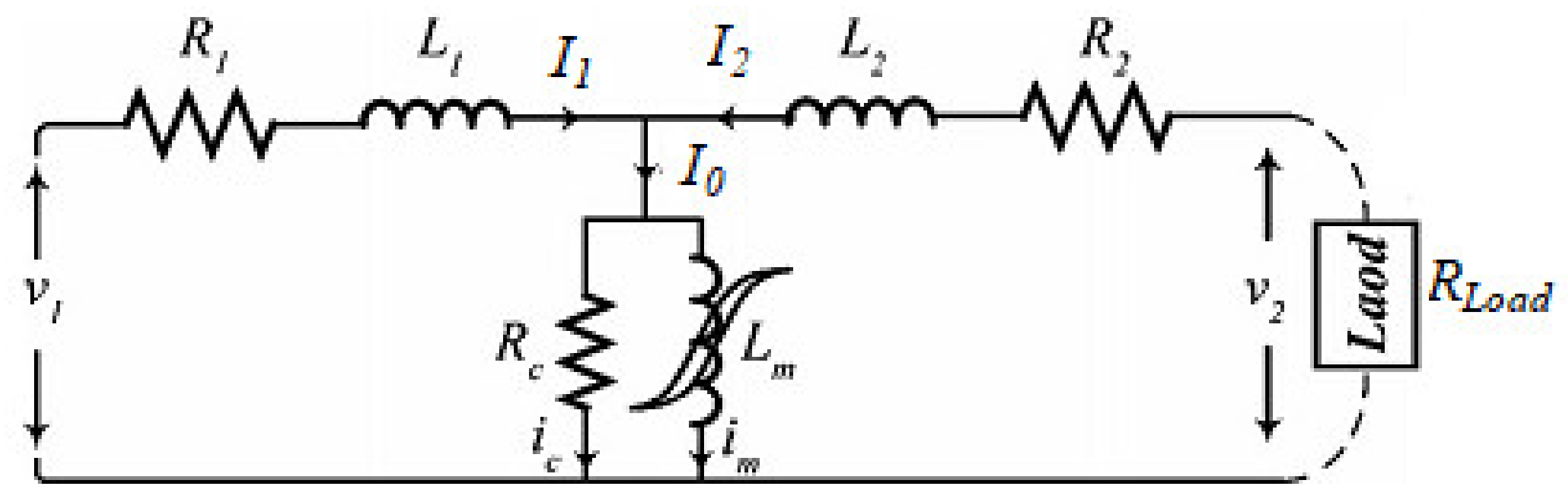
2. Transformer State-Space Nonlinear Model
3. EKF Formulation and Its Working Principle
3.1. Proposed Working Principle of the EKF
3.2. Formation of the EKF
3.3. Operating Criteria
4. Analysis of Simulation Results of Transformer under Various Faults
4.1. Transformer Parameters
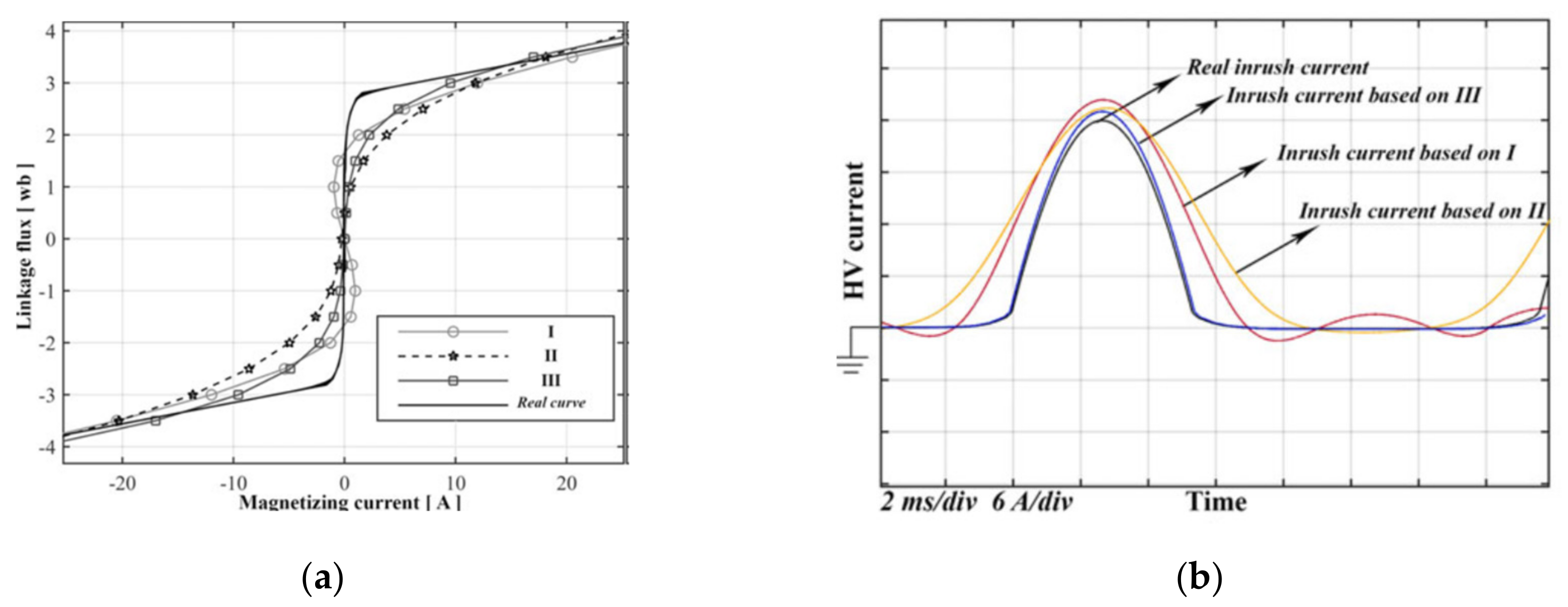
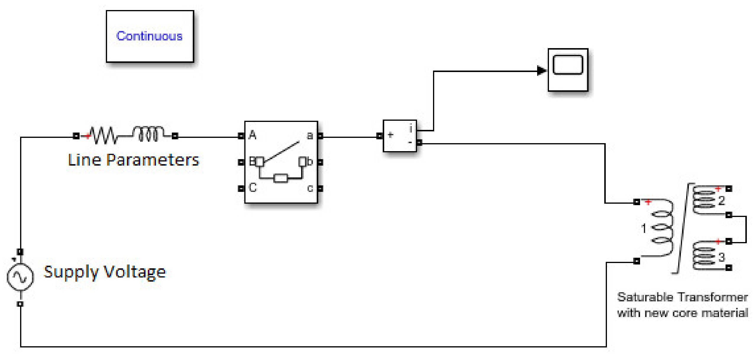
4.2. Types of Inrush Currents, Modeling, and Simulation of Inrush Currents
- Inrush current energization
- Recovery inrush current
- Sympathetic inrush current
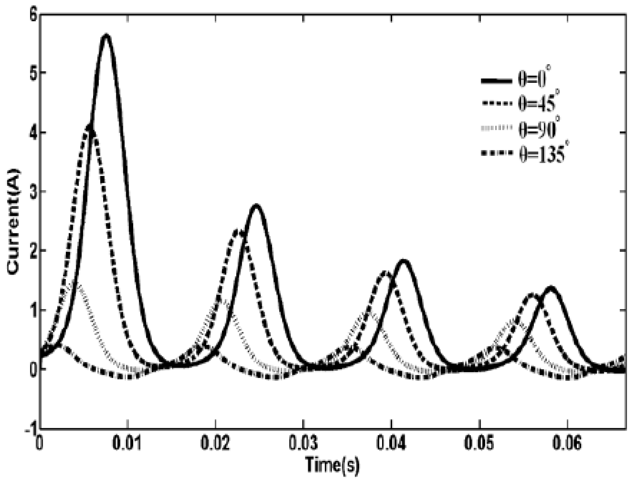
4.2.1. Factors Affecting Inrush Currents
- The switching time of the voltage waveform, when the transformer is energized.
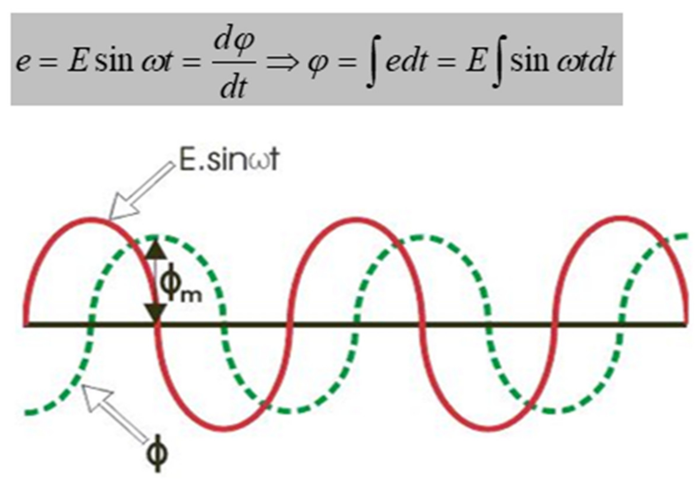
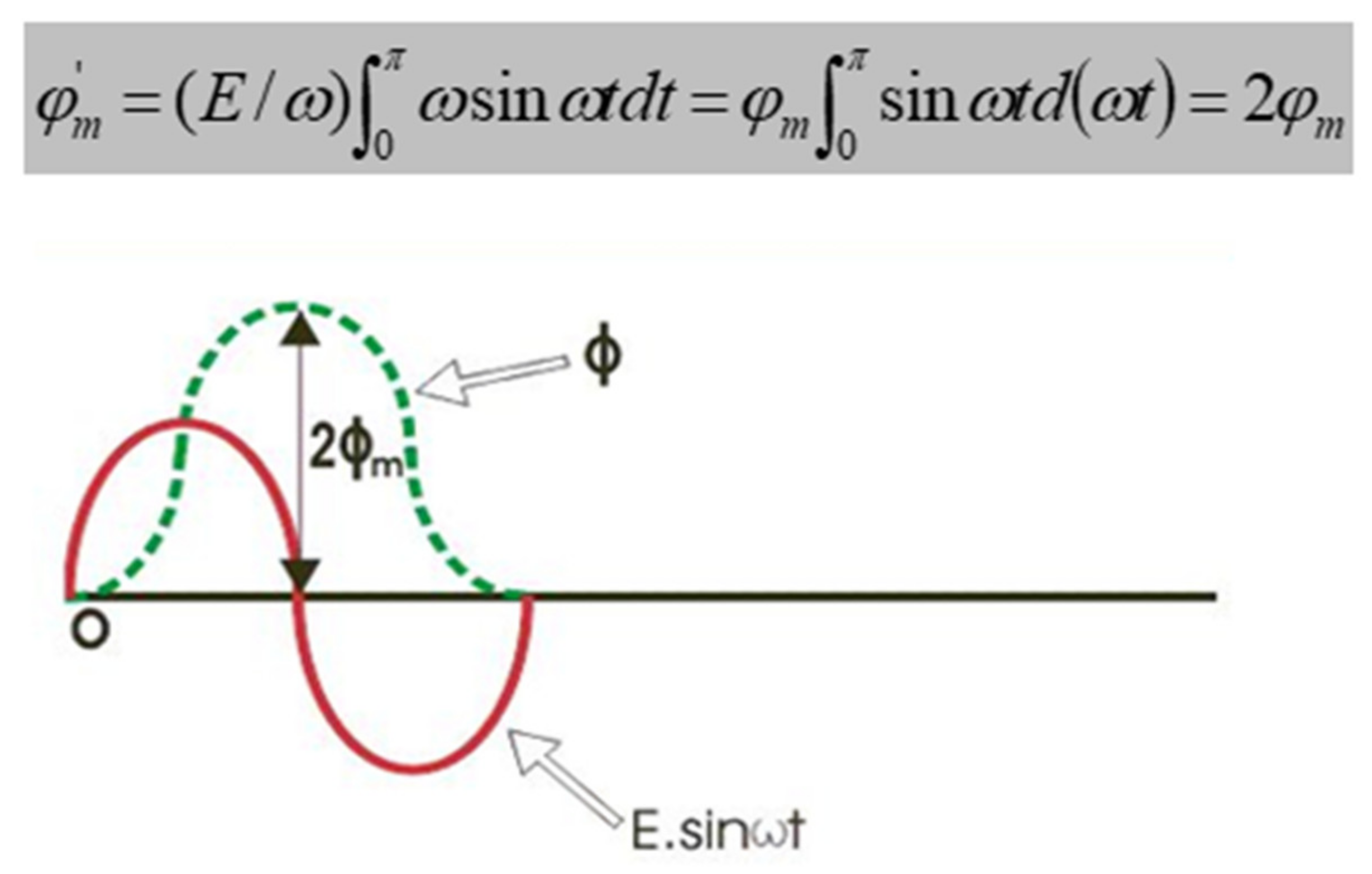
- The magnitude and polarity of the flux (residual) persisting in the transformer at the re-energization time.
- Resistance on the primary side winding.
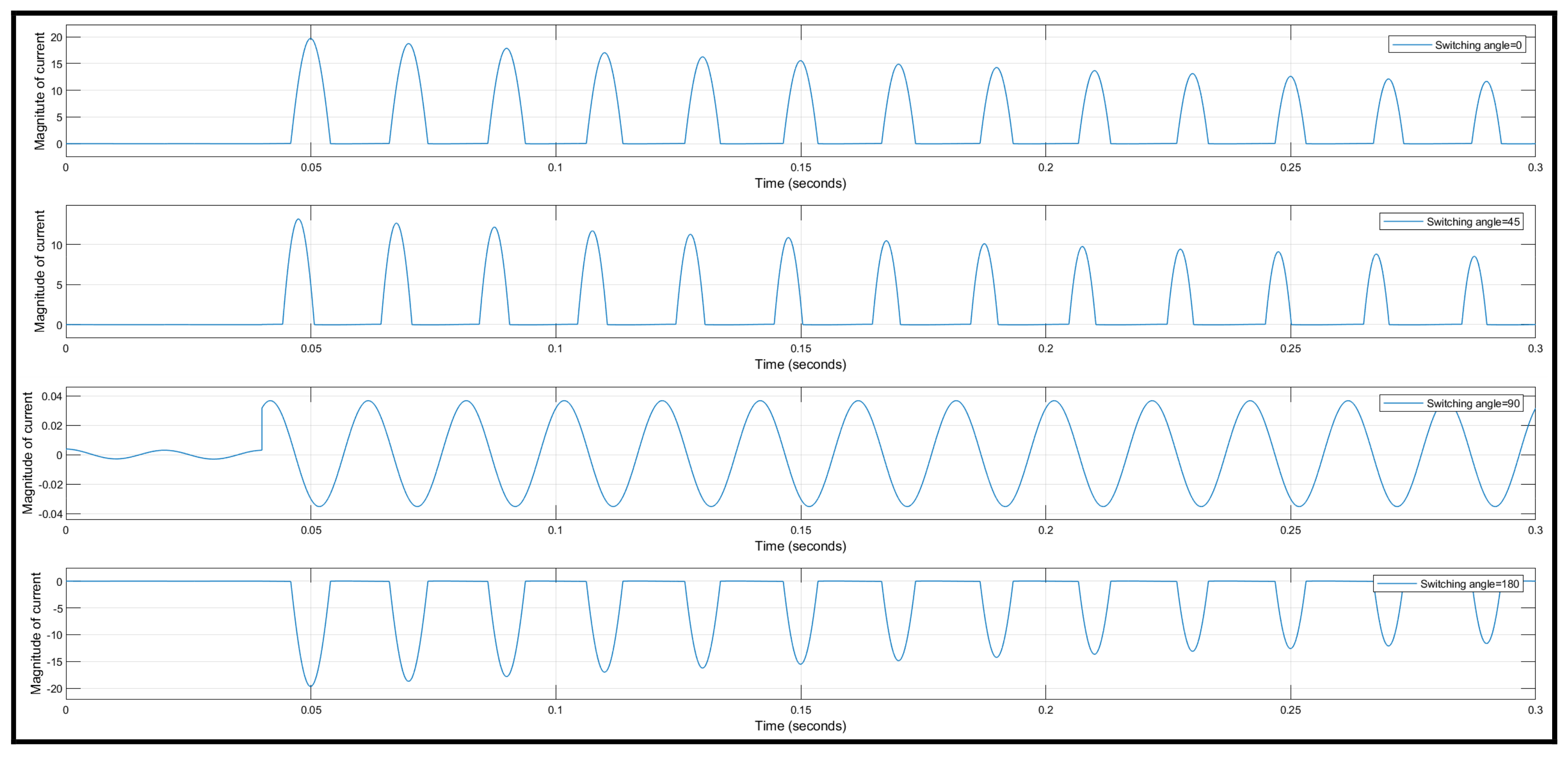
4.2.2. Effects of Switching Angle
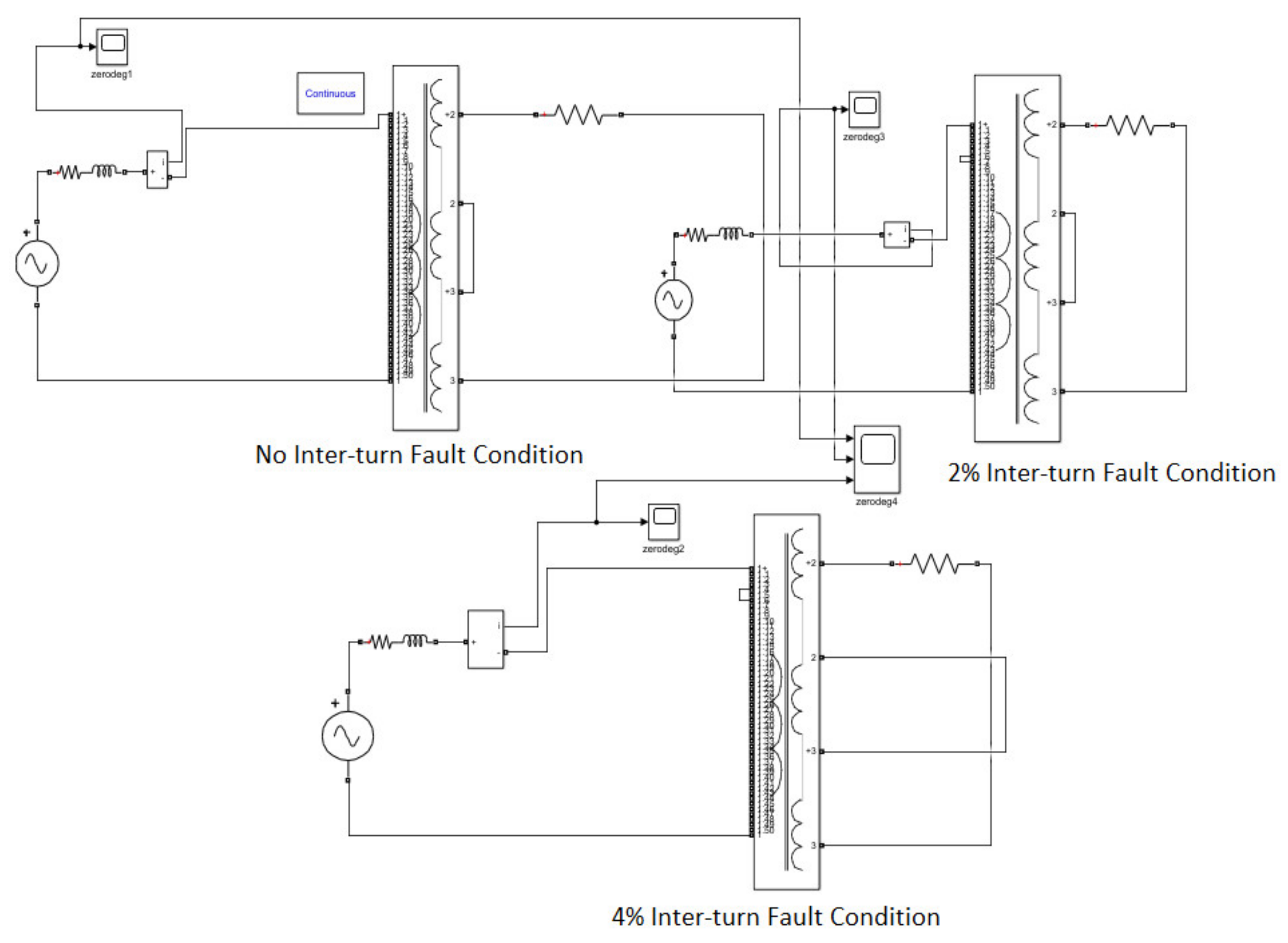
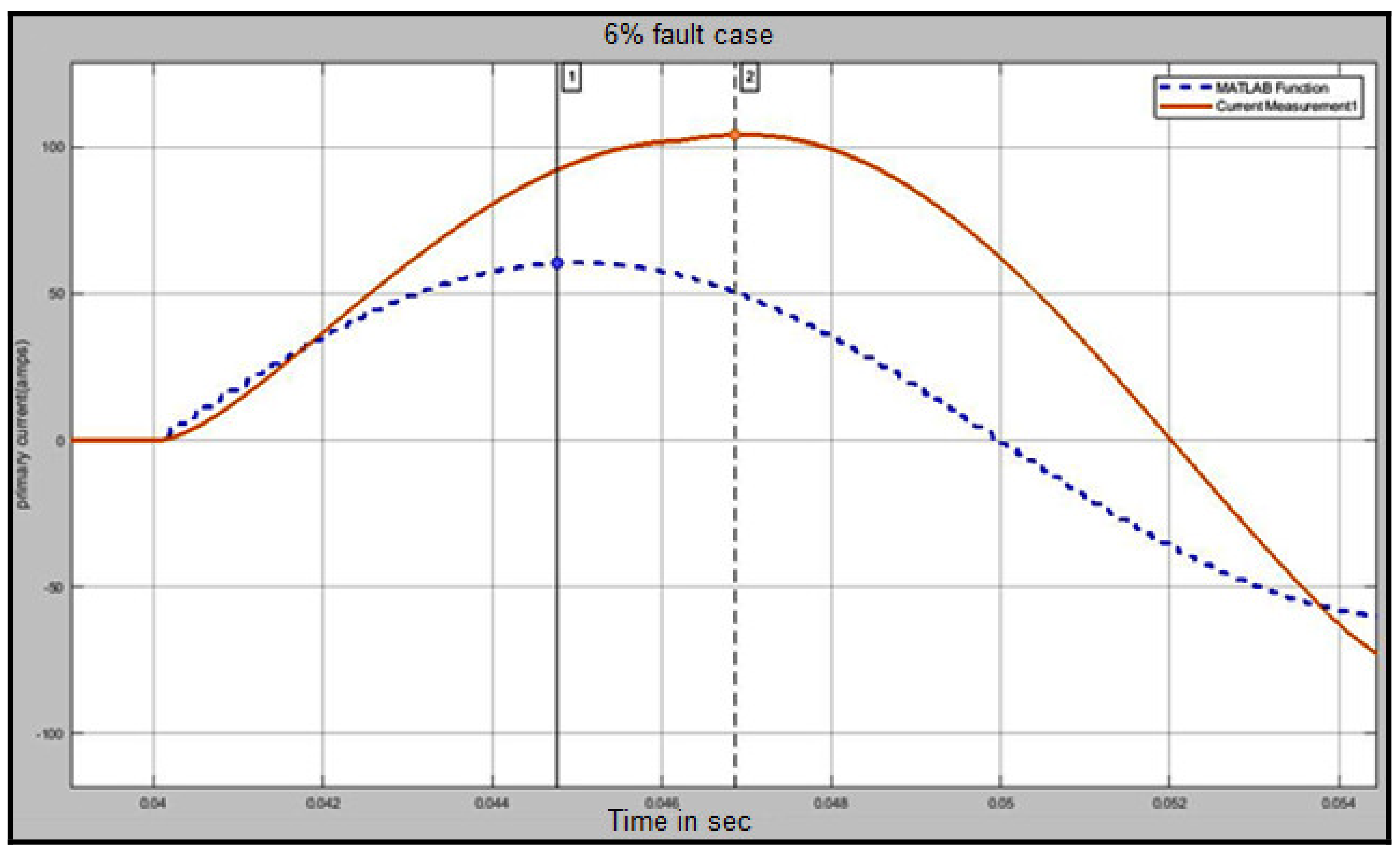
4.3. Modeling and Simulation of Internal Faults
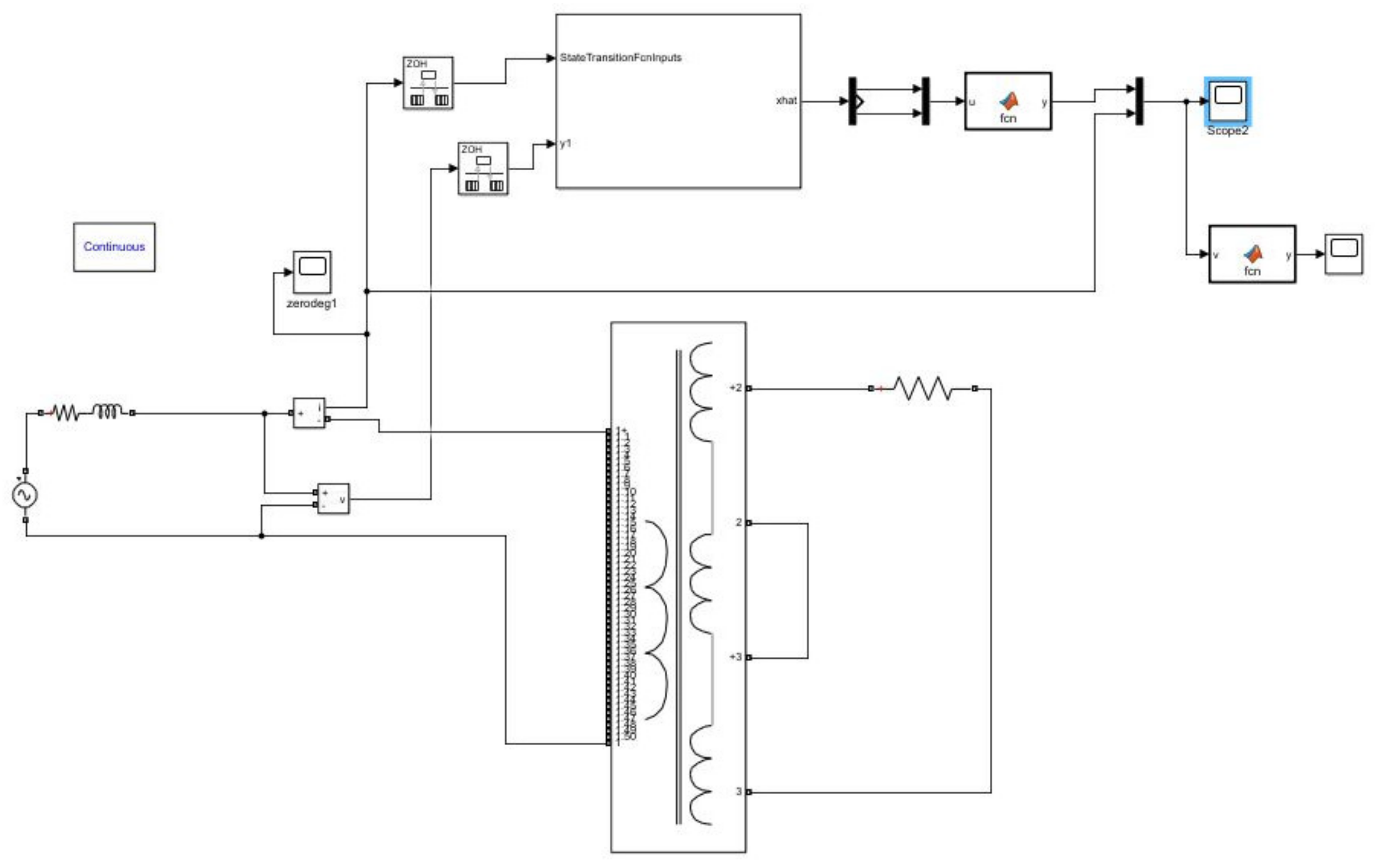
4.4. Implementation of the EKF for the Specified Transformer
dt = 0.0001; ind1 = 0.012256; ind2 = 0.000106; R1 = 2.59; R2 = 2 × 4.6344e-05; RC = 105,000; x = x + [(-R1×x(1)/ind1) + (R1× x(3)/ind1) + v; (-R2× x(2)/ind2) + (R2× x(3)/ind2);RC× x(1)/ind1 + RC× x(2)/ind2 − (RC× x(3)) ×(1/ind1 + 1/ind2)-RC× sign(x(3)) ×(13.89× exp(-((abs(x(3))-6.17)/2.58)^2)) − RC× sign(x(3)) ×(54.55× exp(-((abs(x(3))-6)/1.92)^2))] × dt; end
ind1 = 0.012256; ind2 = 2 × 5.55368e-5; R1 = 2.59; R2 = 2 × 4.6344e-05; RC = 105,000; y = (1/ind1) × x(1) − (1/ind1) × x(3); end |
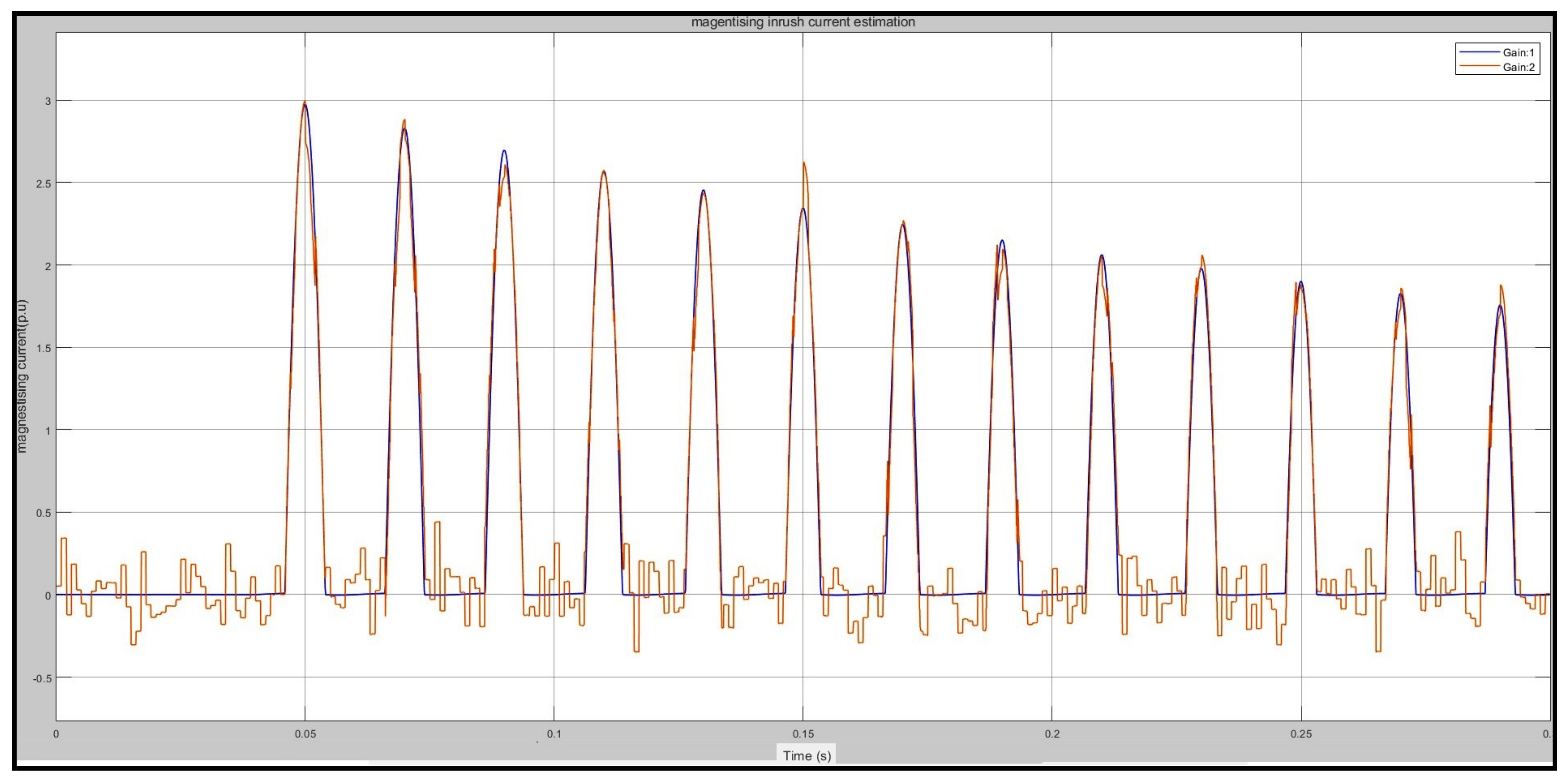
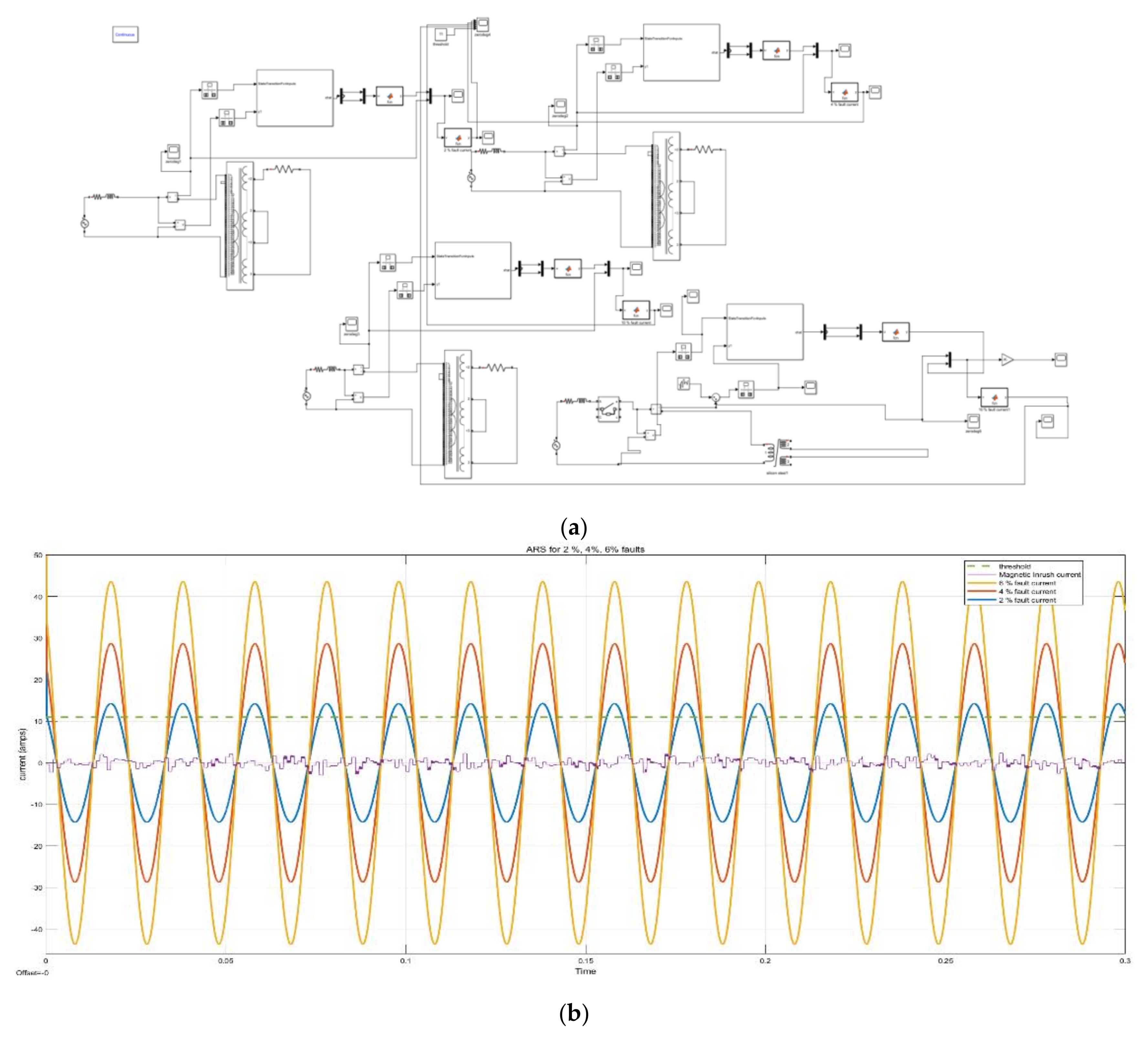
4.5. Simulation Results of EKF Algorithm for Various Conditions
4.6. Observations
- The EKF algorithm was simulated for cases of inrush current with various switching angle cases, and the residue signal was found to be low and within limits (less than the selected threshold value in all cases).
- The internal fault current could not be estimated by the EKF filter and all the ARS values were found to be greater than the selected threshold value of 11 amperes (all fault conditions had an ARS of 11A or more, so this was selected as the threshold). If ARS > 11A, it is an internal fault; otherwise, it is not.
- While we prefer a shorter operating time, some fault cases may be perceived as inrush because the ARS value might not have crossed the threshold by then. Nevertheless, the operating point was always low (max 116 milliseconds, which is much less than a cycle). As the severity of the fault increases, the detection time decreases as the required residual threshold is achieved earlier.
- EKF is independent of the low second harmonic problem as the filter takes into account the BH curve of the core. If the core material or other parameters of the transformers are changed, the equations for the EKF algorithm will have to be changed as well and, hence, the algorithm is able to predict the inrush currents in every case provided the equations are derived and implemented carefully.
- The state-space model and all the coefficients must be derived very carefully. Even a slight mistake can cause the EKF to diverge, which is bound to give the wrong output.
5. Conclusions
Author Contributions
Funding
Institutional Review Board Statement
Informed Consent Statement
Acknowledgments
Conflicts of Interest
References
- Zheng, T.; Yang, X.; Guo, X.; Wang, X.; Zhang, C. Zero-Sequence Differential Current Protection Scheme for Converter Transformer Based on Waveform Correlation Analysis. Energies 2020, 13, 1814. [Google Scholar] [CrossRef] [Green Version]
- Shahabodin, A.; Mousa, A.; Benyamin, P.; Mohammad, M. Integration of Accelerated Deep Neural Network into Power Transformer Differential Protection. IEEE Trans. Ind. Inform. 2020, 16, 865–876. [Google Scholar]
- Gopika, R.; Deepa, S. Study on Power Transformer Inrush Current. IOSR J. Electr. Electron. Eng. 2017, 2, 59–63. [Google Scholar]
- Hassan, A.; Majid, S. A novel technique for internal fault detection of power transformers based on moving windows. Int. Trans.Electr. Energy Syst. 2014, 24, 1263–1278. [Google Scholar]
- Luliang, Z.; Mengshi, L.; Tianyao, J.; Jie, Z. Identifying magnetizing inrush in power transformers based on symmetry of current waveforms. IEEJ Trans. Electr. Electron. Eng. 2017, 12, 959–960. [Google Scholar]
- Bahador, F.; Golshan, M.; Abyaneh, H.; Saghaian-Nejad, M. A runs test-based method for discrimination between internal faults and inrush currents in power transformers. Eur. Trans. Electr. Power 2011, 21, 1392–1408. [Google Scholar]
- Zhang, H.; Wen, J.; Liu, P.; Malik, O. Discrimination between fault and magnetizing inrush current in transformers using short-time correlation transform. Electr. Power Energy Syst. 2002, 24, 557–562. [Google Scholar] [CrossRef]
- Youssef, O. A Wavelet-Based Technique for Discrimination between Faults and Magnetizing Inrush Currents in Transformers. IEEE Trans. Power Deliv. 2003, 18, 170–176. [Google Scholar] [CrossRef]
- Hajipour, E.; Vakilian, M.; Majid, S. Current-Transformer Saturation Compensation for Transformer Differential Relays. IEEE Trans. Power Deliv. 2015, 30, 2293–2302. [Google Scholar] [CrossRef]
- Naseri, F.; Kazemi, Z.; Arefi, M.; Farjah, E. Fast Discrimination of Transformer Magnetizing Current from Internal Faults: An Extended Kalman Filter-Based Approach. IEEE Trans. Power Deliv. 2018, 33, 110–118. [Google Scholar] [CrossRef]
- Ma, J.; Wang, Z.; Yang, Q.; Liu, Y. A Two Terminal Network-Based Method for Discrimination between Internal Faults and Inrush Currents. IEEE Trans. Power Deliv. 2010, 25, 1599–1605. [Google Scholar] [CrossRef]
- Sahebi, A.; Samet, H. Discrimination between internal fault and magnetising inrush currents of power transformers in the presence of a superconducting fault current limiter applied to the neutral point. IET Sci. Meas. Technol. 2016, 10, 537–544. [Google Scholar] [CrossRef]
- Bagheri, S.; Moravej, Z.; Gharehpetian, G. Classification and Discrimination among Winding Mechanical Defects, Internal and External Electrical Faults, and Inrush Current of Transformer. IEEE Trans. Ind. Inform. 2018, 14, 484–493. [Google Scholar] [CrossRef]
- Faiz, J.; Lotfi-Fard, S. A Novel Wavelet-Based Algorithm for Discrimination of Internal Faults from Magnetizing Inrush Currents in Power Transformers. IEEE Trans. Power Deliv. 2006, 21, 1989–1996. [Google Scholar] [CrossRef]
- Eissa, M. A Novel Digital Directional Transformer Protection Technique Based on Wavelet Packet. IEEE Trans. Power Deliv. 2005, 20, 1830–1836. [Google Scholar] [CrossRef]
- Ahmadi, M.; Samet, H.; Ghanbari, T. Discrimination of internal fault from magnetizing inrush current in power transformers based on sine-wave least-squares curve fitting method. IET Sci. Meas. Technol. 2014, 9, 73–84. [Google Scholar] [CrossRef]
- Hongtian, C.; Bin, J. A Review of Fault Detection and Diagnosis for the Traction System in High-Speed Trains. IEEE Trans. Intell. Transp. Syst. 2020, 21, 450–465. [Google Scholar]
- Chao, C.; Wang, W.; Chen, H.; Zhang, B.; Shao, J.; Teng, W. Enhanced Fault Diagnosis Using Broad Learning for Traction Systems in High-Speed Trains. IEEE Trans. Power Electron. 2021, 36, 7461–7469. [Google Scholar]
- Thote, P.; Daigavane, M.; Daigavane, P.; Gawande, S. An Intelligent Hybrid Approach Using KNN-GA to Enhance the Performance of Digital Protection Transformer Scheme. Can. J. Electr. Comput. Eng. 2017, 40, 151–161. [Google Scholar]
- Batista, Y.; Souza, H.; Santos Neves, F.; Dias Filho, R. A GDSC-Based Technique to Distinguish Transformer Magnetizing from Fault Currents. IEEE Trans. Power Deliv. 2018, 33, 589–599. [Google Scholar] [CrossRef]
- Li, C.; Zhou, N.; Liao, J.; Wang, Q. Multiscale multivariate fuzzy entropy-based technique to distinguish transformer magnetising from fault currents. IET Gener. Transm. Distrib. 2019, 13, 2319–2327. [Google Scholar] [CrossRef]
- Shah, A.; Bhalja, B. Fault discrimination scheme for power transformer using random forest technique. IET Gener. Transm. Distrib. 2016, 10, 1431–1439. [Google Scholar] [CrossRef]


| No | Function | RMSE |
|---|---|---|
| I | 1.1082 | |
| II | 1.3214 | |
| III | 0.7042 |
| Specification No. | Parameters | Value |
|---|---|---|
| 1 | KVA rating | 15 KVA |
| 2 | Frequency | 50 Hz |
| 3 | Voltage Rating | 2300/230 |
| 4 | Rated Primary Current | 6.53 amps |
| 5 | Winding Resistance on Primary | 7.334 mΩ |
| 6 | Winding Resistance on Secondary | 4.634 × 10⁻⁵ Ω |
| 7 | Winding Reactance on Primary | 3.428 Ω |
| 8 | Winding Reactance on Secondary | 6.194 Ω |
| SNo. | Switching Angle | Inrush Current Magnitude |
|---|---|---|
| 1 | 0 degree switching | 19.688 A |
| 2 | 45 degree switching | 13.170 A |
| 3 | 90 degree switching | 0.037 A |
| 4 | 180 degree switching | −19.573 A |
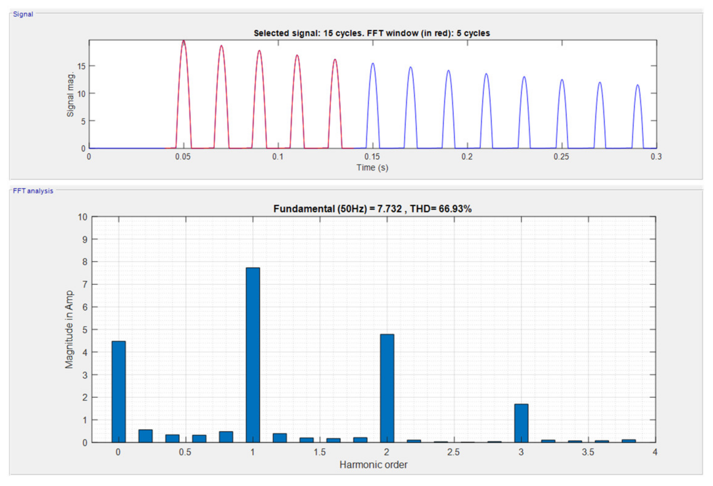
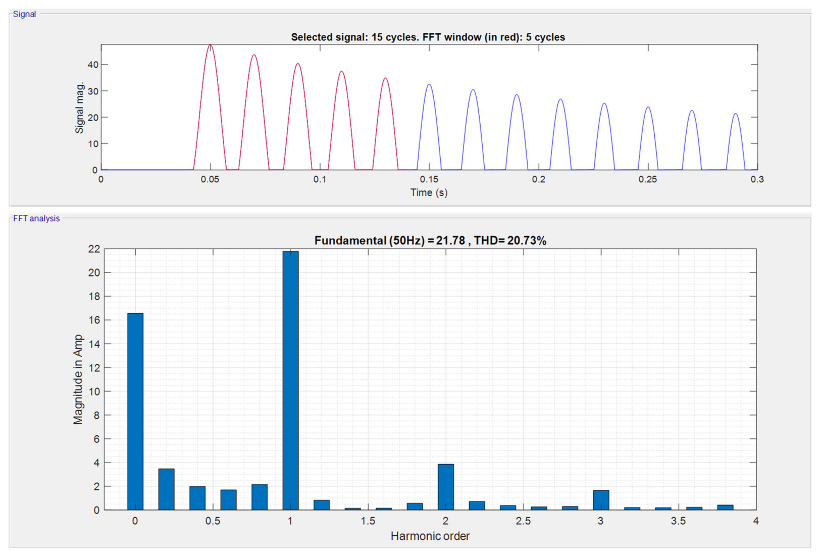
| Sl.No. | Harmonic Oder | Old Materials | New Materials (Metglass) |
|---|---|---|---|
| 1 | Fundamental harmonic (1st) magnitude | 7.73 A | 21.78 A |
| 2 | 2nd harmonic magnitude | 4.78 A | 3.86 A |
| 3 | 3rd harmonic magnitude | 1.69 A | 1.65 A |
| 4 | Total harmonic distortion (%THD) | 66.93% | 20.73% |
| Sl.No. | Particulars | No Fault | 2% Fault | 4% Fault |
|---|---|---|---|---|
| 1 | Current Magnitude (RMS value) (Simulation analysis) | 6.52 A | 20.23 A | 34.48 A |
| 2 | Current Magnitude (Peak = RMS × 1.414 value) (Simulation analysis) | 9.151 A | 28.226 A | 47.666 A |
| 3 | Current Magnitude (Peak = RMS × 1.414 value) (Mathematical analysis) | 9.21 A | 28.61 A | 48.854 A |
| S.No. | Different Cases | ARS Signal Amplitude (amps) | Detection Time (ms) |
|---|---|---|---|
| 1 | For all inrush currents | less than 5 amps | - |
| 2 | Threshold value | 11 amps | - |
| 3 | Energization with 2% fault | 14.3 amps | 116 |
| 4 | Energization with 4% fault | 28.82 amps | 115 |
| 5 | Energization with 6% fault | 43.82 amps | 114 |
Publisher’s Note: MDPI stays neutral with regard to jurisdictional claims in published maps and institutional affiliations. |
© 2021 by the authors. Licensee MDPI, Basel, Switzerland. This article is an open access article distributed under the terms and conditions of the Creative Commons Attribution (CC BY) license (https://creativecommons.org/licenses/by/4.0/).
Share and Cite
Gunda, S.K.; Dhanikonda, V.S.S.S.S. Discrimination of Transformer Inrush Currents and Internal Fault Currents Using Extended Kalman Filter Algorithm (EKF). Energies 2021, 14, 6020. https://doi.org/10.3390/en14196020
Gunda SK, Dhanikonda VSSSS. Discrimination of Transformer Inrush Currents and Internal Fault Currents Using Extended Kalman Filter Algorithm (EKF). Energies. 2021; 14(19):6020. https://doi.org/10.3390/en14196020
Chicago/Turabian StyleGunda, Sunil Kumar, and Venkata Samba Sesha Siva Sarma Dhanikonda. 2021. "Discrimination of Transformer Inrush Currents and Internal Fault Currents Using Extended Kalman Filter Algorithm (EKF)" Energies 14, no. 19: 6020. https://doi.org/10.3390/en14196020
APA StyleGunda, S. K., & Dhanikonda, V. S. S. S. S. (2021). Discrimination of Transformer Inrush Currents and Internal Fault Currents Using Extended Kalman Filter Algorithm (EKF). Energies, 14(19), 6020. https://doi.org/10.3390/en14196020