
Review of Technologies and Recent Advances in Low-Temperature Sorption Thermal Storage Systems


Abstract
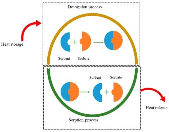
1. Introduction
2. Materials for Low-Temperature Sorption Heat Storage Systems
- Products with small molar volumes for compact design
- High sorption properties
- Maximum energy density at operating temperatures
- Small volume changes during reactions
- High thermal conductivity
- Low regeneration time
- High heat and mass transport of the sorbent/sorbate
- Non-corrosive and non-flammable nature
- High reaction output during charging and discharging
- Non-irritating environment
2.1. Liquid Absorption Materials
2.1.1. Salts, Salt Hydrates, and Ammonia-Water Based Working Pairs
2.1.2. Ionic Liquids for Absorption TES System
2.2. Solid Adsorption Materials
2.2.1. Zeolites/H2O
2.2.2. Silica Gel/H2O
2.2.3. Novel Porous Materials
2.3. Chemical Reaction Materials
2.4. Composite Materials
3. Advances in Absorption TES Systems
3.1. Long-Term Cycles for Absorption TES Systems
3.2. Solar-Driven Absorption Cycle-Integrated Thermal Storage
3.3. Compression-Driven Absorption Cycle Integrated Thermal Storage
3.4. Double-Stage Absorption Cycle
4. Designs for Low-Temperature TES Systems
4.1. Open and Closed Systems
4.2. Reactor Design
4.3. Thermal Conductivity and Mass Transfer in the Reactor
5. Developed Prototypes and Systems for Thermal Energy Storage
6. Conclusions
7. Future Outlook
Author Contributions
Funding
Institutional Review Board Statement
Informed Consent Statement
Data Availability Statement
Conflicts of Interest
References
- Narayanan, A.; Mets, K.; Strobbe, M.; Develder, C. Feasibility of 100% renewable energy-based electricity production for cities with storage and flexibility. Renew. Energy 2018, 134, 698–709. [Google Scholar] [CrossRef]
- Energy Information Administration.Future Global Energy Demand: Up, Up, and Away! Available online: https://www.globalenergyinstitute.org/future-global-energy-demand-and-away (accessed on 5 May 2021).
- De Matteis, A. Decomposing the anthropogenic causes of climate change. Environ. Dev. Sustain. 2017, 21, 165–179. [Google Scholar] [CrossRef]
- Larcher, D.; Tarascon, J.-M. Towards greener and more sustainable batteries for electrical energy storage. Nat. Chem. 2014, 7, 19–29. [Google Scholar] [CrossRef] [PubMed]
- Sharafeldin, M.; Gróf, G. Experimental investigation of flat plate solar collector using CeO2-water nanofluid. Energy Convers. Manag. 2018, 155, 32–41. [Google Scholar] [CrossRef]
- K/bidi, F.; Damour, C.; Grondin, D.; Hilairet, M.; Benne, M. Power Management of a Hybrid Micro-Grid with Photovoltaic Production and Hydrogen Storage. Energies 2021, 14, 1628. [Google Scholar] [CrossRef]
- Boldoo, T.; Ham, J.; Kim, E.; Cho, H. Review of the Photothermal Energy Conversion Performance of Nanofluids, Their Applications, and Recent Advances. Energies 2020, 13, 5748. [Google Scholar] [CrossRef]
- Tian, Y.; Zhao, C. A review of solar collectors and thermal energy storage in solar thermal applications. Appl. Energy 2012, 104, 538–553. [Google Scholar] [CrossRef]
- Howlader, H.O.R.; Adewuyi, O.B.; Hong, Y.-Y.; Mandal, P.; Hemeida, A.M.; Senjyu, T. Energy Storage System Analysis Review for Optimal Unit Commitment. Energies 2019, 13, 158. [Google Scholar] [CrossRef]
- NREL. Solar Thermal Energy Storage Projects. Available online: https://solarpaces.nrel.gov/by-status/operational (accessed on 7 May 2021).
- Lin, J.; Zhao, Q.; Huang, H.; Mao, H.; Liu, Y.; Xiao, Y. Applications of low-temperature thermochemical energy storage systems for salt hydrates based on material classification: A review. Sol. Energy 2020, 214, 149–178. [Google Scholar] [CrossRef]
- Stutz, B.; Le Pierrès, N.; Kuznik, F.; Johannes, K.; Del Barrio, E.P.; Bédécarrats, J.-P.; Gibout, S.; Marty, P.; Zalewski, L.; Soto, J.; et al. Storage of thermal solar energy. Comptes Rendus Phys. 2017, 18, 401–414. [Google Scholar] [CrossRef]
- Sarbu, I.; Sebarchievici, C. A Comprehensive Review of Thermal Energy Storage. Sustainability 2018, 10, 191. [Google Scholar] [CrossRef]
- Cabeza, L.; Martorell, I.; Miró, L.; Fernández, A.; Barreneche, C. Introduction to thermal energy storage (TES) systems. In Advances in Thermal Energy Storage Systems; Cabeza, L.F., Ed.; Woodhead Publishing: Sawston, UK, 2015; pp. 1–28. [Google Scholar] [CrossRef]
- de Gracia, A.; Cabeza, L.F. Phase change materials and thermal energy storage for buildings. Energy Build. 2015, 103, 414–419. [Google Scholar] [CrossRef]
- Rao, C.R.; Niyas, H.; Muthukumar, P. Performance tests on lab–scale sensible heat storage prototypes. Appl. Therm. Eng. 2018, 129, 953–967. [Google Scholar] [CrossRef]
- Mesquita, L.; McClenahan, D.; Thornton, J.; Carriere, J.; Wong, B. Drake Landing Solar Community: 10 Years of Operation. In Proceedings of the ISES Conference Proceedings, Durham, NC, USA, 23–25 November 2017. [Google Scholar] [CrossRef]
- IEA. Available online: http://task54.iea-shc.org/Data/Sites/1/publications/A12-Info-Sheet--Ref-SF-SDHW-System--Denmark.pdf (accessed on 15 May 2021).
- IEA. Available online: http://task54.iea-shc.org/Data/Sites/1/publications/A16-Info-Sheet--Ref-MF-Drainback-SDHW--France.pdf (accessed on 15 May 2021).
- Kim, M.-H.; Kim, D.; Heo, J.; Lee, D.-W. Techno-economic analysis of hybrid renewable energy system with solar district heating for net zero energy community. Energy 2019, 187. [Google Scholar] [CrossRef]
- Launay, S.; Kadoch, B.; Le Métayer, O.; Parrado, C. Analysis strategy for multi-criteria optimization: Application to inter-seasonal solar heat storage for residential building needs. Energy 2018, 171, 419–434. [Google Scholar] [CrossRef]
- Ghaebi, H.; Bahadori, M.; Saidi, M. Performance analysis and parametric study of thermal energy storage in an aquifer coupled with a heat pump and solar collectors, for a residential complex in Tehran, Iran. Appl. Therm. Eng. 2014, 62, 156–170. [Google Scholar] [CrossRef]
- Thermal Energy Stoarge. Available online: https://iea-etsap.org/E-TechDS/PDF/E17IR%20ThEnergy%20Stor_AH_Jan2013_final_GSOK.pdf (accessed on 15 May 2021).
- Khan, M.M.A.; Saidur, R.; Al-Sulaiman, F.A. A review for phase change materials (PCMs) in solar absorption refrigeration systems. Renew. Sustain. Energy Rev. 2017, 76, 105–137. [Google Scholar] [CrossRef]
- Mofijur, M.; Mahlia, T.M.I.; Silitonga, A.S.; Ong, H.C.; Silakhori, M.; Hasan, M.H.; Putra, N.; Rahman, S.M.A. Phase Change Materials (PCM) for Solar Energy Usages and Storage: An Overview. Energies 2019, 12, 3167. [Google Scholar] [CrossRef]
- Veerakumar, C.; Sreekumar, A. Phase change material based cold thermal energy storage: Materials, techniques and applications—A review. Int. J. Refrig. 2016, 67, 271–289. [Google Scholar] [CrossRef]
- Alva, G.; Liu, L.; Huang, X.; Fang, G. Thermal energy storage materials and systems for solar energy applications. Renew. Sustain. Energy Rev. 2017, 68, 693–706. [Google Scholar] [CrossRef]
- Kerskes, H.; Mette, B.; Bertsch, F.; Asenbeck, S.; Drück, H. Chemical energy storage using reversible solid/gas-reactions (CWS)—results of the research project. Energy Proc. 2012, 30, 294–304. [Google Scholar] [CrossRef]
- Prasad, J.S.; Muthukumar, P.; Desai, F.; Basu, D.N.; Rahman, M.M. A critical review of high-temperature reversible thermochemical energy storage systems. Appl. Energy 2019, 254. [Google Scholar] [CrossRef]
- N’Tsoukpoe, K.E.; Liu, H.; Le Pierrès, N.; Luo, L. A review on long-term sorption solar energy storage. Renew. Sustain. Energy Rev. 2009, 13, 2385–2396. [Google Scholar] [CrossRef]
- Revankar, S.T. Chapter Six—Chemical Energy Storage. In Storage and Hybridization of Nuclear Energy; Bindra, H., Revankar, S., Eds.; Academic Press: Cambridge, MA, USA, 2019; pp. 177–227. [Google Scholar]
- Ding, Y.; Riffat, S. Thermochemical energy storage technologies for building applications: A state-of-the-art review. Int. J. Low-Carbon Technol. 2012, 8, 106–116. [Google Scholar] [CrossRef]
- Yu, N.; Wang, R.; Wang, L. Sorption thermal storage for solar energy. Prog. Energy Combust. Sci. 2013, 39, 489–514. [Google Scholar] [CrossRef]
- Lefebvre, D.; Tezel, F.H. A review of energy storage technologies with a focus on adsorption thermal energy storage processes for heating applications. Renew. Sustain. Energy Rev. 2017, 67, 116–125. [Google Scholar] [CrossRef]
- Dicaire, D.; Tezel, F.H. Regeneration and efficiency characterization of hybrid adsorbent for thermal energy storage of excess and solar heat. Renew. Energy 2011, 36, 986–992. [Google Scholar] [CrossRef]
- Stanciu, C.; Stanciu, D.; Gheorghian, A.-T. Thermal Analysis of a Solar Powered Absorption Cooling System with Fully Mixed Thermal Storage at Startup. Energies 2017, 10, 72. [Google Scholar] [CrossRef]
- Gores, J.C. Compact Thermal Storage A-State-of-the-Art Review of Experimental Results. Master’s Thesis, Universitat de Lleida, Lleida, Spain, 2011. [Google Scholar]
- Yu, N.; Wang, R.; Lu, Z.; Wang, L. Study on consolidated composite sorbents impregnated with LiCl for thermal energy storage. Int. J. Heat Mass Transf. 2015, 84, 660–670. [Google Scholar] [CrossRef]
- Aristov, Y.I. New family of solid sorbents for adsorptive cooling: Material scientist approach. J. Eng. Thermophys. 2007, 16, 63–72. [Google Scholar] [CrossRef]
- Aydin, D.; Casey, S.P.; Riffat, S. The latest advancements on thermochemical heat storage systems. Renew. Sustain. Energy Rev. 2015, 41, 356–367. [Google Scholar] [CrossRef]
- Lele, A.F.; N’Tsoukpoe, K.E.; Osterland, T.; Kuznik, F.; Ruck, W.K. Thermal conductivity measurement of thermochemical storage materials. Appl. Therm. Eng. 2015, 89, 916–926. [Google Scholar] [CrossRef]
- Bales, C.; Gantenbein, P.; Hauer, A.; Henning, H.-M.; Jaenig, D.; Kerskes, H.; Núñez, T.; Visscher, K. Thermal properties of materials for thermo-chemical storage of solar heat. IEA-SHC Task 2005, 32. [Google Scholar]
- Sun, J.; Fu, L.; Zhang, S. A review of working fluids of absorption cycles. Renew. Sustain. Energy Rev. 2012, 16, 1899–1906. [Google Scholar] [CrossRef]
- N’Tsoukpoe, K.E.; Le Pierrès, N.; Luo, L. Experimentation of a LiBr–H2O absorption process for long-term solar thermal storage: Prototype design and first results. Energy 2013, 53, 179–198. [Google Scholar] [CrossRef]
- Ren, J.; Qian, Z.; Yao, Z.; Gan, N.; Zhang, Y. Thermodynamic Evaluation of LiCl-H2O and LiBr-H2O Absorption Refrigeration Systems Based on a Novel Model and Algorithm. Energies 2019, 12, 3037. [Google Scholar] [CrossRef]
- Dudita, M.; Daguenet-Frick, X.; Gantenbein, P. Closed Sorption Seasonal Thermal Energy Storage with Aqueous Sodium Hydroxide. In Nearly Zero Energy Communities; Springer: Cham, Switzerland, 2017; pp. 239–246. [Google Scholar] [CrossRef]
- Yang, Q.C. Study on LiBr-H2O Absorption Refrigeration System with Integral Storage. Adv. Mater. Res. 2014, 953–954, 752–756. [Google Scholar] [CrossRef]
- Fumey, B.; Weber, R.; Gantenbein, P.; Daguenet-Frick, X.; Stoller, S.; Fricker, R.; Dorer, V.; Fumey, B.; Weber, R.; Gantenbein, P.; et al. Operation Results of a Closed Sorption Heat Storage Prototype. Energy Proc. 2015, 73, 324–330. [Google Scholar] [CrossRef]
- Berlitz, T.; Lemke, N.; Satzger, P.; Ziegler, F. Cooling machine with integrated cold storage. Int. J. Refrig. 1998, 21, 157–161. [Google Scholar] [CrossRef]
- Xu, S.; Huang, X.; Du, R. An investigation of the solar powered absorption refrigeration system with advanced energy storage technology. Sol. Energy 2011, 85, 1794–1804. [Google Scholar] [CrossRef]
- Xiong, Z.; Dai, Y.; Wang, R. Development of a novel two-stage liquid desiccant dehumidification system assisted by CaCl2 solution using exergy analysis method. Appl. Energy 2010, 87, 1495–1504. [Google Scholar] [CrossRef]
- Kessling, W.; Laevemann, E.; Peltzer, M. Energy storage in open cycle liquid desiccant cooling systems. Int. J. Refrig. 1998, 21, 150–156. [Google Scholar] [CrossRef]
- Zhao, Y.; Wang, R.; Li, T.; Nomura, Y. Investigation of a 10 kWh sorption heat storage device for effective utilization of low-grade thermal energy. Energy 2016, 113, 739–747. [Google Scholar] [CrossRef]
- Xu, S.; Zhang, L.; Liang, J.; Du, R. Variable mass energy transformation and storage (VMETS) system using NH3–H2O as working fluid. Part 2: Modeling and simulation under partial storage strategy. Energy Convers. Manag. 2007, 48, 27–39. [Google Scholar] [CrossRef]
- Lima, A.A.S.; Leite, G.d.N.P.; Ochoa, A.A.V.; Dos Santos, C.A.C.; Da Costa, J.A.P.; Michima, P.S.A.; Caldas, A.M.A. Absorption Refrigeration Systems Based on Ammonia as Refrigerant Using Different Absorbents: Review and Applications. Energies 2020, 14, 48. [Google Scholar] [CrossRef]
- Hui, L.; Edem, N.K.; Nolwenn, L.P.; Lingai, L. Evaluation of a seasonal storage system of solar energy for house heating using different absorption couples. Energy Convers. Manag. 2011, 52, 2427–2436. [Google Scholar] [CrossRef]
- Rogers, R.D. CHEMISTRY: Ionic Liquids--Solvents of the Future? Science 2003, 302, 792–793. [Google Scholar] [CrossRef]
- Kim, S.; Kim, Y.J.; Joshi, Y.K.; Fedorov, A.G.; Kohl, P.A. Absorption Heat Pump/Refrigeration System Utilizing Ionic Liquid and Hydrofluorocarbon Refrigerants. J. Electron. Packag. 2012, 134, 031009. [Google Scholar] [CrossRef]
- Valkenburg, M.E.; Vaughn, R.L.; Williams, M.; Wilkes, J.S. Thermochemistry of ionic liquid heat-transfer fluids. Thermochim. Acta 2005, 425, 181–188. [Google Scholar] [CrossRef]
- Pillai, P.; Pal, N.; Mandal, A. Synthesis, Characterization, Surface Properties and Micellization Behaviour of Imidazolium-based Ionic Liquids. J. Surfactants Deterg. 2017, 20, 1321–1335. [Google Scholar] [CrossRef]
- Kim, Y.J.; Kim, S.; Joshi, Y.K.; Fedorov, A.G.; Kohl, P.A. Thermodynamic analysis of an absorption refrigeration system with ionic-liquid/refrigerant mixture as a working fluid. Energy 2012, 44, 1005–1016. [Google Scholar] [CrossRef]
- Liang, S.Q.; Zhao, J.; Wang, L.; Huai, X.L. Absorption refrigeration cycle utilizing a new working pair of ionic liquid type. J. Eng. Thermophys. 2010, 31, 1627–1630. [Google Scholar]
- Wu, W.; You, T.; Leung, M. Screening of novel water/ionic liquid working fluids for absorption thermal energy storage in cooling systems. Int. J. Energy Res. 2019, 44, 9367–9381. [Google Scholar] [CrossRef]
- Weidlich, U.; Gmehling, J. A modified UNIFAC model. 1. Prediction of VLE, hE, and.gamma..infin. Ind. Eng. Chem. Res. 1987, 26, 1372–1381. [Google Scholar] [CrossRef]
- Zheng, D.; Dong, L.; Huang, W.; Wu, X.; Nie, N. A review of imidazolium ionic liquids research and development towards working pair of absorption cycle. Renew. Sustain. Energy Rev. 2014, 37, 47–68. [Google Scholar] [CrossRef]
- Fernandes, M.; Brites, G.; Costa, J.; Gaspar, A.; Costa, V. A thermal energy storage system provided with an adsorption module—Dynamic modeling and viability study. Energy Convers. Manag. 2016, 126, 548–560. [Google Scholar] [CrossRef]
- Thompson, R.W. Recent Advances in the Understanding of Zeolite Synthesis. In Synthesis; Springer: Berlin/Heidelberg, Germany, 2007; pp. 1–33. [Google Scholar] [CrossRef]
- Jänchen, J.; Ackermann, D.; Stach, H.; Brösicke, W. Studies of the water adsorption on Zeolites and modified mesoporous materials for seasonal storage of solar heat. Sol. Energy 2004, 76, 339–344. [Google Scholar] [CrossRef]
- Shigeishi, R.A.; Langford, C.H.; Hollebone, B.R. Solar energy storage using chemical potential changes associated with drying of zeolites. Sol. Energy 1979, 23, 489–495. [Google Scholar] [CrossRef]
- Mette, B.; Kerskes, H.; Drück, H.; Müller-Steinhagen, H. Experimental and numerical investigations on the water vapor adsorption isotherms and kinetics of binderless zeolite 13X. Int. J. Heat Mass Transf. 2014, 71, 555–561. [Google Scholar] [CrossRef]
- Fasano, M.; Bergamasco, L.; Lombardo, A.; Zanini, M.; Chiavazzo, E.; Asinari, P. Water/Ethanol and 13X Zeolite Pairs for Long-Term Thermal Energy Storage at Ambient Pressure. Front. Energy Res. 2019, 7. [Google Scholar] [CrossRef]
- Ristić, A.; Fischer, F.; Hauer, A.; Logar, N.Z. Improved performance of binder-free zeolite Y for low-temperature sorption heat storage. J. Mater. Chem. A 2018, 6, 11521–11530. [Google Scholar] [CrossRef]
- Close, D.; Dunkle, R. Use of adsorbent beds for energy storage in drying of heating systems. Sol. Energy 1977, 19, 233–238. [Google Scholar] [CrossRef]
- Deshmukh, H.; Maiya, M.; Murthy, S.S. Study of sorption based energy storage system with silica gel for heating application. Appl. Therm. Eng. 2016, 111, 1640–1646. [Google Scholar] [CrossRef]
- Henninger, S.K.; Habib, H.A.; Janiak, C. MOFs as Adsorbents for Low Temperature Heating and Cooling Applications. J. Am. Chem. Soc. 2009, 131, 2776–2777. [Google Scholar] [CrossRef]
- Wilson, S.T.; Lok, B.M.; Messina, C.A.; Cannan, T.R.; Flanigen, E.M. Aluminophosphate molecular sieves: A new class of microporous crystalline inorganic solids. J. Am. Chem. Soc. 1982, 104, 1146–1147. [Google Scholar] [CrossRef]
- Lok, B.M.; Messina, C.A.; Patton, R.L.; Gajek, R.T.; Cannan, T.R.; Flanigen, E.M. Silicoaluminophosphate molecular sieves: Another new class of microporous crystalline inorganic solids. J. Am. Chem. Soc. 1984, 106, 6092–6093. [Google Scholar] [CrossRef]
- Batten, S.R.; Champness, N.R.; Chen, X.-M.; Garcia-Martinez, J.; Kitagawa, S.; Öhrström, L.; O’Keeffe, M.; Suh, M.P.; Reedijk, J. Terminology of metal–organic frameworks and coordination polymers (IUPAC Recommendations 2013). Pure Appl. Chem. 2013, 85, 1715–1724. [Google Scholar] [CrossRef]
- Ristić, A.; Logar, N.Z.; Henninger, S.K.; Kaučič, V. The Performance of Small-Pore Microporous Aluminophosphates in Low-Temperature Solar Energy Storage: The Structure-Property Relationship. Adv. Funct. Mater. 2012, 22, 1952–1957. [Google Scholar] [CrossRef]
- Li, G.; Qian, S.; Lee, H.; Hwang, Y.; Radermacher, R. Experimental investigation of energy and exergy performance of short term adsorption heat storage for residential application. Energy 2014, 65, 675–691. [Google Scholar] [CrossRef]
- Ehrenmann, J.; Henninger, S.K.; Janiak, C. Water Adsorption Characteristics of MIL-101 for Heat-Transformation Applications of MOFs. Eur. J. Inorg. Chem. 2010, 2011, 471–474. [Google Scholar] [CrossRef]
- Elsayed, A.; Elsayed, E.; Al-Dadah, R.; Mahmoud, S.; Elshaer, A.; Kaialy, W. Thermal energy storage using metal–organic framework materials. Appl. Energy 2017, 186, 509–519. [Google Scholar] [CrossRef]
- Zondag, H.; Kikkert, B.; Smeding, S.; de Boer, R.; Bakker, M. Prototype thermochemical heat storage with open reactor system. Appl. Energy 2013, 109, 360–365. [Google Scholar] [CrossRef]
- Van Essen, V.M.; Zondag, H.H.; Gores, J.C.; Bleijendaal, L.P.J.; Bakker, M.R.; Schuitema, R.; van Helden, W.; He, Z.Z.; Rindt, C. Characterization of MgSO4 Hydrate for Thermochemical Seasonal Heat Storage. J. Sol. Energy Eng. 2009, 131, 041014. [Google Scholar] [CrossRef]
- Stengler, J.; Weiss, J.; Linder, M. Analysis of a Lab-Scale Heat Transformation Demonstrator Based on a Gas–Solid Reaction. Energies 2019, 12, 2234. [Google Scholar] [CrossRef]
- Molenda, M.; Stengler, J.; Linder, M.; Wörner, A. Reversible hydration behavior of CaCl2 at high H2O partial pressures for thermochemical energy storage. Thermochim. Acta 2013, 560, 76–81. [Google Scholar] [CrossRef]
- Donkers, P.; Pel, L.; Adan, O. Experimental studies for the cyclability of salt hydrates for thermochemical heat storage. J. Energy Storage 2016, 5, 25–32. [Google Scholar] [CrossRef]
- Al-Zareer, M.; Dincer, I.; Rosen, M.A. Heat Transfer and Thermodynamic Analyses of a Novel Solid–Gas Thermochemical Strontium Chloride–Ammonia Thermal Energy Storage System. J. Heat Transf. 2017, 140, 022802. [Google Scholar] [CrossRef]
- Yan, T.; Wang, R.; Li, T. Experimental investigation on thermochemical heat storage using manganese chloride/ammonia. Energy 2017, 143, 562–574. [Google Scholar] [CrossRef]
- Aristov, Y.; Restuccia, G.; Cacciola, G.; Parmon, V. A family of new working materials for solid sorption air conditioning systems. Appl. Therm. Eng. 2002, 22, 191–204. [Google Scholar] [CrossRef]
- Druske, M.-M.; Fopah-Lele, A.; Korhammer, K.; Rammelberg, H.U.; Wegscheider, N.; Ruck, W.; Schmidt, T. Developed Materials for Thermal Energy Storage: Synthesis and Characterization. Energy Procedia 2014, 61, 96–99. [Google Scholar] [CrossRef]
- Zbair, M.; Bennici, S. Survey Summary on Salts Hydrates and Composites Used in Thermochemical Sorption Heat Storage: A Review. Energies 2021, 14, 3105. [Google Scholar] [CrossRef]
- Casey, S.P.; Elvins, J.; Riffat, S.; Robinson, A. Salt impregnated desiccant matrices for ‘open’ thermochemical energy storage—Selection, synthesis and characterisation of candidate materials. Energy Build. 2014, 84, 412–425. [Google Scholar] [CrossRef]
- Jabbari-Hichri, A.; Bennici, S.; Auroux, A. Effect of aluminum sulfate addition on the thermal storage performance of mesoporous SBA-15 and MCM-41 materials. Sol. Energy Mater. Sol. Cells 2016, 149, 232–241. [Google Scholar] [CrossRef]
- Xu, S.; Wang, R.; Wang, L.; Zhu, J. Performance characterizations and thermodynamic analysis of magnesium sulfate-impregnated zeolite 13X and activated alumina composite sorbents for thermal energy storage. Energy 2018, 167, 889–901. [Google Scholar] [CrossRef]
- Courbon, E.; D’Ans, P.; Permyakova, A.; Skrylnyk, O.; Steunou, N.; Degrez, M.; Frère, M. Further improvement of the synthesis of silica gel and CaCl2 composites: Enhancement of energy storage density and stability over cycles for solar heat storage coupled with space heating applications. Sol. Energy 2017, 157, 532–541. [Google Scholar] [CrossRef]
- Shkatulov, A.; Houben, J.; Fischer, H.; Huinink, H. Stabilization of K2CO3 in vermiculite for thermochemical energy storage. Renew. Energy 2019, 150, 990–1000. [Google Scholar] [CrossRef]
- Xu, J.; Li, T.; Chao, J.; Yan, T.; Wang, R. High energy-density multi-form thermochemical energy storage based on multi-step sorption processes. Energy 2019, 185, 1131–1142. [Google Scholar] [CrossRef]
- Fumey, B.; Weber, R.; Baldini, L. Sorption based long-term thermal energy storage—Process classification and analysis of performance limitations: A review. Renew. Sustain. Energy Rev. 2019, 111, 57–74. [Google Scholar] [CrossRef]
- Perez-Blanco, H. Absorption heat pump performance for different types of solutions. Int. J. Refrig. 1984, 7, 115–122. [Google Scholar] [CrossRef]
- Banu, P.A.; Sudharsan, N. Feasibility studies of single-effect H2O-LiBr+ LiI+ LiNO3+ LiCl vapour absorption cooling system for solar based applications. J. Chem. Pharm. Sci. 2017, 12. ISSN:0974-2115. [Google Scholar]
- Kaynakli, O.; Kilic, M. Theoretical study on the effect of operating conditions on performance of absorption refrigeration system. Energy Convers. Manag. 2007, 48, 599–607. [Google Scholar] [CrossRef]
- Wonchala, J.; Hazledine, M.; Boulama, K.G. Solution procedure and performance evaluation for a water–LiBr absorption refrigeration machine. Energy 2014, 65, 272–284. [Google Scholar] [CrossRef]
- Weber, R.; Dorer, V. Long-term heat storage with NaOH. Vacuum 2008, 82, 708–716. [Google Scholar] [CrossRef]
- Fumey, B.; Weber, R.; Gantenbein, P.; Daguenet-Frick, X.; Williamson, T.; Dorer, V. Closed Sorption Heat Storage based on Aqueous Sodium Hydroxide. Energy Proc. 2014, 48, 337–346. [Google Scholar] [CrossRef]
- Daguenet-Frick, X.; Gantenbein, P.; Frank, E.; Fumey, B.; Weber, R.; Williamson, T. Reaction Zone Development for an Aqueous Sodium Hydroxide Seasonal Thermal Energy Storage. Energy Proc. 2014, 57, 2426–2435. [Google Scholar] [CrossRef][Green Version]
- Daguenet-Frick, X.; Gantenbein, P.; Rommel, M.; Fumey, B.; Weber, R.; Goonesekera, K.; Williamson, T.; Gooneseker, K.; Frick, D.; Xavier; et al. Seasonal Solar Thermal Absorption Energy Storage Development. Chim. Int. J. Chem. 2015, 69, 784–788. [Google Scholar] [CrossRef]
- Daguenet-Frick, X.; Gantenbein, P.; Müller, J.; Fumey, B.; Weber, R. Seasonal thermochemical energy storage: Comparison of the experimental results with the modelling of the falling film tube bundle heat and mass exchanger unit. Renew. Energy 2016, 110, 162–173. [Google Scholar] [CrossRef]
- Daguenet-Frick, X.; Dudita, M.; Omlin, L.; Paul, G. Seasonal Thermal Energy Storage with Aqueous Sodium Hydroxide—Development and Measurements on the Heat and Mass Exchangers. Energy Proc. 2018, 155, 286–294. [Google Scholar] [CrossRef]
- Fumey, B.; Weber, R.; Baldini, L. Liquid sorption heat storage—A proof of concept based on lab measurements with a novel spiral fined heat and mass exchanger design. Appl. Energy 2017, 200, 215–225. [Google Scholar] [CrossRef]
- Lefebvre, E.; Fan, L.; Gagnière, E.; Bennici, S.; Auroux, A.; Mangin, D. Lithium bromide crystallization in water applied to an inter-seasonal heat storage process. Chem. Eng. Sci. 2015, 133, 2–8. [Google Scholar] [CrossRef]
- N’Tsoukpoe, K.E.; Le Pierrès, N.; Luo, L. Numerical dynamic simulation and analysis of a lithium bromide/water long-term solar heat storage system. Energy 2012, 37, 346–358. [Google Scholar] [CrossRef]
- Somesh, S.; Shaw, S.K.; Mahendru, P. A Comprehensive Review on LiBr–H2O Based Solar-Powered Vapour Absorption Refrigeration System. Adv. Interdiscip. Eng. 2019, 343–352. [Google Scholar] [CrossRef]
- Said, S.A.; El-Shaarawi, M.A.; Siddiqui, M.U. Alternative designs for a 24-h operating solar-powered absorption refrigeration technology. Int. J. Refrig. 2012, 35, 1967–1977. [Google Scholar] [CrossRef]
- El-Shaarawi, M.; Al-Ugla, A. Unsteady analysis for solar-powered hybrid storage LiBr-water absorption air-conditioning. Sol. Energy 2017, 144, 556–568. [Google Scholar] [CrossRef]
- Grassie, S.L.; Sheridan, N.R. Modelling of a solar-operated absorption air conditioner system with refrigerant storage. Sol. Energy 1977, 19, 691–700. [Google Scholar] [CrossRef]
- Rizza, J.J. Lithium Bromide and Water Thermal Storage System. J. Sol. Energy Eng. 1988, 110, 327–334. [Google Scholar] [CrossRef]
- Rizza, J.J. Ammonia-Water Low-Temperature Thermal Storage System. J. Sol. Energy Eng. 1998, 120, 25–31. [Google Scholar] [CrossRef]
- Voigt, H. Heat pumping and transforming processes with intrinsic storage. Energy Convers. Manag. 1985, 25, 381–386. [Google Scholar] [CrossRef]
- Xu, S.; Zhang, L.; Xu, C.; Liang, J.; Du, R. Numerical simulation of an advanced energy storage system using H2O–LiBr as working fluid, Part 1: System design and modeling. Int. J. Refrig. 2007, 30, 354–363. [Google Scholar] [CrossRef]
- Xu, S.; Zhang, L.; Liang, J.; Du, R. Variable mass energy transformation and storage (VMETS) system using NH3–H2O as working fluid, Part 1: Modeling and simulation under full storage strategy. Energy Convers. Manag. 2007, 48, 9–26. [Google Scholar] [CrossRef]
- Xu, S.; Xu, C.; Zhang, L.; Liang, J.; Du, R. Numerical simulation of an advanced energy storage system using H2O–LiBr as working fluid, Part 2: System simulation and analysis. Int. J. Refrig. 2007, 30, 364–376. [Google Scholar] [CrossRef]
- Kang, Y.; Kunugi, Y.; Kashiwagi, T. Review of advanced absorption cycles: Performance improvement and temperature lift enhancement. Int. J. Refrig. 2000, 23, 388–401. [Google Scholar] [CrossRef]
- Xu, Z.; Wang, R. Absorption refrigeration cycles: Categorized based on the cycle construction. Int. J. Refrig. 2016, 62, 114–136. [Google Scholar] [CrossRef]
- Xu, Z.; Wang, R. Absorption seasonal thermal storage cycle with high energy storage density through multi-stage output. Energy 2018, 167, 1086–1096. [Google Scholar] [CrossRef]
- Peng, D.; Zhang, X. Modeling and performance analysis of solar air pretreatment collector/regenerator using liquid desiccant. Renew. Energy 2009, 34, 699–705. [Google Scholar] [CrossRef]
- Peng, D.; Zhang, X.; Yin, Y. Theoretical storage capacity for solar air pretreatment liquid collector/regenerator. Appl. Therm. Eng. 2008, 28, 1259–1266. [Google Scholar] [CrossRef]
- Scapino, L.; Zondag, H.A.; Van Bael, J.; Diriken, J.; Rindt, C.C. Sorption heat storage for long-term low-temperature applications: A review on the advancements at material and prototype scale. Appl. Energy 2017, 190, 920–948. [Google Scholar] [CrossRef]
- Abedin, A.H.; Rosen, M.A. Closed and open thermochemical energy storage: Energy- and exergy-based comparisons. Energy 2012, 41, 83–92. [Google Scholar] [CrossRef]
- Schuitema, R.; Helden, W.A.v.; Zondag, H.H.; Bakker, M.; Essen, V.V.; Bleijendaal, L.P.J.; Kalbasenka, A.N. Engineering assessment of reactor designs for thermochemical storage of solar heat. In Proceedings of the Effstock, Thermal Energy Storage for Energy Efficiency and Sustainability, Stockholm, Sweden, 14–17 June 2009. Corpus ID:189102315. [Google Scholar]
- Bryden, T.S.; Dimitrov, B.; Hilton, G.; de León, C.P.; Bugryniec, P.; Brown, S.; Cumming, D.; Cruden, A. Methodology to determine the heat capacity of lithium-ion cells. J. Power Sources 2018, 395, 369–378. [Google Scholar] [CrossRef]
- De Jong, A.-J.; Trausel, F.; Finck, C.; van Vliet, L.; Cuypers, R. Thermochemical Heat Storage—System Design Issues. Energy Proc. 2014, 48, 309–319. [Google Scholar] [CrossRef]
- N’Tsoukpoe, K.E.; Restuccia, G.; Schmidt, T.; Py, X. The size of sorbents in low pressure sorption or thermochemical energy storage processes. Energy 2014, 77, 983–998. [Google Scholar] [CrossRef]
- Liu, Y.; Wang, R.; Xia, Z. Experimental study on a continuous adsorption water chiller with novel design. Int. J. Refrig. 2004, 28, 218–230. [Google Scholar] [CrossRef]
- Mauran, S.; Lahmidi, H.; Goetz, V. Solar heating and cooling by a thermochemical process. First experiments of a prototype storing 60kWh by a solid/gas reaction. Sol. Energy 2008, 82, 623–636. [Google Scholar] [CrossRef]
- Wang, R.; de Oliveira, R.G. Adsorption refrigeration—An efficient way to make good use of waste heat and solar energy. Prog. Energy Combust. Sci. 2006, 32, 424–458. [Google Scholar] [CrossRef]
- Krönauer, A.; Lävemann, E.; Brückner, S.; Hauer, A. Mobile Sorption Heat Storage in Industrial Waste Heat Recovery. Energy Proc. 2015, 73, 272–280. [Google Scholar] [CrossRef]
- van Alebeek, R.; Scapino, L.; Beving, M.; Gaeini, M.; Rindt, C.; Zondag, H. Investigation of a household-scale open sorption energy storage system based on the zeolite 13X/water reacting pair. Appl. Therm. Eng. 2018, 139, 325–333. [Google Scholar] [CrossRef]
- Johannes, K.; Kuznik, F.; Hubert, J.-L.; Durier, F.; Obrecht, C. Design and characterisation of a high powered energy dense zeolite thermal energy storage system for buildings. Appl. Energy 2015, 159, 80–86. [Google Scholar] [CrossRef]
- Li, T.; Wang, R.; Kiplagat, J.K.; Kang, Y. Performance analysis of an integrated energy storage and energy upgrade thermochemical solid–gas sorption system for seasonal storage of solar thermal energy. Energy 2013, 50, 454–467. [Google Scholar] [CrossRef]
- Stitou, D.; Mazet, N.; Mauran, S. Experimental investigation of a solid/gas thermochemical storage process for solar air-conditioning. Energy 2012, 41, 261–270. [Google Scholar] [CrossRef]
- Bao, H.; Wang, R.; Oliveira, R.; Li, T. Resorption system for cold storage and long-distance refrigeration. Appl. Energy 2012, 93, 479–487. [Google Scholar] [CrossRef]
- de Oliveira, R.G.; Wang, R.; Kiplagat, J.; Wang, C. Novel composite sorbent for resorption systems and for chemisorption air conditioners driven by low generation temperature. Renew. Energy 2009, 34, 2757–2764. [Google Scholar] [CrossRef]
- Wang, C.; Zhang, P.; Wang, R. Performance of solid–gas reaction heat transformer system with gas valve control. Chem. Eng. Sci. 2010, 65, 2910–2920. [Google Scholar] [CrossRef]
- Fadhel, M.; Sopian, K.; Daud, W.R.W. Performance analysis of solar-assisted chemical heat-pump dryer. Sol. Energy 2010, 84, 1920–1928. [Google Scholar] [CrossRef]
- Quinnell, J.; Davidson, J. Heat and mass transfer during heating of a hybrid absorption/sensible storage tank. Sol. Energy 2014, 104, 19–28. [Google Scholar] [CrossRef]


| Name of the Plant (Country) | Technology | Capacity (MW) | Storage Medium | Storage Duration (h) | Heat Transfer Fluid | Storage Mechanism |
|---|---|---|---|---|---|---|
| Arcosol 50 (Valle 1) (Spain) | Parabolic trough | 49.9 | 60% NaNO3, 40% KNO3 | 7.5 | Diphenyl/Diphenyl oxide | 2-tank indirect |
| Arenales (Spain) | Parabolic trough | 50 | 60% NaNO3, 40% KNO3 | 7 | Diphenyl | 2-tank indirect |
| Astexol-2 (Spain) | Parabolic trough | 50 | Molten salt | 8 | Thermal oil | 2-tank indirect |
| Cresent dunes (USA) | Parabolic trough | 110 | Molten salt | 10 | Molten salt | 2-tank indirect |
| Dahan power plant (China) | Parabolic trough | 50 | Saturated steam/oil | 1 | Thermal oil | N/A |
| eLLO Solar Thermal project (France) | Linear Fresnel reflector | 9 | Steam | 4 | Water | N/A |
| Noor 2 (Morocco) | Parabolic trough | 200 | Molten salt | 7 | Thermal oil | 2-tank indirect |
| Xina Solar One (South Africa) | Parabolic trough | 100 | Molten salt | 5 | Thermal oil | 2-tank indirect |
| Country | Application | Heat storage Temperature (°C) | Heating Device | Scale | System Type | Ref. |
|---|---|---|---|---|---|---|
| Denmark | Domestic hot water (DHW) | 50.5 | Gas Boiler | 1 house | Solar thermal | [17] |
| France | DHW | 60 | Gas Boiler | 1 house | Solar thermal | [18] |
| Korea | District Heating | 55 | HP & Boiler | 1 community | Solar thermal | [19] |
| France | DHW and Sensible heating | 60 | Boiler | 8 houses | Solar thermal | [20] |
| Canada | District heating | 47 | Gas boiler | 52 houses | Solar thermal | [21] |
| Iran | Heating and Cooling | 60 & 3 | HP | 1 building | Solar thermal | [22] |
| Germany | District heating | 60 | HP | 320 apartments | Solar thermal | [23] |
| Material | Temperature Range (°C) | Density (kg/m3) | Specific Heat (J/kg K) |
|---|---|---|---|
| Sand | 20 | 1555 | 800 |
| Rock | 20 | 2560 | 879 |
| Concrete | 20 | 2240 | 880 |
| Granite | 20 | 2640 | 820 |
| Water | 0–100 | 1000 | 4190 |
| Ethanol | ≤78 | 790 | 2400 |
| Cast iron | 20 | 7900 | 837 |
| Group | Materials | Melting Point (°C) | Thermal Conductivity (W/m·K) | Density (kg/m3) | Latent Heat of Fusion (kJ/kg) |
|---|---|---|---|---|---|
| Paraffin | RT 55 | 55 | 0.2 | 880 | 172 |
| Paraffin wax | 64 | 0.346 | 916 | 173.6 | |
| Paraffin C21–50 | 66–68 | 0.21 | 930 | 189 | |
| Paraffin natural wax 811 | 82–86 | 0.72 | N/A | 85 | |
| Polyethylene | 110–135 | 0.2 | 880 | 200 | |
| Fatty acids | Myristic acid | 54 | N/A | 860 | 190 |
| Palmitic acid | 64 | 0.162 | 989 | 185.4 | |
| Stearic acid | 69 | N/A | 940 | 209 | |
| Salts | SP 58 | 56–59 | 0.6 | 1400 | 250 |
| MnCl2·H2O | 58 | N/A | N/A | 151 | |
| NaOH | 64.3 | N/A | 1690 | 227.6 | |
| E 72 | 72 | 0.58 | N/A | 140 | |
| SP 70 | 69–73 | 0.6 | 1500 | 150 | |
| Al(NO3)2·9H2O | 72 | N/A | N/A | 155 | |
| Ba(OH)2·8H2O | 78 | 0.653 | 2070 | 265–280 | |
| E 83 | 83 | 0.62 | N/A | 152 | |
| TH 89 | 89 | N/A | N/A | 149 | |
| Eutectic | Palmitic acid-Stearic acid | 52.3 | N/A | N/A | 181.4 |
| Mg(NO3)·6H2O-MgCl2·H2O | 58 | N/A | N/A | 106 |
| Feature | Sensible Heat Storage | Latent Heat Storage | Thermochemical Heat Storage |
|---|---|---|---|
| Principle | Thermal energy is stored by increasing the temperature of the material without changing its phase | Thermal energy is stored as the heat of fusion by changing the phase of the material at a sustained temperature | Thermal energy is stored in an endothermic/exothermic reversible chemical reaction in breaking and reforming molecular bonds |
| Key factors: material specific heat | Key factor: latent heat of fusion | Key factor: enthalpy and reactant moles number | |
| Factors affecting energy density | Thermal conductivity Diffusivity Vapor pressure | Thermal conductivity of PCM Phase precipitation | Reactor design Heat and mass transfer |
| Materials | Solid medium: sand rock, concrete, pebble beds, and bricks Liquid medium: water, molten salts, and mineral oils | Paraffin, non-paraffin, fatty acid, salt hydrates, metals, and eutectic materials | Silica gel, novel porous materials, LiBr-H2O, composite materials, and salt hydrates |
| Duration of storage | Small owing to severe heat loss to the surrounding | Restricted owing to heat loss | Long with minimum losses |
| Energy transport | Short distance | Short distance | Relatively long distance |
| Technology growth | Developed | Pilot-scale | Laboratory and pilot-scale |
| Adsorption Materials | Tdes °C | Water Uptake g/g | Adsorption Heat kJ/mol | Energy Density kJ/kg |
|---|---|---|---|---|
| NaX (zeolite) | 180 | 0.192 | 51.3 | 536 |
| MgNaX (ion-exchange zeolite) | 180 | 0.212 | 53.4 | 630 |
| Binderless 13X | 180 | 0.3 | 62.76 | 1192.3 |
| Silica gel | 94.85 | 0.035 | 42 | 290 |
| ALPO-5 | 86.85 | 0.237 | 53.4 | 703 |
| SAPO-34 | 146.85 | 0.279 | 54.8 | 849 |
| FAM-Z01 | 70 | 0.225 | 57 | 805 |
| CPO-27(Ni) | 100 | 0.47 | N/A | 612 |
| Salt | TChar (°C) | PH2O (mbar) | Energy Density (GJ/m3) | Main Finding |
|---|---|---|---|---|
| MgSO4 | 150 | 12.5–13 | 1.8–2.2 | Heat release above 50 °C is not possible |
| Na2S | 100 | 19 | 1.93–2.66 | High corrosive formation of H2S |
| MgCl2 | 150 | 11.8–31.6 | 1.89–1.94 | HCL by-product above 110–130 °C |
| CuSO4 | 150 | 2.13–69 | 1.93 | Environmental toxicity |
| SrBr2 | 80 | 9.7–17.5 | 2.02 | High cost |
| Material | Salts | Concentration (wt%) | Temperature Range (°C) | Energy Density (GJ/m3) | Outcome |
|---|---|---|---|---|---|
| Silica gel | CaCl2 | 2–65 | 110–120 | Up to 0.18 | The Micro-pore network was damaged by salt expansion |
| Zeolite 13X | LiBr | ||||
| Activated carbon | MgSO4 | ||||
| ACF | KCL | 63–90 | 25–200 | Up to 0.63 | Enhanced thermal conductivity and water uptake |
| ENG | CaCl2 | ||||
| MCM-41 SBA-15 | Al2(SO4)3 | 3–7 | 20–155 | 612 kJ/kg 334 kJ/kg | Enhanced water uptake and energy density |
| Zeolite13X | MgSO4 | 8–21 | 20–100 | 0.3–0.45 | Overall system performance augmented with temperature lift rate |
| Alumina | |||||
| ENG-TSA | |||||
| Silica gel (SG62) | CaCl2 | 43 | 30–80 | 0.75 | Novel synthesis protocol for composite material |
| Author | Concept | Material | Storage Method | Storage Density | COP |
|---|---|---|---|---|---|
| Li et al. [140] | Dual mode THS | CaCl2-NH3 | Seasonal | 1043 kJ/kg | 0.6 |
| Stitou et al. [141] | Solar assisted solid/gas THS | BaCl2-NH3 | Short-term | 0.8–1.2 kWh | 0.3–0.4 |
| Bales et al. [142] | Closed CHP | NaOH-H2O | Seasonal | 0.9 GJ/m3 | |
| Bao et al. [143] | THS for cold storage and refrigeration | MnCl2-NH3 NH4CI-NH3 | Short-term | 87–125 W/kg | 0.3–0.31 |
| Oliviera et al. [144] | Air conditioning | NaBr | Seasonal | 129 W/kg | 0.46 |
| Lu et al. [145] | Closed THS | Zeolite 13X | Seasonal | 0.6 GJ/m3 | |
| Fadhel et al. [145] | Drying application | CaCl2-NH3 | Seasonal | 1.2–2 | |
| Haije et al. [40] | Heat transformation | LiCl-MgCl2 | Seasonal | 222 W/kg | 0.11 |
| Carkvenik et al. [146] | Three-stage cascade sorption refrigeration | LiBr-H2O CaO-H2O | Seasonal | 1.8 |
Publisher’s Note: MDPI stays neutral with regard to jurisdictional claims in published maps and institutional affiliations. |
© 2021 by the authors. Licensee MDPI, Basel, Switzerland. This article is an open access article distributed under the terms and conditions of the Creative Commons Attribution (CC BY) license (https://creativecommons.org/licenses/by/4.0/).
Share and Cite
Ayaz, H.; Chinnasamy, V.; Yong, J.; Cho, H. Review of Technologies and Recent Advances in Low-Temperature Sorption Thermal Storage Systems. Energies 2021, 14, 6052. https://doi.org/10.3390/en14196052
Ayaz H, Chinnasamy V, Yong J, Cho H. Review of Technologies and Recent Advances in Low-Temperature Sorption Thermal Storage Systems. Energies. 2021; 14(19):6052. https://doi.org/10.3390/en14196052
Chicago/Turabian StyleAyaz, Hamza, Veerakumar Chinnasamy, Junhyeok Yong, and Honghyun Cho. 2021. "Review of Technologies and Recent Advances in Low-Temperature Sorption Thermal Storage Systems" Energies 14, no. 19: 6052. https://doi.org/10.3390/en14196052
APA StyleAyaz, H., Chinnasamy, V., Yong, J., & Cho, H. (2021). Review of Technologies and Recent Advances in Low-Temperature Sorption Thermal Storage Systems. Energies, 14(19), 6052. https://doi.org/10.3390/en14196052