Article

Influences of Control Parameters on Reduction of Energy Losses in Electrohydraulic Valve with Stepping Motors

Institute of Mechanical Technology, Poznan University of Technology, Pl. M. Skłodowskiej-Curie 5, 60-965 Poznań, Poland
*
Author to whom correspondence should be addressed.
Energies 2021, 14(19), 6114; https://doi.org/10.3390/en14196114
Submission received: 24 August 2021 / Revised: 20 September 2021 / Accepted: 21 September 2021 / Published: 26 September 2021
(This article belongs to the Special Issue Research on the Optimal Selection of Electromechanical Drives)

Abstract

:
In many heavy machines, the use of high force drives is required. For such tasks, electrohydraulic servo drives with proportional valves are used most often. In these valves, the proportional electromagnets are applied. If high precise control is additionally required, it is necessary to use expensive servo valves or precise stepping motors. In this paper, the application of a valve with one (or with two) stepping motors in the electrohydraulic servo drive is described. Such motors may work in a micro-step mode, which enables the precise positioning of the valve spool with low energy consumption. The control system structure that was used for positioning, consisting of such an electrohydraulic servo drive with a valve having stepping motors, is described. In the investigations, the following control parameters are considered: the number of stepping motors used, proportional gain coefficients, supply pressure, and desired step distance. The simulation model of the servo drive is proposed, enabling the investigations of energy consumption during the positioning process. In the investigations, the drive step responses are recorded and compared, taking into account the rise time and energy consumption. The overshot-free algorithm is used in the following step and tested in positioning tasks. The collected results of energy consumption of the drive during the positioning process are compared with other solutions.

1. Introduction

Fluid power drives are able to generate very large forces measured in thousands of kN. They are used in many heavy industrial machines to form thick, tough metals. Electrohydraulic drives are also applied for lifting and lowering elements with high masses, reaching many tons. Another area of their applications is mobile working machines used for example in the mining industry or in robotic excavation devices. An electrohydraulic servo drive system consists of a hydraulic power supply, control element (valve, sensor, controller), actuator (cylinder, motor) and connection elements (pipelines). Currently, there are three main concepts of the construction of linear electrohydraulic drives [1,2,3]:
(a)
Displacement control, in which the adjustable pump or electric motor with velocity control is used to change the flow to the hydraulic motor;
(b)
Resistive control, in which the valve changes the flow to the motor;
(c)
Load sensing, in which the fluid parameters are adjusted to the load.
The last solution is a combination of the two previous systems. However, the load-sensing solution is complex and the most expensive. Therefore, from the energy viewpoint, the pump/motor system is preferred, but it is characterized with low dynamics and low accuracy. For accuracy reasons, the valve-controlled solution is the best.
The efficiency of the electrohydraulic servo drives working in a resistive i.e., valve-controlled mode is low. To improve this problem, several new concepts are proposed in the literature. For example, in [4], the individualization of electrohydraulic drives is proposed. A cost-effective and robust solution for a highly efficient electro-hydraulic actuator for linear drives is also described in [5]. These drives may be successfully applied in vehicles. In the paper [6], the development of an energy-efficient low-power 600 W stepper converter is proposed. It consists of a hydraulic cylinder piston unit controlled by a fast-switching valve, which delivers fluid in pulses. As a result, the cylinder makes a small, incremental motion, which is controlled. However, the article only focuses on energy saving, and no research has been undertaken on velocity control or positioning. The solutions mentioned above do not guarantee the parameters required in robots or machine tools, such as positioning accuracy or high dynamics.
The electrohydraulic servo drives can obtain high speed movements and high positioning accuracy. To achieve both these parameters, the electrohydraulic valves (EHV) are used. The properties and advantages of electrohydraulic actuators and their applications are described by many authors, for example in [7,8,9,10]. Usually in EHV, the low displacement but high dynamic electromechanical actuators are used. In the valves produced today, such transducers as torque motors or proportional electromagnets are most commonly used. The first electrohydraulic servo valves have been developed in the early 1950s. They have paved the way for the design of highly precise electrohydraulic servo drives. However, the high exploitation requirements are a common problem preventing their widespread use. What is more, the price of the servo valve is high. In response to this problem, in the late 1970s, the proportional control valves (PCV) have been developed. They are significantly cheaper than servo valves, but their parameters are worse. Despite this, the proportional valves have been accepted for many industrial applications. Therefore, they provided a way to design simple, strong, and low-cost industrial-fit electrohydraulic servo drives. In many cases, they ensure sufficient speed and positioning accuracy. Therefore, the proportional valves are currently the most commonly used in electrohydraulic drives in industrial applications [11,12]. To control each electrohydraulic valve, a computer-based control system must be used. Nowadays, these electronic systems are directly implemented into the valve. Their design requires the close cooperation of basic mechanical elements with an electromechanical actuators, sensor, and control system. Therefore, such valves can be a good example of a mechatronic device.
The phenomena in both valves and cylinders are described by nonlinear equations, and therefore, in order to obtain high precision in movements and in positioning, advanced control methods must be used. Therefore, for many years, intensively advanced computer controls have been introduced into electrohydraulics. Thanks to the applications of advanced electronics, modern electrohydraulic servo drives can be regarded today as not only “strong” but also “precise”.
A typical proportional directional control valve is shown in Figure 1. It consists of two DC electromagnets in which two armatures are used. Each of them is designed to move a spool located in a sleeve in different directions, e.g., to the left and to the right. The spool is centered with two springs. In the valve, there are four connection ports: ps (supply pressure), A and B (connected to cylinder chambers), and T (tank). In the typical proportional valve, the spool and sleeve are made in such a way that when the spool is displaced in the sleeve, triangular-shaped orifices open through which the oil can flow. Usually, the valve is an overlap type, which means that a certain distance is needed to move the slider before the gaps would open. The spool is moved in proportion to the electrical input current given to the valve coils. In response to the supply current, the spool moves change the cross-section areas of the working gaps, thus enabling control of the flow from the supply to the cylinder chamber and from the second chamber to the tank. Proportional control valves can provide a smooth and continuous variation in flow or pressure in response to an electrical input signal. In applications of electrohydraulic drives in which acceleration and deceleration under control are required, proportional valves are used as controllable flow suppliers, working in the open loop. In these cases, the pressure and flow need to change continuously. Thanks to this, the multiple fixed flow and pressure valves can be replaced with a single proportional valve.
Nowadays, proportional electromagnets are commonly used in the proportional spool valves available on the market. However, there are no publications on the energy consumption of this type of valve in the literature. In the article [13], the analyses of some system solutions for mobile and industrial applications with regard to energy-saving possibilities are described. The valve and the pump-controlled mobile systems, as well as the use of accumulators for energy storage and energy recovery are analyzed, showing the potential of a 20–50% reduction of energy consumption.
In paper [14], the digital hydraulic valve system is considered in terms of energy consumption. However, the digital hydraulic valve system consists of several parallel connected on/off-valves, which are significantly different from the single-valve solution considered in this article. Such valve system cannot assure precise control of the servo drive.
In paper [15], the authors published the results of the energy efficiency of an hydraulic drive controlled by the proportional valve and by the digital valve system. The second solution showed energy savings exceeding 20%. However, the system flexibility and accuracy were lower.
In paper [16], a dual-supply pressure system used for the reduction of energy consumption was presented. The studies of the energy-saving adaptive robust precision motion control of a single-rod hydraulic cylinder were described in [17], using as many as five proportional cartridge valves. The electric power of one typical electromagnet used in a proportional valve is in the range of 20 to 50 W. Usually, two such electromagnets are applied in the valve. At least one of them must be energized at all times while the valve is open. Over the last few years, several other solutions have been tested. In the literature, the application of piezo actuators [18] or the permanent magnet synchronous motors in the electrohydraulic valves can be found [19,20]. An interesting example is also a design that uses a stepping motor instead of an electromagnet [21]. In the paper [22], the application of the stepping motor in a servo valve with individually adjustable metering edges is described. The stepping motor replaces the conventional proportional solenoid. Its electric power was about 6 W, which is significantly less than the electromagnet power supply. The motor is used for turning of the valve shaft, thus for displacing the center body of the valve. The four individually adjustable spools are attached to its body, each providing one metering edge. The described solution is commercially offered as a complete servo actuator [23], which can be used in machine tools for linear and rotary movements. Another valve for mobile applications that has an embedded stepper motor used to directly drive a valve spool with four individually adjustable metering edges is depicted in [24]. In this valve, the stepper motor drives the spool via a toothed bar. The application of a stepper motor offers the advantage that no spool displacement sensor is necessary. Other applications of stepper motors in electrohydraulic drives are also described in [25,26].
This article considered the power losses on an electrohydraulic valve with stepping motors. The valve is used in the servo drive powered with the constant pressure.

2. Materials and Methods

2.1. The Electrohydraulic Valves with Stepping Motors

At Poznan University of Technology, a few hydraulic proportional flow valves with stepper motors have been designed and developed. In paper [27], the linear actuator with stepping motor and mechanical feedback is presented. The drawing of the valve used in another investigation is shown in Figure 2 [28].
In this valve, instead of solenoids, a stepping motor (1) is used, which is connected with an elastic clutch (2) to the spool (3) located in a valve sleeve. On the other side (left) of the valve, the spool is ended with a threaded shaft (4), which is screwed into the element (5). Thanks to this screw connection, the rotational movement turns into linear, and as a result, the spool linear displacement is proportional to the number of steps made by the stepping motor. The shifting of the spool results in opening or closing of the triangular gaps (6) between the spool and a sleeve (7). The valve body has grooves (8) machined on a drill, which connect the valve windows. The hydraulic inputs and outputs (9) are as follows: ps—supply pressure; T—tank; A, B—cylinder ports (chambers). The position of the stepping motor rotor is measured by an encoder (10).
This solution allows for a very precise control of the valve spool displacement, which enables precise velocity control and positioning of the cylinder. However, in order to obtain them, a low oil flow must be assured, which means that small slider shifts i.e., of the order of few μm, must be made. Then, the problem is the contamination particles, which can close (block) the small valve gaps. To avoid this, the stepping motor can make fast small left and right displacements. Moreover, in the valve described here, the windows (gaps) are triangular in shape with small positive overlaps. Such a valve can obtain very low flow and good positioning accuracy; thus, it can be applied in precise low-velocity electrohydraulic drives. The edges of the spool lands and the grooves in the bore are machined to a vanishing small radius, so the orifice that is formed by the displacement of the spool on the bore has sharp edges. In such a valve, the groove width and the land width are matched, so leakage of the flow and dead band at the centered position are minimized. The proportional valve described above cannot be successfully used in drives with the requirements of obtaining higher speed, e.g., more than 10 mm/s. Therefore, in order to improve the dynamics and the accuracy, in the next solution, the three-land spool with rectangular gaps in a sleeve are used. The sleeve-spool of such a valve is shown in Figure 3, in which there are three lands with a diameter of 10 mm. The spool-sleeve is made as almost zero lapped.
Additionally, the application of two stepping motors working differentially is proposed and described in [29]. The drawing of the proportional valve in which two stepping motors are applied is shown in 
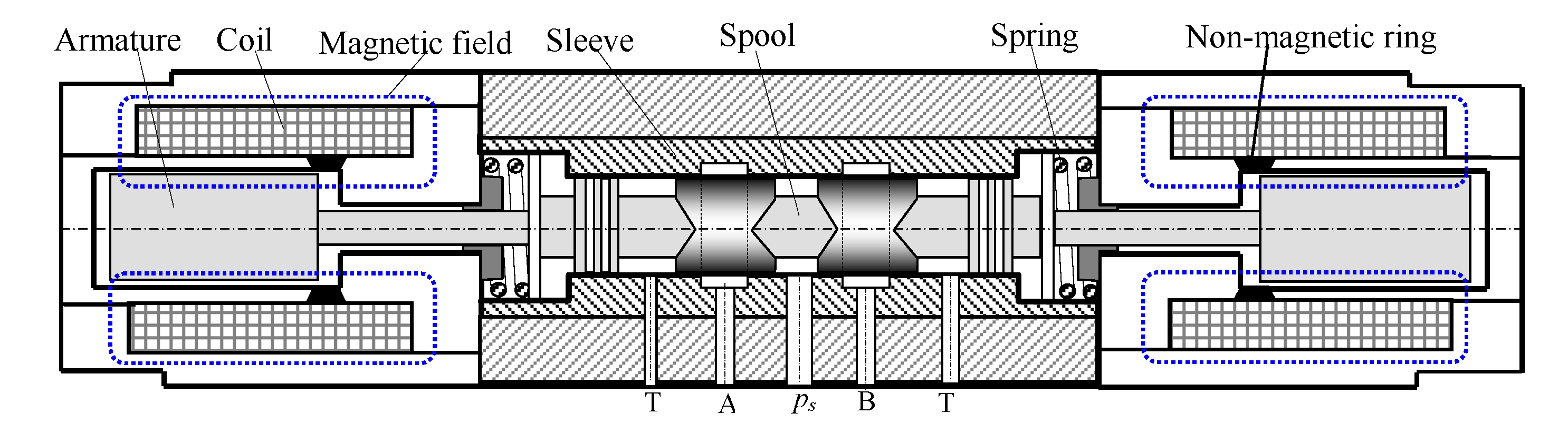
Figure 4. This valve is used in considerations regarding energy losses and their possible reduction.
The edges of the central landing (8) open and close the valve gaps between the supply port (10) and one of the cylinder chambers A and B. Lateral landings (9) open and close the gaps between the hydraulic cylinder chambers and tank. The stepping motor (1) is connected with the elastic clutch with a diameter of 10 mm (2), which is connected to the valve spool from the other side (3). This motor is used to rotate the spool (8), which at the end is connected to a ball screw thread (4). The thread is placed in a nut (5), which is attached to the stepping motor (7). The ball screw nut can rotate because it is placed in the bearing (6) assembled to the valve housing. A ball screw of diameter 8 mm and lead of 2.5 mm is used in the valve. Its preload is adjusted to 5% of the dynamic capacity, which almost completely reduces the play. In the amplifier body, three rectangular gap windows each of 2.5 mm width and 2.0 mm height have been made on both sides of the spool main piston (8); thus, the total valve gap length is equal to 6 mm, and the maximum single orifice area was 15 mm2.
The use of an elastic clutch has enabled the spool to move in an axial direction. In this design, the left motor drives the screw and the right motor drives the nut. If they are rotating in different directions, the spool velocity is equal to the sum of both drive velocities. If they are rotating in the same direction but with different velocities, very low spool movement velocities can be achieved. It is also possible to apply stepping motors with different step angles and with different micro-step modes.
In Figure 5, the photo of the built valve is shown. In this valve, two bipolar 5-phase stepping motors of type SECM569 are used. Their holding torque is 1.66 Nm (for 1 kHz), and the phase current is equal to 2.8 A. These motors were controlled by two high-power controllers. Typically, both applied stepping motors work with a full step i.e., 0.72 degrees (500 full steps per revolution). In the investigations, motors also working in a half-step (0.36 deg) or in micro-stepping mode (0.09 deg) were used. Theoretically, the maximum frequency of the stepping motors was equal to 20 kHz, but in order to assure obtaining the required output torque, the drives have worked only with the maximum frequency fmax equal to 4 kHz during the investigations. In a full-step mode, making one step by the motor has meant a 5 µm valve spool linear displacement.
In order to assure the high accuracy of the valve, the micro-stepping mode was used, in which both motors made psm = 4000 steps per one revolution, and one step of the motor resulted in spool linear displacement of only 0.625 µm.
In this paper, the authors focused directly on energy losses in the proposed valve with two stepping motors. At first, the equations describing the properties and parameters of the oil flow through the valve gaps were formulated. Then, the equations describing the power losses in the valve were given. Finally, the investigations of the energy losses during step responses were performed and discussed.

2.2. The Energy Losses in Electrohydraulic Valve

A typical control valve configuration consists of two control ports, and their flow rates are regulated with variable orifices. The expression for the turbulent fluid flow through valve orifices is:
Q = α d A ( x ) 2 ρ Δ p o
where αd—discharge coefficient (typically about 0.6), A(x) =L∙x—the area of the valve orifice, L—length of the orifice around the sleeve circumference, x—spool displacement, ρ—fluid density, and Δpo—the pressure drop on a valve orifice.
If there are no leaks, the valve is symmetrical and the double rod hydraulic cylinder is used; the fluid volumetric supply flow Q s is equal to both valve orifices flows, cylinder flow, and tank flow: i.e., Q s = Q A = Q B = Q c = Q T . The pressure drop on both orifices is also the same, i.e., Δ p A = Δ p B ; thus, the supply pressure is:
p s = Δ p A + Δ p c + Δ p B
where Δpc—the pressure drop on a hydraulic cylinder.
The hydraulic power supplied to the valve and thus to the whole drive is given by:
P s = p s Q s   [ W ] .
Assuming that the cylinder is double rod and the valve is symmetrical, the power losses on the input and output orifices are:
-
for the spool displacement direction to the right, as shown in Figure 4:
P S A = Δ p A Q A = α d 2 ρ A ( | x | ) · ( p s p A ) 3 2 ,   P B T = Δ p A Q A = α d 2 ρ A ( | x | ) · ( p B ) 3 2
-
for the spool displacement direction to the left:
P S B = α d 2 ρ A ( | x | ) · ( p s p B ) 3 2 ,   P A T = α d 2 ρ A ( | x | ) · ( p A ) 3 2
where PSA, PSB—the power losses between the supply port and port A or B, respectively, PAT, PBT—the power losses between port A or B and a tank, respectively, pA, pB—pressures on the valve output ports, and A = AA = AB—the area of the valve orifices. The useful power on a cylinder is:
P c = P A P B = Δ p c Q c = p c A c v c
where Ac—the active cylinder piston area, and vc—the piston velocity.
The power efficiency of the hydraulic valve-cylinder drive can be expressed as:
η = P c P s
For the valve described above, for parameters ρ = 780 kg/m3 and ps = 16 MPa and variable parameters spool displacement x (0.1 mm, 1 mm, 2 mm, 2.5 mm) and cylinder pressure pc (6 MPa, 4 MPa, 2 MPa, 1 MPa), the following calculated values are set in Table 1: L = 6 mm—orifice length, Q—flow, Ps—supply power, Pg, e.g., PSA + PSB or PAT + PBT—power losses on a two valve gaps, vc—piston velocity, and η—power efficiency,. The best efficiency is obtained when the flow slots of the valve are as open as possible.
If in the positive overlapped valve, gaps are closed, which means AA = AB =0, the power losses on the valve are caused only by leakages: one from the supply port to port A or B and the other from port B or A to the tank. However, in this case, the gap length is only 3 μm, and its area is very small (about i.e., 30·10−6 mm2). Such a small gap is usually quickly clogged with contamination particles.
In the valve with negative overlap, the biggest leakage flow occurs at zero spool position [25]. It is a few percent of the rated flow rate. However, if the spool displacement is small, the leakage flow is much larger than the orifice flow. In the paper [26], the nonlinear servo-valve leakage behavior is described. The flow is modeled as the turbulent flow with a flow area inversely proportional to the overlap between the spool lands and the valve orifices. The power losses on the valve are expressed as below:
P A = α d L 2 ρ ( p s p A ) 3 2   · { ( x 0 x ) ,                           x 0 x 0 2 ( x 0 k o x ) 1 ,   x < 0     P B = α d L 2 ρ ( p A ) 3 2 ·   { x 0 2 ( x 0 k o x ) 1 ,     x 0 ( x 0 x )   ,                               x < 0    
where x0—accounts for the leakage flow rate at null (x = 0), ko—determines the flow resistance of the leakage path in the overlap region as a function of spool displacement.
The parameters mentioned above i.e., x and ko, can be calculated using data given in the data sheets or according to the investigation results. The energy losses on the valve are:
E A = P A · t ,   E B = P B · t
The radial gap between the spool and the tube is essentially smaller than the spool length, causing the flow regime to be laminar. This is if the radial gap between the spool and the tube is 3 μm and the displacement of the slider is more than about 1 mm. According to the Hagen–Poiseulle equation, the leakage losses for the spool displacement direction to the right may be expressed as:
Q l A = π R ( R r ) 3 6 μ l ( p s p A ) ,   Q l B = π R ( R r ) 3 6 μ l p B
where QlA, QlB—leakages flow rate, R—orifice radius, r—insert radius, l—overlap length (1 mm), and μ—fluid viscosity (0.03 Pa·s).
The hydraulic amplifier described here has a radial symmetrical clearance of about 3 μm and symmetrical small positive overlap of 5 μm; therefore, for a supply pressure of 16 MPa, the losses caused by leakage are in a range of 0.05 dm3/min, which is very small.

3. Results

3.1. The Electrohydraulic Servo Drive Design and Its Control

In Figure 6, the basic scheme of an electrohydraulic servo drive controlled by the valve with two stepper motors is shown [29]. In the valve hydraulic amplifier, the following parameters were used: spool diameter, 10 mm; the width off the gaps, 2.5 mm. Three rectangular holes were made in the sleeve along both working edges of the slider.
In the aforementioned drive too, the same five-phase stepping motors with controllers and encoders were used along with two dedicated regulators for these stepping motors. Their input signals were the number of steps n1 and n2 to be performed by each of the stepping motors. The valve was connected to the linear hydraulic cylinder, which was moving a mass on a slider. The stepping motors’ rotor positions were measured by the encoders with resolutions of 1000 pulses/rev and 3600 pulses/rev. The cylinder piston diameter was 100 mm, the piston rod diameter was 60 mm, the stroke was 220 mm, and the shifted mass was 100 kg. The piston position was measured by an optical linear encoder (RSF) 720 mm long. The encoder output signal was given to the converter that was increasing the resolution by a factor of 5, i.e., up to a resolution of 0.5 μm. The convertor has allowed encoders to be connected to the computer-based controller.
The servo drive control algorithm was implemented on a PC-based computer on which MATLAB–Simulink software was installed. The control algorithm was implemented in the Simulink environment. The computer was connected to I/O modules from dSpace. The servo drive main controller was built basing on a typical PC in which an input/output card was installed. In order to facilitate the research process, the controller was built in the MATLAB/Simulink environment. The input signal ya given to the servo drive controller was the assumed position of the hydraulic cylinder. The current position of the hydraulic piston rod yr was measured using a linear incremental encoder. The position error was calculated as e = yayr. Then, this signal was used by two P or PI-type controllers. The maximum number of steps has been limited by software.
In the tests of the drive, the stepping motor resolution was 4000 steps per revolution. The maximum motors stepping frequency was set to 12 kHz. The measured drive maximum velocity for 4000 steps was about 105 mm/s.

3.2. Energy Losess in Electrohydraulic Valve during Drive Step Responses

The investigations described below were made using the simulation model described in [30]. This enabled broadening the research and taking the recording of the power-end energy losses. In this paper, the completely new research results concerning energy consumption by the drive during step responses are presented. In the first tests, one stepping motor was used, which was controlled by a P-type regulator. Its proportional gain coefficient kP was set to 500. The drive was supplied with a constant pressure of 16 MPa. The investigation results, i.e., step responses for assumed distances of 5 mm, 10 mm, and 20 mm for both directions are shown in Figure 7a. The behavior of a servo drive with two stepper motors working with two P-type regulators was also investigated. The proportional gain coefficients were kP1 = 350 and kP2 = 230. The step responses of the drive are shown in Figure 7b. In this case, both the rise time and the settling time were significantly shorter, while the overshot was smaller. For an assumed signal of 20 mm, the settling time for a valve with one motor was reached after approximately 1.2 s, while for the valve with two motors, it was 0.7 s.
Figure 8 shows the recorded power, energy losses, and Integral of Absolute Error (IAE) changes of the signals on the control valve. It is clearly visible that the power losses are directly related with the overshot. For a valve with one stepping motor, the max power loss was 14 kW, and the total energy loss was 6.8 kW∙s. The application of two stepping motors reduces the overshot, settling time, and the total energy consumption to 5.5 kW∙s. It is also visible that the energy consumption curves E(t) and IAE(t) in time have almost the same shape and can be interchangeably used to compare the energy consumption of different solutions.
The curves recorded have shown that when working with the P-type controller, the overshot value is big and significantly increases in the increase in the set position value. Therefore, in order to reduce the overshot, a special algorithm was proposed [31]. The step responses of the servo drive with one (Figure 9a) or two (Figure 9b) stepping motors, controlled by this algorithm, are presented below. It can be seen that the overshoot has been almost completely eliminated in this case.
In Figure 10, the same signals as presented in Figure 8 are shown. While the maximum instantaneous power loss is essentially the same as in the case discussed above, the power losses are significantly lower when the overshot-free algorithm is used. The total energy loss for the valve with one stepping motor was about 0.25 kW∙s, and for the valve with two stepping motors, it was 1.3 kW∙s, which is respectively much less in comparison to 6.8 kW∙s and 5.5 kW∙s.
In Figure 11a, the step responses of the electrohydraulic servo drive with the valve controlled by one stepping motor and by a P-type regulator without and with an overshot-free algorithm are compiled. The gain coefficient was set to 400. In this figure, also, the step responses (black curves) obtained in investigations of the real servo drive are added. It is visible that the step response curves obtained from the simulation are in very good agreement with the curves recorded in the laboratory. This allows concluding that the energy and power losses recorded in the simulation correspond well to the reality. Figure 11b shows the curves of energy loss changes over time, which were recorded during step responses. They correspond to the waveforms of step responses shown in Figure 11a. The application of an overshot-free algorithm allowed for a significant reduction of energy losses from 5.5 to 2.6 kWs for a displacement of 20 mm and from 2.2 to 1.2 kWs for a displacement of 10 mm.
Figure 12a,b presents similar investigations results but when two stepping motors are used in the valve. In this case, the application of an overshot-free algorithm allowed a similar reduction of energy losses as when a single stepping motor was used. In addition, the step responses (black curves) obtained in investigations of a real servo drive are added. In addition, these waveforms correspond well to real ones.

4. Discussion

The article deals with the problem of the influence of the chosen parameters used in an electrohydraulic drive for energy losses reduction occurring in electrohydraulic valves driven by stepping motors. At first, the paper describes different types of electrohydraulic valves in which one or two stepping motors are applied. The designed and built valve with two stepping motors is considered in more detail. This valve enables obtaining both low and relatively high valve spool velocity and respectively low and high gain coefficients. The equations describing these losses are given, which allows determining the losses of power, energy, and the efficiency for various parameters of the valve operation. Using the given equations, the parameters of the drive for different spool displacements and piston pressures were determined and are summarized in the table. The results showed that the smallest losses occur when the valve is fully open. In the paper, the instantaneous losses of power and energy occurring during step responses over various distances, using one or two stepping motors, are recorded. The electrohydraulic servo drive with the valve with two stepping motors is built and investigated. The influences of using one or two stepping motors in a valve on energy losses are investigated. The power losses on the valve are recorded for an ordinary P-type controller and the same P-controller but with a specially developed overshot-free algorithm. The curves of energy losses on the valve during the step response have shown that the use of two stepping motors improves the dynamics of the valves and the entire drive, and it slightly reduces the aforementioned losses. However, the most significant reduction in energy losses during step responses has been achieved through using an algorithm that has eliminated the overshoot. This reduction was around 50%, which is a big saving, especially when the drive makes frequent starts and stops. Servo drives with investigated valves can be used for example in precise cold metal forming.

5. Conclusions

The following conclusions can be drawn from the research:
  • The equations proposed in this paper can be used in simulation models to determine and record the valve energy consumption over time.
  • Considerable throttling losses on a valve during step responses are observed if the overshot in the output signal is presented; thus, the overshot-free algorithm slightly reduced the energy losses, i.e., by about 50%.
  • The results obtained for the valve with the stepper motors described in the article may also be useful for all other electrohydraulic as well as electropneumatic and electric servo drives. They indicate energy losses occurring on elements such as valves or transistors while supplying energy to the motor and can help in servo drive optimization.

Author Contributions

Conceptualization, J.O. and A.M.; methodology, A.M.; software, J.O.; validation, J.O.; formal analysis, A.M.; investigation, J.O.; resources, J.O. and A.M.; data curation, J.O.; writing—original draft preparation, A.M.; writing—review and editing, A.M.; visualization, J.O.; supervision, A.M.; project administration J.O.; funding acquisition, A.M. Both authors have read and agreed to the published version of the manuscript.

Funding

By Polish Ministry of Science and Education grant no. 0614/SBAD/1547.

Institutional Review Board Statement

Not applicable.

Informed Consent Statement

Not applicable.

Data Availability Statement

Not applicable.

Conflicts of Interest

The authors declare no conflict of interest.

References

  1. Jelali, M.; Kroll, A. Hydraulic Servo Systems, Modelling, Identification and Control; Springer: Berlin/Heidelberg, Germany, 2003. [Google Scholar]
  2. Murrenhoff, H. Hydraulic Drives in Stationary Applications. In Customer Benefits of Fluid Power; Internationales Fluidtechnisches Kolloquium: Düren, Germany, 2006; pp. 11–36. ISBN 3832248404. [Google Scholar]
  3. Manring, N.D.; Fales, R.C. Hydraulic Control Systems; John Wiley & Sons, Inc.: Hoboken, NJ, USA, 2020. [Google Scholar]
  4. Beck, D.B.; Fischer, D.E.; Kolks, D.G.; Lübbert, D.J.; Michel, D.S.; Schneider, D.M. Novel System Architectures by Individual Drives. In Proceedings of the 10th International Fluid Power Conference, Dresden, Germany, 8–10 March 2016; pp. 29–62. [Google Scholar]
  5. Fassbender, S.Q.; Vacca, D.A.; Busquets, E. A high-efficient solution for electro-hydraulic actuators with energy regeneration capability. Energy 2021, 216, 119291. [Google Scholar]
  6. Gradl, C.; Scheidl, R. Performance of an Energy Efficient Low Power Stepper Converter. Energies 2017, 10, 445. [Google Scholar] [CrossRef] [Green Version]
  7. Murrenhoff, H. Innovationen in der Fluidtechnik. I Internationales Fluidtechnisches Kolloquium in Aachen, Beiträge zu den Themenschwerpunkten, Gruppe 1: Innovationen in der Fluidtechnik, Gruppe 2: Antriebstechnik im Wettbewerb; Mainz: Aachen, Germany, 1998. [Google Scholar]
  8. Murrenhoff, H. Servohydraulik; Verlag Meinz: Aachen, Germany, 1998. [Google Scholar]
  9. Norvelle, F.D. Electrohydraulic Control Systems; Prentice Hall: Hoboken, NJ, USA, 2000. [Google Scholar]
  10. Feuser, A. Modern Electrohydraulic Drive Technology for Stationary Machinery in Industrial Automation. In Proceedings of the 7th International Fluid Power Conference, Gruppe 4/Group 4 Stationärhydraulik/Industrial hydraulics, Aachen, Germany, 24 March 2010. [Google Scholar]
  11. Murrenhoff, H. Trends in Valve Development. Olhydraul. Pneum. 2003, 46, 1–36. [Google Scholar]
  12. Ruggieri, M.; Gardenghi, S. Benefit of the Asymmetrical Half Bridge on Proportional Valve Electronic Control. In Proceedings of the 7th International Fluid Power Conference, Gruppe H/Group HValves/Ventile, Aachen, Germany, 22–24 March 2010. [Google Scholar]
  13. Rydberg, K.E. Energy Efficient Hydraulics—System Solutions for Minimizing Losses. In Proceedings of the National Conference on Fluid Power, “Hydraulikdagar’15”, Linköping, Sweden, 16 March 2015. [Google Scholar]
  14. Huova, M.; Linjama, M.; Huhtala, K. Energy Efficiency of Digital Hydraulic Valve Control Systems; SAE Technical Paper, 2013; Available online: https://doi.org/10.4271/2013-01-2347 (accessed on 20 September 2021).
  15. Karvonen, M.; Heikkilä, M.; Tikkanen, S.; Linjama, M.; Huhtala, K. Aspects of the Energy Consumption of a Digital Hydraulic Power Management System Supplying a Digital and Proportional Valve Controlled Multi Actuator System. In Proceedings of the ASME/BATH 2014 Symposium on Fluid Power & Motion Control FPMC2014, Bath, UK, 10–12 September 2014. [Google Scholar] [CrossRef]
  16. Finzel, R.; Helduser, S.; Jang, D.S. Electro-Hydraulic Dual Circuit System to Improve the Energy Efficiency of Mobile Machines. In Proceedings of the 7th International Fluid Power Conference, Aachen, Germany, 22–24 March 2010. [Google Scholar]
  17. Liu, S.; Yao, B. Energy-Saving Control of Single-Rod Hydraulic Cylinders with Programmable Valves and Improved Working Mode Selection. SAE Trans. 2002, 1, 51–61. [Google Scholar] [CrossRef] [Green Version]
  18. Sędziak, D. Basic Investigations of Electrohydraulic Servovalve with piezo-bender element. Arch. Mech. Technol. Mater. 2006, 26, 185–190. [Google Scholar]
  19. Rybarczyk, D.; Owczarek, P.; Sędziak, D.; Owczarkowski, A. Modelling of electrohydraulic drive with a valve controlled by synchronous motor. Prog. Automat. Robot. Measur. Tech. Adv. Intellig. Syst. Comput. 2015, 350, 215–222. [Google Scholar]
  20. Milecki, A.; Rybarczyk, D. Modelling of an electrohydraulic proportional valve with a synchronous motor. J. Mech. Eng. 2015, 61, 517–522. [Google Scholar] [CrossRef]
  21. Pfeifer, T.; Schmitt, R. Autonome Produktionszellen. Komplexe Produktionsprozesse Flexibel Automatisieren (VDI-Buch); Springer: Berlin/Heidelberg, Germany, 2015; ISBN 978-3540292142. [Google Scholar]
  22. Branz, H. Hydraulische Antriebe und Steuerungen für Werkzeugmaschine. Olhydraul. Pneum. 2001, 45, 596–601. [Google Scholar]
  23. Available online: voith.com/corp-en/hydraulics-pneumatics-cooling/hydraulic-systems-components/valve-technology.html?129073%5B%5D=4 (accessed on 20 September 2021).
  24. Becker, M. Schrittmotor als Aktuator für Hydraulik-Wegventile. Olhydraul. Pneum. 2000, 44, 249–253. [Google Scholar]
  25. Hampejs, K. Hydraulic Linear Servo Amplifier. Patent No. EP0296104A1, 1988. European Patent Office. Available online: https://patents.google.com/patent/EP0296104A1/en (accessed on 20 September 2021).
  26. Zingsem, W. Hydraulik in der Vorschubtechnik. Olhydraul. Pneum. 1994, 38, 529–530. [Google Scholar]
  27. Milecki, A. Elektrohydraulischer Servoantrieb mit Schrittmotor und Elektrischer Rückführung. Olhydraul. Pneum. 1999, 6, 450–452. [Google Scholar]
  28. Milecki, A.; Myszkowski, A. Modelling of electrohydraulic servo drive used in very low velocity applications. Int. J. Model. Identif. Control. 2009, 7, 246. [Google Scholar] [CrossRef]
  29. Milecki, A.; Ortmann, J. Electrohydraulic Valve with Two Stepping Motors. In Proceedings of the International Conference Challenges in Automation, Robotics and Measurement Techniques (Automation), Warsaw, Poland, 2–4 March 2016; pp. 73–79. [Google Scholar]
  30. Milecki, A.; Ortmann, J. Control of electrohydraulic drive with valve having two stepping motors. In Proceedings of the 2016 17th International Carpathian Control Conference (ICCC), High Tatras, Slovakia, 9 May–1 June 2016; pp. 494–498. [Google Scholar] [CrossRef]
  31. Milecki, A.; Ortmann, J. Electrohydraulic linear actuator with two stepping motors controlled by overshoot-free algorithm. Mech. Syst. Signal Process. 2017, 96, 45–57. [Google Scholar] [CrossRef]
Figure 1. Proportional directional valve.
Energies 14 06114 g001
Figure 2. The valve with one stepping motor (the gaps are marked with yellow color) [28].
Energies 14 06114 g002
Figure 3. Three-land spool with rectangular gaps in a sleeve applied in a four-way hydraulic valve. (a) On the right side. (b) In the middle position (closed). (c) On the left side.
Energies 14 06114 g003
Figure 4. Drawing of the valve with two stepping motors (the gaps are marked with yellow color) [29,30].
Energies 14 06114 g004
Figure 5. The photos of the valve and the electrohydraulic drive on the test stand.
Energies 14 06114 g005
Figure 6. The scheme of electrohydraulic servo drive controlled by a valve with two stepping motors [29,30].
Energies 14 06114 g006
Figure 7. The servo drive with P-type controller step responses controlled by: (a) One stepping motor. (b) Two stepping motors.
Energies 14 06114 g007
Figure 8. The power losses on a valve (P), energy losses (E), and IAE of servo drive step responses. (a) Assumed distance 20 mm, one stepping motor kP = 500. (b) Distance 20 mm, two stepping motors kP1 = 300, kP2 = 230. (c) Distance 10 mm, one stepping motor kP = 500. (d) One stepping motor. (b) Two stepping motors P-type controller with gain coefficients: kP1 = 300, kP2 = 230.
Energies 14 06114 g008
Figure 9. The servo drive controlled using an overshoot-free algorithm step response. (a) With one stepping motor. (b) With two stepping motors.
Energies 14 06114 g009
Figure 10. The valve power (P) and energy losses (E) and IAE curves recorded during step responses controlled by an overshot-free algorithm servo drive. (a) Assumed distance 20 mm. (b) Assumed distance 10 mm.
Energies 14 06114 g010
Figure 11. Comparison of P-type regulator and P-type with overshot-free algorithm. (a) Step responses of the servo drive with one stepping motor. (b) Energy losses on a valve.
Energies 14 06114 g011
Figure 12. The servo drive with two stepping motors and its model step (color curves: brown and blue) responses. (a) With P-type controller. (b) With P-type and overshot-free algorithm.
Energies 14 06114 g012
Table 1. Parameters of the drive for different spool displacements and piston pressures.
Input ParametersCalculated Parameters
x [mm] pc [MPa]Q [dm3/s]Ps [W]Pg [W]Pc [W]vc [mm/s]η
0.1 10 0.0467292731827.60.25
1.0 120.372595214882976620.50
2.0 140.526841710526313880.75
2.5 150.46574404656510780.875
Publisher’s Note: MDPI stays neutral with regard to jurisdictional claims in published maps and institutional affiliations.

