Article

Study of Operation of the Thermoelectric Generators Dedicated to Wood-Fired Stoves

AGH University of Science and Technology, Faculty of Energy and Fuels, Department of Sustainable Energy Development, Mickiewicza Ave. 30, 30-059 Krakow, Poland
Energies 2021, 14(19), 6264; https://doi.org/10.3390/en14196264
Submission received: 2 September 2021 / Revised: 27 September 2021 / Accepted: 28 September 2021 / Published: 1 October 2021
(This article belongs to the Special Issue Sustainable Combustion Systems and Their Impact II)

Abstract

:
Thermoelectric generators are devices that harvest waste heat and convert it into useful power. They are considered as an additional power source in the domestic sector, but they can also be installed in off-grid objects. In addition, they are a promising solution for regions where there is a lack of electricity. Since biomass heating and cooking stoves are widely used, it is very appropriate to integrate thermoelectric generators with wood-fired stoves. This paper shows the experimental analysis of a micro-cogeneration system equipped with a wood-fired stove and two prototypical constructions of thermoelectric generators dedicated to mounting on the flue gas channel. The first version was equipped with one basic thermoelectric module and used to test various cooling methods, while the second construction integrated four basic thermoelectric modules and a water-cooling system. During the tests conducted, the electricity generated in the thermoelectric generators was measured by the electronic load, which allowed the simulation of various operating conditions. The results obtained confirm the possibility of using thermoelectric generators to generate power from waste heat resulting from the wood-fired stove. The maximum power obtained during the discussed combustion process was 15.4 W (if this value occurred during the entire main phase, the energy generated would be at a level of approximately 30 Wh), while the heat transferred to the water was ca. 750 Wh. Furthermore, two specially introduced factors (CPC and CPTC) allowed the comparison of developed generators, and the conclusion was drawn that both developed constructions were characterized by higher CPC values compared to available units in the market. By introducing thermoelectric modules characterized by higher performance, a higher amount of electricity generated may be provided, and sufficient levels of current and voltage may be achieved.

1. Introduction

The use of wood-fired stoves (WFS) is common in European countries and Northern America, providing CO2-neutral energy for residential heating [1]. WFSs are devices dedicated to heating purposes that provide low-cost heating and an aesthetic atmosphere from burning wood. Additional benefits can be obtained by introducing a microscale power generation system (mCHP) based on thermoelectric generators (TEGs). Micro-cogeneration is a promising solution because it allows one to increase the energy and economic efficiency of stove operation and contributes to reducing carbon dioxide emissions in countries where electricity production is mainly based on fossil fuels [2]. Thermoelectric devices are silent and do not generate vibrations since their operation does not require the contribution of mechanical energy [3]. Many thermoelectric materials are currently explored for power generation applications, such as GeTe [4], PbTe [5], half-Heusler [6], and skutterudites [7]. Unfortunately, the thermoelectric generators currently available on the market are not properly designed to cooperate with existing and developing wood-fired stoves. Therefore, it is crucial to develop a new construction of TEG. Among other options, a thermoelectric generator may be located in the flue gas channel; thus, the generator design can be universal for various WFS constructions.
In order to generate electricity from a thermoelectric module, the temperature difference between its hot and cold surfaces is necessary. Therefore, thermoelectric generators dedicated to utilization with wood-fired stoves typically consist of three key elements:
  • Heat exchanger, which absorbs the heat generated in the stove (directly from the furnace or from the chimney) and transfers it into the thermoelectric modules;
  • Thermoelectric modules (TEMs), which generate electricity when a temperature difference exists between their ends;
  • Heat sink dedicated to dissipating the heat from the thermoelectric modules.
The principle of thermoelectric generation is shown in Figure 1.
The TEGs’ operation is determined by the temperature difference between the two sides of the generator. The hot electrons travel more quickly towards the cold side than the cold electrons moving towards the hot side. Consequently, the cold end of the TEG becomes negatively charged, and the hot end is positively charged. The operation of TEG is characterized by a relatively low conversion efficiency (~5%), but such a low value is not crucial because TEG is typically used for the recovery of waste heat [8,9]. The main advantages of using thermoelectric generators are as follows: no additional energy is required from the stove; almost no maintenance is required since thermoelectric generators do not include moving parts; and thermoelectric generators do not require a large battery system and work continuously in any weather conditions [10]. Generally, TEGs can be considered as additional power sources in the domestic sector, but they can also be installed in off-grid objects (such as winter houses). Moreover, they are a promising solution for regions where there is still a lack of electricity or for regions in which providing electricity to cover the basic needs of the population is very expensive due to using traditional power plants (today, more than 20% of the world’s population in developing countries is still living without electricity [11]).
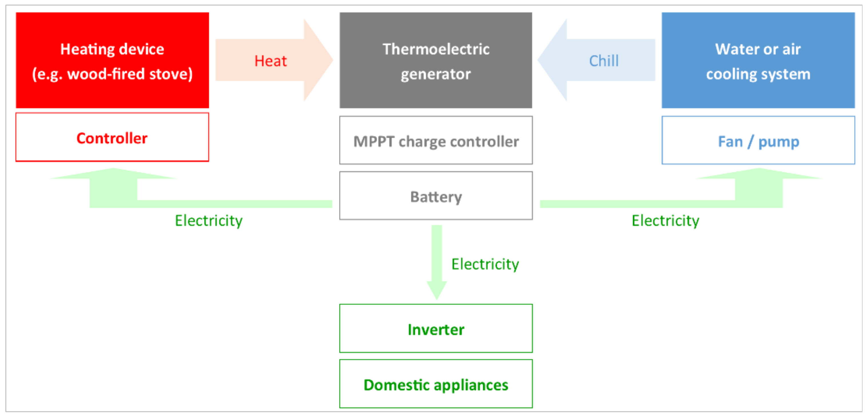
The possibility of a the practical implementation of the TEG in a wood-fired stove is shown in Figure 2. The proposed system consists of a thermoelectric generator, a voltage converter (supplying voltage at a level of 12/24 V DC at its output), a battery charge controller, a battery, and a controller (combustion optimizer).
The power generated in TEG is consumed by the controller, air throttle servomotor, and cooling system. Proper control of the combustion process allows clean wood combustion, which is essential from the point of view of Eco-Design requirements [12]. On the other hand, surplus power may be used to power the circulation pump in the central heating or hot water systems and to power different home appliances (by using an inverter) [13].
There are some works in the literature that present applications of thermoelectric modules to wood-fired stoves, including heating, cooking, and multifunctional devices. Commercially available thermoelectric modules made of bismuth-telluride-based materials have been analyzed by Lertsatitthanakorn. The electrical performance of the modules installed on a cooking stove was 2.4 We at a temperature difference of approximately 150 K. This power was enough to run a small radio or a low-power incandescent light bulb [9]. Another example of the integration of TEG generator with the cooking stove was shown in [14]. In this paper, Mal et al. used the thermoelectric generator to run the small DC-fan installed on a chimney (also other functions such as lighting and battery charging were considered). Two novel electrical circuit topologies with a TEG were presented for efficient power generation and clean cooking. Champier et al. studied a micro-cogeneration system with a TEG heated by a multifunction stove. The performance of a tested thermoelectric generator was 9.5 We, whereas the maximum power of stable electricity available to end users was around 7.6 We [15]. Mastbergen and Wilson presented a prototype of a thermoelectric generator cooled by a 1 We fan. The prototype developed generated a net power of 4 We that was used to light an array of high-intensity LEDs [16]. Patowary and Baruah tested the feasibility of integrating a TEG module with a clay-made cooking stove. Preliminary tests of the TEG-integrated cookstove showed a potential of generating 2.7 We of electrical power and illuminating a 3 We LED bulb [17]. In [18], a compact water-cooled thermoelectric generator based on a portable gas stove was designed and analyzed. The TEG incorporates a newly designed heat collector, eight TE modules, and a radiator in order to ensure its sufficiency of electric power (approximately 12.9 We). Montecucco et al. showed a system developed to charge a lead-acid battery and simultaneously transferred heat to water for heating. This system produced an average of 600 Wt (thermal energy) and 27 We (electrical energy) during a 2 h experiment in which the TEG efficiency was around 5% [19]. Other tests performed by Liu et al. showed that a power generator, comprising of 96 TEG modules, had an installed power of 500 We at a temperature difference of ca. 200 K and an output power of ca. 160 We at a temperature difference of 80 K [20]. O’Shaughnessy et al. performed an 80 day field test on a cooking stove equipped with air-cooled TEG (fan with an electrical power of 0.5 We). Such a developed thermoelectric generator provided 3 Wh a day during the conducted investigations [21]. Two other examples were presented by Favarel et al. [22] and Goudarzi et al. [23]. Favarel et al. developed the mCHP system with eight thermoelectric modules estimated to produce electrical power at a level of ca. 28 We, while Goudarzi et al. integrated 21 TE modules estimated to generate maximum power at a level of ca. 351 We. The summarization of previously selected research on TEGs integrated with stoves is shown in Table 1.
Among domestic applications, there is the possibility of recovering waste heat using thermoelectric generators in the industrial sector. For example, Araiz et al. carried out a study on the thermoelectric recovery of hot gases from a stone wool manufacturing plant and reported a maximum net power production of 45 kWe [24]. Further applications of TEGs, including waste heat recovery from industry and homes as well as waste heat recovery from transport systems, were discussed in [3]. In addition to thermoelectric generators, biomass-fired cogeneration systems can operate, e.g., according to the Organic Rankine Cycle [25] or the Rankine Cycle/modified Rankine Cycle [26,27].
By analyzing literature sources and taking into account previous investigations, it may be concluded that most of the performed works were based on cooking stoves and multifunction stoves (i.e., stoves integrate cooking and hot water heating functionalities). On the other hand, wood-fired heating steel stoves are commonly used for heating purposes. Such stoves may direct heat in one room (in which the stove is installed) or heat many rooms by using air as a heating medium (if a hot air distributing system is used). Moreover, they may cooperate with central heating systems or hot water systems (water is heating in a water jacket or a flue gas–water heat exchanger). Due to their construction and operational parameters, heating stoves are promising heat sources for thermoelectric generators. However, although it seems to be a relatively simple task, problems with the proper selection of thermoelectric generators do arise. Here, the ideal operating and maximum hot side temperatures, as well as the required cold side temperature, are the most significant factors. Proper mounting, allowing good contact and sufficiently high heat flux, is also essential. The thermoelectric generators currently available on the market are not properly designed to cooperate with existing wood-fired stoves. The example of using market-available TEGs with a typical wood-fired stove was shown in [28]. Three types of thermoelectric generators were considered:
  • TEG No. 1—air-cooled unit with a matched power of 45 We (designed for mounting on a flat hot surface);
  • TEG No. 2—water-cooled unit with a matched power of 100 We (designed for mounting on a flat hot surface);
  • TEG No. 3—water-cooled unit with a matched power of 350 We (designed for mounting on a flue gas channel).
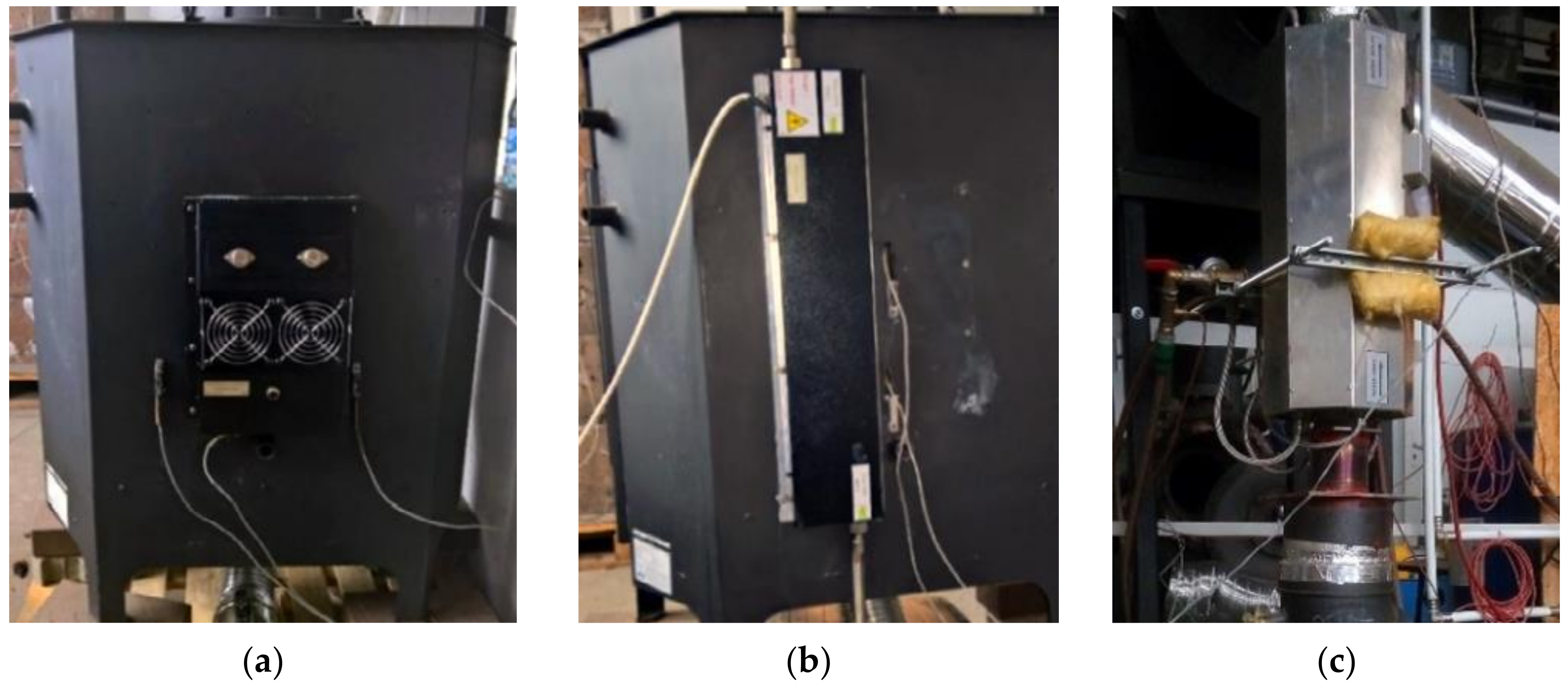
The illustration of the tested wood-fired stove with incorporated thermoelectric generators is shown in Figure 3.
The tests of three thermoelectric generators presented in [28] exhibited crucial parameters from the standpoint of the developed micro-CHP system: the size of the hot sides, the surface smoothness, the required heat flux, and sufficient temperature values. As demonstrated, it was possible to reach a power corresponding to 7.2% ± 1% of the nominal power for TEG No. 3 (25.1 We), 31.2% ± 2% for TEG No. 2 (31.2 We), and 41.7% ± 3% for TEG No. 1 (18.8 We). Really poor performance of the TEG No. 3 was caused by a flue gas channel that was too narrow, which disturbed the combustion process (dimming the fire and making the flue gas flow and, consequently, heat flux to the hot side of TEG No. 3, which is significantly lower than demanded). It was caused by the fact that this model of TEG was originally developed for installation in automobiles. On the other hand, the implementation of TEG No. 3 was quite easy and did not affect stove construction. Moreover, the construction of such a generator allows direct contact between its hot side and flue gas, without an additional steel layer (rear wall of the stove, as in the case of TEG No. 1 and TEG No. 2). Thus, despite the low performance of the market-available TEG No. 3, the decision was made to develop a construction of a thermoelectric generator that is dedicated to montage on a flue gas channel and to operate with heating devices.

2. Materials and Methods

2.1. Configuration of the Experimental Rig

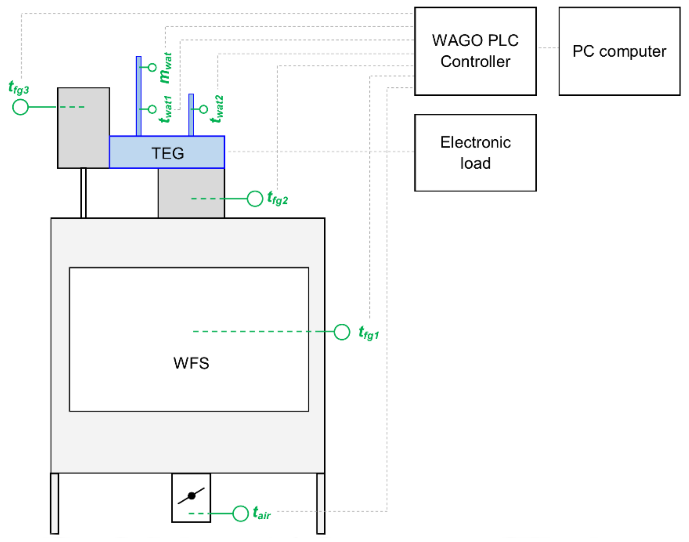
The experiments were carried out by using a test rig equipped with a wood-fired steel stove, dedicated constructions of the thermoelectric generator, and dedicated control and measurement systems. The general scheme of the experimental rig is shown in Figure 4.
The main parameters of the experimental rig and their short description are as follows:
  • The wood-fired steel stove possessed efficiency at a level of 81% and nominal heating capacity at a level of 12 kWt (during typical operation, this power ranges from 8 to 16 kWt). In the presented investigations, pinewood with a moisture content of 12–13% and a lower heating value (LHV) of approximately 4.4 kWh/kg was burned. The initial fuel input ranged from 4.0 to 6.0 kg depending on the measurement series. Then, additional wood inputs were added during the combustion process. The view of the tested wood-fired stove is shown in Figure 5.
  • Dedicated constructions of the thermoelectric generator provided for installation on the chimney were used (two versions were analyzed: The first one was equipped with one Bi2Te3 TEM characterized by a matched power of 10.5 We and operated with a temperature difference of 150 K. The second one had four low-cost Bi2Te3 TEMs characterized by a total matched power of 28.8 We and operated with a temperature difference of 250 K).
  • Dedicated control and measurement systems equipped with the following:
    WAGO PLC controller with a set of I/O modules, including analog inputs and outputs (4–20 mA, 0–10 V, Pt100, PTTK) and digital inputs and outputs (0/24 V);
    Thermocouple and resistance sensors provided for monitoring the temperature of flue gas inside the combustion chamber (tfg1), flue gas in the flue gas channel (at the inlet of the thermoelectric generator—tfg2; and the outlet from the thermoelectric generator—tfg3), air flown to the combustion chamber (tair), and cooling water temperature (at the inlet of the thermoelectric generator—twat1; and the outlet from the thermoelectric generator—twat2);
    Thermo-anemometer provided to measure the speed of air blowing into the combustion chamber with a measurement range of 0–2 m/s;
    Throttle with servomechanism controlled via analog 0–10 V signal to control the amount of air flowing to the combustion chamber;
    Water flowmeter to measure cooling water flow (mwat);
    PC with installed CoDeSys software.
Measurements were recorded using a modular control and measurement system with a PLC controller in a 1 s time interval. The PLC controller was also used to set the position of the air throttle (from 0 to 100%). At the current stage, the control of air throttle opening was realized based on the current hot surface temperature. The degree of opening of the air throttle was constant over time in the initial phase of the combustion process when the temperatures of the flue gas of the temperature and hot surface temperature were rising. When the temperature of the hot side exceeded the assumed level (lower than the operating temperature of the TEG), the air throttle was slowly closed by the control algorithm. After the hot side temperature reached the target level (corresponding to the TEG operating temperature), the opening degree of the air throttle continuously changed depending on the measured temperature.
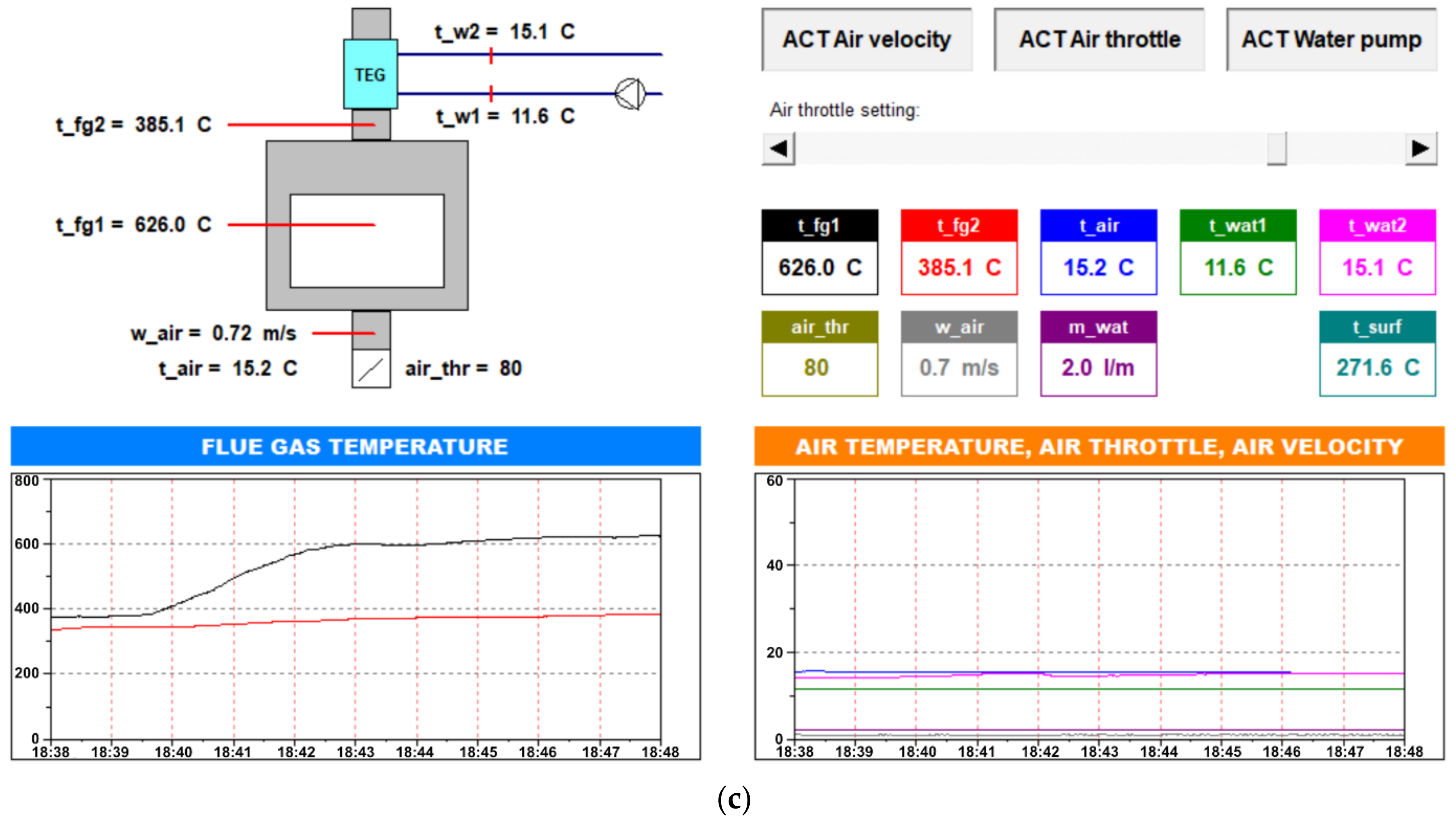
Views of the control cabinet, electronic load, and visualization created in the CoDeSys software are shown in Figure 6.

2.2. The Initial Version of the Developed Thermoelectric Generator (TEG No. 4)

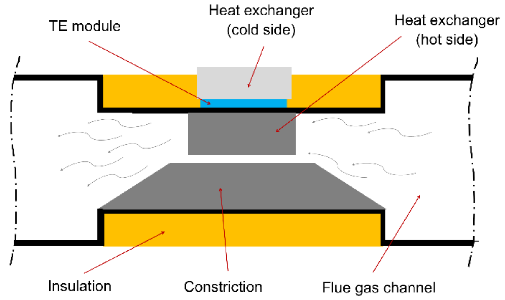
The initial version of the thermoelectric generator was equipped with one Bi2Te3 thermoelectric module installed on the steel plate. The TE module was designed to a maximum differential temperature of 150 K. Inside the generator, a steel constriction and radiator were installed (to increase the flow of flue gas in the boundary layer and to intensify heat exchange between flue gas and the hot side of the TE module). The TEG was insulated by a 50 mm layer of mineral wool. The simplified scheme of the initial version of the developed thermoelectric generator (TEG No. 4) is shown in Figure 7.
The thermoelectric generator (TEG No. 4) was installed on the stove’s chimney. Three types of cooling systems were introduced and tested: heat pipe heat sink based on natural convection, heat pipe heat sink with air fan, and water heat exchanger.

2.3. The Prototype of the Developed Thermoelectric Generator (TEG No. 5)

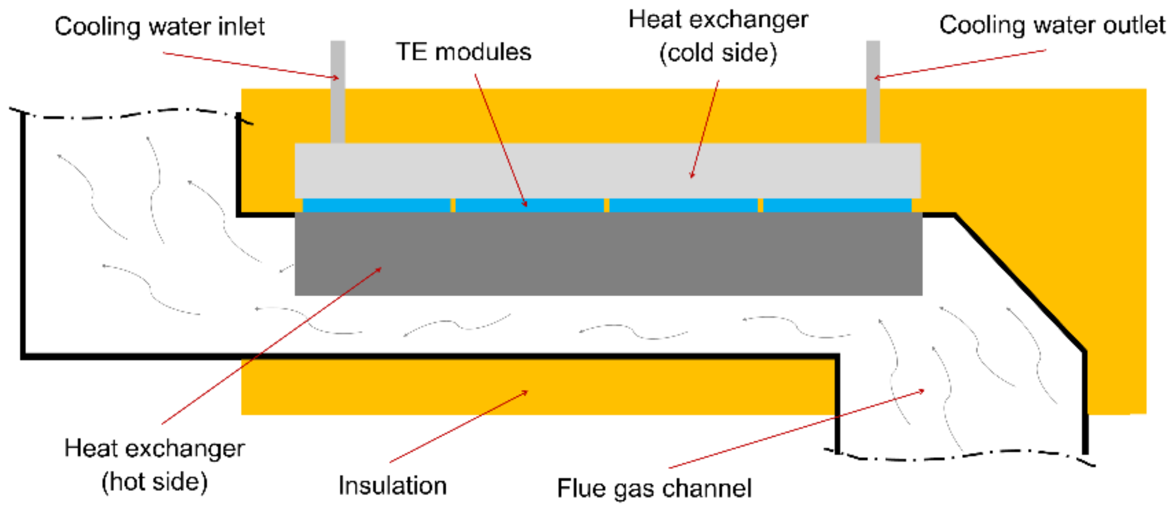
The prototype construction of the thermoelectric generator (TEG No. 5) was improved by taking into account the results obtained during tests performed using TEG No. 4. The hot side of the TEG was realized in the form of a rectangular channel with a radiator. The radiator consisted of elements arranged in parallel to the direction of the flow of the flue gas. In this manner, the surface of heat transfer from the gases to the exchanger increased significantly. Moreover, the positive effect of changing the direction of the flue gas flow was used to ensure high temperature in the area of the hot side. Four thermoelectric modules were mounted directly on the top radiator surface. These modules were designed to a maximum differential temperature of 250 K. Additionally, to eliminate the excessive cooling of the exchanger surface caused by ambient air, thermal insulation was applied, which consists of a 5 cm thick layer of mineral wool. The simplified scheme of the prototype of the thermoelectric generator developed (TEG No. 5) is shown in Figure 8, while its working construction is presented in Figure 9.
In the case of TEG No. 5, only a water-cooling system was implemented (due to the higher heat capacity of water compared to air, water cooling is generally more efficient than air cooling). Due to the higher maximum differential temperature of TE modules (250 K compared to 150 K), the control algorithm was modified to provide a higher flue gas temperature. However, increasing the operational temperature had a positive effect on the amount of electricity generated in the TEG.

2.4. Comparative Power Coefficient and Comparative Power-to-Temperature Coefficient

In order compare each of the series, a comparative power coefficient (CPC) and comparative power to temperature coefficient (CPTC) were introduced. The formulas are provided below:
C P C = P M P P , e x p P M P P , t h e o r ,
where
PMPP,exp—matched power obtained during tests, W;
PMPP,theor—matched power given by manufacturer, W;
C P T C = P M P P , e x p T f g ,   W / K
where
PMPP,exp—matched power obtained during tests, W;
Tfg—flue gas temperature in time, when matched power was observed, K.

2.5. Economic Analysis of the Operation of mCHP System

The economic model used to assess the performance of the developed mCHP system was based on two types of cost: investment costs (estimated by using market data and the experience of the authors) and fuel costs (based on the analysis of dozens of offers available online). By taking these costs into account, the economic indicators in the form of simple payback time (SPBT) and net present value (NPV) were determined.
The simple payback time of the installation was calculated as a function of the initial cost energy cost, and wood cost was calculated based on the following equation:
S P B T = I 0 E S F C ,   years
where
I0—investment costs, EUR per year;
ES—energy savings, EUR per year;
FC—fuel costs, EUR per year.
The net present value (NPV) after 10 years was calculated by using previously listed values and a discount rate of 5%. The following equation was used:
N P V = t = 1 n E S F C 1 + i t I 0 ,
where
i—discount rate;
t—number of periods.

3. Results

The operational parameters of the developed thermoelectric generators (TEG No. 4 and TEG No. 5)—i.e., voltage, current, and generated power—varied along with the variations in the temperature of their hot and cold sides. This effect was analyzed, and the performance of the developed thermoelectric generators was determined.

3.1. Results of the Tests of the Operation Parameters of TEG No. 4

3.1.1. Variations in the Temperature of the Flue Gas, Hot Surface, and Cooling Water

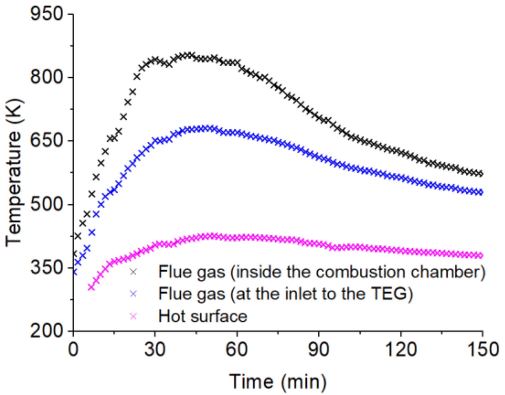
The first part of the performed tests was devoted to determining the temperature variations inside the combustion chamber and in the flue gas channel (at the inlet to TEG No. 4), as well as the temperature variations of the hot surface (a place dedicated to montage the TE module). The initial fuel input consisted of 6.0 kg of pinewood. As shown in Figure 10, the temperature measured in the flue gas channel was lower by an average of 110 K compared to the temperature inside the combustion chamber, while the surface temperature was lower by an average of 210 K compared to the temperature measured in the flue gas channel. The maximum measured temperature of the surface dedicated to the montage TE module was 426.2 K (that is, 143.2 °C), while its average value was 394.7 K (that is, 111.7 °C). It may be underlined that surface temperature was characterized by stability over time, but the air throttle opening was constant over time, and no additional fuel inputs were realized.

3.1.2. Variations in the Temperature of the Flue Gas, Hot Surface, and Cooling Water

In the second step, three cooling systems were introduced to TEG No. 4 and compared: heat pipe heat sink based on natural convection, heat pipe heat sink with an air fan, and the water heat exchanger (the use of proper cooling methods significantly impacts the energy generated in TEGs). An output voltage was chosen as a parameter that allows the visualization of the effect of the cooling system on the performance of TEG. As observed in Figure 11, huge differences in the output voltage were observed during TEG No. 4 operation depending on the cooling method used. On the other hand, variations in the output voltage are similar to the variations in the flue gas and hot surface temperatures.
The use of a water-cooling system allowed obtaining the average voltage at a level of ca. 4.8 V and maximum voltage at a level of ca. 6.1 V (the maximum value was approximately three times higher compared to the TE module working with an air cooling system with natural convection). The increase in water temperature in the heat exchanger was approximately 4 K (with a flow rate of 5 dm3 per minute), while the initial temperature of the cooling water was ca. 295 K (that is, 22 °C). However, in the case of an air cooling system with an air fan when the average measured voltage was ca. 3.2 V and the maximum voltage was ca. 4.2 V, the additional power taken by the fan (approximately 1.4 We) should also be taken into account. Energy-free operation is connected only with the use of an air-cooling system with natural convection (but the efficiency of such a configuration is really poor, so it should not be considered in practical solutions).
The results obtained show that the most promising cooling option is water. On the other hand, under real conditions, it is hard to provide such good water parameters as those provided during the tests conducted. In order to provide low temperatures of cooling water and to avoid providing additional energy required by water cooling and by the power circulation pump, the return water from the heating system may be used as a cooling medium (especially in the case of underfloor heating where the return water temperature may be at a level of 298 K). Typically, the electric power taken by modern high-efficiency circulation pumps ranges from 4 to 25 We (its results from the operational point of the heating installation) [29]. Consequently, the average value of energy consumed by the circulation pump may be assumed to be at a level of approximately 15 Whe per hour. This value is not crucial if the stove with TEG is only an additional heating source in the central system (in which the gas boiler or heat pump is the main source of heating the building). Otherwise, the net energy generated by the thermoelectric generator will be lowered by the power consumed by the circulation pump, which should be considered in the design assumptions of a TEG.

3.1.3. The Operating Characteristics of the Tested TEG No. 4

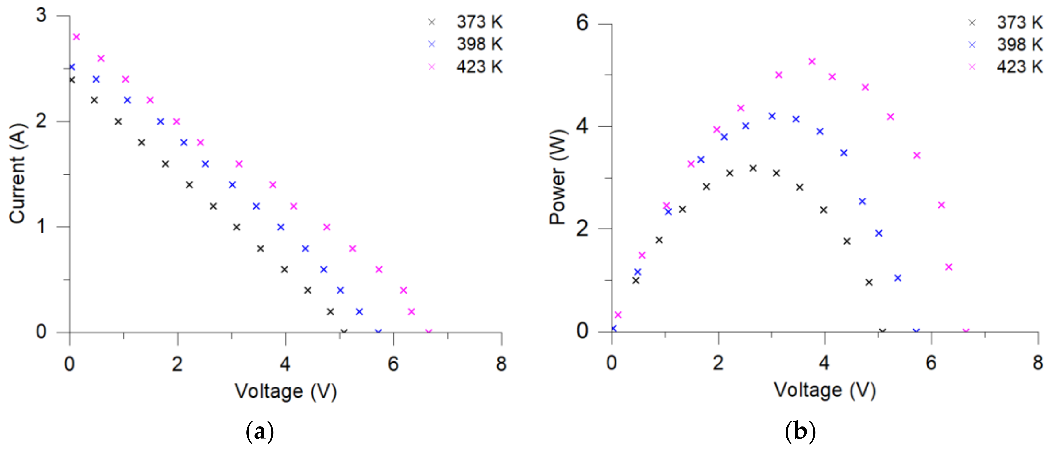
Variations in the voltage and current of TEG No. 4 were connected with the actual phase of the combustion process (including parameters such as the shape of the flame, the amount of burned fuel, and the opening degree of the air throttle which impacted, e.g., the flue gas temperature and its flow). As a result, the presented characteristics were nonlinear (see Figure 12a). Figure 12b shows the P–V characteristic. The maximum power generated in the tested TE module was ca. 5.3 We (when the hot side temperature was at a level of approximately 423 K). Significantly lower power generation was observed when the temperature of the hot side was at a level of 398 K (approximately 4.2 We) and 373 K (approximately 3.2 We).

3.2. Results of the Tests of the Operation Parameters of the TEG No. 5

3.2.1. Variations in the Temperature of the Flue Gas, Hot Surface, and Cooling Water

Figure 13 shows variations in the temperature of the flue gas, the hot surface temperature of the designed heat exchanger, as well as the temperature of the inlet and outlet of the cooling water. In this series, the initial wood input of 4.0 kg was followed by subsequent 1.5 and 2.5 kg inputs realized when the temperature of the flue gas drops below 573 K (that is, 300 °C). The most interesting period is the time between 30 and 140 min which corresponds to the combustion phase. The combustion phase takes place after moisture is driven from the wood and the heat raises the temperature of the wood above ca. 555 K. This is the heat-producing stage, and it is preceded by the initial phase (when the wood is heated to evaporate and eliminate moisture) and followed by the afterburning phase (when the wood residues are burnt with a low heat output rate) [30,31]. Taking into account only the combustion phase, the average difference between the hot surface temperature and the flue gas temperature was equal to ca. 110 K. The average value of the hot surface temperature was ca. 523 K (that is, 250 °C), which was the optimum value from the point of view of thermoelectric modules used in the developed TEG. On the other hand, some fluctuations in the hot surface temperature were observed. These fluctuations resulted from actual burning conditions (the current mass of burned fuel and the current set of air throttle opening, etc.).

3.2.2. The Operational Characteristics of TEG No. 5

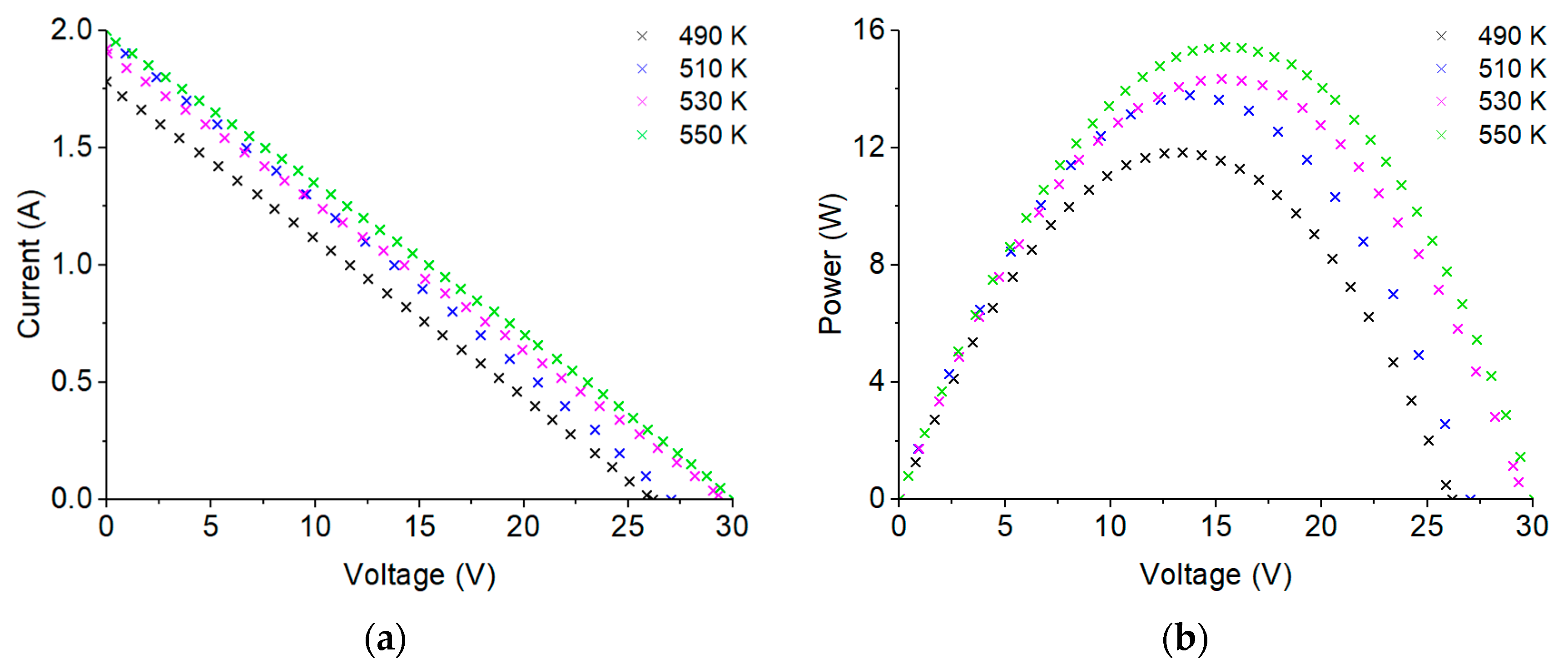
The current-voltage characteristic of the developed TEG (see Figure 14) shows that the short circuit current achieved a maximum value of 2 A, and the open circuit voltage achieved a maximum value of 30 V. As a result of the measured current and voltage values, the P–V characteristics were determined. The maximum power attained was 15.4 We for a matched load current of 1.0 A and a matched load voltage of 15.4 V (thermoelectric modules were connected in series). Assuming this situation, when the maximum power of TEG occurs during the main phase of the stove operation, the energy generated will be at a level of ca. 30 Whe (this is possible to reach by providing proper hot-side and cold-side temperature as well as MPPT system operation). On the other hand, the heat transferred to the water during the main phase of the stove operation (measured during the presented investigation) was ca. 750 Whth.

3.3. Analysis of the Results Obtained during the Tests

3.3.1. Variations in Voltage as a Function of Temperature

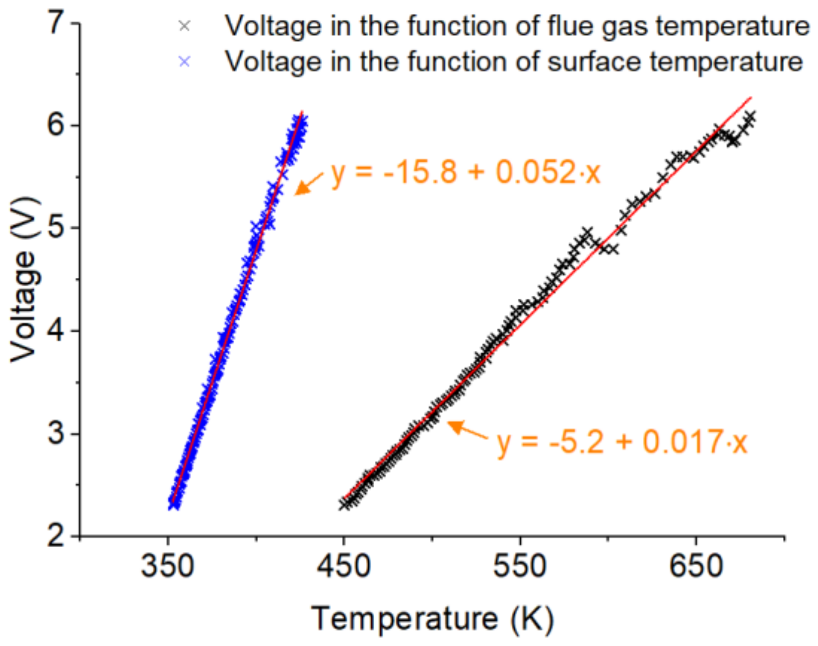
As was observed during the experiments, variations in the output voltage were similar to variations in the flue gas and hot surface temperatures. Consequently, the output voltage can be presented as a function of temperature (see Figure 15). Both the temperature of the flue gas and surface temperature can be used to estimate the voltage generated by TEG No. 4 using linear functions with very good accuracy (R2 = 0.992 for the first case and R2 = 0.997 for the second case, respectively). This information may be useful from the point of view of forecasting the amount of electricity produced in various wood-fired heating devices as well as from the point of view of developing control algorithms for mCHP systems with thermoelectric generators. Of course, the relationships presented are correct assuming certain parameters of heating devices (e.g., nominal power and size of the combustion chamber), fuel combustion parameters (e.g., fuel input), and cooling system operating parameters. On the other hand, rough analysis can be performed for a wide range of domestic wood-fired stoves based on temperature measurements.

3.3.2. Variations in Generated Power as a Function of Temperature

The generated power is strictly dependent on the temperature difference between the hot and cold sides and on the heat flux. Assuming constant parameters of the cooling system, it is possible to determine the power generated in the thermoelectric generator as a function of the flue gas temperature or the hot surface temperature. Figure 16 shows the variations in power generated in TEG No. 4 and TEG No. 5 as a function of the temperature of the flue gas. The linear function in the case of TEG No. 4 means that the flue gas temperature should be higher in order to obtain higher TEG performance. On the other hand, in the case of TEG No. 5, it may be observed that the flue gas temperature reached a proper level (550 K), and the generated power was at the highest possible level. Such an analysis is very useful from the standpoint of assessment of developed thermoelectric generators design limits: for TEG No. 4, these limits have not yet been reached, and the limited capacity was caused by flue gas temperatures that were too low.

3.3.3. Comparative Power Coefficient and Comparative Power to Temperature Coefficient

Direct comparison of TEG No. 4 and TEG No. 5 is not quite easy because different operating conditions occurred during the analyzed combustion processes (biomass burning is a complex process, and its cycle is irregular despite the control system used). Thus, the comparative power coefficient and the comparative power-to-temperature coefficient were calculated for both thermoelectric generators tested using formulas 1 and 2. The results are included in Table 2. By comparing TEG No. 4 and TEG No. 5, it may be observed that CPC differs by only 5.9% (CPC is higher in the case of TEG No. 5), while the difference in CPTC is much more significant (0.028 for TEG No. 5 and 0.012 for TEG No. 4). On the other hand, by including only a single TE module for comparison in both cases of TEG No. 4 and TEG No. 5, the CPTC is significantly higher for TEG No. 4. Based on these results, it may be concluded that TEG No. 5 is characterized by better construction, while TEG No. 4 is equipped with a more efficient (better) TE module. When comparing tested thermoelectric generators with market-available units, significantly higher CPC values were measured for TEG No. 4 and TEG No. 5 than in the case of market-available TEGs (TEG No. 1 was characterized by CPC at a level of 0.42; TEG No. 2—0.31; and TEG No. 3—0.07).

3.3.4. The Economical Aspects of the Operation of the Stove with TEG

In addition to the technical aspects connected with the operation of the tested mCHP system, the economic premises of the proposed solution have to be taken into account. Based on the results obtained, some conclusions may be drawn. On the other hand, since the first version of the TEG was tested (which will be further developed), therefore, some additional assumptions were introduced to the analysis (concerning, inter alia, more TE modules, expected investment costs, or exemplary operation scenarios).
Starting from investment costs, these include the cost of the stove—EUR 1250 (the actual price of the tested unit)—and the estimated cost of a thermoelectric generator— EUR 350 or EUR 500 (see Table 3). As observed, the cost of implementing TEG does not increase the price of a tested wood-fired stove by more than 40%.
The next type of cost is operational costs. In the case analyzed, these costs are related to fuel costs and the cost of energy consumed by the controller, as the well as additional costs of energy consumed by the TEG water-cooling system (if considered). The actual price of pinewood in Poland is ca. 20/32 EUR per stacked m3, which corresponds to ca. 50–80 EUR per Mg (this price was estimated based on the analysis of a dozen offers available online). In order to provide sufficient hot side temperature from the point of view of TEG operation, an initial wood input of 4.0 kg was followed by subsequent 1.5/2.5 kg inputs realized when flue gas temperature drops below 573 K (that is, 300 °C). Consequently, ca. 4.0 kg of pinewood per hour was burned in the combustion phase. The estimated cost of the stove operating under such operation conditions is ca. 0.26 EUR per hour. During economic analysis, the cost of the stove operation can be compared with the cost of natural gas burned in the central heating boiler (one of the most common heat sources in modern residential buildings). From the point of view of the investigations carried out, two main options can be considered: installation of the TEG in the stove in use (option 1) or installation of both the stove and the TEG (option 2). In the case of option 2, the annual savings in heating costs was considered as the difference between the cost of heat generated during natural gas combustion in the central heating boiler and the combustion of wood in the stove. The price of natural gas was assumed to be at a level of 17.9218 EUR per GJ (based on the average price in the EU-27 area for 2020) [32]. A building with an area of 150 m2 and a heat demand of 70 kWhth/(m2·a) was adopted as the reference building.
During the typical operation of the tested stove, the controller takes a power ranged from 1.5 to 5.0 We (it is connected with power consumption by itself and power consumption by an air throttle). The additional power necessary to drive the TEG’s water-cooling system (i.e., circulation pump) should also be included in the calculations if a stand-alone operation of the system is considered. As stated in Section 3.1.2, the average value of energy consumed by the circulation pump may be assumed at a level of ca. 15 Whe per hour. Consequently, depending on the system configuration, the total energy generated in TEG may be treated as an economic profit (when the stove is an additional heat source and the return water from the central heating system is used as the cooling medium) or the difference between the energy generated in TEG and the reduced energy consumption by the water-cooling system (when a stand-alone operation of the system is considered). Both options were included in the analysis. The actual price of electricity was assumed to be at a level of 0.2134 EUR per kWhe (based on the average price in the EU-27 area for the second half of 2020) [32].
By taking into account the above-mentioned data, economic analysis was carried out. The economic indicators in the form of Simple Payback Time (SPBT) and Net Present Value (NPV) were determined using the Equations 3 and 4. The results are presented in Table 4.
Due to the relatively low energy generated in TEG, the estimated payback time in the case of installing a thermoelectric generator to the existing stove ranges from 15.4 to 28.9 years (consequently, NPV is lower than zero). On the other hand, taking into account the installation of the mCHP system (i.e., stove integrated with TEG), the payback time is really attractive (3.3–5.8 years), and NPV ranges from EUR 575.8 to 2165.9. Thus, from an economic point of view, the entire mCHP system should be considered as an interesting alternative (or complement) to fossil-fuelled heat sources.
However, it should be noted that introducing the mCHP system may provide fully or partially network-independent operation of the heating and hot water systems. It is important because of the increasing prices of fossil fuels (i.e., natural gas and coal) and electricity, as well as from the standpoint of avoiding possible periodic interruptions in the access to heat and electricity from the public grid. Moreover, the environmental benefits of using wood-fired mCHP systems (resulting from replacement of natural gas or coal-fuelled heat sources) should be underlined.

4. Conclusions

Power generation with the use of TEG is increasing in popularity due to the decreasing prices of the TE modules and the high costs of consuming electric power from the grid. The results presented in this paper confirm the possibility of using developed thermoelectric generators to generate power from waste heat from wood-fired stoves. The maximum power obtained during the discussed combustion process was 5.3 We and 15.4 We for TEG No. 4 and TEG No. 5, respectively. Two specially introduced factors (CPC and CPTC) allowed concluding that the construction of TEG No. 5 is better than the construction of TEG No. 4, but the performance of installed TE modules is significantly lower. Therefore, in the final version of the TEG, thermoelectric modules characterized by higher efficiency should be introduced, as more items may be installed in order to obtain increased electric power and sufficient levels of current and voltage. Both developed constructions were characterized by a higher CPC value compared to units available in the current market (TEG No. 1, TEG No. 2, and TEG No. 3 described shortly in this paper).
On the basis of the obtained results, an economic analysis was performed. As was shown, from the economic point of view, the best option is to consider the mCHP system as an alternative (or complement) to the fossil-fuelled heat sources. Considering only the installation of TEG on the existing stoves, the payback time ranges from 15.4 to 28.9 years, while it is 3.3 to 5.8 years in the case of the entire mCHP system. On the other hand, in addition to economic aspects, benefits such as network-independent operations (fully or partially) and a reduction in fossil fuels usage should be underlined.
Future investigations should focus on providing the optimum temperature of the hot side of the TEG. It may be realized by developing a dedicated controller, which will control the stream of air blown to the combustion chamber. Of course, the level of the flue gas emission also has to be controlled, and the power generating system should be equipped with a safety system (e.g., an additional throttle and by-pass to avoid overheating). Providing an effective cooling system is also very important. One of the possible options is the return of water from central heating systems (especially systems with underfloor heating).

Funding

This work was carried out under the Subvention from the Faculty of Energy and Fuels, AGH University of Science and Technology in Krakow (no. 16.16.210.476).

Acknowledgments

This work was carried out under the Subvention from the Faculty of Energy and Fuels, AGH University of Science and Technology in Krakow (no. 16.16.210.476). In addition, the research infrastructure of the Center of Energy was used.

Conflicts of Interest

The authors declare no conflict of interest.

Nomenclature

CHPCombined Heat and Power
CO2Carbon Dioxide
CPCComparative Power Coefficient
CPTCComparative Power to Temperature Coefficient
LEDLighting Emitting Diode
LHVLower Heating Value
mCHPMicroscale Combined Heat and Power
NPVNet Present Value
SPBTSimple Payback Time
TEGThermoelectric Generator
TEMThermoelectric Module
WFSWood-fired Stove

References

  1. Noonan, C.W.; Semmens, E.O.; Ware, D.; Smith, P.; Boyer, B.B.; Erdei, E.; Hopkins, S.E.; Lewis, J.; Ward, T.J. Wood stove interventions and child respiratory infections in rural communities: KidsAir rationale and methods. Contemp. Clin. Trials 2020, 89, 105909. [Google Scholar] [CrossRef]
  2. Kryzia, D.; Kuta, M.; Matuszewska, D.; Olczak, P. Analysis of the Potential for Gas Micro-Cogeneration Development in Poland Using the Monte Carlo Method. Energies 2020, 13, 3140. [Google Scholar] [CrossRef]
  3. Zoui, M.A.; Bentouba, S.; Stocholm, J.G.; Bourouis, M. A Review on Thermoelectric Generators: Progress and Applications. Energies 2020, 13, 3606. [Google Scholar] [CrossRef]
  4. Gelbstein, Y.; Davidow, J.; Leshem, E.; Pinshow, O.; Moisa, S. Significant lattice thermal conductivity reduction following phase separation of the highly efficient GexPb1–xTe thermoelectric alloys. Phys. Status Solidi 2014, 251, 1431–1437. [Google Scholar] [CrossRef]
  5. Ben-Ayoun, D.; Sadia, Y.; Gelbstein, Y. High temperature thermoelectric properties evolution of Pb1-xSnxTe based alloys. J. Alloys Compd. 2017, 722, 33–38. [Google Scholar] [CrossRef]
  6. Xing, Y.; Liu, R.; Liao, J.; Zhang, Q.; Xia, X.; Wang, C.; Huang, H.; Chu, J.; Gu, M.; Zhu, T.; et al. High-efficiency half-Heusler thermoelectric modules enabled by self-propagating synthesis and topologic structure optimization. Energy Environ. Sci. 2019, 12, 3390–3399. [Google Scholar] [CrossRef]
  7. Rull-Bravo, M.; Moure, A.; Fernández, J.F.; Martín-González, M. Skutterudites as thermoelectric materials: Revisited. RSC Adv. 2015, 5, 41653–41667. [Google Scholar] [CrossRef]
  8. Riffat, S.B.; Ma, X. Thermoelectrics: A review of present and potential applications. Appl. Therm. Eng. 2003, 23, 913–935. [Google Scholar] [CrossRef]
  9. Lertsatitthanakorn, C. Electrical performance analysis and economic evaluation of combined biomass cook stove thermoelectric (BITE) generator. Bioresour. Technol. 2007, 98, 1670–1674. [Google Scholar] [CrossRef]
  10. Najjar, Y.S.H.; Kseibi, M.M. Thermoelectric stoves for poor deprived regions—A review. Renew. Sustain. Energy Rev. 2017, 80, 597–602. [Google Scholar] [CrossRef]
  11. World Energy Outlook—Topics—IEA. Available online: https://www.iea.org/topics/world-energy-outlook (accessed on 31 August 2021).
  12. Szramowiat-Sala, K.; Korzeniewska, A.; Sornek, K.; Marczak, M.; Wierońska, F.; Berent, K.; Gołaś, J.; Filipowicz, M. The properties of particulate matter generated during wood combustion in in-use stoves. Fuel 2019, 253, 792–801. [Google Scholar] [CrossRef]
  13. Sornek, K. Prototypical Biomass-Fired Micro-Cogeneration Systems—Energy and Ecological Analysis. Energies 2020, 13, 3909. [Google Scholar] [CrossRef]
  14. Mal, R.; Prasad, R.; Vijay, V.K.; Verma, A.R. The design, development and performance evaluation of thermoelectric generator (TEG) integrated forced draft biomass cookstove. Procedia Comput. Sci. 2015, 52, 723–729. [Google Scholar] [CrossRef] [Green Version]
  15. Champier, D.; Bédécarrats, J.P.; Kousksou, T.; Rivaletto, M.; Strub, F.; Pignolet, P. Study of a TE (thermoelectric) generator incorporated in a multifunction wood stove. Energy 2011, 36, 1518–1526. [Google Scholar] [CrossRef] [Green Version]
  16. Mastbergen, D.; Willson, B.; Joshi, S. Producing Light from Stoves using a Thermoelectric Generator. Ethos 2005, 2005, 15–27. [Google Scholar]
  17. Patowary, R.; Baruah, D.C. Feasibility study of TEG-integrated biomass cook stove for electrical power generation specific to rural areas with inadequate electricity. Energy Sour. Part A Recov. Utilizat. Environ. Effects 2019. [Google Scholar] [CrossRef]
  18. Lv, H.; Li, G.; Zheng, Y.; Hu, J.; Li, J. Compact Water-Cooled Thermoelectric Generator (TEG) Based on a Portable Gas Stove. Energies 2018, 11, 2231. [Google Scholar] [CrossRef] [Green Version]
  19. Montecucco, A.; Siviter, J.; Knox, A.R. A Combined Heat and Power System for Solid-fuel Stoves Using Thermoelectric Generators. Energy Procedia 2015, 75, 597–602. [Google Scholar] [CrossRef] [Green Version]
  20. Liu, C.; Chen, P.; Li, K. A 500 W low-temperature thermoelectric generator: Design and experimental study. Int. J. Hydrog. Energy 2014, 39, 15497–15505. [Google Scholar] [CrossRef]
  21. O’Shaughnessy, S.M.; Deasy, M.J.; Doyle, J.V.; Robinson, A.J. Field trial testing of an electricity-producing portable biomass cooking stove in rural Malawi. Energy Sustain. Dev. 2014, 20, 1–10. [Google Scholar] [CrossRef]
  22. Favarel, C.; Champier, D.; Rozis, J.F.; Kousksou, T.; Bédécarrats, J.P. Thermoelectricity—A promising complementarity with efficient stoves in off-grid-areas. J. Sustain. Dev. Energy Water Environ. Syst. 2015, 3, 256–268. [Google Scholar] [CrossRef]
  23. Goudarzi, A.M.; Mazandarani, P.; Panahi, R.; Behsaz, H.; Rezania, A.; Rosendahl, L.A. Integration of Thermoelectric Generators and Wood Stove to Produce Heat, Hot Water, and Electrical Power. J. Electron. Mater. 2013, 42, 2127–2133. [Google Scholar] [CrossRef]
  24. Araiz, M.; Casi, Á.; Catalán, L.; Martínez, Á.; Astrain, D. Prospects of waste-heat recovery from a real industry using thermoelectric generators: Economic and power output analysis. Energy Convers. Manag. 2020, 205, 112376. [Google Scholar] [CrossRef]
  25. Borsukiewicz-Gozdur, A.; Wiśniewski, S.; Mocarski, S.; Bańkowski, M. ORC power plant for electricity production from forest and agriculture biomass. Energy Convers. Manag. 2014, 87, 1180–1185. [Google Scholar] [CrossRef]
  26. Sornek, K.; Filipowicz, M. A study of the applicability of a straw-fired batch boiler as a heat source for a small-scale cogeneration unit. Chem. Process Eng. Inz. Chem. Process. 2016, 37, 503–515. [Google Scholar] [CrossRef] [Green Version]
  27. Żołądek, M.; Figaj, R.; Sornek, K. Energy analysis of a micro-scale biomass cogeneration system. Energy Convers. Manag. 2021, 236, 114079. [Google Scholar] [CrossRef]
  28. Sornek, K.; Filipowicz, M.; Żołądek, M.; Kot, R.; Mikrut, M. Comparative analysis of selected thermoelectric generators operating with wood-fired stove. Energy 2019, 166, 1303–1313. [Google Scholar] [CrossRef]
  29. Available online: https://www.grundfos.com/us (accessed on 21 September 2021).
  30. Vogel, M. Heating with Wood: Principles or Combustion; Montana State University Extension: Bozeman, MT, USA, 2005. [Google Scholar]
  31. Sornek, K.; Filipowicz, M.; Rzepka, K. Study of clean combustion of wood in a stove-fireplace with accumulation. J. Energy Inst. 2017, 90, 613–623. [Google Scholar] [CrossRef]
  32. Eurostat Data. Available online: https://ec.europa.eu (accessed on 21 September 2021).
Figure 1. The principle of thermoelectric generation.
Energies 14 06264 g001
Figure 2. The idea of a power generation system with a wood stove and a thermoelectric generator.
Energies 14 06264 g002
Figure 3. The view of the stove with the thermoelectric generators used during the tests described in [28]: TEG No. 1 (a), TEG No. 2 (b), and TEG No. 3 (c).
Energies 14 06264 g003
Figure 4. The general scheme of the experimental rig.
Energies 14 06264 g004
Figure 5. The combustion chamber of the tested wood-fired stove.
Energies 14 06264 g005
Figure 6. View of the control cabinet (a), electronic load (b), and visualization created in CoDeSys software (c).
Energies 14 06264 g006aEnergies 14 06264 g006b
Figure 7. The simplified scheme of the initial version of the thermoelectric generator dedicated to installation in the flue gas channel (TEG No. 4).
Energies 14 06264 g007
Figure 8. The simplified scheme of the prototype version of the developed TEG dedicated for installation in the flue gas channel (TEG No. 5).
Energies 14 06264 g008
Figure 9. The preliminary construction of the prototype version of the developed TEG dedicated for installation in the flue gas channel (TEG No. 5).
Energies 14 06264 g009
Figure 10. Variations in the temperature of the flue gas at the selected points of the tested stove.
Energies 14 06264 g010
Figure 11. Variations in the TEG output voltage during the combustion process depending on the cooling method (when TEG No. 4 was tested).
Energies 14 06264 g011
Figure 12. I–V (a) and P–V (b) characteristics of the tested TEG No. 4.
Energies 14 06264 g012
Figure 13. Variations in the temperature of the flue gas, the temperature of the hot surface, and the temperature of the cooling water during the combustion process (when TEG No. 5 was tested).
Energies 14 06264 g013
Figure 14. I–V (a) and P–V (b) characteristics of the tested TEG No. 5.
Energies 14 06264 g014
Figure 15. Variations as an output voltage in the function of flue gas temperature and hot surface temperature (on the example of TEG No. 4).
Energies 14 06264 g015
Figure 16. Variations in the generated power as a function of flue gas temperature (on the examples of TEG No. 4 and TEG No. 5).
Energies 14 06264 g016
Table 1. The summary of selected previous research on TEGs integrated with stoves.
AuthorsHeat SourceElectrical Power, WeApplicationDevelopment Status
Lertsatitthanakorn [9]Cooking stove2.4Battery chargingLaboratory tests
Mal et al. [14]Cooking stove5.0Battery charging and lightingLaboratory tests
Champier et al. [15]Multifunction stove9.5Battery chargingLaboratory tests
Patowary and Baruah [17]Cooking stove2.7LightingLaboratory tests
Lv et al. [18]Portable gas stove12.9External loadLaboratory tests
Montecucco et al. [19]Solid-fuel stove27.0Battery charging and power other equipmentLaboratory tests
O’Shaughnessy et al. [21]Cooking stove5.9Battery charging and power other equipmentField tests
Favarel et al. [22]Multifunction stove28.0Power stove’s fanLaboratory tests
Table 2. Comparative power coefficient and comparative power to temperature coefficient.
ParameterTEG No. 4TEG No. 5
Matched power (given by manufacturer), W10.528.8
Matched power (measured during tests), W5.315.4
Matched voltage (measured during tests), V3.815.4
Matched current (measured during tests), A1.41.0
Flue gas temperature (when the matched power was measured), K423550
Comparative power coefficient (CPC), −0.510.54
Comparative power to temperature coefficient (CPTC), W/K0.0120.028
Table 3. The essential parameters of thermoelectric generators assumed by economic analysis.
TEG ParameterVariant 1Variant 2
Type of TE modules, −low-costhigh-efficient
The number of TE modules, −1616
The matched power, We115.2185.6
The cooling medium, −liquid (water)liquid (water)
Temperature difference, K230230
Estimated cost, EUR350500
Table 4. Economic analysis of the proposed mCHP system.
ParameterStand-Alone UnitA Part of the Heating Installation
TEG—Variant 1TEG—Variant 2TEG—Variant 1TEG—Variant 2
Cost of the stove, EUR1250125012501250
Cost of the TEG, EUR350500350500
Assumed heat generation in the stove, kWhth/a10,50010,50063006300
Assumed electricity generation in the TEG, kWhe/a94.2151.856.691.1
The annual saving in heating costs, EUR/a469.6469.6281.8281.8
The annual savings in electricity costs (including both energy self-consumed by the mCHP system and used by domestic appliances), EUR/a20.132.412.119.4
SPBT (only installation of the stove), years2.72.74.44.4
SPBT (only installation of the TEG to the existing stove), years17.415.428.925.8
SPBT (installation of the mCHP system), years3.33.55.45.8
NPV (only installation of the stove), −2376.12376.1926.0926.0
NPV (only installation of the TEG on the existing stove), EUR−194.8−249.8−256.6−350.2
NPV (installation of the mCHP system), EUR2165.92126.3669.4575.8
Publisher’s Note: MDPI stays neutral with regard to jurisdictional claims in published maps and institutional affiliations.