Article

Enhancing the Fault Ride-through Capability of a DFIG-WECS Using a High-Temperature Superconducting Coil

1
Electrical and Electronic Engineering Technology Department, Yanbu Industrial College, Yanbu Al Sinaiyah, Yanbu 46452, Saudi Arabia
2
Discipline of Electrical and Computer Engineering, Curtin University, WA 6102, Australia
3
Department of Electrical Engineering Discipline, Faculty of Engineering, Helwan University, Helwan 11795, Egypt
4
Department of Electrical Engineering, Faculty of Engineering, University of Tabuk, Tabuk 71491, Saudi Arabia
5
Renewable Energy and Energy Efficiency Center (REEEC), University of Tabuk, Tabuk 71491, Saudi Arabia
*
Authors to whom correspondence should be addressed.
Energies 2021, 14(19), 6319; https://doi.org/10.3390/en14196319
Submission received: 20 August 2021 / Revised: 27 September 2021 / Accepted: 28 September 2021 / Published: 3 October 2021

Abstract

:
With the increase in doubly fed induction generator-based wind energy conversion systems (DFIG-WECS) worldwide, improving the fault ride-through (FRT) capability of the entire system has been given much attention. Enhancement of the FRT capability of a DFIG-WECS is conventionally realized by employing a flexible AC transmission system device with a proper control system. This paper presents a non-conventional method for the improvement of the FRT of DFIG-WECS, using a high-temperature superconducting coil interfaced with the DC-link of the rotor and stator side converters through a DC-chopper. A fractional-order proportional-integral (FOPI) controller is utilized to regulate the DC-chopper duty cycle in order to properly manage the power flow between the DC-link and the coil. Two optimization techniques, Harmony Search and Grey Wolf Optimizer, are employed to determine the optimum size of the superconducting coil along with the optimum parameters of the FOPI controller. The effectiveness of the two proposed optimization techniques is highlighted through comparing their performance with the well-known particle swarm optimization technique.

1. Introduction

With the increased penetration of wind-based generation into power networks, major concerns such as poor power quality and a full or partial blackout may arise if a proper control system is not adopted [1,2,3]. The main restriction imposed on wind energy conversion systems (WECSs) is the voltage profile at the point of common coupling (PCC) with the main grid during faults and disturbance events. These voltage restrictions are presented in graphical plots showing the operating and tripping zones during fault events that the fault ride-through (FRT) capability of the WECS must comply with [4].
Doubly fed induction generators (DFIGs) are commonly used in many WECS installations due to their low initial cost, low converter rating and their active and reactive power controllability [5,6,7,8,9]. Despite these advantages, the most concerning downside of DFIGs is their susceptibility to faults at the grid side; in particular, voltage dips that call for the essential enhancement of the DFIG low voltage ride-through (LVRT) capability [8,9].
If not properly controlled, faults at the grid side increase the DFIG rotor mechanical speed, electromechanical torque and the rotor and stator currents. Under such conditions, the WECS must be disconnected to protect the converter switches, DFIG and wind turbines [8,9]. However, this may result in partial or full blackout, especially for large WECSs.
Flexible AC transmission system (FACTS) devices have been widely utilized to improve the FRT capability of DFIG-WECS [9,10,11]. These devices are used to modulate the active and reactive power at the PCC to maintain the voltage and the rotor speed within permissible limits identified by the grid codes. Some examples of FACTS devices used in this regard include static synchronous compensators (STATCOMs) [12], unified power flow controllers (UPFCs) [10], dynamic voltage restorers [11], battery storage [12] and high-temperature superconductors (SCs) [12,13].
A comparison of the performance of STATCOM, battery storage and SC in improving the FRT capability of WECS-DFIG is presented in [14]. The comparison reveals the effectiveness and superiority of the SC over the STATCOM and battery storage. The superconductor has virtually zero resistance, and hence its efficiency is much higher than any other FACTS device. It also features high storage capacity, rapid response to system faults and the ability to modulate both active and reactive power individually in four quadrant operational modes.
A high temperature SC, which is more affordable than low temperature SC, has recently been used to enhance the FRT capability of a DFIG-WECS [12,13,14]. The SC is interfaced to the DC-link of the DFIG back-to-back converters by a DC-chopper. Through proper control of the DC-chopper duty cycle, energy exchange between the superconductor and the DC-link can be regulated.
The two factors limiting the practical application of superconductors in WECSs include the high cost and the sensitivity of the control system driving the DC-chopper. These two factors can be handled through proper optimization for the SC size along with the proper selection and design of the controller, which is the main contribution of this paper.
Although the proportional–integral (PI) controller has been widely adopted in various control systems [15,16] due to its simple structure, the fractional order PI (FOPI) controller can provide better performance with easy implementation [17]. FOPI is introduced to control voltage source converters used in microgrid applications [8,18].
Tuning the control parameters along with the optimization of other parameters of non-linear complex systems is not a straightforward task. Classical and conventional mathematical methods such as linear programming cannot solve these complex problems effectively and guarantee optimum global solution [19]. As such, various optimization techniques have been introduced to handle such problems. Among them, genetic algorithms (GA) and particle swarm optimization (PSO) are considered as benchmarking for optimization techniques [19].
Optimization techniques are presented in the literature to tune the conventional PI control parameters. For instance, PSO is employed in [20,21] to solve a multi-objective function comprising the SC size and the PI control parameters.
Recently, several modern evolutionary computing techniques have been used in various power system applications including optimum design, size and control parameters calculation. Three up-to-date optimization methods: Harmony Search (HS), Modified Flower Pollination Algorithm, and Electromagnetic Field Optimization, are employed for fine-tuning the PI control parameters to improve the power quality of fuel cells for on-grid applications [22]. Another recent method used to optimize the conventional PI control parameters for a DFIG-WECS application is the grouped Grey Wolf Optimizer (GWO) [23].
In this paper, two modern optimization techniques (HS and GWO) are used for optimum tuning of FOPI control parameters. Moreover, the same techniques are used to identify the optimum size of the proposed SC. The performance of the two optimization techniques is compared with the PSO, as one of the benchmarks for optimization methods [19].
HS is one of the recent optimization methods that has been proposed in a few control systems applied to WECSs. Based on the results reported in [22], HS is found to be more effective than PSO and GA. On the other hand, GWO has been reported to be of better efficiency than the other seven optimization techniques [23].
From the above discussion, the main contribution of this paper can be summarized as below:
  • Enhancing the FRT capability of a WECS using a non-conventional method; high-temperature SC of solenoidal structure;
  • Introducing a new application for an FOPI controller in WECS;
  • Adopting two new optimization techniques; HS and GWO to determine the optimum design of the proposed high-temperature SC and the FOPI control parameters;
  • Presenting a comparison of HS and GWO techniques and the PSO to highlight the effectiveness of the employed methods.

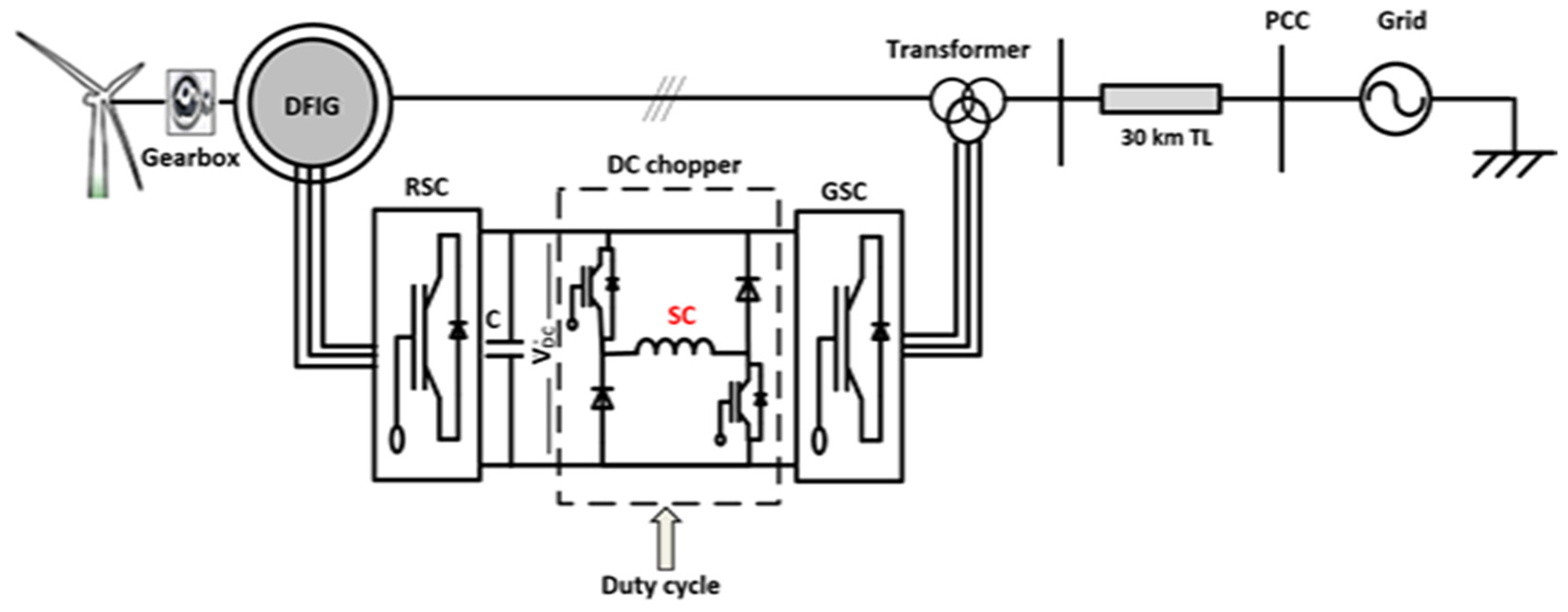
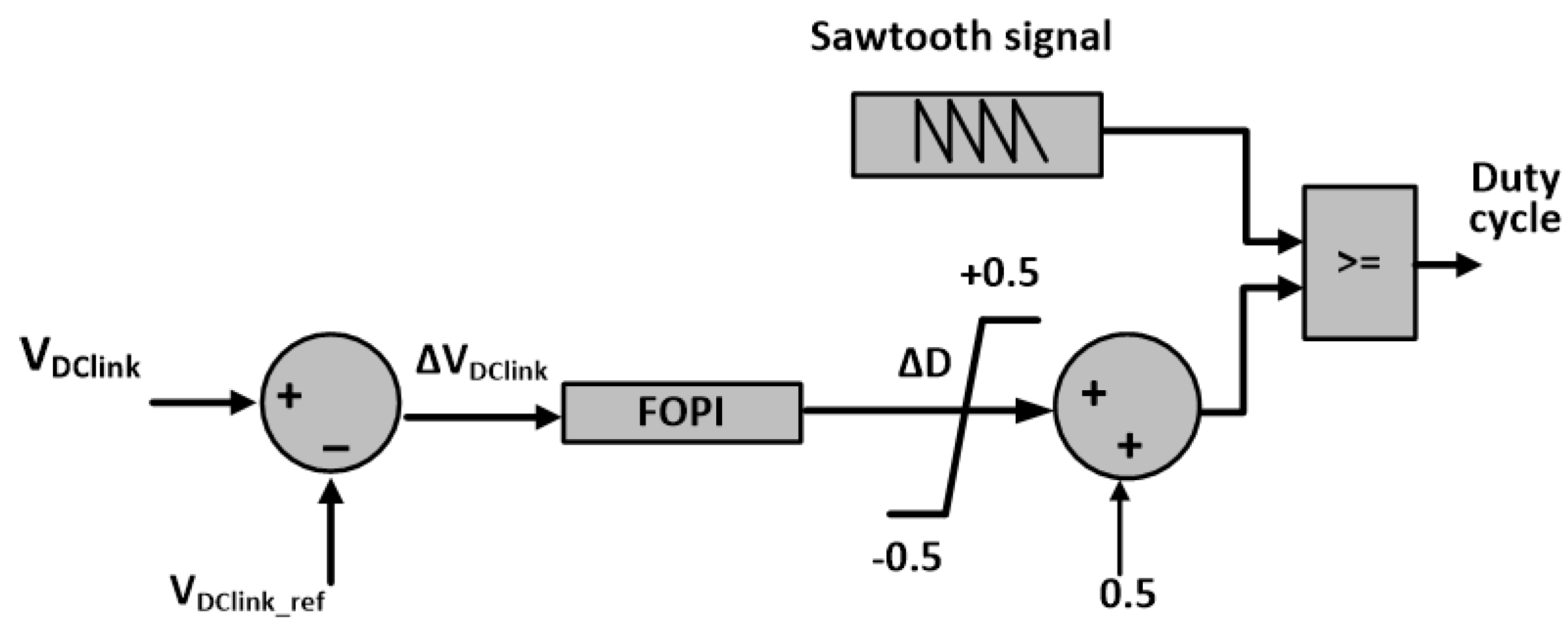
2. System under Study and Proposed Controller

The studied DFIG-WECS is shown in Figure 1. The WECS comprised six DFIG generators, 1.5 MW each with rated voltage and frequency of 0.575 kV and 60 Hz. The stators of the DFIGs were connected to the electricity grid, represented as an infinite bus of constant voltage (120 kV) and frequency (60 Hz), through a three-phase step-up coupling transformer and a 30 km transmission line (TL). The rotors were connected to the low voltage side of the coupling transformer through two back-to-back converters: rotor side converter (RSC) and grid side converter (GSC), connected by a DC-capacitor link. Data of the system under study are listed in Table A1 and Table A2 in the Appendix A.
The proposed high--temperature SC was interfaced to the DC-link of the GSC and RSC via a DC-chopper whose duty cycle was regulated to control the energy exchange between the coil and the system. Through a proper regulation to this energy exchange, the FRT capability of the WECS during fault incidents can be improved, as will be elaborated below.
The proposed FOPI controller was used to enhance the FRT capability of the DFIG during fault events through regulating the duty cycle of the DC-chopper. During fault events and without the use of any controller, the DC-link voltage was expected to exhibit a significant oscillation that resulted in severe consequences to the entire system. By introducing optimally designed SC with a DC-chopper duty cycle regulated by an FOPI controller, a rapid regulation to the DC-link voltage was achieved. The proposed controller is as shown in Figure 2. In the proposed control system, the measured value of the DC-link (VDClink) was compared to a reference voltage, VDClink_ref (1.15 kV in the studied system) to generate an error signal ΔVdc that was fed into the FOPI. The output of the FOPI controller was a regulated duty cycle deviation (ΔD) which was normalized between 0 and 1 and compared to a sawtooth signal to create a proper value for the DC-chopper duty cycle. The FOPI controller had three parameters, integration fractional order (λ), proportional constant (Kp) and integral constant (Ki) that are calculated below.

3. Evolutionary Computing Techniques

Three optimization techniques were presented to optimize the SC size and identify the FOPI control parameters. The main aim of these optimization techniques was to find the minimum SC size with minimum initial energy storage capacity along with the fine-tuning of the FOPI control parameters (Kp, Ki and λ) in order to improve the FRT capability of the entire system during disturbance and fault events.
In this regard, a multi-objective function J was formulated by considering the SC size (inductance, L s c ), initial current in the SC ISC0 and the FOPI control parameters. The three optimization methods, HS, GWO and PSO, were used to minimize this objective function and thus identify the minimum SC rating with the least error in the DC-link voltage, ΔVdc. Hence, the proposed objective function comprised two terms: one was for the SC design and the other term was related to the error in the DC-link voltage as given by (1).
J = W 1 . E 0 + W 2 | Δ V d c | d t , E 0 = 0.5 L s c I s c o 2
Subject to the below design constrains:
0.001 H L s c 10 H ,
1   k A I s c o 5   k A , and the FOPI three control parameters (Kp, Ki and λ) are all > 0. where I s c o is the initial current within the SC and W 1 and W 2 are arbitrary weighting factors that are selected as 0.5 and 1, respectively.
The objective function was non-linear and complex as it comprised five parameters, two related to the SC rating (ISCO, LSC) and three for the FOPI control parameters (Kp, Ki and λ). To solve such function, linear programming methods cannot provide an optimal global solution [8]. On the other hand, evolutionary computing techniques are the most suitable methods to solve such problems. In this paper, two modern optimization techniques (HS and GAW) were used to solve this problem. A comparison between these two methods and another well-known method, PSO, is presented to reveal the effectiveness of the two methods. The three methods are briefly elaborated below.
PSO is a well-known optimization method that has many applications in power system optimization [24,25,26,27]. PSO was employed in the SC design and optimal control of classical PI controller in [21].
HS is one of the modern evolutionary methods that can find many applications in power systems. HS was inspired by pitches grouping to attain leading harmony in musical organizations having to be amongst three playing dominion rules [28,29]:
(i)
Play any pitch concord as of the memory;
(ii)
Play any neighboring pitches of the pitch HS as of the memory;
(iii)
Play irregular pitch from the conceivable pitch.
In every variable selection from the HS algorithm imitation, the best (optimum) value searching procedure depends on the selection of a value and its adjacent ones from the HS memory along with a random one from a possible range. Two main parameters are used to govern the HS algorithm; harmony memory considering rate (HMCR) and pitch adjusting rate (PAR). As shown in the flow chart of Figure 3, the first step in the HS is the initialization of the five unknown parameters of the objective function J by assuming random values within the limit of the designated ranges. Following the initializing process, the objective function is computed using (1). Harmony Memory (HM) matrix is then formulated as below.
H M = [ L s c 1 I s c o 1 K p 1 K i 1 λ 1 L s c 2 I s c o 2 K p 2 K i 2 λ 2 · · · · · · · · · · · · · · · L s c H M S I s c o H M S K p H M S K i H M S λ H M S ]
The HM matrix comprises five columns, three for the FOPI control parameters and two for the SC inductance and initial current. Each row in the HM matrix is a progressed harmony vector primarily based on the HCMR and PAR parameters. The updated process on the current harmony is conducted using (3).
x i n + 1 = x i n + r a n d B W
where x i n is the current harmony vector for all unknowns, x i n + 1 is the updated harmony vector, rand is a random value in the range of (0, 1) and BW is an arbitrary distance bandwidth.
The updating process is repeated until a minimum possible value for the objective function is obtained or the maximum search number is reached.
GWO is another optimization technique that can be adopted in some power system applications [28,29]. This optimization technique is inspired by grey wolf social behavior which is based on leadership hierarchy structure. Grey wolves live in groups, with each group containing 5 to 12 wolves. In light of the chasing methodology of wolves, they can be arranged into four classifications. The first class is the alpha class (α), sometimes called dominant wolves. The wolves in this class have full authority to take decisions in all aspects of the group behavior, such as chasing time, chasing arrangement, resting time and place. They give strict decisions and instructions to the other wolves in the group.
The second class that follows the alpha is the beta (β). Wolves in this class help and provide advice to the alpha class in taking decisions, and replace the wolves in the alpha class in instances of absence or passing away. The third class is delta (δ), known as subordinate wolves. This class includes the elders, sentinels, hunters, scouts, and caretaker wolves.
Delta wolves look after the alpha and beta wolves and oversee the next level wolves. The omega (ω) class comprises the wolves in the most inferior position. These wolves must follow the instructions of all other classes. Omega wolves are not critical members but sometimes help others in facing internal issues. According to [22,29], the grey wolves’ chasing technique is as follows: tracking, chasing, moving toward the prey, pursuing, surrounding, pestering the prey until a point when it stops moving, and finally attacking the prey.
The mathematical modelling of the GWO chasing technique is as below [24,30]:
D = | C   X p ( t ) X ( t ) |
X   ( t + 1 ) = X P   ( t ) A D
where X p ( t ) ,   X ( t ) represent the position vector of the victim and grey wolf at any iteration step t, respectively, whereas A and C are two vectors that are calculated from:
A = 2 a   r 1 a
C = 2 r 2
The vector a is a linear decreasing vector from 2 to 0 over the iteration process and the two vectors r 1 and r 2 are of random values in the range [0, 1].
In GWO, the initial best three solutions are saved and the other classes (including ω) are forced to update their positions to the best agent. The update is performed according to (8).
D α = | C   X α X | ,   D β = | C   X β X | ,   D γ = | C   X γ X |
Then, the average of the best three positions as given by (9) is considered as the final best position.
X   ( t + 1 ) = X 1 + X 2 + X 3 3
The flow chart of the GWO process is shown in Figure 4.

4. Results and Discussions

The convergence profiles of the objective function J using the three proposed optimization techniques over 150 iteration steps are shown in Figure 5. The results indicated that the GWO and HS provided better fitness than PSO with a superiority of GWO in converging to a minimum value of the objective function more rapidly than the other two techniques. The calculated SC size along with the FOPI control parameters using the three optimization methods are listed in Table 1. The table reveals that the least SC rating was obtained when employing GWO.
To test the effectiveness of the obtained results (minimum size of the SC along with the FOPI optimal parameters) using the three optimization techniques, two case studies were investigated: voltage swell and three-phase short circuit fault at the PCC of the system under study.

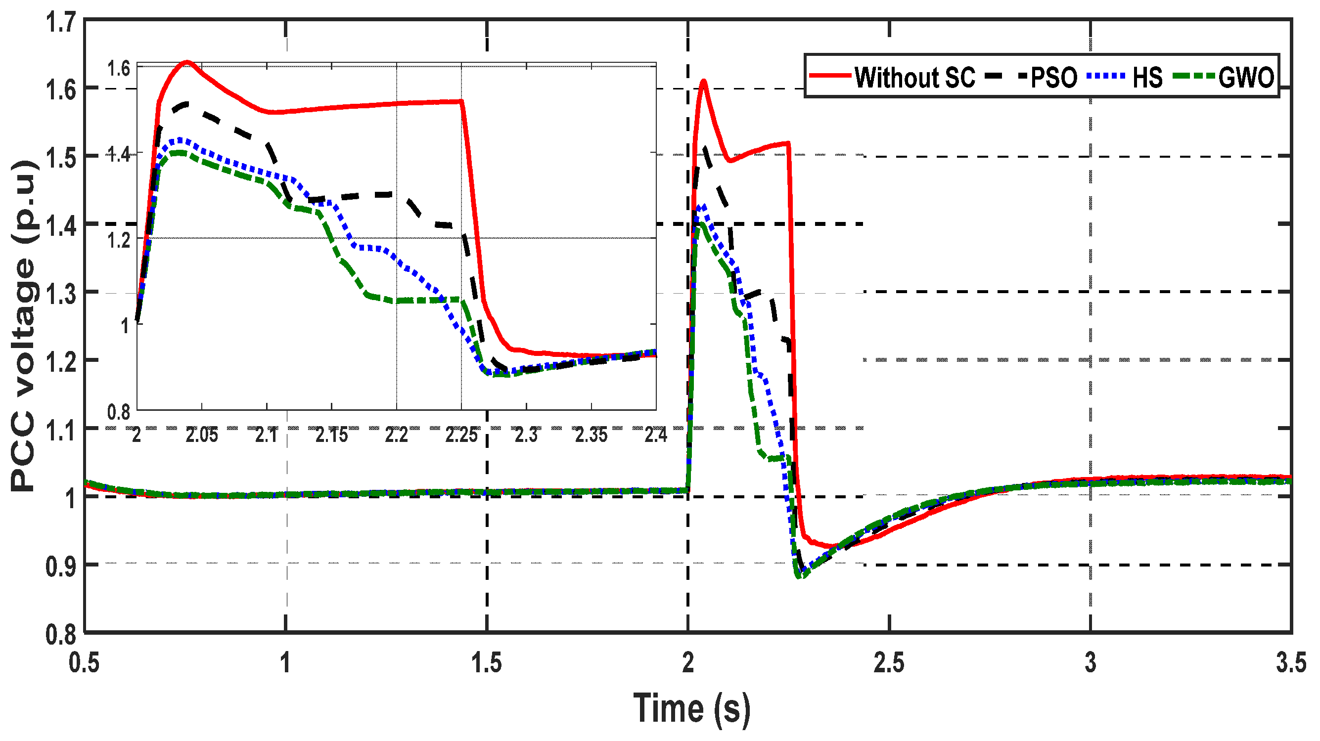
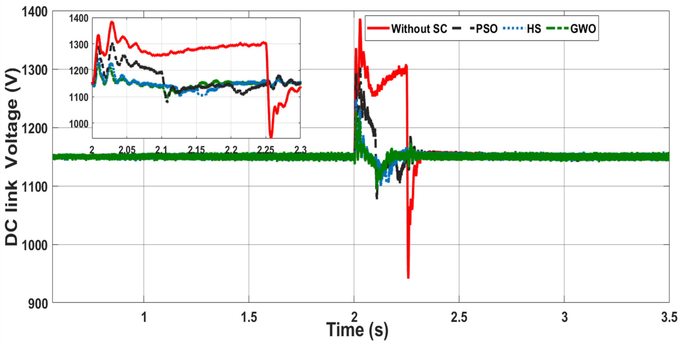
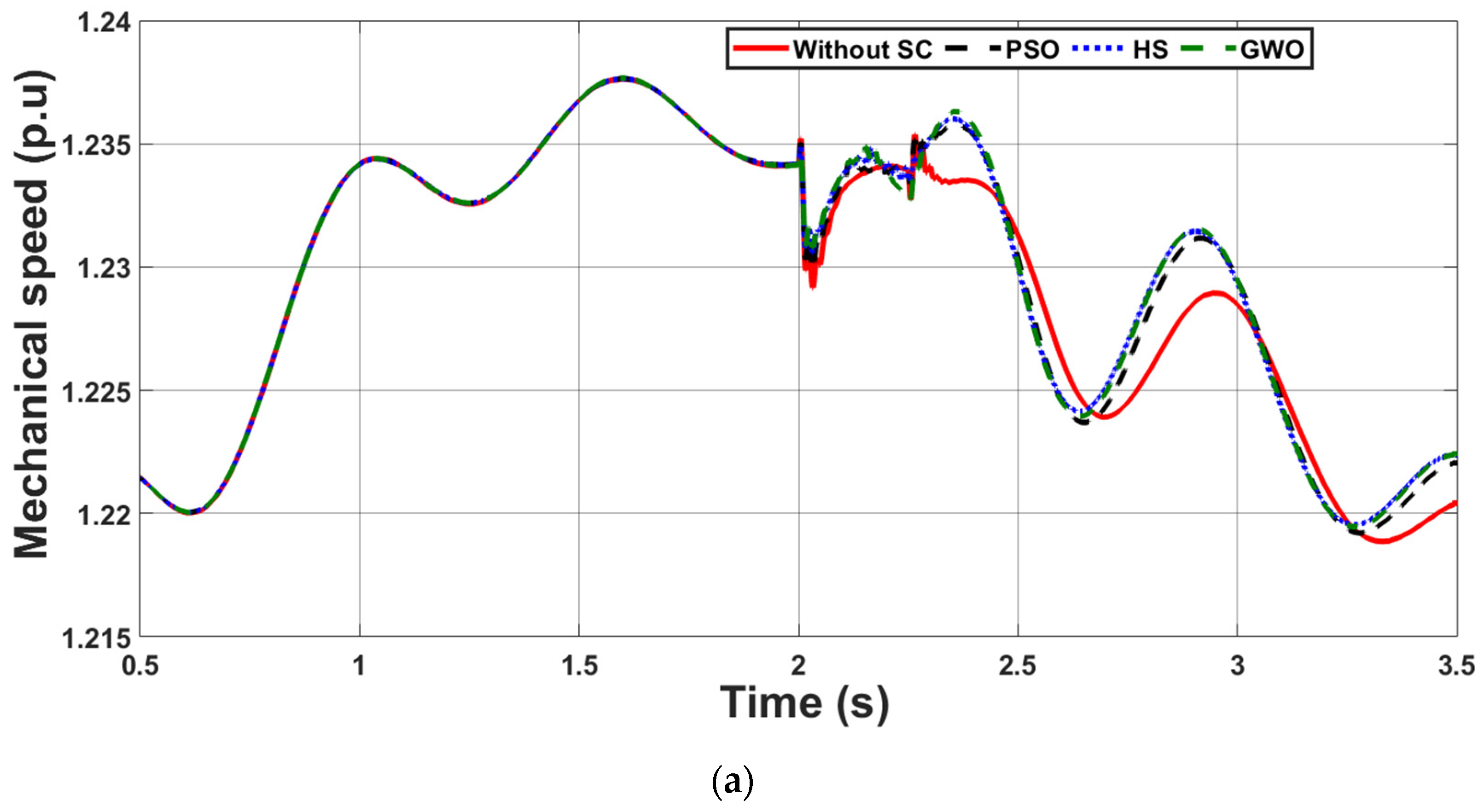
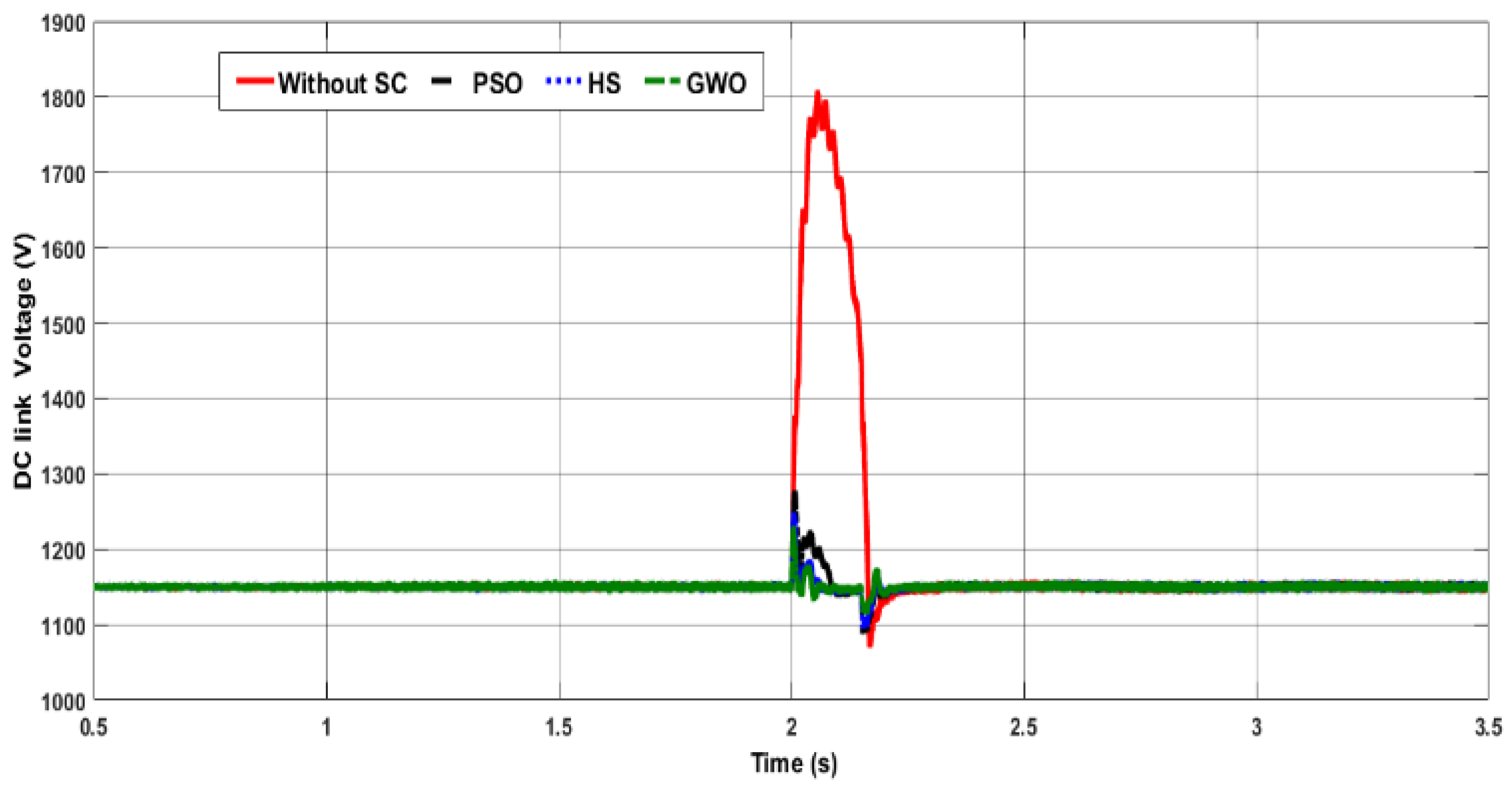
4.1. Case Study 1: Voltage Swell

In this case study, a severe voltage swell of 50% increment in the PCC voltage level, as shown in Figure 6, was assumed to take place at t = 2 s and last for 15 cycles. Without connecting the proposed SC and associated controller, the DC-link voltage shown in Figure 7 exhibited more than 13% increment above its nominal value with a maximum overshooting reaching 121% at t = 2 s. This increase in the DC-link voltage may destroy the capacitor that links the grid and rotor side converters of the DFIG or call for the disconnection of the wind turbines from the system. By using the proposed SC and the FOPI controller with the calculated parameters by the three optimization techniques, the voltage waveforms at the PCC and the DC-link were improved, as depicted in Figure 6 and Figure 7, respectively. It can be observed that with the proposed SC, the overshooting in the DC-link voltage was significantly reduced, particularly when the parameters of the GWO were used, as illustrated in Figure 7. The generator’s active and reactive powers during the voltage swell event are shown in Figure 8. Due to the voltage swell at the PCC, the generated active power exhibited significant oscillations during the swell event (Figure 8a) and excess reactive power of about 1.4 pu was absorbed by the DFIGs as shown in Figure 8b. With the use of the proposed and optimized SC, the profiles of the active and reactive power were improved, particularly when the design parameters calculated by the GWO were employed.
Following the fluctuation in the generated active power, the rotor mechanical speed along with the electromagnetic torque also exhibited significant oscillations, as shown in Figure 9. These oscillations, without adding an SC to the system, may have an adverse impact on the mechanical parts of the generator and the turbine’s blades. Mechanical oscillations were slightly improved when the proposed SC was connected.

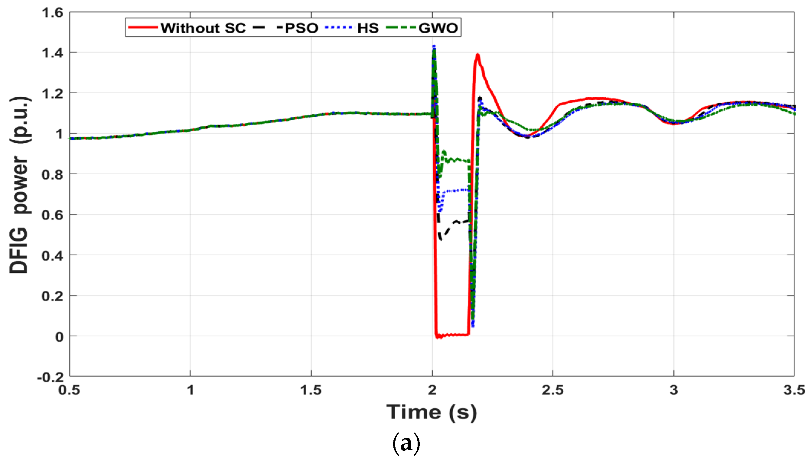
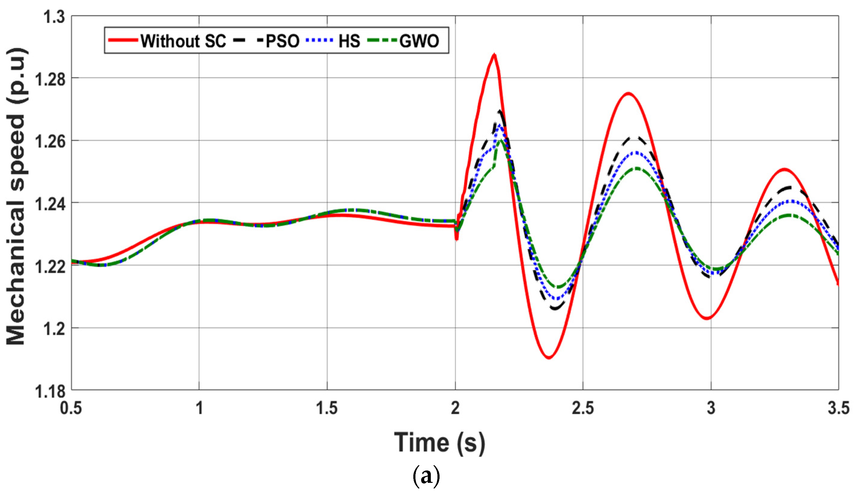
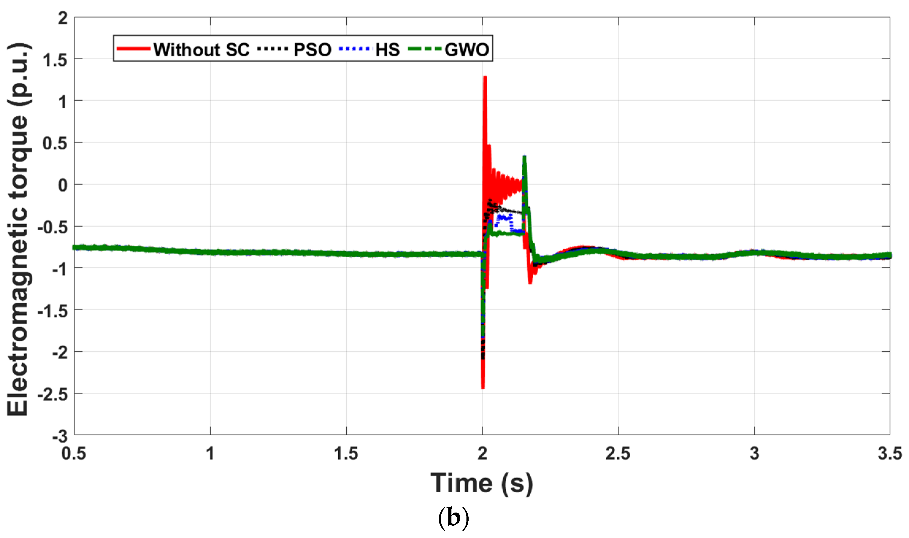
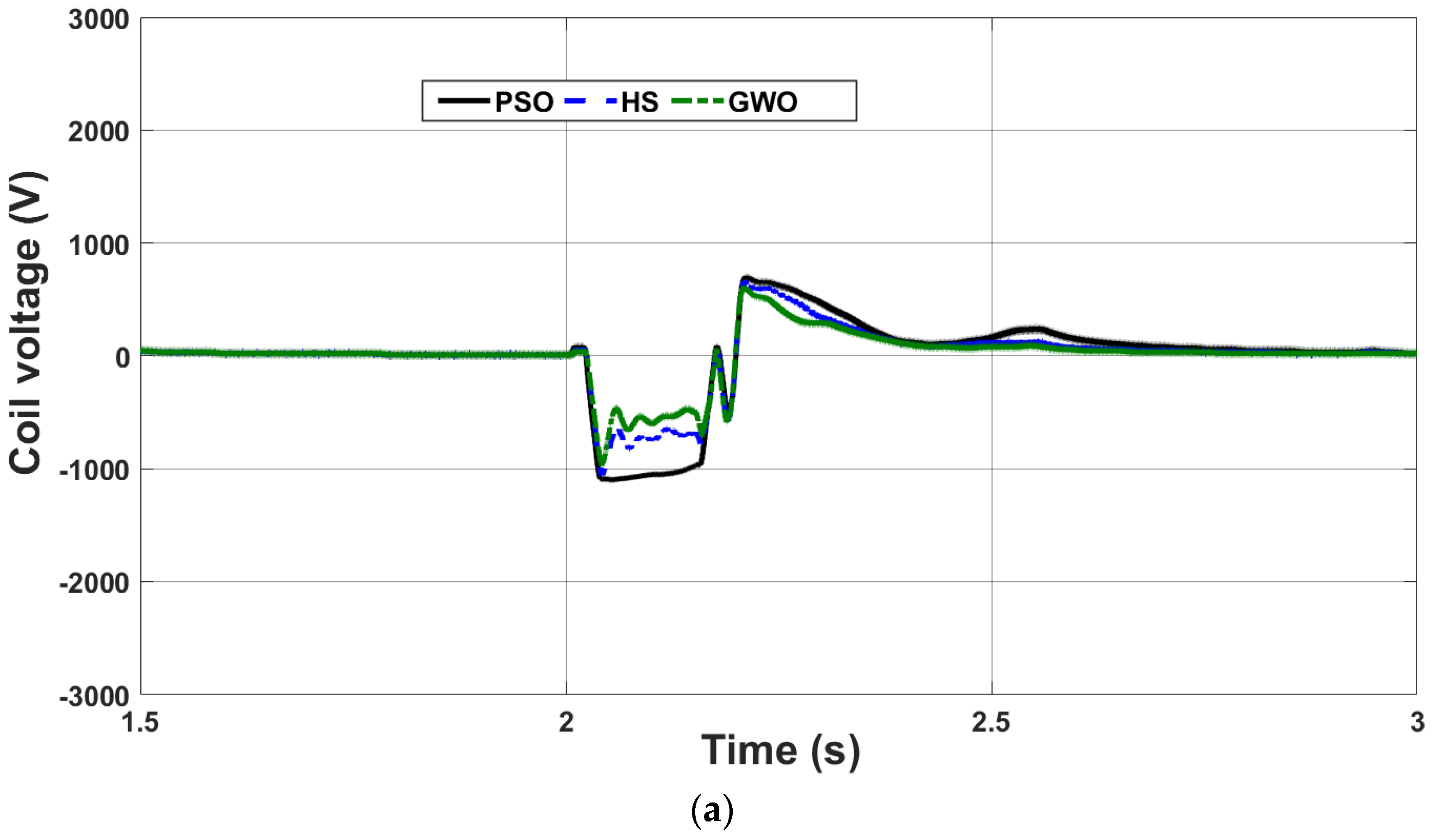
4.2. Case Study 2: Three-Phase Short Circuit Fault

In this case study, a bolted three-phase short circuit fault was assumed to take place at the PCC at t = 2 s and last for 15 cycles, as shown in Figure 10.
The severe reduction in the voltage level violated most grid codes, such as the Spain and USA codes that are shown in Figure 10. This violation called for the disconnection of the wind turbines to prevent any possible damages. With the proposed control system, both active and reactive power at the PCC were regulated due to the energy exchange between the coil and the DC-link. As a result, the PCC voltage profile was enhanced and maintained within a safe margin in regard to the two mentioned codes, as shown in Figure 10. The results showed that the parameters calculated by the GWO and HS provided better performance than that calculated by the PSO.
The DC-link voltage encountered a significant increase that reached 157% of its nominal value if no control scheme was connected. With the connection of the SC and proposed controller, the DC-link voltage was almost kept at its nominal level, regardless of the short circuit fault at the PCC, as shown in Figure 11. Control sensitivity analysis through measuring the maximum overshooting, settling time, and steady-state error of the DC-link and the PCC voltages for this case study is given in Table 2. Results in this table revealed that the system performance when using the optimized parameters obtained from GWO was better than using the parameters obtained from PSO and HS methods.
The drop in the generator terminal voltage resulted in a significant decline in the generated active power and an increase in the reactive power to compensate the voltage reduction as shown in Figure 12. With the connection of the SC, active power was injected by the coil, which raised the power at the PCC to about 0.57 pu when PSO was used, to 0.65 pu when HS was used, and to 0.85 pu when GWO was employed to optimize system parameters. The reactive power profile was also improved with the connection of the SC.
The three-phase fault increased the shaft speed (Figure 13a) to 1.289 pu without the connection of the SC. The electromagnetic torque also increased with significant oscillations as shown in Figure 13b. With the proposed controller, the maximum shaft speed during the fault reached 1.27 pu, 1.265 pu and 1.26 pu by employing the control parameters obtained using the PSO, HS and GWO, respectively, and the profile of the electromagnetic torque was improved.
The coil performance during this case study is illustrated in Figure 14. During normal operation, the voltage across the coil was maintained at zero level while the SC current was kept at its maximum positive level. This is because the duty cycle was adjusted by the controller to be 0.5 and based on the relation between the coil and DC-link voltages, V c = ( 1 2 D ) V D C l i n k , the voltage across the coil terminals became zero [8]. Under such normal conditions, there was no energy transfer between the coil and the system. Upon the occurrence of the fault at t = 2 s, the SC current, which is always unidirectional, dropped with a negative slope. This generated a voltage across the coil proportional with the rate of change of the current, i.e., with a negative polarity that facilitated the stored energy in the coil to be transferred to the system. It is worth noting that although the minimum SC size was obtained using GWO, this size provided the best performance because of the fine-tuning of the FOPI control parameters conducted by the GWO method.

5. Cost Analysis

The high cost of low-temperature superconducting materials is dominated by the cryogenic system that uses liquid helium to maintain the conductor within a temperature less than 30 K. With the advancement of high-temperature-based superconductors, more affordable liquid nitrogen is employed by the cryogenic system to maintain the coil temperature within the range of 77 K to 160 K.
According to [31,32], the cost of a superconducting magnetic energy storage unit is estimated to be in the range of 7% to 25% of the overall cost of the wind energy conversion system it is connected to. It is worth noting that this cost includes the power transformer and the converter that interface the coil to the system. In this paper, no additional power transformer nor power electronic converters were required. The proposed high-temperature superconductor was interfaced to the system through the already existing converters of the DFIG-WECS, which reduced the implementation cost. Moreover, recent technology has been developed to enable superconductors to function at room temperature [33], which will promote the applications of superconducting materials in power systems and other industries such as electromagnetic forming, wireless energy transfer and various WECS [34,35,36].

6. Conclusions

This paper presents two new optimization techniques, HS and GWO, to optimize the design and control parameters of an SC and FOPI to be used to enhance the fault ride-through capability of a DFIG-based WECS. Through a proper objective function, comprising the size of the SC and the error in the DC-link voltage, the two optimization techniques were used to minimize the SC size and fine-tune the FOPI control parameters. The obtained results can be summarized in the below bullet points:
  • GWO featured superior optimization ability to HS and the conventional PSO techniques;
  • Although a minimum SC size was obtained using GWO, the two case studies investigated in this paper demonstrated that the performance of the DFIG-WECS with parameters calculated by GWO was the best among the other two techniques. This was attributed to the adequate tuning and proper calculation of the FOPI control parameters;
  • The proposed method can be used for new and existing WECS installations to enhance the FRT capability of the DFIG during fault and disturbance events;
  • Although the cost of high-temperature superconductors was more affordable than low-temperature superconductors, the cost was still relatively high due to the cryogenic system. With the rapid advancement in superconducting materials, several applications of SC in power systems will be seen in the very near future.

Author Contributions

Conceptualization, M.I.M. and A.A.-S.; methodology, M.I.M. and A.A.-S.; software, M.I.M.; validation, M.I.M. and A.A.-S., M.M.I., H.A. and A.F.; formal analysis, M.I.M. and A.A.-S.; investigation, M.M.I., H.A. and A.F.; data curation, M.I.M.; writing—original draft preparation, M.I.M.; writing—review and editing, A.A.-S.; visualization, M.M.I., H.A. and A.F.; supervision, A.A.-S.; project administration, M.M.I., H.A. and A.F.; funding acquisition, A.A.-S. and M.I.M. All authors have read and agreed to the published version of the manuscript.

Funding

This research received no external funding.

Informed Consent Statement

Not applicable.

Data Availability Statement

Not applicable.

Conflicts of Interest

The authors declare no conflict of interest.

Appendix A

Table A1. DFIG data.
ParameterValue
Rated power1.5 MW
Rated voltage575 V
Rated frequency60 Hz
Stator resistance0.0045 Ω
Stator inductance0.0357 H
Rotor resistance0.0032 Ω
Rotor inductance0.033 H
Mutual inductance0.575 H
Table A2. Transmission line data.
Length, km.R, Ω/kmL, H/kmC, F/km
300.11531.05 × 10−311.33 × 10⁻⁹

References

  1. Yunus, A.M.S.; Abu-Siada, A.; Masoum, M.A.S. Improving Dynamic Performance of Wind Energy Conversion System using Fuzzy-Based Hysteresis Current Controlled SMES. IET Power Electron. 2012, 5, 1305–1314. [Google Scholar] [CrossRef] [Green Version]
  2. Yunus, A.M.S.; Abu-Siada, A.; Masoum, M.A.S. Improvement of LVRT Capability of Variable Speed Wind Turbine Generators Using SMES Unit. In Proceedings of the IEEE Innovation Smart Grid Technologies Conference, Perth, WA, USA, 13–16 November 2011; pp. 1–7. [Google Scholar] [CrossRef]
  3. Ding, Y.; Singh, C.; Goel, L.; Østergaard, J.; Wang, P. Short-term and medium-term reliability evaluation for power systems with high penetration of wind power. IEEE Trans. Sustain. Energy 2014, 5, 896–906. [Google Scholar] [CrossRef]
  4. Nordel Connection Code Wind Turbines. Available online: https://www.wind-energy-the-facts.org/grid-codes-and-essential-requirements-for-wind-power-plants.html (accessed on 15 January 2007).
  5. Abad, G.; Lopez, J.; Rodriguez, M.; Marroyo, L.; Iwanski, G. Doubly Fed Induction Machine: Modeling and Control for Wind Energy Generation; Wiley: Hoboken, NJ, USA, 2011. [Google Scholar]
  6. Jadhav, H.T.; Roy, R. A comprehensive review on the grid integration of doubly fed induction generator. Int. J. Elect. Power Energy Syst. 2013, 49, 8–18. [Google Scholar] [CrossRef]
  7. Semen, S.; Niiranen, J.; Kanerva, S.; Arkkio, A.; Saitz, J. Performance study of a doubly fed wind-power induction generator under network disturbance. IEEE Trans. Energy Convers. 2006, 21, 883–890. [Google Scholar] [CrossRef]
  8. Mosaad, M.I.; Abu-Siada, A.; Elnaggar, M. Application of Superconductors to Improve the Performance of DFIG-based WECS. IEEE Access J. 2019, 7, 103760–103769. [Google Scholar] [CrossRef]
  9. Mosaad, M.I.; Alenany, A.; Abu-Siada, A. Enhancing the performance of wind energy conversion systems using unified power flow controller. IET Gener. Transm. Distrib. 2020, 14, 1922–1929. [Google Scholar] [CrossRef]
  10. Mosaad, M.I.; Sabiha, N.A. Ferroresonance Overvoltage Mitigation using STATCOM for Grid-Connected Wind Energy Conversion Systems. J. Mod. Power Syst. Clean Energy 2020. [Google Scholar] [CrossRef]
  11. Mossad, M.I. Model Reference Adaptive Control of STATCOM for Grid-Integration of Wind Energy Systems. IET Electr. Power Appl. J. 2018. [Google Scholar] [CrossRef]
  12. Wessels, C.; Gebhardt, F.; Fuchs, F.W. Fault ride-through of a DFIG wind turbine using a dynamic voltage restorer during symmetrical and asymmetrical grid faults. IEEE Trans. Power Electron. 2011, 26, 807–815. [Google Scholar] [CrossRef] [Green Version]
  13. Guo, W.; Xiao, L.; Dai, S. Enhancing low-voltage ride-through capability and smoothing output power of DFIG with a superconducting fault-current limiter-magnetic energy storage system. IEEE Trans. Energy Convers. 2012, 27, 277–295. [Google Scholar] [CrossRef]
  14. Rahim, A.H.M.A.; Nowicki, E.P. Supercapacitor energy system for fault-ride through of a DFIG wind generation system. Energy Convers. Manag. 2012, 52, 96–102. [Google Scholar] [CrossRef]
  15. Yunus, M.S.; Abu-Siada, A.; Mosaad, M.I.; Albalawi, H.; Aljohani, M.; Jin, J.X. Application of SMES Technology in Improving the Performance of a DFIG-WECS Connected to a Weak Grid. IEEE Access 2021, 9, 124541–124548. [Google Scholar] [CrossRef]
  16. Viola, J.; Angel, L.; Sebastian, J.M. Design and robust performance evaluation of a fractional order PID controller applied to a DC motor. IEEE/CAA J. Autom. Sin. 2017, 4, 304–314. [Google Scholar] [CrossRef]
  17. Zhong, J.; Li, L. Tuning Fractional-Order PIλDμ Controllers for a Solid-Core Magnetic Bearing System. IEEE Trans. Control. Syst. Technol. 2015, 23, 1648–1656. [Google Scholar] [CrossRef]
  18. Pullaguram, D.; Mishra, S.; Senroy, N.; Mukherjee, M. Design and Tuning of Robust Fractional Order Controller for Autonomous Microgrid VSC System. IEEE Trans. Ind. Appl. 2018, 54, 91–101. [Google Scholar] [CrossRef]
  19. El-Naggar, M.F.; Mosaad, M.I.; Hasanien, H.M.; AbdulFattah, T.A.; Bendary, A.F. Elephant herding algorithm-based optimal PI controller for LVRT enhancement of wind energy conversion systems. Ain Shams Eng. J. 2021, 12, 599–608. [Google Scholar] [CrossRef]
  20. Ngamroo, I. Optimization of SMES-FCL for Augmenting FRT Performance and Smoothing Output Power of Grid-Connected DFIG Wind Turbine. IEEE Trans. Appl. Supercond. 2016, 26, 7. [Google Scholar] [CrossRef]
  21. Karaipoom, T.; Ngamroo, I. Optimal superconducting coil integrated into DFIG wind turbine for fault ride through capability enhancement and output power fluctuation suppression. IEEE Trans. Sustain. Energy 2015, 6, 1. [Google Scholar] [CrossRef]
  22. Mosaad, M.I.; Ramadan, H.S. Power Quality Enhancement of Grid Connected Fuel Cell Using Evolutionary Computing Techniques. Int. J. Hydrogen Energy 2018. [Google Scholar] [CrossRef]
  23. Sahu, P.R.; Hota, P.K.; Panda, S. Modifieded whale optimization algorithm for fractional-order multi-input SSSC-based controller design. Optim. Control Appl. Methods 2018, 39, 1802–1817. [Google Scholar] [CrossRef]
  24. Yang, B.; Zhang, X.; Yu, T.; Shu, H.; Fang, Z. Grouped grey wolf optimizer for maximum power point tracking of doubly-fed induction generator based wind turbine. Energy Convers. Manag. 2017, 133, 427–443. [Google Scholar] [CrossRef]
  25. Gaing, Z. A Particle Swarm Optimization Approach for Optimum Design of PID Controller in AVR System. IEEE Trans. Energy Convers. 2004, 19, 384–391. [Google Scholar] [CrossRef] [Green Version]
  26. el Metwally, M.M.; el Emary, A.A.; el Bendary, F.M.; Mosaad, M.I. Optimal Power Flow Using Evolutionary Programming Techniques. In Proceedings of the International Middle East Power System Conference MEPCON, Aswan, Egypt, 12–15 March 2008; pp. 260–264. [Google Scholar]
  27. Abu-Siada, A.; Mosaad, M.I.; Kim, D.W.; El-Naggar, M.F. Estimating Power Transformer High frequency Model Parameters using Frequency Response Analysis. IEEE Trans. Power Deliv. 2020, 35, 1267. [Google Scholar] [CrossRef]
  28. Manjarresa, D.; Landa-Torres, I.; Gil-Lope, S.; DelSer, J.; Bilbaob, M.N.; Salcedo-Sanz, S.; Geem, Z.W. A survey on applications of the harmony search algorithm. Eng. Appl. Artif. Intell. 2013, 26, 1818–1831. [Google Scholar] [CrossRef]
  29. Alhejji, A.; Mosaad, M.I. Performance enhancement of grid-connected PV systems using adaptive reference PI controller. Ain Shams Eng. J. 2020. [Google Scholar] [CrossRef]
  30. Geleta, D.K.; Manshahia, M.S.; Vasant, P.; Banik, A. Grey wolf optimizer for optimal sizing of hybrid wind and solar renewable energy system. Comput. Intell. 2020, 1–30. [Google Scholar] [CrossRef]
  31. Yunus, A.; Abu-Siada, A.; Masoum, M. Application of SMES unit to improve DFIG power dispatch and dynamic performance during intermittent misfire and fire-through faults. IEEE Trans. Appl. Supercond. 2013, 23, 5701712. [Google Scholar] [CrossRef]
  32. Nomura, S.; Shintomi, T.; Akita, S.; Nitta, T.; Shimada, R.; Meguro, S. Technical and cost evaluation on SMES for electric power compensation. IEEE Trans. Appl. Supercon. 2010, 20, 1373–1378. [Google Scholar] [CrossRef]
  33. Snider, E.; Dasenbrock-Gammon, N.; McBride, R. Room-temperature superconductivity in a carbonaceous sulfur hydride. Nature 2020, 586, 373–377. [Google Scholar] [CrossRef] [PubMed]
  34. Qiu, L. Electromagnetic force distribution and deformation homogeneity of electromagnetic tube expansion with a new concave coil structure. IEEE Access 2019, 7, 117107–117114. [Google Scholar] [CrossRef]
  35. Yunus, A.M.S.; Abu-Siada, A.; Masoum, M.A.S. Effects of SMES on the dynamic behaviors of type D-Wind Turbine Generator-Grid connected during short circuit. In Proceedings of the IEEE Power and Energy Society General Meeting, Detroit, MI, USA, 24–28 July 2011. [Google Scholar]
  36. Kim, D.; Abu-Siada, A.; Sutinjo, A. State-of-the-Art Literature Review of WPT: Current Limitations and Solutions on IPT. Electr. Power Syst. Res. 2018, 154, 493–502. [Google Scholar] [CrossRef]
Figure 1. System under study.
Energies 14 06319 g001
Figure 2. Proposed control system using FOPI.
Energies 14 06319 g002
Figure 3. Flow chart of the HS optimization technique.
Energies 14 06319 g003
Figure 4. Flow chart of the GWO technique.
Energies 14 06319 g004
Figure 5. Convergence of PSO, HS and GWO optimization techniques.
Energies 14 06319 g005
Figure 6. PCC voltage during the voltage swell case study.
Energies 14 06319 g006
Figure 7. DC-link voltage during the voltage swell case study.
Energies 14 06319 g007
Figure 8. DFIG power during the voltage swell case study: (a) active power, (b) reactive power.
Energies 14 06319 g008aEnergies 14 06319 g008b
Figure 9. DFIG mechanical shaft behavior during the voltage swell case study: (a) shaft speed, (b) electromagnetic torque.
Energies 14 06319 g009aEnergies 14 06319 g009b
Figure 10. PCC voltage profile during the three-phase fault case study.
Energies 14 06319 g010
Figure 11. DC-link voltage during the three-phase fault case study.
Energies 14 06319 g011
Figure 12. DFIG power during the three-phase fault case study (a) active power (b) reactive power.
Energies 14 06319 g012aEnergies 14 06319 g012b
Figure 13. DFIG shaft behavior during the three-phase fault case study: (a) shaft speed, (b) electromagnetic torque.
Energies 14 06319 g013aEnergies 14 06319 g013b
Figure 14. SC performance during the 3-phase fault case study: (a) coil voltage, (b) coil current.
Energies 14 06319 g014aEnergies 14 06319 g014b
Table 1. SC rating and parameters of FOPI controller using 3 optimization methods.
MethodSC Design ParametersFOPI Parameters
LSC (H)Isco (kA)KpKiλ
PSO0.23.240.71.10.85
HS0.1980.3231.20.950.56
GWO0.190.3210.951.020.82
Table 2. Control sensitivity analysis.
CriteriaPCC VoltageDC-Link Voltage
PSOHSGWOPSOHSGWO
Overshooting%+15
−55
+14
−45
+13.25
−40
10.8
−5.2
8.5
−4.7
7.2
−2.78
Settling time (s)0.270.270.270.230.1950.19
Steady state error%1.61.20.90.4370.4350.43
Publisher’s Note: MDPI stays neutral with regard to jurisdictional claims in published maps and institutional affiliations.

