Article

Calculation Method of Allowable Continuous Current for Direct Burial Laying HVDC Underground Cable

HVDC Electric Power Laboratory, Department of Electronic Engineering, Hanyang University, Ansan 15588, Korea
*
Author to whom correspondence should be addressed.
Energies 2021, 14(19), 6431; https://doi.org/10.3390/en14196431
Submission received: 8 September 2021 / Revised: 1 October 2021 / Accepted: 5 October 2021 / Published: 8 October 2021
(This article belongs to the Special Issue HVDC Grid Technologies: Present and Future)

Abstract

:
The calculation of the continuous allowable current of an underground cable is determined by various characteristics. To calculate the allowable current in cables with alternating magnetic fields such as AC, special phenomena such as the proximity effect and skin effect must be applied. However, there are no standards or research related to the calculation of the continuous allowable current of a DC power cable that does not have an alternating magnetic field. In this paper, a quantitative DC cable continuous allowable current calculation formula of direct burial laying was derived by applying the existing AC cable continuous allowable current calculation method to the DC system. We developed a calculation tool that can calculate the continuous allowable current of DC cables using the derived formula. Assuming the cable conditions (cable specification, laying conditions, soil characteristics, arrangement, and number of strands, etc.), a continuous allowable current simulation of DC cables was performed. In addition, the level of contribution to the continuous allowable current value was analyzed by classifying the parameter categories into major and minor factors in the order of influence on the allowable current among the determined calculated parameters. As a result, the effectiveness of the DC cable continuous allowable current calculation tool derived by performing the allowable current calculation simulation was evaluated, and the allowable current calculation method of the HVDC cable was established.

1. Introduction

Allowable current is defined as the maximum value of current that can be passed through a wire or cable and is evaluated as the most important factor in cable design along with insulation performance. When current flows through an overhead line or underground cable, heat is generated due to the slight resistance of the conductor. In addition to dielectric loss, a circulating current is generated in the metal sheath. When there is no frequency component-like DC system, the heat-generating element exists only in the conductor, but in AC, current is generated in the metal sheath due to this alternating magnetic field, and it is applied as an additional heat-generating element. As the conductor deteriorates or the cable’s coating melts due to this heat, the value of the allowable current of the cable is to be limited. As the larger the current value, the larger the amount of heat generated, if a current exceeding the allowable current of the electric wire flows for a long time, the insulation and cable’s coating are melted by the heated conductor, leading to a fire accident [1,2,3,4].
When designing a power system, it is very important in terms of grid safety and economic feasibility to identify the allowable current of the power cable and select a cable suitable for the current value calculated from the circuit breaker and load capacity. In the case of cables that are currently commercialized, appropriate cables can be selected and used according to the system situation within the allowable range suggested in the technical data of each cable company. In the case of AC cables with alternating magnetic fields, commercialized products and cable design-related techniques have been established based on standards. However, the calculation technique related to the continuous allowable current of a DC cable without an alternating magnetic field has not been established. DC and AC systems basically show a large difference in alternating magnetic field characteristics, system operation, and control. In recent years, when a DC system linked with renewable energy is spotlighted as a next-generation power grid, it is essential to establish a method for calculating the allowable current of a DC cable.
The calculation of the continuous allowable current of an underground cable can be determined by various factors and can be largely divided into internal and external factors. Internal factors include the maximum allowable temperature of conductors and insulators, and cable configuration such as metal sheath. External factors include thermal characteristics of the soil in the location where the cables are installed, laying conditions (direct burial laying, draw-in conduit system, tunnels, etc.), cable arrangement and number of strands, and the ambient temperature [5,6]. The calculation of allowable current for cables can be divided into AC and DC, and in the case of AC cables, calculation techniques considering all factors are established by various technical document data and standards. In the case of the cable configuration that determines the internal factors of the calculation of the allowable current, information is provided by the cable manufacturer. Calculation methods according to soil thermal resistance [7], the condition of the laying [8], cable arrangement, and number of strands that determine external factors are presented. However, the allowable current of the HVDC cable is provided only by the cable characteristics by the manufacturers and a few research papers [9,10], and the calculation method considering all internal and external factors has not been established.
In this paper, a quantitative HVDC underground cable continuous allowable current calculation formula was derived by applying the existing AC power cable continuous allowable current calculation method to the HVDC cable system. Among the underground cable installation conditions, the contents of the direct burial laying and the draw-in conduit system with similar allowable current calculation factors were summarized. In the case of tunnels, it was considered that additional research is needed because a different theory from the direct burial laying and draw-in conduit system conditions should be applied. Based on the established AC cable allowable current calculation formula, the principle of deriving continuous allowable current was understood, and a solution applicable to the HVDC cable system was devised. We developed a calculation tool that can calculate the continuous allowable current value by using the designed HVDC cable allowable current calculation parameter. In addition, a continuous allowable current simulation was performed under various cable conditions (cable specification, laying conditions, soil characteristics, arrangement, and number of strands, etc.) using the tool. The simulation was evaluated in the order of influencing the calculation of allowable current: major factor (thermal resistance of insulator (not considering the semiconducting layer, metal sheath, or external environment)) and minor factor (thermal resistance of insulator (considering semiconducting layer) and external environment), and by comparing the difference in the values of each continuous allowable current. Therefore, the level of contribution of the allowable current of the major and minor factors and compatibility of the calculation tool were evaluated based on the simulation results for calculating the allowable current under the laying conditions, and a quantitative DC cable allowable current calculation method using the existing AC cable allowable current calculation formula was proposed.

2. The Method for Calculating Allowable Current of HVDC Underground Cable

2.1. AC Cable Allowable Current Formula

Frequency characteristics of power such as AC generally play a negative role in calculating the allowable current of a cable, and DC characteristics without frequency can be a great advantage. Therefore, before calculating the allowable current of the HVDC underground cable, the principle of calculating the allowable current of the AC underground cable, in which the allowable current calculation technique has been established, was analyzed. As an alternating magnetic field exists in AC, various variables must be applied to calculate allowable current, such as proximity effect, skin effect, dielectric loss, and loss due to circulating current in the metal sheath. In the conductor of the cable, the proximity effect and the skin effect are generated by the alternating magnetic field, and due to these effects, the resistance of the conductor itself increases and heat is generated when current flows. In addition, this effect continuously occurs not only on the conductor but also on the insulator, and circulating current is generated in the metal sheath along with the dielectric loss caused by the polarity change according to the frequency, which is applied as an additional heat-generating element. Therefore, an accurate AC allowable current calculation is made by considering the various influences mentioned above, and it can be summarized as follows [11]:
I = Δ θ W d ( 0.5 T 1 + T 3 + T 4 ) R T 1 + R ( 1 + λ 1 ) ( T 3 + T 4 )   [ A ]
where:
I: Allowable current (A);
Δϴ: Maximum allowable cable temperature—ambient temperature;
R: AC conductor effective resistance (Ω/m);
Wd: Dielectric loss (W/m);
T1: Insulator thermal resistance (W/(m·K));
T3: Metal sheath thermal resistance (W/(m·K));
T4: Ambient thermal resistance (W/(m·K));
λ1: Metal sheath loss rate.
Equation (1) is a formula for calculating allowable current in AC cables with an alternating magnetic field, dielectric loss due to an alternating magnetic field, AC conductor resistance due to the proximity effect and skin effect, metal sheath loss rate due to sheath circulation current, and thermal resistance according to temperature gradient. These formulas can be summarized as follows, and the presence or absence of the influence of the frequency containing the largest difference in AC and DC characteristics in each element was confirmed. On the other hand, when there is no frequency-like DC, the heat-generating element exists only in the conductor, and the loss caused by the frequency component can be ignored.

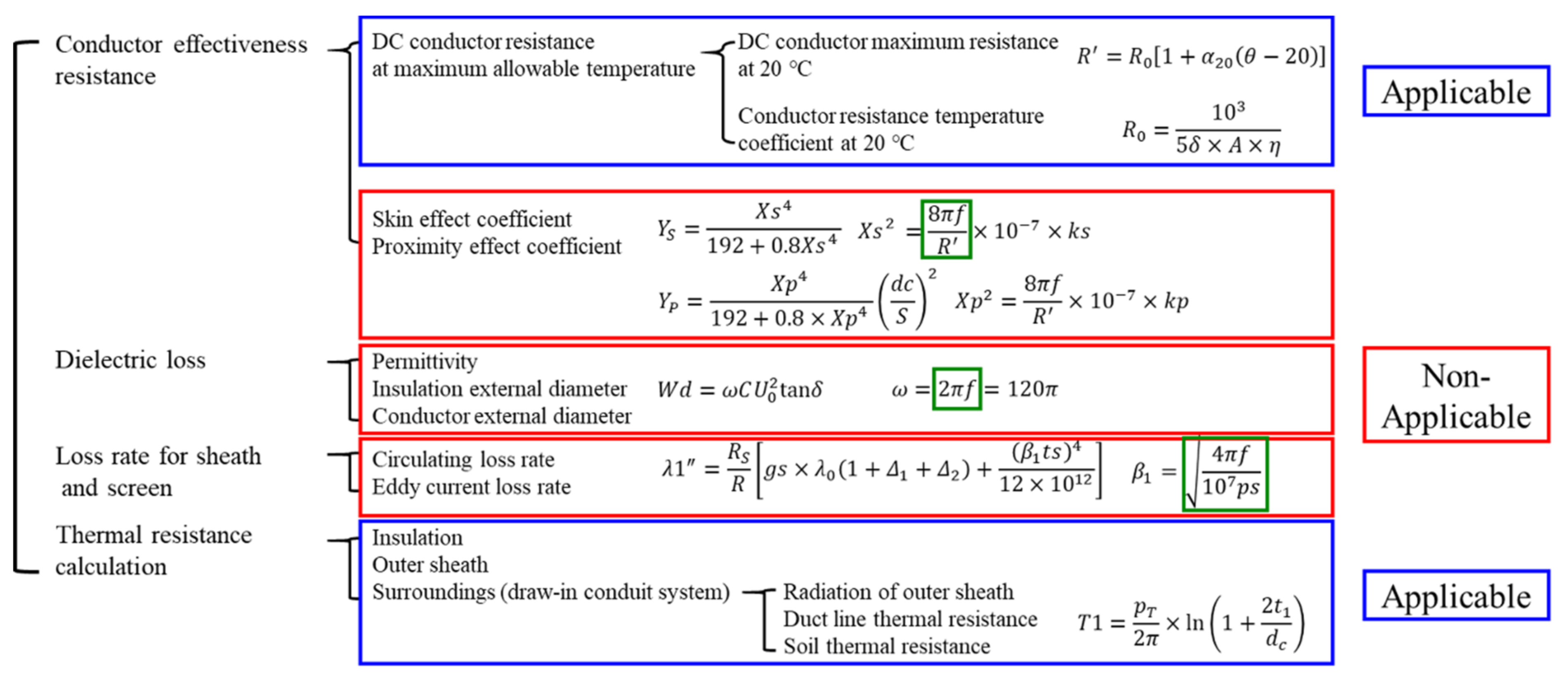
2.2. HVDC Cable Allowable Current

In Figure 1, each factor applied to the calculation of the allowable current of the AC cable is classified according to the presence or absence of frequency. To calculate the DC allowable current basic formula, it can be arranged as in Equation (2) if the factor generated by frequency is removed.
I = Δ θ R T 1 + R ( T 3 + T 4 )   [ A ]
Equation (2) is a formula organized by removing the frequency factor from Equation (1), and it is commonly presented in IEC 60287-1-1 [12] (DC below 30 kV) and Reference [13]. However, as confirmed in the reference material, the formula considers only the major factor ignoring the waterproof tape and air gap of the cable, and to accurately calculate the allowable current, such a minor factor must be applied. Therefore, the formula considering the variables can be summarized as follows.
I = Δ θ R T 1 + R ( T 2 + T 3 + T 4 )   [ A ]
where:
T2: Thermal resistance of waterproof tape and air gap (W/(m·K)).
Sometimes, even if the allowable current value is calculated by considering only the major factor, the allowable current margin of the cable may be sufficiently covered. However, as it is necessary to calculate the allowable current considering all factors in HVDC cables, this paper conducted a comparative analysis of the allowable current calculation for Equation (2) considering only the major factor and for Equation (3) considering the minor factor.

2.2.1. Maximum Resistance of DC Conductor (R)

The characteristics of the AC cable conductor are that it forms a sector strand after compressing a rounded strand in an AC cable, so the resistance value is calculated by considering the interleaving rate for each strand, the collective interception rate for the sector stranded strand, and the hardening factor. In the HVDC cable, as a bulk conductor is applied, the conductor resistance with respect to the cross-sectional area can be simply applied as shown in Equation (4).
R D C = ρ 20 L S ( 1 + α 20 ( θ 20 ) )
where:
ρ20: Resistivity at 20 °C;
α20: Temperature correction factor;
A: Cross-sectional area of conductor (mm2);
L: Length (m);
θ: Maximum allowable temperature of conductor.
R D C = 1.02 × 10 6 × ρ 20 S ( 1 + α 20 ( θ 20 ) )
where:
S: Cross-sectional area of conductor (mm2).
Equation (4) is a commonly used formula for calculating DC resistance according to the cross-sectional area and length of a conductor. However, in the case of that formula, it is applicable only when the cross-sectional area of the conductor is ideally configured. Therefore, as shown in Equation (5), we applied a correction factor of 2% in consideration of a slight error caused by the cross-sectional area, and it was applied in references [14,15,16].
  • Resistivity (ρ) and temperature correction factor (α) of conductor.
The resistivity and temperature correction factor of the conductor are the most important factors in determining the maximum allowable DC resistance, and copper and aluminum are typically used as cable conductors. In this paper, as shown in Equations (6) and (7), the temperature correction coefficients suggested in IEC 60228 [17] and IEC 60287-1-1 [13] were used as the formula.
k t , c u = 254.5 234.5 + t = 1 1 + 0.00393 ( t 20 )
k t , A l = 248 228 + t = 1 1 + 0.00403 ( t 20 )
where:
t: Maximum allowable temperature of the conductor.
Equations (6) and (7) are correction coefficients according to the temperature change of each copper conductor and aluminum conductor, and the temperature correction coefficient differs according to the amount of change based on 20 °C. According to the difference in the material properties, the standard of the resistance constant value can be applied differently.
Table 1 shows the resistivity and temperature correction factor according to the copper and aluminum conductors with the values presented in IEC 60287-1-1. The material standards for copper conductors were calculated based on the IEC 60028 standard, and the aluminum conductor material standards were carried out with reference to the IEC 60889 standards.
  • Cross-sectional area (copper, aluminum).
In addition to the resistivity of the conductor and the temperature correction factor, the cross-sectional area of the conductor acts as an important factor in determining the maximum resistance of the conductor. For comparison of conductor resistance according to conductor cross-sectional area, the DC resistance calculation formula of Equations (4) and (5) and the resistivity and temperature correction factor of Table 1 were applied and compared as follows.
Table 2 shows the results obtained by applying the resistivity of copper and aluminum to Equations (4) and (5) according to the cross-sectional area. The result value of Equation (5) was derived 2% higher than Equation (4), and as it is close to the result value considering the actual conductor, the DC conductor resistance value was calculated based on Equation (5) in this paper.

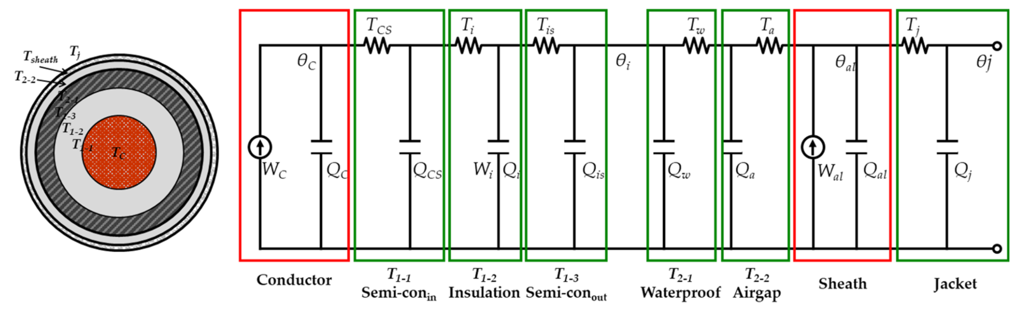
2.2.2. Thermal Resistance According to the Thermal Gradient

When current flows through the conductor of the cable, heat is generated by the resistance component. Unlike the heat dissipation of overhead transmission lines exposed to air, in the case of cables, as the thermal conductivity of the insulator is low, it is difficult to dissipate heat to the outside. The conductor is overheated by the accumulated heat, a vicious cycle of higher heat is generated due to the increased resistance of the conductor, and the continuous accumulation of heat causes insulation deterioration and voltage drop. Therefore, it is necessary to calculate the cable transmission capacity to guarantee the life of the cable and the stable operation of the power system. The maximum allowable current is determined by the maximum allowable temperature of the conductor (allowable temperature of insulator) of the cable.
The thermal gradient of the cable is divided into two components: heat generation and heat loss. Important factors in heat loss depend on several factors such as the surrounding medium (air or soil), the composition of the surrounding soil, moisture content, ambient temperature, and wind conditions. Heat is transferred through the cable and its surroundings in several ways, resulting in heat loss.
In Figure 2, the temperature gradient inside the cable is expressed as an equivalent circuit, and the physical property of storing or shielding heat according to each part of the cable is called thermal resistance and can be expressed as heat generation and heat loss. Heat generation is also divided into internal and external heat generation, and internal heat generation is heat generation due to eddy current in the heating metal sheath of the conductor. These heat generation and heat loss are balanced by the law of conservation of energy [12].
  • Thermal resistance of the insulator (T1).
The thermal resistance of the cable insulator is determined by the material of the insulator and the inner and outer semiconducting layers. Although the electrical characteristics inside the cable are different, in terms of allowable current, it is determined by the unit thermal resistance. If each structure has different thermal resistances, each thermal resistance must be calculated separately.
In the IEC 60287-2-1 standard, 3.5 (W/(m·K)) for XLPE and 6.0 (W/(m·K)) for MI-PPLP insulating materials are applied as thermal resistance values for each insulating material. In general, polyethylene (PE)-based materials are used for the inner and outer semiconducting layers. If the material of the cable insulator is XLPE, the thermal resistances of the inner and outer semiconducting layers and the insulator are the same, so it is possible to analyze it as one structure. However, in the case of a cable such as MI-PPLP, the thermal resistance of the insulator and the inner and outer semiconducting layers are different, so it is necessary to calculate and add them up according to the structural characteristics of each. Therefore, in this paper, the formulas are summarized according to the case where the thermal resistance is the same or different, and it is as follows.
  • The case of specific thermal resistance is the same (Ex. XLPE cable).
T 1 = ρ T 2 π × ln ( D 0 D i )   [ W / ( K m ) ]
where:
ρT: Insulator intrinsic thermal resistance (W/(m·K));
D0: Outer diameter of outer semiconducting layer (mm);
Di: Conductor outer diameter (mm).
Equation (8) is the insulator thermal resistance formula in Reference [12], and as the thermal resistances of the inner/outer semiconducting layer and the insulator (XLPE) are the same in this document, it was calculated as one structure. Therefore, if the thermal resistance is the same, it is obtained through the above formula.
2.
The case of thermal resistance is not the same (Ex. MI-PPLP cable).
If the specific thermal resistances of the inner/outer semiconducting layer and the insulator are not the same, it is necessary to analyze each structure instead of analyzing it as a single structure to calculate the allowable current. The insulation thermal resistance formula of IEC 60287 was applied and applied to each structure. After calculating the cross-sectional area of the corresponding cable structure, the thermal resistance for the cross-sectional area is calculated by applying the specific thermal resistance. The resulting formula is as follows.
T 1 = ( T 1 1 + T 1 2 + T 1 3 )
T 1 1 = p T 1 1 2 π × ln ( 1 + 2 ( t 1 1 ) d c 1 )   [ W / ( K m ) ]
where:
T1-1: Thermal resistance of the inner semiconducting layer (W/(m·K));
ρT1-1: Inner semiconducting layer (PE) intrinsic thermal resistance (W/(m·K));
t1-1: Inner semiconducting layer thickness (mm);
dc-1: Conductor outer diameter (mm).
  • Thermal resistance of waterproof tape and air gap (T2).
In the case of an actual cable, there are semiconductive waterproof tape and an air gap between the insulator and the metal sheath. The IEC 60287 standard does not consider these waterproof tapes and air gaps, because they have a smaller thickness than other structures and have lesser effects on the allowable current. However, the thermal resistances of the waterproof tape (6 W/(m·K)) and the air gap (34 W/(m·K)) are larger than those of the insulator and the outer shell. This increase in thermal resistance affects the calculation of allowable current and must be considered for thermal resistance analysis and allowable current calculation according to the accurate thermal gradient.
In addition, in the case of the smooth metal sheath used for KEPCO ultra-high-voltage cables in Korea, under ideal conditions, the waterproof tape and the metal sheath are perfectly in close contact, so there is little space occupied by air gaps. However, in the case of the corrugated metal sheath, as the space between the waterproof tapes is large and composed of voids, the effect of the voids is relatively increased compared to the smooth type of metal sheath. Therefore, to calculate the thermal resistance of waterproof tapes and air gaps according to the shape of the metal sheath, it was classified according to each condition.
  • Thermal resistance of the metal sheath (T3).
  • Types of metal sheath.
The material of the metal sheath differs depending on the cable laying conditions. In the case of direct and conduit type installation, a large amount of force is received between the cable sheath and the ground due to a strong external force during cable installation. There is a high possibility that physical damage to the jacket occurs due to such friction, and therefore, PE, which has physically strong characteristics, is applied as a metal sheath. In the case of tunnels-type installation, PVC with good flame retardancy according to fire vulnerability is applied because there is less physical damage compared to direct laying or conduit type. The thermal resistances for each insulating material of PVC and PE applied in this paper were 6.0 W/(m·K) and 3.5 W/(m·K), respectively, based on the IEC 60287-2-1 standard.
2.
Structural features.
To calculate the thermal resistance of the metal sheath, the structural characteristics must be considered in detail, and it is classified into a corrugated type and a smooth type. In the case of the corrugated metal sheath, the thickness of the corrosion protection layer is different depending on the cable position because the corrosion protection layer is applied along the curved surface of the metal sheath. Therefore, IEC 60287-2-1 suggests the following as a factor to be considered according to the structural characteristics of the metal sheath.
  • Thermal resistance of surrounding environment (T4).
In the case of a cable buried in the soil, there are many variables to be considered, such as the moisture content of the soil and the depth of the soil. In particular, consideration must be given to the depth of the soil, which accounts for the largest part in determining the thermal resistance to the surrounding environment, and the thermal resistance must be calculated accordingly. The thermal resistance to the surrounding environment is directly affected by the cable installation environment, and whether the metal sheath of the cable is in direct contact with the soil plays an important role in calculating the thermal resistance. In the case of soil thermal resistance of the AC cable, various techniques have been developed for the application of allowable current [18], and in the next section, we understand the principle of soil thermal resistance calculation in direct laying and a draw-in conduit system, and each single cable and multiple cable based on the calculation formula considering load, important factors for HVDC cable application, were analyzed.
  • Thermal resistance according to soil depth when installing single cables.
The application of ambient thermal resistance of direct burial laying and a draw-in conduit system can be applied based on the theory of cable cross-projection on the surface-atmosphere, as shown in Figure 3 below [19]. As the distance between the virtual cable and the actual cable is doubled based on the installation depth, it can be arranged as in Equation (11).
C = 2 π ε 0 ln 2 h a
Substituting the heat capacity C for RC = ρε, we obtain:
R = ρ ε C = ρ ε × ln ( 2 h / a ) 2 π ε = ρ 2 π ln ( 2 h / a )
If ρ is replaced with the soil intrinsic thermal resistance and applied, the soil thermal resistance formula can be obtained when a single cable is laid in the soil.
R = p T 2 π ln ( 2 h a )   [ W / ( K m ) ]
Through the derived formula, it can be confirmed that the thermal resistance increases with the burial depth. This increase in thermal resistance reduces the continuous allowable current, and the continuous allowable current decreases according to the burial depth.
2.
Thermal resistance according to soil depth when installing multiple cables.
However, in the case of an actual cable, a multi-line cable, not a single line, is laid in the same or adjacent locations. Therefore, it is necessary to calculate the soil thermal resistance for such cable laying, and the analysis according to the load factor of the cable should also be considered. These research results were compared with the Korea Electric Power Corporation standard DS 6210, and the corresponding thermal resistance calculation method was considered for DC [13].
T 4 = ρ T 2 π ln [ ( U + U 2 1 ) ( d p 1 d p 1 ) ( d p 1 d p 1 ) ( d p 1 d p 1 ) ( d p 1 d p 1 ) ]   [ W / ( K m ) ]
U = 2 L D e
Equation (14) is defined in IEC 60287-2-1 as a formula considering the effect of the mutual distance between cables. It was confirmed that it is composed in the same form as the thermal resistance formula applied in DS-6210, the current domestic KEPCO allowable current standard. dpq and dpq′ project a virtual cable up to the surface of the ground centered on the installed cable, and then apply the mutual thermal effect to the thermal resistance analysis based on the distance between the cables and the relative position of the projected cables.
3.
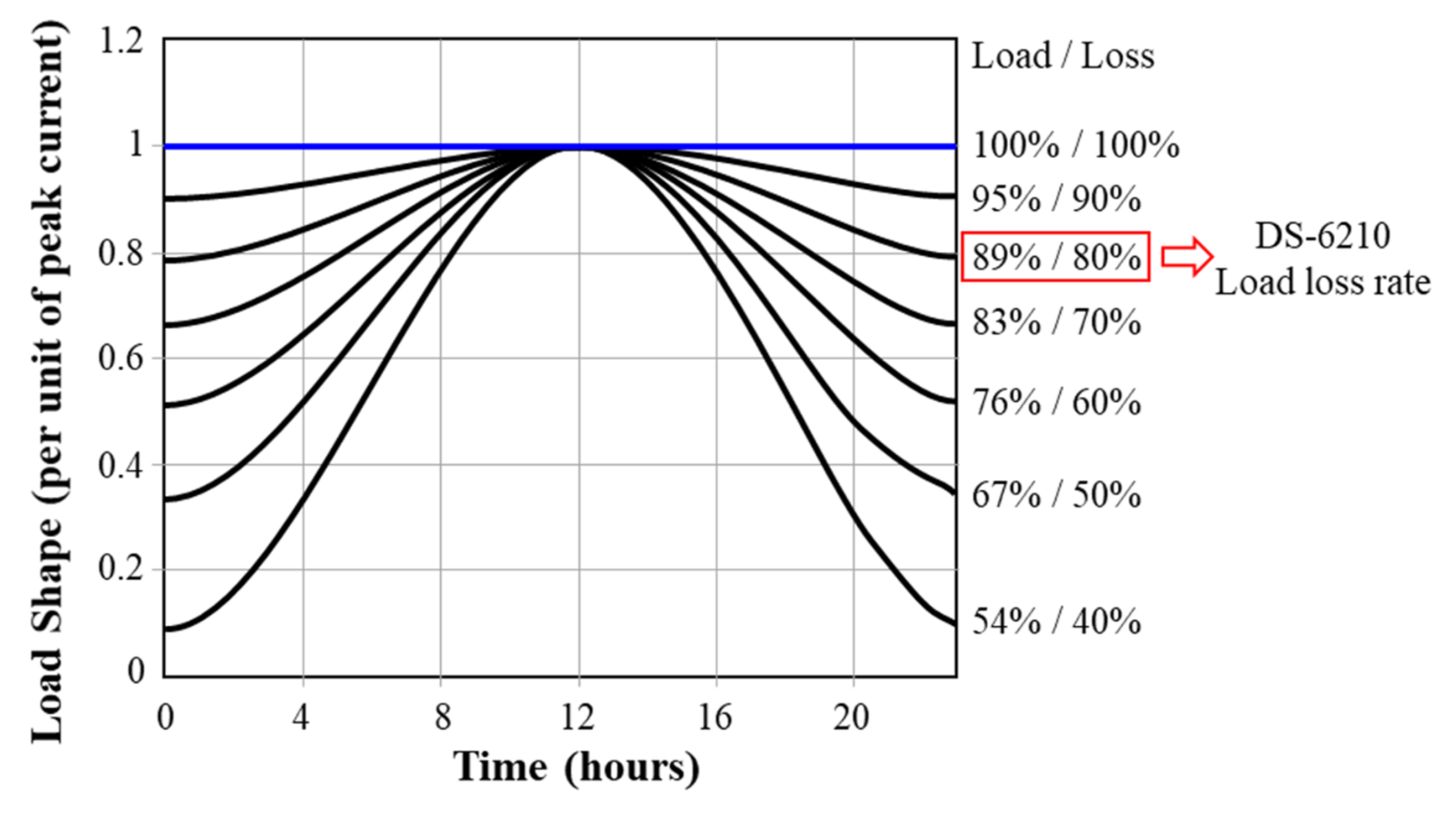
Thermal resistance according to load change conditions.
In the case of soil thermal resistance of IEC 60287-2-1, the load was calculated with 100% operating conditions. However, under these load operating conditions, the thermal superposition of the soil around the cable occurs [14]. Due to this thermal overlap phenomenon, the actual soil thermal resistance value is calculated to be higher than the calculated value. Therefore, variables for these loads must be considered. Figure 4 is a graph showing the load and loss ratio. In the design standard DS-6210 of Korea Electric Power Corporation (KEPCO, Naju, Korea), 80% of the load loss rate is applied.
Any point where the heat transfer of the soil part due to the soil heat overlap is reduced is an important factor in the estimation of the soil thermal resistance. When heat overlap occurs, heat transfer to the soil occurs at the point of overlap rather than heat transfer to the cable sheath-soil. Therefore, Neher/McGrath defined the distance exerted by thermal overlap assuming a sinusoidal shape in which a 24 h load cycle repeats a constant increase and decrease. The diameter is determined by the thermal diffusivity of the soil and was defined as 210 mm regardless of other conditions. It can be defined by Equation (16) by considering the effect of soil heat overlap and loading conditions and depth of installation [18].
T 4 = n 2 π [ ρ F i l l ( ln ( D x D e ) + L F ( ln ( 2 L + 4 L 2 D x 2 D x ) + ln ( F ) ) ]
4.
Calculation of thermal resistance in direct burial laying.
The direct burial laying is characterized by direct contact between the cable sheath and the soil. Cables with backfill should also be considered, and these considerations can be summarized as follows, and the thermal resistance (T43′) of the backfill material can be obtained by referring to the specification [18].
T 4 = T 43 + T 43

3. HVDC Cable Continuous Allowable Current Simulation Conditions

There are various parameters in addition to the above-mentioned variables in calculating the allowable current. In particular, the moisture content and the thermal resistance value of the soil have various environmental variables, from the location of the installation to a dry area from a high-moisture-content area such as a coastal area. In addition, the allowable current is changed by the relative separation distance and arrangement between each cable.
In this paper, assuming a specific cable system and conditions, the effectiveness of the allowable current calculation tool was verified. The simulated cable system is a three-phase cable system consisting of +500 kV, −500 kV, and a metallic return. A metallic return is not normally applied as a heat source (heat generation), because there is no load. As the thermal influence varies according to the separation distance between cables, the relative separation distance between each phase is changed according to the arrangement of the metallic return that does not exist as such a heat source. When installing multiple lines in one space at the same time, not only is it important between each phase, but the relative distance between different lines is also important. Even in such a multi-line installation, the allowable current changes according to the arrangement of the metallic return. Therefore, the installation condition was considered using the continuous allowable current of the HVDC cable, and the following cases were selected to compare the distance and influence between cables.

3.1. Cable System Modeling and Soil Temperature Conditions

3.1.1. Cable Specifications and Soil Conditions

Figure 5 shows the cable structure and model data applied in the calculation of the continuous allowable current. For the cable model, MI-PPLP 2115 mm2 was applied, and the metal sheath was applied. The continuous allowable current was compared and analyzed according to direct burial laying, temperature conditions, separation distance, and cable arrangement.
  • Soil thermal resistance.
Soil thermal resistance and temperature change, which are among the important factors in obtaining continuous allowable current, change according to season and precipitation. Therefore, the actual measured value was applied with weather reference, which measured the characteristics according to the actual soil change.
Table 3 presents the thermal resistance of the soil according to the moisture content, and it can be applied to the republic of Korea environment with significant seasonal differences in precipitation. In this paper, the allowable current was calculated by applying the thermal resistance of weathered soil B and 5% moisture-content soil. In addition, in consideration of seasonal temperature change, simulations were performed by dividing summer and winter, respectively, and 29 °C in summer and 3 °C in winter were applied.

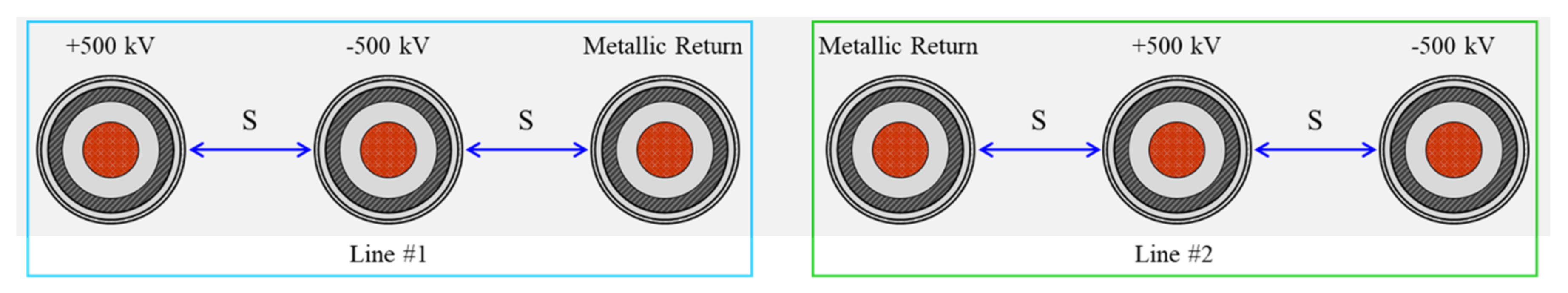
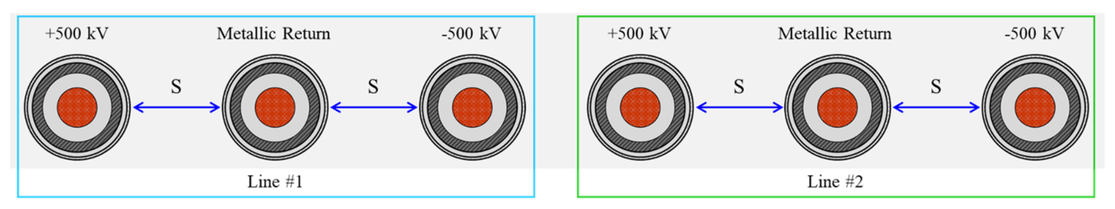
3.1.2. Cable Arrangement Conditions

There is a difference in the thermal effect between each cable arrangement. The allowable current is changed according to the difference in the thermal effect. In AC cables, mutual inductive components have a great influence on cable arrangement, but in DC cables, they are analyzed only as simple heat sources, so it can be summarized as the following case. In addition, in the case of the metallic return, no load occurs during normal operation, so in this paper, only +500 kV and −500 kV lines were assumed and analyzed as heat sources.
For the cable arrangement to be considered in the direct burial laying, a horizontal arrangement was applied, and it was classified into two cases according to the relative position of the metallic return.
Case 1-1 in Figure 6 is a model in which the distance between lines is increased by arranging the metallic return between each line. As a result, this is a case in which the factor of the heat effect generated in the 1st line on the 2nd line is reduced as much as possible.
Figure 7 is a case in which the thermal effect generated in each line is minimized by arranging the metallic return in the middle of each line.

3.1.3. Calculation Tool for Applying Continuous Allowable Current for HVDC Underground Transmission Cable

To directly compare the thermal resistance (T4) of the surrounding environment, which changes according to each installation method, and the major and minor factors, an allowable current calculation tool was developed using Excel. The calculation tool considered structural conditions (smooth and corrugated type), installation conditions (direct burial laying), and temperature conditions (seasonal) for calculating allowable current. In particular, the allowable current calculation was performed for the direct burial method, which is most applied as the HVDC cable burial method. It was also constructed based on the HVDC cable allowable current calculation formula.

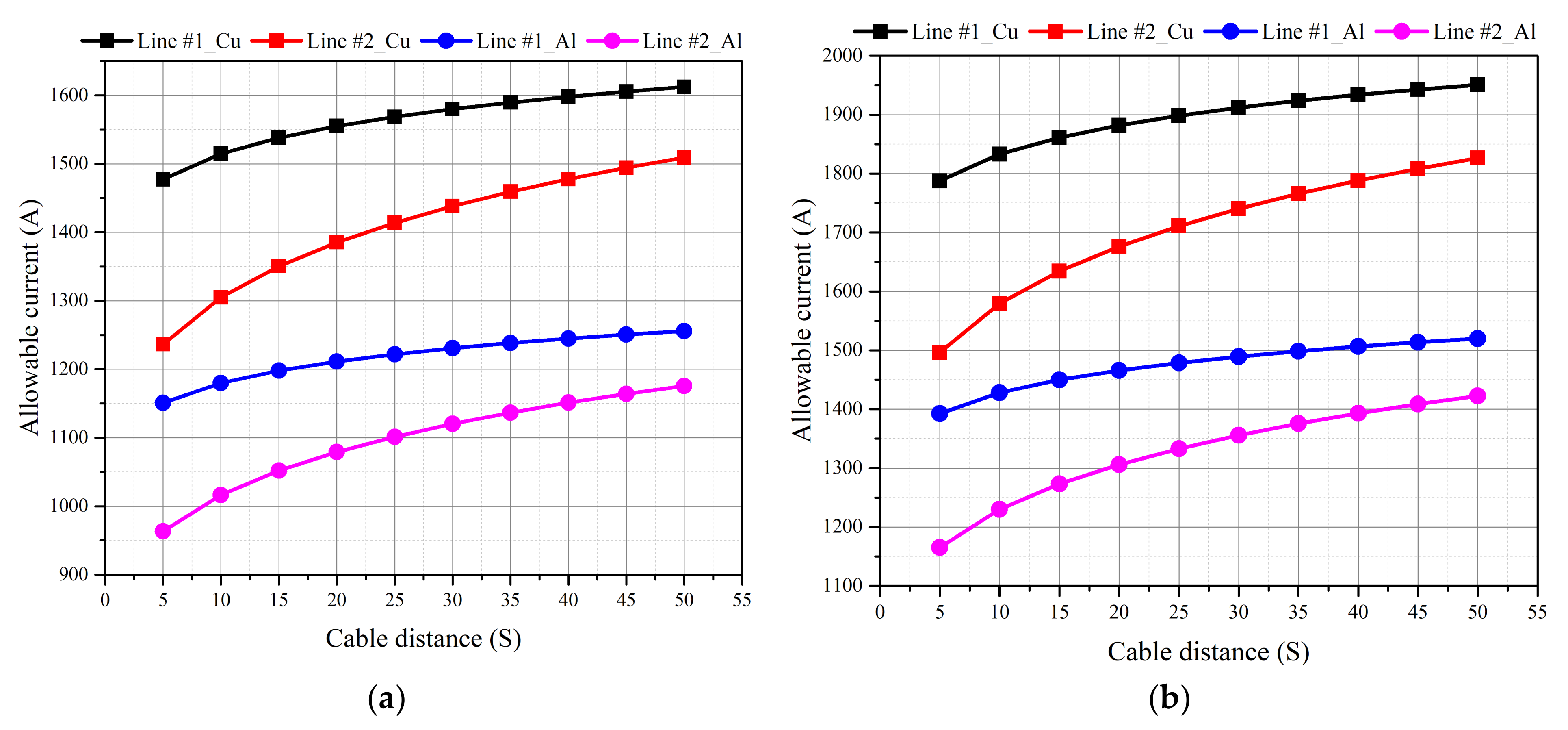
4. Comparative Analysis of Continuous Allowable Current of HVDC Underground Transmission Cable

4.1. Calculation of Continuous Allowable Current Considering Major Factor

The major factor is applied as an important variable in general allowable current analysis and is the most important factor in determining the allowable current. Variables applied are conductors, insulators, metal sheath, and the surrounding environment.

Calculation of Allowable Current for Direct Burial Laying

The continuous allowable current was calculated according to the separation distance between the cables according to the cable arrangement, and the results are shown in Figure 8 and Figure 9 below. The calculations were made separately for the case of lines of cable 1 and 2 and the case where the conductors were copper and aluminum, respectively, and the continuous allowable current was analyzed according to the change in season. In Figure 8a, when the seasonal condition is a summer temperature condition and compared with Figure 8b, which is a winter condition, it was confirmed that a high allowable current can be transmitted in winter when the ambient temperature is low compared to summer. In addition, as the separation distance between each cable increases, the thermal influence between cables decreases, so the allowable current gradually increases, and the difference in allowable current between the 1st and 2nd lines is reduced. Therefore, when the separation distance is more than 1 m, it can be inferred that the influence between cables is greatly reduced and there is no difference in allowable current.
Figure 10 shows results comparing and analyzing each case in the direct burial laying. The allowable current of Case 1-2 increased by 2.4% compared to Case 1-1. In addition, in the result of comparing 2 lines under the same conditions, the allowable current of Case 1-2 increased by 3.0% compared to Case 1-1. It can be confirmed that the model that can increase the distance between each cable phase is more advantageous in terms of allowable current because the relative thermal influence decreases compared to the model that can increase the distance between each line.

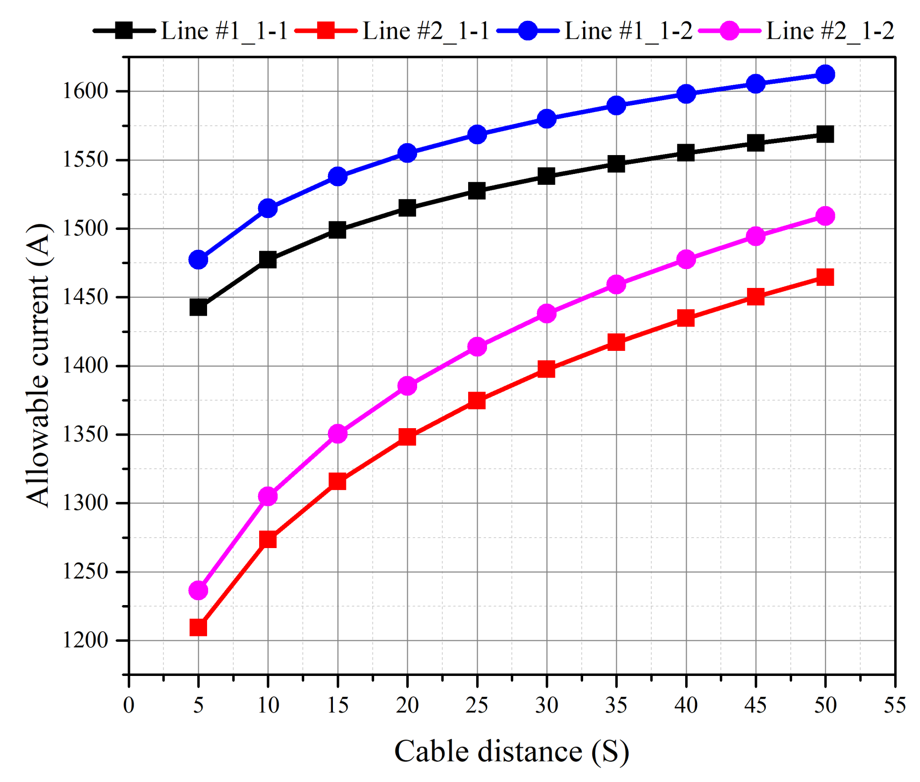
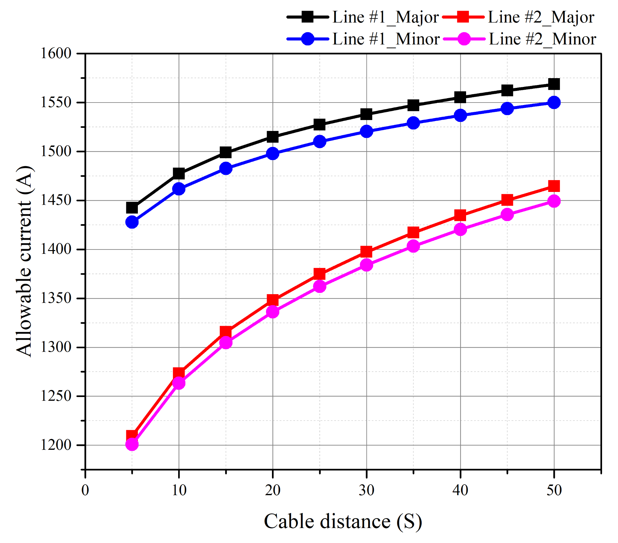
4.2. Continuous Allowable Current Calculation Considering Minor and Major Factor

The minor factor refers to the classification of a few factors that affect the allowable current, as well as the factors presented in IEC 60287. These include an inner semiconducting layer, an outer semiconducting layer, waterproof tape, and airgaps. By applying these factors, it is possible to obtain detailed and accurate allowable current for the cable. These factors affect the denominator of the formula constituting the allowable current of the following formula, respectively, Equation (18) is the formula to which the major factor is applied, and Equation (19) is the formula to which the minor factor is applied. The method for this application method is introduced in Reference [12], and by applying these factors, a comparative analysis was conducted for each case according to the installation method and the separation distance.
R T 1 + R ( T 3 + T 4 )
R T 1 + R ( T 2 + T 3 + T 4 )

Comparison of Allowable Current Results

The allowable current was calculated according to each case, and the results are as follows. As a result of the analysis by applying the minor factor, the installation method of Case 1-2 can transmit the highest allowable current in the direct burial laying as when only the major factor was analyzed. It can be confirmed that the arrangement that increases the separation distance between cables decreases the thermal influence compared to the arrangement that increases the separation distance between lines, and through this, the allowable current rises.
As a result of comparing the major and minor factors in Figure 11, it was confirmed that the allowable current of Line #1 (single line) to which only the major factor is applied is 1.2% higher than the allowable current including the minor factor. Moreover, as a result of comparing the allowable current when installing two lines under the same conditions, it was also confirmed that the major factor can have 1.1% higher allowable current. The reason for this is that the overall thermal resistance increased because the internal and external semiconducting layers and waterproof tape, which were ignored or omitted in the minor factor, were considered.

5. Conclusions

In this paper, the continuous allowable current calculation tool was established by classifying and formulating the key factors for calculating the allowable current of a direct burial laying HVDC underground cable based on the existing AC cable allowable current calculation formula. To verify the consistency of the calculation tool, the allowable current calculation simulation was performed by dividing the major factor (T1 insulation (not considering semiconducting layer), T3 metal sheath, and T4 surroundings) and minor factor (T1 insulation (considering semiconducting layer), T2 waterproof tape and airgaps, T3 metal sheath, and T4 surroundings) according to the variables to be considered. The conclusions drawn from this study are summarized as follows.
(1)
Core factors affecting the continuous allowable current value of direct burial laying HVDC underground cables can be divided into internal factors (cable specifications (conductor thermal resistance, T1, T2, T3)) and external factors (T4). It was confirmed that the cable conductor-specific thermal resistance has the greatest influence among internal factors due to the nature of direct current without an alternating magnetic field, and the surrounding environmental condition (T4) in which the cable is buried is an important key factor.
(2)
A simulation was performed to calculate the allowable current of the direct burial laying HVDC underground cable by season and laying condition, and it was confirmed that the allowable current in summer and winter differed greatly, and that the DC cable was greatly affected by the surrounding environment. In addition, in order to find the optimal laying arrangement of HVDC underground cables, various arrangement conditions were assumed, and a comparative analysis was conducted, and it was confirmed that a difference in allowable current value of up to 3% occurred depending on the laying method of the same cable in the direct laying method.
(3)
To compare the effects of internal factors on the allowable current of HVDC underground cables, referring to the technical documentation, the allowable current calculation simulation was conducted by dividing the allowable current into major and minor factors. When only the major factor was considered, the allowable current value was 1.2% further increased. Therefore, the effect of waterproof tape and airgaps included in the minor factor is not large, and occasionally, the continuous allowable current can be calculated by considering only the major factor.
As a result, by analyzing various standards and technical documents, a formula for calculating the continuous allowable current of a quantitative direct burial laying HVDC underground cable was established. Moreover, the allowable current characteristics of the HVDC underground cable were analyzed through continuous allowable current simulation using a calculation tool. As a future study, it is possible to establish the formula for calculating the continuous allowable current of the draw-in conduit and tunnels method and, furthermore, the HVDC submarine cable.

Author Contributions

Conceptualization, K.-h.P. and B.-w.L.; methodology, K.-h.P.; software, K.-h.P. and I.K.; validation, K.-h.P. and B.-w.L.; formal analysis, K.-h.P.; investigation, K.-h.P. and I.K.; resources, K.-h.P. and I.K.; data curation, K.-h.P.; writing—original draft preparation, K.-h.P.; writing—review and editing, B.-w.L. and I.K.; visualization, K.-h.P.; supervision, B.-w.L. All authors have read and agreed to the published version of the manuscript.

Funding

This research received no external funding.

Institutional Review Board Statement

Not applicable.

Informed Consent Statement

Not applicable.

Data Availability Statement

Not applicable.

Conflicts of Interest

The authors declare no conflict of interest.

References

  1. Song, F.; Wang, Y.; Zhao, L.; Liang, L.; Tao, W. Study on thermal load capacity of transmission line based on IEEE standard. J. Inf. Process. Syst. 2019, 15, 464–477. [Google Scholar]
  2. Dubitsky, S.; Greshnyakov, G.; Korovkin, N. Comparison of finite element analysis to IEC-60287 for predicting underground cable ampacity. In Proceedings of the 2016 IEEE International Energy Conference (ENERGYCON), Leuven, Belgium, 4–8 April 2016. [Google Scholar]
  3. Slegers, J. Transmission Line Loading: Sag Calculations and High-Temperature Conductor Technologies; Iowa State University: Ames, IA, USA, 2011; pp. 1–24. [Google Scholar]
  4. Dong, X.; Wang, C.; Liang, J.; Han, X.; Zhang, F.; Sun, H.; Wang, M.; Ren, J. Calculation of power transfer limit considering electro-thermal coupling of overhead transmission line. IEEE Trans. Power Syst. 2014, 29, 1503–1511. [Google Scholar] [CrossRef]
  5. Beryozkina, S.; Sauhats, A.; Vanzovichs, E. Climate conditions impact on the permissible load current of the transmission line. In Proceedings of the 2011 IEEE Trondheim PowerTech, Trondheim, Norway, 13–23 June 2011. [Google Scholar]
  6. Kim, D.-M.; Kim, J.-O. Prediction of transmission-line rating based on thermal overload probability using weather models. Eur. Trans. Electr. Power 2010, 20, 534–544. [Google Scholar] [CrossRef]
  7. Salata, F.; Nardecchia, F.; Vollaro, A.D.L.; Gugliermetti, F. Underground electric cables a correct evaluation of the soil thermal resistance. Appl. Therm. Eng. 2015, 78, 268–277. [Google Scholar] [CrossRef]
  8. Xu, X.; Yuan, Q.; Sun, X.; Hu, D.; Wang, J. Simulation analysis of carrying capacity of tunnel cable in different laying ways. Int. J. Heat Mass Transf. 2019, 130, 455–459. [Google Scholar] [CrossRef]
  9. Brakelmann, H.; Anders, G.J. Current rating considerations in designing HVDC cable installations. IEEE Trans. Power Deliv. 2018, 33, 2315–2323. [Google Scholar] [CrossRef]
  10. Mardiana, R. Parameters affecting the ampacity of HVDC submarine power cables. In Proceedings of the 2011 2nd International Conference on Electric Power and Energy Conversion Systems (EPECS), Sharjah, United Arab Emirates, 15–17 November 2011. [Google Scholar]
  11. IEC 60287-2-1 Ed.2. Electrical Cables—Calculation of the Current Rating—Part 2-1 Thermal Resistance—Calculation of Thermal Resistance; IEC: Geneva, Switzerland, 2015. [Google Scholar]
  12. Yang, L.; Qiu, W.; Huang, J.; Hao, Y.; Fu, M.; Hou, S.; Li, L. Comparison of Conductor-Temperature Calculations Based on Different Radial-Position-Temperature Detections for High-Voltage Power Cable. Energies 2018, 11, 117. [Google Scholar] [CrossRef] [Green Version]
  13. IEC 60287-1-1 Ed.2.1. Electrical Cables—Calculation of the Current Rating—Part 1-1 Current Rating Equations (100% Load Factor) and Calculation of Losses—General; IEC: Geneva, Switzerland, 2014. [Google Scholar]
  14. Almallah, M.R. Ampacity of HV Multi-Insulation Cables at Different Cooling Methods: HVAC and HVDC Power Cables; Scholars’ Press: Atlanta, GA, USA, 2016. [Google Scholar]
  15. Anders, G.J.; Institute of Electrical and Electronics Engineers. Rating of Electric Power Cables in Unfavorable Thermal Environment; Wiley: New York, NY, USA, 2005. [Google Scholar]
  16. Graneau, P. Underground Power Transmission; U.S. Department of Energy Office of Scientific and Technical Information: Oak Ridge, TN, USA, 1979.
  17. IEC 60228 Ed.3. Conductors of Insulated Cables; IEC: Geneva, Switzerland, 2004. [Google Scholar]
  18. IEC 60287-2-3 Ed.1. Electric Cables—Calculation of the Current Rating—Part 2-3: Thermal Resistance—Cables Installed in Ventilated Tunnels; IEC: Geneva, Switzerland, 2017. [Google Scholar]
  19. Worzyk, T. Submarine Power Cables: Design, Installation, Repair, Environmental Aspects; Springer Science & Business Media: Berlin/Heidelberg, Germany, 2009. [Google Scholar]
Figure 1. AC allowable current calculation factor.
Energies 14 06431 g001
Figure 2. Thermal gradient in HVDC cables.
Energies 14 06431 g002
Figure 3. Cable–surface (soil) thermal interaction.
Energies 14 06431 g003
Figure 4. Variation in load and loss rate.
Energies 14 06431 g004
Figure 5. Cable specifications for simulation.
Energies 14 06431 g005
Figure 6. Direct burial laying arrangement (Case 1-1).
Energies 14 06431 g006
Figure 7. Direct burial laying arrangement (Case 1-2).
Energies 14 06431 g007
Figure 8. Comparison of allowable current in summer (a) and winter (b) according to cable separation distance (Case 1-1).
Energies 14 06431 g008
Figure 9. Comparison of allowable current in summer (a) and winter (b) according to cable separation distance (Case 1-2).
Energies 14 06431 g009
Figure 10. Comparison of allowable current by condition of each case.
Energies 14 06431 g010
Figure 11. Comparison of major and minor factor allowable current.
Energies 14 06431 g011
Table 1. Resistivity (ρ20) and temperature correction factor (α20) according to conductor material.
Conductor MaterialsResistivity (ρ20)
at 20 °C (Ω∙m)
Temperature Correction
Factor (α20) at 20 °C (1/K)
Copper1.7241 × 10−83.93 × 10⁻³
Aluminum2.8264 × 10−84.03 × 10⁻³
Table 2. DC conductor resistance according to conductor material (at 20 °C).
Cross-Sectional Area (mm2)Copper (Ω/km)Aluminum (Ω/km)
Equation (1)Equation (2)Equation (1)Equation (2)
20008.621 × 10−38.793 × 10−31.413 × 10−21.441 × 10⁻²
21008.210 × 10−38.374 × 10−31.346 × 10−21.373 × 10⁻²
22007.837 × 10−37.994 × 10−31.285 × 10−21.310 × 10⁻²
23007.496 × 10−37.646 × 10−31.229 × 10−21.253 × 10⁻²
24007.184 × 10−37.327 × 10−31.178 × 10−21.201 × 10⁻²
25006.896 × 10−37.034 × 10−31.131 × 10−21.153 × 10⁻²
Table 3. Soil thermal resistance according to moisture content.
Moisture
Content
Weathered Soil A
(W/(m·K))
Weathered Soil A + Sand (W/(m·K))Weathered Soil B (W/(m·K))
5%0.97 0.94 1.09
10%0.58 0.58 0.55
15%0.52 0.46 0.52
Publisher’s Note: MDPI stays neutral with regard to jurisdictional claims in published maps and institutional affiliations.

