1. Introduction
The depletion of conventional hydrocarbon reserves is creating a need to develop hard-to-recover oil deposits, such as heavy- and high-viscosity oils or, in general, heavy-oil blends (HOB). The reserves of these types of oils are more than two times the reserves of traditional oil [
1]. As a rule, HOB is characterized by high viscosity and density, and increased content of various metals such as vanadium, nickel, gold, zinc, copper, etc. [
2,
3,
4]. It is necessary to take into account these properties of HOB when assessing their possible hazardous influence on the environment [
5]. Among the parameters describing the rheological properties of oil, in practice, parameters characterizing its structural properties are most often used [
6,
7].
Whereas production costs for heavy-oil extraction are usually higher than those for conventional oil, the introduction of enhanced oil-recovery techniques (e.g., steam-assisted gravity drainage, toe-to-heel air injection, etc.) leads to increased recovery rates and, consequently, to decreasing costs [
8].
These methods are needed to provide for flowability and sustainable production of heavy oil. Thus, various treatment techniques aimed at effecting rheological properties of high-viscosity or heavy oil are necessary for efficient production. Physical and chemical treatments considers several method to ensure efficient recovery of HOB [
9]. The thermal effect is a common way to provide stable hydrocarbon production, especially when considering complicated climate conditions with low temperatures of ambient air, such as the Arctic region [
10]. Many oil fields there are characterized by hard-to-recover reserves, such as heavy oil and high-viscosity oil. Another method of sustainable recovery is the application of pour point depressants and exposure of heavy hydrocarbons to ultrasonic fields, which can be considered more environmentally friendly than thermal methods [
11].
Issues of heavy-oil flow simulation are especially important. Though the main concerns are extraction, production, and transportation, modeling techniques ensure successful development. Each stage of oil production has its own peculiarities concerning flow simulation; thus, it is necessary to consider a specific technological process individually. The lifting of well fluids from the borehole bottom to the wellhead presents quite a challenge for flow simulation. Possible changes in the mode of well operation, such as stops and start-ups of the pumps, lead to changes in rheological characteristics of the fluid and, consequently, flow regimes that pose a danger for stable and efficient production [
12]. The specifics of non-Newtonian fluid flow simulations in annular medium, such as in the oil well, are needed to calculate possible changes in the pressure loss during transient processes, which should be noted during well operations or application of enhanced oil recovery techniques [
13].
Although the problem of investigating the properties of non-Newtonian fluids and their behavior during flow in the wellbore was considered in some works [
14,
15], the proper calculation of the rheological characteristics of heavy oils and HOBs and their corresponding flow simulation models during lifting in the well is still a challenge.
For example, the Yaregskoye field produces unique heavy high-viscosity oil, from which a significant amount of valuable and high-quality oils products and bitumen can be obtained [
16]. Heavy oil with a density of 964.4 kg/m
3 at 20 °C and a naphthenic-aromatic base is being produced at the Yaregskoye field. This oil is mixed with other oils from the northern fields of the Timan-Pechora oil and gas province and is transported further through the pipeline. Most of the oils from the northern fields are characterized by anomalous properties: high pour point and high viscosity. It should be noted that these indicators only increase every year (
Table 1), worsening the transport performance of the pumped oils, which leads to an increase in both economic and technological costs during the construction and operation of equipment necessary for pumping such oils [
17].
The Varandey sea terminal on the Pechora Sea coast in the Arctic was recently commissioned, specially designed to transport oil from the Timan-Pechora province. The northern route through the Barents Sea offers an alternative supply to both the European and American markets. It can be assumed that new opportunities will appear in the company’s logistics plans for Yarega oil, where it will be mixed with paraffinic oil from the Varandey field [
18].
Thus, the aim of this paper is to assess the physical, chemical, and specifically the rheological properties of heavy-oil blends and their influence on flow parameters during pumping through the oil-field pipelines. It should be noted that the oils under consideration are non-Newtonian anomalously viscous liquids, the interaction of which can cause a deterioration in the flow characteristics of the blend obtained from them. In this regard, the question arises of finding optimal solutions for influencing the oil flow in order to improve the physical, chemical, structural, and mechanical properties of the heavy hydrocarbons. The results of the conducted research can be used for subsequent selection of the most effective solution to improve the transport characteristics of the oils. For example, one of the promising solutions is the treatment by ultrasound [
19].
2. Materials and Methods
This work studied (as a case) the change in physical, chemical, and structural-mechanical properties (
Table 2) for 4 blends of Yarega and Varandey oils with concentrations of heavy Yarega oil in blends at 10, 15, 25, and 50%.
A rotary viscometer Rheotest RN4.1 was used to conduct experiments in the study of the oil’s rheological characteristics. Measurements were carried out in 0–600 rpm range of viscometer rotor speeds. Different rotation speeds of the rotational viscometer corresponded to different deformation rates of the fluid: from low speeds at the beginning of fluid motion to higher values during flow through the pipeline. Rheological parameters were determined using a viscoplastic and power-law solution model. A measuring system was necessary to study the rheological characteristics of substances with a viscosity of up to 100,000 mPa∙s. It consisted of a stationary measuring cup and a cylindrical rotor, which was placed in this cup. To study the behavior of liquids at different temperatures, thermostat and thermo-insulated vessels were used [
20].
2.1. Analytical Dependencies
In most cases, HOBs obey the law of a pseudoplastic fluid [
21]. To describe the HOB motion, a theoretical rheological model is proposed:
where
is frictional stress,
is structural internal strength stress, and
is dispersed flow viscosity stress.
Due to the thixotropy of the system, it can be assumed that and tend to zero with an increase in the velocity gradient and, therefore, will be described by an exponential dependence on the shear rate. When certain values of the velocity gradients are reached, HOBs move similarly to Newtonian fluid and its internal stresses is characterized only by viscous friction.
Frictional stress can be determined from the following equation:
where
is the coefficient of frictional stress;
is shear stress, Pa; and
is the shear–strain rate (shear rate), s
−1.
If we consider a short time interval
, then it can be assumed that the relative decrease in the internal stress will be proportional to the shear gradient, whereas
where
is the coefficient characterizing the internal strength of a structured flow.
For liquids similar to Newtonian ones, the dependence of shear stress on the velocity gradient [
22] has the following form:
where
is dynamic viscosity, Pa∙s. Substituting Equations (2)–(4) into Equation (1), we obtain the following:
Equation (5) reflects the dynamics of internal structural transformations in HOBs and makes it possible to determine the shear stresses depending on the velocity gradients. As a result of the analytical calculation, a polynomial function was obtained [
23]:
2.2. Methods of Numerical Modeling
It is necessary to create a model that is adequate for the experimental data, which will further allow for investigations of ways to reduce pressure losses during oil production, e.g., by changing the velocity and mode of oil pumping or by changing the diameter of the pipeline.
There are many models implemented in various software for defining the non-Newtonian behavior of a fluid. The working medium investigated can be both a viscous Newtonian fluid and a non-Newtonian viscoplastic fluid, the behavior of which is described by one of the three most common rheological models [
24,
25]. The effective viscosity can take different forms depending on the rheology of the working medium. In most cases, HOBs obey the law of a pseudoplastic fluid [
26]; therefore, a power-law model is used—the Ostwald–de Waele dependence:
where
is the yield stress at shear rate equal 0,
is the consistency index (a measure of the average viscosity of the fluid and proportional to the viscosity of the liquid), and
n is the Power Law index (a measure of the deviation of the fluid from Newtonian). For
n = 1, the liquid is Newtonian.
In the ANSYS software, the Ostwald–de Waele equation has the following form:
where
is the apparent (dynamic) viscosity, Pa∙s, and
is the normalizing time constant. Here, a non-Newtonian is a fluid for which the shear stress is not linearly proportional to the shear–strain rate (shear rate). For such fluids, the apparent viscosity is the ratio of shear stress to shear rate for a given shear rate.
To represent the experimental dependence, the Ostwald–de Waele equation was chosen. The generalized reduced gradient (GRG) method, proposed by Lasdon et al. [
27], was used for non-linear optimization [
28]. The coefficients
K,
, and
n were calculated so that there is minimum divergence with experimental data (
Figure 1):
If we simplify Equation (9) to the form
, assuming
= 1, then we can use a power-law approximation to fit the experimental function. As a result, the following equation was obtained:
The obtained approximation results describe the experimental function correctly. When setting the parameters for the Ostwald–de Waele model in ANSYS, both options (9) and (10) are suitable, while the simplified form of the power approximation showed better convergence.
Figure 2 shows how the oil viscosity decreases with increasing shear rate gradient, reaching its minimum value at a rate of about 6 s
−1. At higher values of the shear rate gradient, the oil under study can be considered a Newtonian fluid with a viscosity of 2.5 Pa·s.
2.3. Mathematical and Numerical Modeling
The mathematical model of a non-Newtonian fluid flow processes is a set of Navier–Stokes equations in the stress tensor component form, the continuity equation, the rheological equation of the medium, and the boundary conditions set in a cylindrical coordinate system [
29]. The equation of state for a non-Newtonian fluid is applicable to multiphase high-viscosity media, which, as mentioned above, is set in the form of an Ostwald–de Waele power law Equation (9) or a polynomial function Equation (6) as a custom expression.
The computational area is a section of an oil field pipeline designed to transport hydrocarbons from the wellhead to the treatment plant at the oil field. Often, these are pipelines with a diameter of up to 426 mm with an excess pressure of the medium up to 10 MPa. Under these conditions, the velocity of the HOB will be up to one meter per second.
To determine the hydrodynamic characteristics of the HOB influenced by the hydraulic resistance along the length of the pipeline and to compare the results for different HOBs flowing under different conditions, a numerical model was created. Its creation included several stages.
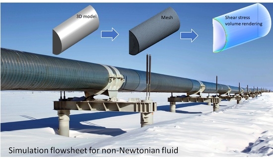
At the first stage, the modeling area was built, which included the construction of solid geometry and the creation of a mesh in ANSYS. The considered scheme of fluid flow in the pipeline is shown in
Figure 2. An axisymmetric section of the pipeline with an outer diameter of 299 mm and 3000 mm length was built in the CAD software.
The flow domain of the pipe was discretized using hexahedral elements oriented along the fluid flow for an axisymmetric channel (
Figure 3). Mesh refinement in the wall region was also implemented.
The input data for the constructed model is given in the
Table 3.
In turbulent flow, in most cases, values of shear rates are achieved that destroy the structure of the oil (for simulated oil—6 s
−1) and the viscosity becomes constant [
30]. Therefore, when studying the non-Newtonian behavior of oil, the main interest is the laminar flow regime, in which low shear rates exist and the oil actively manifests its anomalous properties.
From a practical point of view, modeling the flow of oil in a laminar regime is justified by the fact that, during oil production, a turbulent flow regime is first achieved in the pipeline or submersible pump and that, during lifting and transportation, heavy oil has time to structure, a flow core is formed, and particles move with almost the same velocity in a laminar mode.
Below, we consider a fully developed stationary flow of an incompressible fluid in a laminar regime through a channel of constant cross section. The rheology of the working medium is described by a generalized Newtonian model. In this model, the medium is considered a nonlinear viscous fluid. The notion of the effective viscosity of the fluid, which generally depends on the rate of the medium’s deformation, is introduced in the model. In this formulation, the laminar flow regime is described by Navier–Stokes equations:
where
is liquid density in kg/m
3;
is velocity vector; p is pressure, Pa; and
is the Del (nabla) operator. For the generalized Newtonian model, the viscous stress tensor τ is determined as follows:
where
S is the strain rate tensor. The components of the strain rate tensor
S have the following form:
The intensity of the strain rates for the medium is the second invariant of the strain rate tensor:
In (15), Sij corresponds to gradients of mean velocity and mean shear rate, which together contribute to the shear rate tensor.
3. Results
Figure 4 shows the experimental dependencies of the shear stress
in the HOB flow on shear rate
at different temperatures.
Heavy oils are highly plastic nonlinear viscous non-Newtonian fluids, the rheological properties of which are described by the well-known Shvedov–Bingham equation [
6]. However, in areas of low shear stresses, the dependence has a nonlinear form, which is not taken into account in the mentioned model. This region, which is difficult for modeling, is replaced by extrapolation of the straight-line part of the graph to zero shear rate, or other values of the parameters included in the Shvedov–Bingham model are calculated [
7,
8,
9].
As an example, let us present the analytical (6) dependence of the shear stress on the shear rate for low values of shear rate obtained for the experimental characteristics of HOB flow at a temperature of 20 °C (see
Figure 5).
Figure 5 shows that the experimental rheological data are in good agreement with the models in (6), (9) and (10) under the given boundary conditions when the initial fluid velocity is about 0.3–0.4 m/s.
The oil velocity values obtained in the simulation are plotted in
Figure 6. The velocity profiles obtained from the simulations are shown in
Figure 7. The presented profiles differ from the parabolic profiles of Newtonian fluid [
31]. In particular, it should be noted that
Figure 7 shows the velocity profiles for initial flow velocities of 1.5 and 1 m/s. These velocity profiles describe a mixed flow; however, calculations show that, even at high pressure gradients, a region of non-Newtonian flow remains near the center of the flow. In other words, during the flow of a non-Newtonian fluid with increasing velocity, the region of the non-Newtonian flow narrows, being localized to the center of the flow.
Before evaluating the effect of oil viscosity on other parameters, one needs to make sure that the obtained results are correct by taking the viscosity curve from the simulation model and by comparing it with the curve obtained by substituting various values of the simulated shear rate in Equation (12), which, in turn, represents an approximation to experimental data.
At first glance, it can be assumed that the viscosity decreases towards the center of the pipeline, where the velocity (
Figure 7) is higher, but in the case under consideration, the viscosity (
Figure 8) is a function of one variable: the shear rate. Additionally, with an increase in the shear rate
, the viscosity
µ decreases. However, the shear rate in the flow core is very low (
Figure 9) even for the location with the highest velocity (
Figure 6).
Another important characteristic to measure is the distribution of the pressure (
Figure 10). Pressure drop per meter of the pipeline is calculated as the difference between the absolute pressure at the initial and ending points (
Figure 11).
The pressure drop (
Figure 10 and
Figure 11) is almost linear.
Figure 11 shows that, at the initial point of the pipeline, the pressure is about 1 MPa, which corresponds to the set 10 atm and an initial flow velocity of 0.4 m/s, and then the pressure gradually decreases. The exact pressure values at a distance from the pipeline inlet are illustrated by the differential pressure function in
Figure 11 described by the following equation:
where
is the absolute pressure after
x meters from the pipeline inlet, Pa, and
is the absolute pressure at the pipeline inlet, Pa.
Thus, when the pressure drops by 1 atm, the oil will have moved about 275 m. A similar result is achieved under the condition of a laminar flow regime in combination with the non-Newtonian behavior of oil.
Discrepancies between the experimental data and the values of viscosity obtained in the course of the modeling (
Figure 12) are less noticeable; however, these discrepancies are associated with the approximation itself. The Ostwald–de Waele model is not optimal for describing the experimental data under consideration at low shear rates. However, it can be concluded that the calculated values of the viscosity in the course of the numerical simulation with a limited degree of error follows Equation (6), which was set to determine the viscosity. The best convergence in this simulation is provided by the model using the polynomial function (6).
The results obtained show that a refined model should be used for the dependence of shear stress on the velocity gradient in the form of an arbitrary function (6). This will bring the calculated values as close as possible to the experimental ones.
4. Discussion
The rheological equation of motion for heavy oil is theoretically substantiated, reflecting the dynamics of the internal structural transformations. A comparison of the calculated and experimental data confirms the validity of the proposed approach in modeling the rheological properties of heavy-oil flow.
Based on the analysis of the obtained data, several characteristic stages of changes in the structural properties of oil can be distinguished. At low shear rates (
Figure 5), a structured layer of a certain strength is observed. As can be seen in the figure, the dependence has a nonlinear form, which is not taken into account in the existing equations for describing a non-Newtonian fluid (the Shvedov–Bingham equation). This difficult-to-model area is replaced by extrapolation of the straight-line part of the graph to zero shear rate, or other parameter values from the standard model are used [
31,
32].
With an increase in the shear rate, the friction forces gradually increase and the strength of the structured layer decreases, followed by its dispersion. At certain shear gradients, HOB transforms into a liquid–solid medium, which is a suspension of solid particles of paraffin and asphaltenes in light hydrocarbons, characterized by the Newtonian nature of motion.
Figure 12 shows how the oil viscosity decreases with increasing shear rate gradient, reaching a low value at a rate of about 6 s
−1. At values of shear rate above 30 s
−1, the oil studied, which is a typical very heavy oil, can be considered a Newtonian fluid with a viscosity of 2.5 Pa·s [
1]. This behavior of the oil is explained by its structural features. Asphaltene micelles, stabilized by solvation layers consisting of aromatic, naphthenic hydrocarbons, and resins, form a flexible lattice under the action of the Van der Waals force. This lattice is destroyed when structured oil layers move relative to each other. As a result, the oil viscosity drops until the lattice is completely destroyed. To restore the bonds, the oil should be at a rest. This can be achieved not only by stopping production but also by moving it in a laminar mode, when adjacent oil layers have co-directional velocity vectors that do not differ much in magnitude. For these considerations, oil transportation is carried out in a turbulent mode [
33,
34].
The proposed modified rheological model has advantages in taking into account nonlinear components and can be used for drilling fluids at low shear rates. When considering drilling fluids in well circulation, where the velocity profile becomes flatter (
Figure 7), the fluid velocity will be higher over a larger area of the annulus, which significantly improves the quality of wellbore cleaning. This is one of the reasons for non-Newtonian fluids with low Power Law indices providing such a high-quality wellbore cleaning.
The proposed model accurately describes the rheological properties of high-viscosity oils. The investigated range of kinematic viscosity was 7–30 mm2/s, and the temperature range was 10–30 °C. Note that the studied ranges of temperature and viscosity correspond to the conditions of the oil-field transportation of heavy-oil blends. This allows for application of the developed model for simulation of flow pattern for oil blends with similar characteristics.
5. Conclusions
This study of oil viscosity shows that its structure, which determines its non-Newtonian behavior, is present until the shear rate gradient reaching a certain value at which the structure is destructed. The viscosity after destruction of the structure becomes constant. The simulation model developed reflects these principles, and most importantly, calculation of all values depending on viscosity is performed not with its averaged value but by using values acting at a given point.
For modeling the rheological properties of abnormally heavy oils in the investigated range of shear rate variation, Ostwald–de Waele models with various types of approximations can be efficiently used. However, in the region of low shear stresses (0–30 s−1), the dependence will mostly be nonlinear, which is not taken into account in most known models. This difficult-to-model region can be described using a rheological model based on the approach proposed in this article by derivation of a polynomial function.
A laminar mode of oil flow has a high viscosity, and consequently, there is significant pressure drop as the shear rate gradient, sufficient for complete destruction of the structure, is achieved not only in the near-wall region but also in the core of the flow, where the bulk of the oil is transferred. The oil transportation must therefore, in this case, be in a turbulent mode.
On the basis of the simulation model developed, it is possible to test the effectiveness of various measures aimed at reducing pressure losses during oil transportation associated with its non-Newtonian characteristics.


