Abstract
Devices for electric heating of railroad turnouts are elements of the railway infrastructure protecting railroad turnouts against blocking them by snow and ice in winter. They often operate based on the principle of resistance heating but other solutions are also emerging. In this paper, one of such new solutions using the phenomenon of electromagnetic induction was presented and tested under various conditions. In comparison with traditional resistive heaters, the inductive ones offer heat distribution directly to ice and snow without intermediation of rails. Moreover, they can use a wide range spectrum of frequency to shorten the melting time. The resistive and inductive devices were tested with respect to melting time, temperatures and energy consumption. It follows that the induction-based device offers much lower energy consumption at a level of 30%–60% of that by resistive heater. The details depend on frequency used, initial temperature and number of induction devices of action assumed equivalent to the resistive one. Inductive heating of turnouts also offers shorter times of operation, which are obtained for frequencies in the range 40–70 kHz. The inductive device was also tested with respect to magnetic field levels around it to assess its possible influence on nearby infrastructure.
1. Introduction
Railway turnouts are largely influenced by winter weather conditions, which may hinder or even stop train traffic. In order to eliminate the risk associated with a possible blockage of turnouts due to residual snow or ice, technical solutions were introduced to efficiently remove snow and ice from critical points of turnouts. The railway infrastructure managers in particular countries are obliged to ensure safe and proper train traffic management. In Poland this task is performed by Zakłady Linii Kolejowych (Railway Lines Plants) [1].
Railway turnouts are complex systems. The main elements are the stock rail (non movable), the switch rail (movable), adjusting closures and other elements depending on the turnout type. Various methods are used to keep the space between the stock and switch rails clean [2]. A brief review of the methods is presented in Section 2.1. One of the most common methods of ensuring full efficiency of turnouts due to unfavorable weather conditions in winter is using built-in electric heating devices. For example, in the regions subject to PKP (Polish State Railways, Inc.) Polskie Linie Kolejowe S.A. (Polish Railway Lines Joint Stock Company) the most frequently used turnout heating system is based on resistive heating (RH). A single RH device is not a high energy consumptive load. For example, a typical resistive heater of length of 2.8 m has a power of 900 W. However, their number makes the entire RH system very energy-consumptive. It is estimated that these devices consume about 40% of the total electricity demand of the railway transport system [3]. In Poland, energy consumption in the rail transport system is estimated at approximately 250 GWh, which is 140 million PLN (approximately 31 million EUR) [3]. Even small savings on the scale of one device can bring tangible economic benefits on the scale of the entire system. These benefits, by reducing the consumption of electricity, but also by caring for ecology [4], are factors that are currently very desirable [5,6,7]. Therefore, attempts to make the electric heating of turnouts more effective have recently been made. A possibility of decreasing energy consumption is expected in the fact that in the classic RH system the flat-oval heater is attached to the stock rail foot. This solution causes the flow of thermal energy from the radiator to the rail, which becomes a heat receiver and absorbs significant amounts of generated heat. At the same time, it heats up not much because its large mass results in a large heat capacity. Consequently, considerable energy is required to melt ice or snow, making the apparatus quite energy-consumptive. The research results presented in [8,9] indicate that it is more efficient to separate the heating element from the rail. Separation of heating devices from the rail foot causes a change in heat distribution in the process of melting snow or ice, leading to a use of the generated heat in a more efficient way (directly to the places of snow or ice between the stock and switch rails).
In recent years attention has been paid to heating based on the phenomenon of electromagnetic induction. In this solution a metal plate placed in time variable magnetic field is heated due to eddy currents induced in it. The concept of inductive heating (IH) is also applicable to direct heating of turnout plates, which also have a great impact on the operation of turnout elements during periods of snow or ice occurrence. The proposed modification of power and control elements is aimed at reducing electricity consumption by heating selected elements of the turnouts and making it possible to direct the heat transfer. Moreover, the IH device can be used with various frequencies to optimize the time or costs. Possible advantages of using IH of turnouts have attracted attention of researchers. In [10] electric and magnetic properties of rails were investigated with the aim of further numerical simulation of induction heating of rail turnouts [11]. In [12] IH based on inverter with parallel resonant circuit was tested. Deicing of railway turnouts with IH was tested in [13]. Direct comparison of effectiveness of RH and IH was presented in [14,15]. In this paper the inductive heating of turnouts (IHT) and traditional resistive heating of turnouts (RHT) is also compared, but the approach is slightly different. An IH device is tested for various operation frequencies and its operating performance is compared with a RH device in terms of energy consumption. Besides, magnetic field is also determined to assess a possibility of influence on nearby infrastructure.
2. Methods
2.1. Methods of Protecting Railway Turnouts against Blocking by Snow and Ice
In terms of the mechanism of operation, the methods of protecting railway turnouts against clogging by snow and ice can be divided into cleaning or heating. The first group includes manual, mechanical or pneumatic methods, whereas electric, gas, oil/water and geothermal methods can be found in the second group. The methods can also be classified as stationary or portable (e.g., flame throwers, snow throwers). In the earliest period of railway development, the critical elements of railway turnouts were cleaned of ice and snow manually by service staff. In the following years special trays were introduced, in which solid fuel elements were placed, e.g., fired coke, to heat the critical elements of turnouts. Today these manual methods were completely replaced with automatic ones. The main criteria of choosing the method are climate and energetic resources. In regions where the ambient temperatures in winter are much below zero and where the humidity is reduced compared to that for ambient temperatures around zero degrees, pneumatic methods of cleaning turnouts work well. They use a compressed air stream that blows snow out of the critical areas of turnouts. However, this solution does not work well when temperatures often cross 0 °C. In such conditions snow often freezes to rails or ties. As a consequence, it is necessary to heat the elements not to allow gather and freeze the snow or ice in the working area of a turnout. Typical methods of heating include electric heating, gas heating, water heating (e.g., in Germany), using geothermal energy, and exceptionally—portable flame throwers.
In gas heating the gas is transferred to burners placed in turnout elements. The method is used in Austria, Norway or Switzerland [11], where weather conditions can abruptly go very hard. Gas heating offers a rather high power around 1 kW/m, which ensures quick operation. However, it requires extra infrastructure. In addition, gas pressure strongly depends on temperature, which must be taken into account to ensure safety. There is a significant risk of unsealing of the installation due to vibrations caused by train passing or train derailment, which may cause gas explosion. For this reason, continuous supervision and frequent controls of the installation are required.
Water heating systems are similar to those often used in house heating. In contrast to gas heating, the oil is used to heat a mixture of water and anti-freezing agent, which circulates in a system of pipes between the oil heater and the turnout elements. Similarly, as in the case of gas heating, this requires specific infrastructure, and carries similar danger.
Both gas and oil heating require combustion, which is not preferred nowadays. Geothermal heating is an example of solution based on green energy. The idea is similar to that used in fridges. Geothermal heat is used to evaporate a special working fluid of low boiling temperature. Then the fluid is compressed which increases its temperature and heats up the working fluid in the third circulation, which operates in the same way as in oil/water heating system. As mentioned above, the advantage of the system is that it uses renewable energy. However, its initial costs are quite high. Due to climate changes winters in Poland are mild in recent years and temperatures are often above 0 °C. The high initial cost of geothermal installation makes the payback period large.
Electric heating is based on the fact that current passing through a resistive material generates heat. Out of the presented methods, electric heating is the simplest one. It does not require any highly expensive infrastructure. For example, in Poland for about half a century the most common systems use resistive heaters, often referred to as electric heating of turnouts (EHT). Such a system is a set of power and control elements which, in accordance with the conditions set in the control system, causes the power supply to the heaters installed in the critical elements of the turnouts (Figure 1). EHT devices require the electric supply of standard parameters [16,17,18]. The crucial element of an RH device is a flat-oval resistor heater [19] attached to the stock rail foot with special holders [20] (Figure 2). In addition, other special heaters are installed depending on the type of turnout. Besides, the device contains separation transformers [21], power supply and control cabinets [22].

Figure 1.
Built-in elements of the turnout electric heating system (1—switch rail, 2—stock rail, 3—working space, 4—separation transformer boxes).

Figure 2.
Built-in flat-oval resistance heaters (1) mounted with special holders (2) to the foot of the stock rail (3); (4)—switch rail, (5)—plates.
2.2. IH Device
In traditional resistive heating the current flow is caused by applying voltage to the terminals of the heater. In contrast, in the inductive heating the currents are induced due to electromagnetic induction. This type of turnout heating is not common. However, modern technology considerably lowered the price of electronic modules required in IH device, making it more attractive. Typical elements of IH system for turnouts are shown in Figure 3. The IHT is a complex system similar to that of RHT. The main difference consists in using electronics to generate high frequency current in coil, which produces time variable magnetic field and causes eddy currents flow in a nearby conductive element.

Figure 3.
Elements of system for inductive heating of turnouts (IHT).
A prototype IH device was installed the railway turnout subject to Polish State Railways, Inc., and connected for testing (Figure 4). The visible part is a top plate which is a radiator transferring the heat to the working area of turnout. The coil is placed in a special case under the plate.

Figure 4.
IH device heating part (2) mounted between the stock rail (1) and the switch rail (3).
2.3. Mathematical Model of IH
In the main electronic module of IH device the supply voltage is converted to direct voltage and then DC/AC converter generate voltage of root mean square value of regulated frequency in range 40 to 100 kHz. The voltage is applied to coil terminals so that the current through the coil equals
where and are the resistance and inductance of the coil. The heat is generated in accordance to relation
The resistance consists not only of the resistance of coil turns, but mostly the resistance related with eddy currents flow in the metal enclosure. The inductance is related with magnetic field existing in the coil and its vicinity. The electromagnetic field penetrates conductors approximately up to the so-called skin depth equal to
where is the magnetic permeability of the medium, and is its electrical conductivity. Since the skin depth decreases with an increase in frequency, the effective cross-section of current path drops as frequency rises, increasing the resistance. For high enough frequencies the resistance is nearly proportional to . In turn, the inductance slightly drops when frequency rises, but the reactance rises with frequency rise. As a result, the current and the active power of the IH device decrease with an increase in frequency.
To obtain quantitative results the above qualitative considerations have to be completed with computations of electromagnetic field and heat transfer. Although such detailed numerical simulations are out of scope of this research, short information is included here. According to Faraday’s law of electromagnetic induction, a time variable magnetic field of flux density induces an electric field as follows:
In a conductive medium of electrical conductivity the induced electric field causes flow of the so-called eddy currents of density equal to
These currents generate a secondary magnetic field so that the following equation is satisfied
where is the magnetic permeability. In the above equation the displacement current density was neglected, because in conductive medium it is much less than the conductive current density . By combining the above equations, it follows that the current density satisfies the following equation:
Having solved Equation (7) (with suitable boundary conditions), it is possible to evaluate volume density of energy per unit of time delivered to the conductor as follows:
Effectively, this is a heat source. The heat is then distributed throughout the conductor via thermal conductivity. The temperature () distribution satisfies the heat equation:
where is the heat conduction coefficient, is the specific heat capacity, is the material density, and is given by Equation (8). In the region surrounding the plate the heat is transferred mainly via convection and radiation, so that appropriate terms and boundary conditions have to be taken into account.
2.4. Methodology of the Research
The most important indicators of efficiency of RH and IH devices are ice melting time and energy consumption. To lower the melting time, it is necessary to increase power, which is usually related with an increase in energy consumption. The RH device has a constant power, but IH device can operate at various frequencies, which results in different power consumption. Another interesting quantity related with heating is temperature. The three indicators were investigated in the research.
Traditional RH device was installed in a laboratory where the melting time of ice pieces was measured. The heater was attached with holders to the rail on which the ice piece was placed (Figure 5a,b). During lab tests the ice melting process was carried out in a climatic chamber at initial temperatures of 0 and −10 °C, and the time required to melt the ice was measured. At the same time, temperatures of the neck and foot of the stock rail were measured. Besides, power consumption was also monitored.
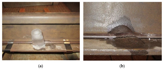
Figure 5.
Ice piece melting with use of traditional resistive heating (RH) device: (a) initial stage; (b) partially melted ice.
A similar test was performed for a prototype IH device. In order to check how operating frequency affects the melting efficiency, same ice pieces were placed on a device (Figure 6a,b), and melted under the influence of the IH system at various operating frequencies ranging from 40 to 90 kHz. All tests were performed at temperatures 0 °C and −10 °C, and the same initial temperatures of the IH device.

Figure 6.
Ice piece melting with use of the IH device: (a) initial stage; (b) partially melted ice.
Apart from tests focused on efficiency also electromagnetic compatibility aspects were tested. Since the IH device is a source of magnetic field required to correct operation, it is worth measure the field level at various distances. The measurements were made at distances from 0 to 1 m from the IH device. The magnetic field was measured with a TRACER MR100 VI-2 device.
3. Results and Discussion
3.1. Numerical Simulations
A simple geometry of IH coil and its vicinity is presented in Figure 7. The dimensions and material parameters were assumed based on the information on the IH device, but not all of them are public; therefore, some of them were assumed or slightly changed. The coil has turns of copper wires. The radiator is made of aluminum, and the walls are made of magnetic steel.

Figure 7.
Geometry of IH coil with enclosure, radiator and ice on its surface (dimensions in millimeters).
Numerical calculations of electromagnetic field were performed with FEMM 4.2. Figure 8 shows current density in the half cross-section of the configuration for two different frequencies and the same voltage on the coil. The eddy currents are localized mainly above the coil turns. Magnetic walls practically prevent the magnetic field to go under the device. An increase in frequency results in weaker eddy currents, because the current in the coil drops then due to an increase of impedance (see Figure 9).

Figure 8.
Localization of eddy-currents for a frequency of 40 kHz (a) and 70 kHz (b); the color scale is the same for both cases, half of the cross-section is shown.

Figure 9.
The resistance and reactance of the coil vs. frequency for 50 turns and assumed coil length 150 mm based on finite elements calculations.
Figure 10 shows the active power determined via Equation (2) with use of values of the resistance and reactance shown in Figure 9. It was assumed that the voltage on the coli terminals was constant, and the values of power are expressed as , where denotes the power at a frequency of 10 kHz. It is visible that the power strongly drops with frequency. This is confirmed later in Section 3.4.

Figure 10.
The resistance and reactance of the coil vs. turns number and assumed coil length 150 mm based on finite elements calculations for a frequency of 40 kHz and 70 kHz.
In the next step, temperature calculations were performed with Comsol software. The results for a frequency of 40 kHz and an initial temperature of 0 °C are presented in Figure 11. Despite of the fact that eddy currents are localized mainly near the coil turns, the temperature of the radiator is equalized practically at all stages of heating. Figure 12 shows the temperature of the radiator surface during a period of 30 min of simulation (dashed lines) for a frequency of 40 kHz and initial temperatures of 0 °C and −10 °C. In addition, the solid lines show the measured temperatures (see Section 3.3). It follows that the initial stage of heating simulation stays in good agreement with measurement. However, the numerical simulation and the measurement are different after several minutes from the beginning. The discrepancy originates from simplified model of calculations. Among others, it does not take into account additional cooling of the radiator by the water from ice melting.

Figure 11.
Temperature distribution (°C) around IH device (40 kHz, 2 A, 50 turns) for an initial temperature of 0 °C after 2 min (a), 4 min (b), 6 min (c), 8 min (d).

Figure 12.
The temperature of the radiator surface vs. time for a frequency of 40 kHz and initial temperatures of 0 °C and −10 °C—simulation (solid lines) and measurement (dashed lines).
3.2. Melting Time
The fundamental indicator of the devices under research is time required to melt ice piece. The times measured during the research are shown in Table 1.

Table 1.
Times of ice piece melting by RH and IH devices at various operating conditions
The RH device required around 29 and 49 min to melt the ice piece completely at initial temperatures of 0 °C and −10 °C, respectively. The times for the IH device were around 56–190% and 41–160% of that for RH device, respectively. The higher operating frequency resulted in slower ice melting. At first, this may seem strange, because it could be expected the opposite tendency—the higher frequency the quicker field changes and the higher eddy currents resulting in higher energy dissipation and quicker ice melting. However, this is not the case, because the IH device design results in variable power consumption when frequency is changed—the higher the frequency the lower the power consumed (see Section 3.4). This is a result of the fact that an increase in frequency causes also an increase in load resistance as well as coil reactance as shown in Section 3.1. As a consequence, the current drops and the power consumption is smaller than for lower frequency. In the frequency range from 40 to 70 kHz the IH device gives smaller melting times than those with use of an RH device. However, a significant reduction in the operating frequency of the system increased the power of the IH device, which resulted in excessive heating of the power supply and control system as shown in the following subsection.
3.3. Temperature Values
Knowledge of temperature is an important quantity in heat transfer. In the research the temperature was measured in control points in each system. In the first stage of the research an empty run was performed, in which no ice was present in the rail with RH device. Figure 13 shows temperature of the rail neck and foot vs. time for initial temperature 0 °C. It follows that temperature difference between the neck and foot are quite large. Hence, in case of absence of ice or snow the largest heat receiver is the rail itself. In real conditions this kind of operation can be encountered when the air temperature drops while neither snow nor ice is present in the turnout. In fact, the heating is usually unnecessary then.

Figure 13.
Foot and rail neck temperature vs. heating time in empty run of RH device for initial temperature 0 °C.
Figure 14 shows the rail neck and foot temperatures in case of presence of ice for initial temperature 0 °C. The image of temperature changes is now different. First of all, the temperatures of the foot and the neck are very close, and the differences are up to 2 °C. During the initial stage of heating the temperature of the foot is considerably higher than the neck temperature. This is probably caused by weak contact on the boundary rail-ice so that the heat is weakly transferred to ice. After some time, the surface of the ice is melted and the contact becomes better, so more heat is transferred to ice and the temperature between the rail neck and foot remains approximately constant at a level of 1 °C. An interesting phenomenon is inversion of neck and foot temperatures (time period around 1100–1400 s). This intensive heat transfer to ice is probably caused by large melting heat of ice. After the period of inversion, the temperature of the rail foot again becomes slightly higher than that of the neck. The ice piece was melted completely after around 29 min (see Table 1). A similar experiment with initial temperature −10 °C required over 49 min.

Figure 14.
Foot and rail neck temperature vs. heating time during ice piece melting by RH device at an initial temperature of 0 °C.
Figure 15 and Figure 16 show the surface temperature of the IH device for various frequencies vs. operation time for an initial temperature of 0 °C and −10 °C, respectively. It can be seen that the temperature is the higher the lower the frequency. As a result, the shortest melting times are for the lowest operating frequency (see Table 1). At first glance, this may seem strange, but when checking the power consumption (Table 2) it follows that the device takes much higher power at lower frequencies. The power is mainly transferred to the metal case via eddy currents, therefore more heat per unit of time is generated, and this gives a quicker and stronger rise to temperature.

Figure 15.
Temperature of IH device surface vs. time at different operating frequencies for an initial temperature of 0 °C.

Figure 16.
Temperature of IH device surface vs. time at different operating frequencies for an initial temperature of −10 °C.
Table 2.
Power consumption of RH and IH devices.
The temperature of IH device surface is much higher than that obtained on rail surface with RH device. For a frequency of 40 kHz the temperature reaches even 50 °C. However, when ice is spread all over the IH device surface, such high temperatures will not be reached and the heat may be even more efficiently transferred to the ice. Besides, the RH device is fixed to the stock rail, whose large heat capacity and large mass results in much lower temperatures compared to those of IH device.
3.4. Power and Energy Consumption
To detect the most suitable frequency it is necessary to compare power and energy taken by the RH and IH devices, because smaller times of ice melting by the IH device can be a result of larger power used. To investigate this, the power consumption of each device at various operating conditions was measured (Table 2). The values for both devices cannot be, however, compared directly, because one RH device is dedicated for about three railroad ties, whereas one IH device is placed between two ties. In the first approximation, around three IH devices are required instead one traditional RH device. This may lead to inefficient ice melting on the ties, therefore additional three IH devices may be required to be placed on each tie (or rather in the saddles on which the switch rail is placed). Hence, Table 2 shows also power of a group of 3 or 6 IH devices as equivalent to a single RH device. It follows that a group of 3 or 6 IH devices require 15–60% and 30–120% of a single RH device power, depending on frequency, where the higher the frequency the lower the power required.
However, power consumption is not quite informative, as it is energy which from the point of energy savings is the most important factor. Knowing power consumption and melting time, it is easy to calculate the energy consumed. The results are presented in Table 3. It shows results for two temperatures (0 °C and −10 °C) for two scenarios with 3 or 6 IH devices. First of all, it follows that in every case the energy consumption by IH devices is much less than the energy required by RH device. In case of 0 °C and 3 IH devices it is around 28–33%. When the temperature is lower, the ratio seems even more beneficial (22–24%). Even doubling the number of IH devices still keeps the IH/RH energy consumption at a very good level of 40–60%. This means that the IH device has a huge potential in energy savings related with heating of railroad turnouts.
Table 3.
Equivalent energy consumption of RH and IH devices when melting sample ice piece.
Table 1, Table 2 and Table 3 allow us selecting the optimal operation frequency with respect to time or energy savings. Table 1 indicates that lower frequency results in quicker operation, but it may require even higher power than an RH device. The higher power does not indicate, however, higher energy consumption, because the operation time is shorter. By analyzing Table 3 it can be stated that the highest energy savings are reached for a frequency of around 70 kHz.
It is worth to compare directly RH and IH devices assuming the same operation time. First, the frequency for which ice melting time is the same as with RH device is determined. By analyzing Table 1 for 0 °C it follows that the frequency is between 70 and 80 kHz. Then, using linear interpolation, one obtains a frequency of 72.5 kHz. This is illustrated in Figure 17a. This value can be used then to find the power used by a single RH device (see Figure 17b), which yields around 84 watts.

Figure 17.
Determination of frequency and power used by a single RH device to melt ice piece at the same time as the RH device: (a) determination of frequency; (b) determination of power used.
The length of a traditional 900 W RH device is 2.8 m. As indicated above, at least three IH devices should be used instead a single RH one. Hence, the power consumed by a traditional radiator during lab tests is 869.2 W, whereas three IH heat sources require 3 × 84 W = 252 W. This is around 29% of that for RH device. Even for six IH devices the required power will be 58% of that for RH device. This means really high energy savings.
3.5. Electromagnetic Compatibility Aspects
The magnetic flux density at various frequencies and distance from the IH device is shown in Figure 18. The field values are below 4.5 μT. The highest field values are for the lowest frequencies. This is a result of two factors: (i) at higher frequencies the power taken is smaller as shown in Table 2, so the current in coil is smaller (assuming unchanged voltage at coil terminals); (ii) at higher frequencies the skin depth is smaller and the field is more strongly attenuated by the metal case of coil and the radiator. In average, the magnetic field values decrease with an increase in frequency, although there are some disturbances in particular values. The disturbances originate probably from imprecise placement of the field meter. Besides, the expected dependence of the field decrease with increasing distance was confirmed. At a distance above around 5 cm above the IH device surface the magnetic flux density drops below 1 μT. This is very low; for example, Earth’s magnetic field is at a level of 30–60 μT. Of course, the two fields have different frequencies (0 Hz for Earth’s magnetic field, and 40–100 kHz for IH device), but this shows that the B field outside the IH device is very low. The above values indicate that the device should not affect any nearby infrastructure.
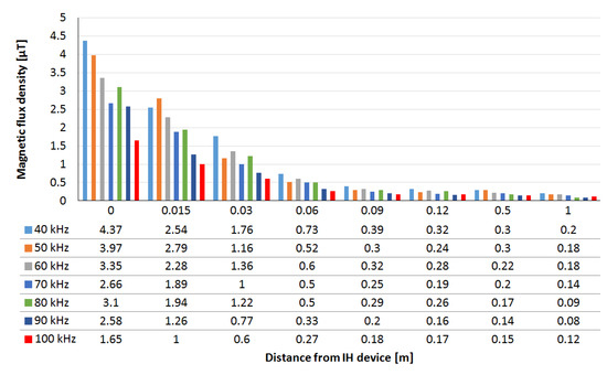
Figure 18.
Magnetic flux density vs. distance from the IH radiator for various operating frequencies.
4. Conclusions
The tested IH device is an innovative solution that uses the phenomenon of electromagnetic induction. The heat is generated mainly due to eddy currents in the metal case of the device. It can be used in countries where the winter conditions force electrical heating of railway turnouts. This solution makes it possible to heat the turnouts in a more rational way. First of all, it generates heat directly into the ice or snow. Secondly, it offers selectivity by heating only those places which require this. In addition, it also offers a possibility of adjusting frequency to obtain optimal operating conditions. Finally, it is compatible with the currently existing supervision and control systems.
The results of the tests show that although the tested IH device has the ability to set different operating frequencies, there is an optimal frequency (approx. 70 kHz in the case of the tested device) ensuring the highest energy savings. By comparison of the operation of traditional RH and the IH devices it was shown that even around 70% energy savings can be obtained keeping the ice melting time at the same level. Lower frequencies result in shorter times of operation, but require higher powers, although usually smaller than the traditional RH device. The magnetic field decreases quickly with the distance from the device, and should not affect the nearby infrastructure. Further research will be focused on numerical analysis of electromagnetic field, temperature distribution and heat transfer.
Author Contributions
Conceptualization, R.Ż. and P.J.; methodology, R.Ż., P.J. and T.S.; software, R.Ż.; validation, P.J; formal analysis, P.J.; investigation, R.Ż.; resources, R.Ż.; data curation, R.Ż.; writing—original draft preparation, R.Ż.; writing—review and editing, P.J. and T.S.; visualization, R.Ż., P.J. and T.S.; supervision, P.J. All authors have read and agreed to the published version of the manuscript.
Funding
This research received no external funding. The lab tests in climatic chamber and the APC were funded by the Czestochowa University of Technology under BS/PB-3-300-3011/20/P.
Institutional Review Board Statement
Not applicable.
Informed Consent Statement
Not applicable.
Data Availability Statement
Not applicable.
Acknowledgments
The authors wish to thank the PKP Polskie Linie Kolejowe S.A. (Polish Railway Lines Joint Stock Company) who allowed the measurements of RH and IH devices in operating conditions. The authors wish to thank the producer of the IH device prototype who shared the device for laboratory tests.
Conflicts of Interest
The authors declare no conflict of interest.
References
- Polish Railway Lines JSC Standard Iet-1. Manual of Operation and Maintenance of Electric Heating Devices for Turnouts; PKP Polskie Linie Kolejowe, S.A.: Warsaw, Poland, 2014. (In Polish) [Google Scholar]
- Kiraga, K.; Szychta, E.; Andrulonis, J. Chosen methods heating crossover railway system—inspection article. Przegląd Elektrotechniczny 2010, 2, 247–252. (In Polish) [Google Scholar]
- Flis, M. Analysis of the Energy Efficiency of Electric Heating of Railway Turnouts. Ph.D. Thesis, Gdańsk University of Technology, Gdańsk, Poland, 2018. (In Polish). [Google Scholar]
- Polish Railway Lines JSC Technical Standards. Detailed Technical Conditions for the Modernization or Construction of Railway Lines up to a Speed of Vmax ≤ 200 km/h (for Conventional Rolling Stock)/250 km/h (for Rolling Stock with Tilting Body), Version 2.0; adopted for use by a resolution of the Management Board No 1208/2017; Polskie Linie Kolejowe, S.A.: Warsaw, Poland, 2017. (In Polish) [Google Scholar]
- Polish Standard PN-EN 50121-2:2006. Railway Applications—Electromagnetic Compatibility—Part 2: Emission of the Whole Railway System to the Outside World; Polish Committee of Standardization: Warsaw, Poland, 2006. [Google Scholar]
- Żelazny, R. Switch Heating Electrical Equipment and External Lighting at PKP Polish Railway Lines. Sci. Lett. Rzesz. Univ. Technol. 2017, 2, 41–50. (In Polish) [Google Scholar]
- Żelazny, R. Quality of electricity in power lines for receivers PKP Polish Railway Lines S.A. Sci. Lett. Rzesz. Univ. Technol. 2018, 1, 37–48. (In Polish) [Google Scholar]
- Flis, M. Energy efficiency analysis of railway turnout heating system with a melting snow model heated by classic and contactless heating method. Arch. Electr. Eng. 2019, 68, 511–520. [Google Scholar]
- Flis, M. Contactless turnouts’ heating for energy consumption optimization. Arch. Electr. Eng. 2020, 69, 133–145. [Google Scholar]
- Kiraga, K.; Szychta, E. Research of selected electric and magnetic properties of railway rail. Arch. Elecrical Eng. 2012, 61, 347–357. [Google Scholar] [CrossRef]
- Szychta, E.; Szychta, L.; Luft, M.; Kiraga, K. Application of 3D Simulation Methods to the Process of Induction Heating of Rail Turnouts. In Infrastructure Design, Signalling and Security in Railway; Perpinya, X., Ed.; Intech: Rijeka, Croatia, 2012; pp. 295–432. [Google Scholar]
- Szychta, E.; Szychta, L.; Luft, M.; Pietruszczak, D. The results of the rail induction heating by the current inverter with the parallel resonant circuit. Przegląd Elektrotechniczny 2016, 11, 203–207. [Google Scholar] [CrossRef][Green Version]
- Oh, H.S.; Park, C.B.; Lee, S.H.; Lee, J.B.; Kim, T.H.; Lee, H.W. A study on deicing for railway turnouts using 250 kHz 200 W class induction heating system. AIP Adv. 2019, 9, 125229. [Google Scholar] [CrossRef]
- Wołoszyn, M.; Jakubiuk, K.; Flis, M. Analysis of resistive and inductive heating of railway turnouts. Przegląd Elektrotechniczny 2016, 4, 52–55. [Google Scholar] [CrossRef][Green Version]
- Szychta, E.; Szychta, L. Comparative Analysis of Effectiveness of Resistance and Induction Turnout Heating. Energies 2020, 13, 5262. [Google Scholar] [CrossRef]
- Polish Standard PN-EN IEC 61000-3-2:2019. Electromagnetic Compatibility (EMC)—Part 3-2: Limits—Limits for Harmonic Current Emissions (Equipment Input Current ≤ 16 A Per Phase); Polish Committee of Standardization: Warsaw, Poland, 2019. [Google Scholar]
- Polish Standard PN-EN 61000-3-12:2012. Electromagnetic compatibility (EMC)—Part 3-12: Limits—Limits for Harmonic Currents Produced by Equipment Connected to Public Low-Voltage Systems with Input Current > 16 A and ≤ 75 A Per Phase; Polish Committee of Standardization: Warsaw, Poland, 2013. [Google Scholar]
- Polish Railway Lines JSC Standard Iet-5. Design Guidelines for Electric Heating Devices for Turnouts. Vol. 1 Design of Track and Trackside Installations, Selection of Heaters; PKP Polskie Linie Kolejowe S.A.: Warsaw, Poland, 2015; Volume 1. (In Polish) [Google Scholar]
- Polish Railway Lines JSC Standard Iet-118. Normative Document 01-8/ET/2008: Electric Heaters for Heating Turnouts; PKP Polskie Linie Kolejowe S.A.: Warsaw, Poland, 2008. (In Polish) [Google Scholar]
- Polish Railway Lines JSC Standard Iet-119. Normative Document 01-9/ET/2008: Holders of Heaters for Electric Heating of Turnouts; PKP Polskie Linie Kolejowe S.A.: Warsaw, Poland, 2008. (In Polish) [Google Scholar]
- Polish Railway Lines JSC Standard Iet-117. Normative Document 01-7/ET/2008: Electric Heating Transformer Box for Turnouts; PKP Polskie Linie Kolejowe S.A.: Warsaw, Poland, 2008. (In Polish) [Google Scholar]
- Polish Railway Lines JSC Standard Iet-116. Normative Document 01-6/ET/2008: Switchboard for Electric Heating of Turnouts; PKP Polskie Linie Kolejowe S.A.: Warsaw, Poland, 2008. (In Polish) [Google Scholar]
Publisher’s Note: MDPI stays neutral with regard to jurisdictional claims in published maps and institutional affiliations. |
© 2021 by the authors. Licensee MDPI, Basel, Switzerland. This article is an open access article distributed under the terms and conditions of the Creative Commons Attribution (CC BY) license (http://creativecommons.org/licenses/by/4.0/).