Article

A New MPPT Algorithm for Photovoltaic Power Generation under Uniform and Partial Shading Conditions

1
Electrical Engineering Department, Politeknik Elektronika Negeri Surabaya, Surabaya 60111, Indonesia
2
Electrical Engineering Department, California Polytechnic State University, 1 Grand Avenue, San Luis Obispo, CA 93407, USA
*
Author to whom correspondence should be addressed.
Energies 2021, 14(2), 483; https://doi.org/10.3390/en14020483
Submission received: 12 December 2020 / Revised: 12 January 2021 / Accepted: 12 January 2021 / Published: 18 January 2021
(This article belongs to the Special Issue Photovoltaic Systems: Modelling, Control, Design and Applications)

Abstract

:
During its operation, a photovoltaic system may encounter many practical issues such as receiving uniform or non-uniform irradiance caused mainly by partial shading. Under uniform irradiance a photovoltaic panel has a single maximum power point. Conversely under non-uniform irradiance, a photovoltaic panel has several local maximum power points and a single global maximum power point. To maximize energy production, a maximum power point tracker algorithm is commonly implemented to achieve the maximum power operating point of the photovoltaic panel. However, the performance of the algorithm will depend on operating conditions such as variation in irradiance. Presently, most of existing maximum power point tracker algorithms work only in a single condition: either uniform or non-uniform irradiance. This paper proposes a new maximum power point tracker algorithm for photovoltaic power generation that is designed to work under uniform and partial shading irradiance conditions. Additionally, the proposed maximum power point tracker algorithm aims to provide: (1) a simple math algorithm to reduce computational load, (2) fast tracking by evaluating progress for every single executed duty cycle, (3) without random steps to prevent jumping duty cycle, and (4) smooth variable steps to increase accuracy. The performances of the proposed algorithm are evaluated by three conditions of uniform and partial shading irradiance where a targeted maximum power point is located: (1) far from, (2) near, and (3) laid between initial positions of particles. The simulation shows that the proposed algorithm successfully tracks the maximum power point by resulting in similar power values in those three conditions. The proposed algorithm could handle the partial shading condition by avoiding the local maxima power point and finding the global maxima power point. Comparisons of the proposed algorithm and other well-known algorithms such as differential evolution, firefly, particle swarm optimization, and grey wolf optimization are provided to show the superiority of the proposed algorithm. The results show the proposed algorithm has better performance by providing faster tracking, faster settling time, higher accuracy, minimum oscillation and jumping duty cycle, and higher energy harvesting.

Graphical Abstract

1. Introduction

In the last decades, photovoltaic (PV) power generation has been attracting many researchers’ interests to investigate them in comparison with other renewable energy sources. PV offers benefits such as free fuel (sunlight), low operation and maintenance costs, noise free nature and simple construction. However, the main drawback of PV is its high initial cost, especially in the first construction. Therefore, to shorten the breakeven cost period, many researchers have investigated how to maximize the energy produced by PV such as using maximum power point tracker (MPPT). A typical MPPT structure for PV is shown in Figure 1. The MPPT algorithm must work properly under various condition of irradiance: in uniform and/or non-uniform irradiance.
The conventional MPPT algorithms under uniform irradiance that have been well studied are perturb and observe (P&O) [1] and incremental conductance (InC) [2] algorithms. P&O and InC algorithms are popular due to their ease of implementation. However, the P&O and InC have some issues such as continuous power oscillation at convergence and fail to track maximum power point (MPP) under rapid change of irradiance. To address these issues, variable step size-based algorithm which automatically adjusts perturbation steps was proposed. The basic principle of variable step is to adapt the perturbation amplitude according to the MPP position; the closer the operating point to MPP, the smaller step is used [3,4]. In [5], the variable step size is determined by fuzzy logic which results in many choices of step sizes. However, the fuzzy logic implementation requires complex algorithm and execution process. Adaptive variable step is implemented by checking any decreasing power during perturbation which means that the MPP is passed, then the step size is reduced by a constant value during iteration [6]. Another variable step size algorithm were proposed by detecting the area near MPP using dP/dV value [6] and using a scaling factor [7]. However, the scaling factor provides inconsistencies in the tracking speed to achieve the MPP under various irradiance level.
Model-based MPPT has been proposed to increase the tracking speed. In [8], a parameter-estimation-based MPPT was proposed. Solar irradiance and temperature are directly calculated by the algorithm to estimate the MPP. Another improvement on the MPPT algorithm was proposed with the fast-modeling approach based on the Lambert PV circuit model for partially shaded PV systems [9]. By using this approach, the MPP is determined by the numerical method based on the developed model. A novel MPPT algorithm was also proposed based on the PV module with the single diode model [10]. In this algorithm, a gradient-based updating law is utilized to find the optimum voltage value of MPP. Furthermore, a new model based MPPT (MBMPPT) was proposed to identify the MPP of each PV panel based on its characteristics [11]. Even though a fast-tracking feature is performed by the model based MPPT, this method requires high computational iterations to achieve the optimum solution.
Non-uniform irradiance and characteristic can occur on a PV panel. These phenomena generate local maxima power point (LMPP) and global maxima power point (GMPP) in the PV power characteristics. Non-uniform irradiance may be caused by dirty surface on PV panel or temporary shading due to cloud [12]. These conditions will reduce energy production in PV power plant [13,14]. The forecasting of energy production has been studied under these conditions [15]. Several forecasting methods are proposed to investigate the problems such as, repairing big data and neural networks [16,17]. Furthermore, the non-uniform characteristic can be caused by the non-similarity characteristics between PV panels in string connection or parallel connection [18]. Unfortunately, the MPPT methods mentioned above could not deal with these conditions. To overcome these problems, the artificial intelligence based MPPT was investigated to explore the most effective solution for GMPP without prior knowledge of the system’s model or utilize analytical method. artificial neural networks (ANN) [19,20,21,22] and fuzzy logic controllers (FLC) [23,24,25,26] have been explored by many researchers. Additionally, the hybrid AI based method was also proposed. In FLC for example, fuzzy rules are decided based on the knowledge of PV characteristics and its relationship to weather conditions. However, its performance depends on the determination of membership function and rules. Therefore, the performance depends on extensive training, which usually takes a long time and consumes significant computational power and large memory size.
In recent years, metaheuristic algorithms have been considered for MPPT. Metahueristic algorithms were originally designed to solve complex functions such as more than three dimensions equation, multi optimum values, etc. Metahueristic algorithms work effectively by using exploration and exploitation modes. Exploration mode is entering the new searching space while exploitation mode is searching within previous searching space [27]. To test a new metaheuristic algorithm performance, several complex equations are used such as Rastrigin, Ackley, etc. Metaheuristic bio-inspired algorithms have emerged for their ability in finding GMPP. Metaheuristic maximum power point tracker (MMPPT) methods such as ant colony optimization (ACO) [28,29,30], cuckoo search (CS) [31,32,33], firefly algorithm (FF) [34,35,36,37], whale optimization (WO) [38,39], differential evolution (DE) [40,41,42], grey wolf optimization (GWO) [43,44] and particle swarm optimization (PSO) [45,46,47,48] have been proposed. Some recent MPPT algorithms of PV system were proposed to specifically solve the partial shading problem. These bio-inspired algorithms can detect the GMPP by involving combination of possible solutions or using random variables. These algorithms apply several particles for each iteration to find possible solution. Evaluation will be taken after all particles deployed. High number of particles may increase accuracy or tracking speed. But at the same time may produce lower energy tracking. Moreover, unwanted power fluctuation is generated due to the random variables of combination and selection of the solution [40]. Similarly, unwanted fluctuation in the output power is caused by random walk (for example, Levy flight). Furthermore, power oscillation occurs in convergence due to the random variables in the above bio-inspired algorithms. To solve these problems, the method employs a threshold to lock to the best solution in convergence. However, the locking mechanism will lead to lower accuracy. Furthermore, random walk for particles in initialization may cause prolonged unstable starting period which may further cause premature convergences, thereby missing the GMPP [46,47,48]. The premature convergence occurs when the GMPP is not surrounded by initialization particles. Random walk or random variables helps to reach GMPP but at the same time it generates power oscillation. Note that, metaheuristic algorithms are designed originally to solve complex numerical optimization of three dimensions equation or higher dimension. In contrast, PV characteristic is only single dimension equation. Furthermore, its characteristics of random calculation to PV power generation has risk to power oscillation. To avoid this problem, the random number is removed in [49] from the voltage calculation equation of the conventional CS algorithm. Simple math is used to determine GMPP in this algorithm. To surround the GMPP, particles move from left to right side of GMPP or vice versa. However, this movement yields power oscillation due to the jump of duty cycle. In addition, it is important to guarantee the MPPT works in any condition, uniform or non-uniform. Some existing works have considered these issues, such as involving metaheuristic algorithm: Adaptive cuckoo search optimization algorithm [50], butterfly optimization algorithm [51], Jaya and DE [52], and multi-producer group-search-optimization [53]. The other algorithms are proposed by using complex algorithm such as: multiloops to detect MPP during uniform and partial shading [54], ANFIS-based [55], and novel spline-MPPT technique [56].
This paper proposes a MPPT algorithm for working under uniform and partial shading. The summary of issues in the existing MPPT algorithms and the key contributions of the proposed algorithm (PA) is shown in Table 1. Similar issues are put in the same category.

2. PV and Buck Converter Modeling

2.1. PV Cell Modeling

A PV cell can be modeled as single diode model or double diode model [57]. The single diode model of PV cell is the most popular due to its simplicity. A single diode ideal and practical model is shown by red and blue dotted line respectively in Figure 2. I P V and V are the current and voltage of cell terminal, respectively. I P V is resulted by I x , I D , and I R p represented in Equation (1) I x is DC current source model for electrical current produced by solar irradiance. I D and I R p is internal diode current and shunt resistance current, respectively. I D is represented in Equation (2). I o is the dark saturation current of the PV cell. q is the electronic charge ( q = 1.6 × 10 19 ) . V D is internal diode voltage. A is the ideality factor of each PV cell, also called emission coefficient. It is around 2 for crystalline silicon and is less than 2 for amorphous silicon. k is the Boltzmann’s constant (k = 1.3806505 × 10⁻²³). T 0 and S 0 are temperature and irradiance standard test conditions, respectively. I o is represented in Equation (3). I s o is Diode saturation current. T is the ambient temperature. E g is the bandgap energy of each PV cell, in eV. It is around 1.12 for crystalline silicon, and around 1.75 for amorphous silicon. V D is represented in Equation (4). The series R s and shunt resistors R P represent an internal resistance and leakage current respectively. I x is represented by Equation (5). I s c is short circuit current at PV cell terminal. S is the actual irradiance of PV panel. C t is temperature coefficient. I R p is represented by Equation (6). The total voltage of PV array connected in series is represented by Equation (7). The total current of PV array connected in parallel is represented by Equation (8). N s , N p , V s   and I p are number of PV cells, voltage and current in series array and in parallel array, respectively. Table 2 shows the detail electrical characteristics of PV panel used in this study extracted from ICA Solar Polycrystalline ICA100P. Series string connection of three panels is used to test the MPPT algorithms. Figure 3 shows the string panel characteristics of power-voltage (P-V) and current-voltage (I-V) curves demonstrating the effects of various uniform solar irradiance. Higher solar irradiance will significantly increase PV panel current and MPP, but it has small effect to open circuit voltage:
I P V = I x I D I R p
I D = I o e x p q V D A k T 0 1
I o = I s o T T 0 3 e x p q E g A k 1 T 0 1 T
V D = V + I P V · R s
I x = I s c S S 0 + C t T T 0
I R p = V D R P
V s = N s · V
I p = N p · I P V

2.2. Partial Shading and Its Effects

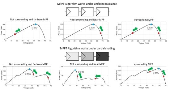
PV array with uniform irradiance have only one MPP at the knee of the curve I-V. PS occurs when PV array receive non uniform or different irradiance [58]. The number of maxima on each power-voltage curve is equal to the number of PV panel arrays. Figure 4 shows the PV characteristics used to test the algorithm in this paper. PV panel arrays consist of three PV panels which indicate by PV1, PV2 and PV3. Black dots and blue diamonds show LMPP and GMPP, respectively. The number of maxima is three points, according to number of PV panel arrays. Under uniform irradiance, PV panel arrays generate a single MPP as shown in red line in Figure 4. Contrary to partial shading, PV panel arrays generate LMPP and GMPP, as shown in blue, yellow, and green lines in Figure 4.

2.3. Buck Converter

Buck converter provides the interface between the PV array and the load. By regulating buck converter’s duty cycle, load impedance can be varied as viewed from the PV array side. This in turn enables the buck converter to push PV operating point at GMPP impedance. The buck converter circuit can be formulated by Equations (9)–(13):
V o = D · V i
D = t o n T s
L m i n = 1 D R 2 f
L f = V i V o i L f D
C f = 1 D 8 L V o V o f 2
where V i and V o are the input and output voltages, D is the duty cycle, t o n is PWM signal duration to turn on buck converter switch, T s is switching period, L m i n is the minimum inductance needed for continuous current operation, R is load resistance.   L f and C f are the filter inductor and capacitor, respectively. f is the switching frequency, V o is the load ripple voltage, and i L is the inductor ripple current [59]. Duty cycle 0% means open circuit and duty cycle 100% means short circuit to PV array. Table 3 lists the specifications of the buck converter used in the study. Components value are chosen from list of standard values charts to simulate real experimental system.

3. Proposed Algorithm

Figure 5 illustrates the MPP tracking concept according to proposed algorithm. The main idea of proposed algorithm works based on particles position. Each particle corresponds to operating point of duty cycle Dni and PV power Pni. To simplify the the illustration, minimum number of three particles are shown. It shows position of MPP Pm marked by blue diamond, duty cycle at MPP Dm, three particles of P1i green dots, P2i red dots and P3i yellow dots, and their duty cycle of D1i, D2i and D3i respectively. D3i is the highest duty cycle, D1i is the lowest, and D2i is between D1i and D3i. During the movement of particles, D1i, D2i and D3i cannot cross one another. They will be kept in the sequence wherein D1i is the smallest and D3i is the highest duty cycle. P2i is directed to the highest power point. Once P2i reaches the highest point, P1i and P3i will approach P2i.
The relationship of those three particles can be classified into four conditions as shown in Figure 5a–d. Imitating to metaheuristic algorithm principle operation of exploration and exploration mode, Figure 5a,b are exploration mode, while Figure 5c,d are exploitation mode. Figure 5a illustrates case 1, where P1i is the highest value. If P1i is the highest, P1i will be shifted to new position by reducing duty cycle D1i. P2i will move to previous position of P1i. P3i will move to previous position of P2i. This procedure is repeated until P2i > P1i. Figure 5a illustrates case 2, where P3i is the highest value. If P3i is the highest, P3i will be shifted to new positions by increasing duty cycle D3i. P2i will move to previous position of P3i. P1i will move to previous position of P2i. This procedure is repeated until P2i > P3i. Figure 5c,d illustrate case 3, where P2i is the highest value: P2i > P3i and P2i > P1i. There are two possibilities of case 3: P2i is at the left side or right side of Pm as shown by Figure 5c. P1i and P3i will approach P2i. Under certain conditions, P3i can be higher than P2i. If this condition occurs, the case will change from case 3 to case 2. Another possibility is P2 at the right side of Pm as shown by Figure 5d. P1i and P3i will approach P2i. Under certain conditions, P1i can be higher than P2i. If this condition is occurred, the case will change from case 3 to case 1.
The detailed implementation of the proposed algorithm is shown in Figure 6 and can be described as follows.
Step 1: Set the initial duty cycles of D10, D20 and D30.
Choose D10 as the lowest, D20 as the middle and D30 as the highest. Measure the PV voltage and current, and then calculate the obtained PV power respectively as P10, P20 and P30. These three particles are memorized, and then they will be identified.
Step 2: Check relationship between P1i, P2i and P3i.
If P2i > P1i and P2i > P3i is false then enter the exploration mode, which falls to Case 1 or Case 2.
If P2i > P1i and P2i > P3i is true then enter the exploitation mode, which falls to Case 3.
Step 3: Duty cycle calculation.
Case 1 is identified by condition of P1i > P3i. If case 1 is true, then update the duty cycle by the following equations:
D1i+1 = D1i − (D2i − D1i)·k
D2i+1 = D1i; D3i+1 = D2i
P2i+1 = P1i; P3i+1 = P2i
Constant k is chosen a value between 0 and 1. Copying data is implemented in case 1 for D2i+1, D3i+1, P2i+1 and P3i+1. Copying data follows Equation (14).
Case 2 is identified by condition of P3i > P1i. If case 2 is true, then update the duty cycle by the following equations:
D3i+1 = D3i + (D2i − D3i)·k
D1i+1 = D2i; D2i+1 = D3i
P1i+1 = P2i; P2i+1 = P3i
Copying data is implemented in case 2 for D1i+1, D2i+1, P1i+1 and P2i+1. Copying data follows Equation (15).
Case 3 is identified by condition of P2i > P1i and P2i > P3i. P2i can be laid on the left side or the right side of Pm. P1i and P3i approach P2i by regulating D1i+1 and D3i+1. Duty cycle of D1i+1 and D3i+1 for case 3 is determined by the following equations:
D1i+1 = D1i + (D2i − D1i)·k
D3i+1 = D3i − (D2i − D3i)·k
D1i+1 and D3i+1 approach D2i D1i+1 and D3i+1 are executed alternately during iterations.
Step 4: Power measurement according to case number.
In case 1 and case 2, power measurements for P1i+1 and P3i+1 are taken, respectively. In case 3, power measurements for P1i+1 and P3i+1 are taken alternately according to Equation (16a) or Equation (16b).
In this proposed algorithm, simple math is used to perform exploration and exploration mode. A data copying technique is proposed to increase tracking speed during exploration mode. This technique is implemented to avoid same search space which may waste number of iterations and helps to fast tracking. Fast tracking is implemented by evaluating progress for every single executed particle/duty cycle. It can be seen from Figure 6, for each iteration only once measurement of power is needed. This is contrary to metaheuristic algorithm in which every iteration is evaluated after implementation of all particles. Furthermore, the proposed algorithm has smooth variable steps. At the beginning of iteration, a large step is produced by the algorithm considering the far distance between particles position. By the time, the step becomes smaller, the particle distance is getting closer. At near convergence, particles will be at very close position. The value of duty cycle is close to each other, including the power. Consequently, without involving random calculation, steps are kept very small and the results show less power fluctuation. Additionally, small steps will help increase accuracy in reaching MPP at the exact value. Conversely, if random calculation is used, the calculation can be independent from particle distance. Hence, steps can be large compared to the particle distance which produce jumping duty cycle and high-power fluctuation.

4. Simulations and Results

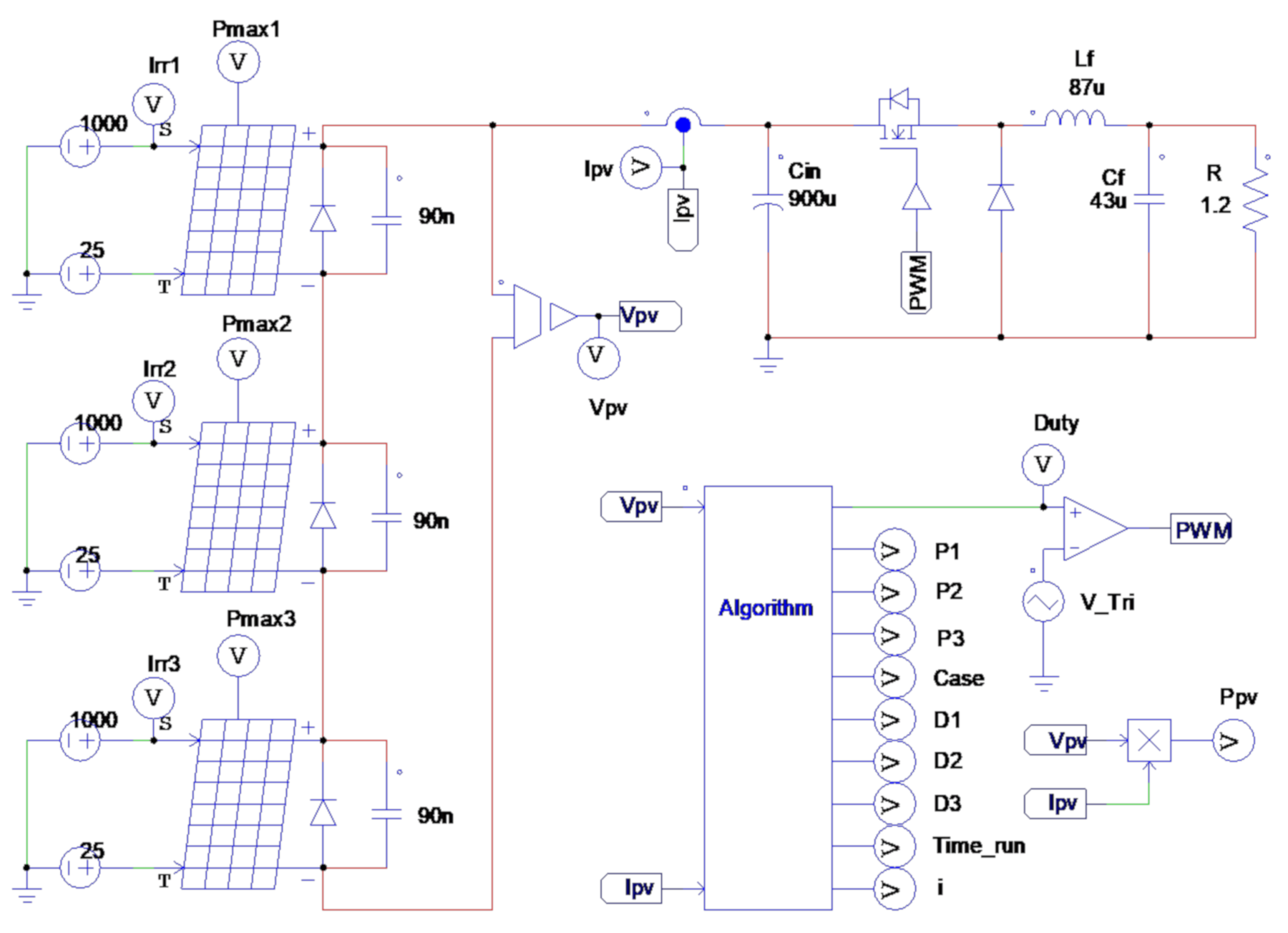
Algorithm is implemented using PSIM, a simulation solution for all power electronics applications. Figure 7 presents the PSIM simulator circuit for the overall system. An overall system specification is shown in Table 3. The PV string consisting of three PV panels are used to simulate single MPP or multi MPP. Several MPPT algorithms including the proposed algorithm are tested under several test conditions. The test conditions are:
(a)
DE, FF, PSO and GWO algorithms are implemented using five particles, while the proposed algorithm is using three particles to simplify the coding implementation.
(b)
Uniform irradiance tests: constant irradiance at STC (1000 W/m2 and 25 °C), targeted MPP is (Test 1) far from initial positions of particles, (Test 2) near initial positions, and (Test 3) laid between initial positions.
(c)
Partial shading tests: targeted GMPP is (Test 4) laid between initial particles, (Test 5) near initial particles, and (Test 6) far from the initial particles with similar value of power points.
(d)
To verify the performance, each algorithm is tested 10 times for each test 1–6. Duration of energy harvesting process in simulation is 2 s. Sample test is provided in Section 4.1. Uniform Irradiance test and 4.2. Partial Shading.
The effectiveness of the algorithms is analyzed in terms of tracking time, settling time, power convergence, steady-state oscillations, actual tracked maximum power ( P M P P A ), actual harvested energy ( E M P P A ), power tracking accuracy ( η P ), and energy tracking accuracy ( η E ). P M P P T is the maximum power that can be produced by PV panel according to GMPP. E M P P T is the harvested energy during the operation of PV panel at GMPP. The tracking time is the time taken to track the GMPP for the first time. The settling time is the time taken by all the particles to settle at GMPP without further power oscillation or fluctuation. The power tracking accuracy is calculated by comparing P M P P A and P M P P T :
η P = P M P P A P M P P T × 100 %
The energy tracking accuracy is calculated by comparing E M P P A and E M P P T :
η E = E M P P A E M P P T = P M P P   A × t P M P P T × t × 100 %
where t is the duration of energy harvesting process.

4.1. Uniform Irradiance Test

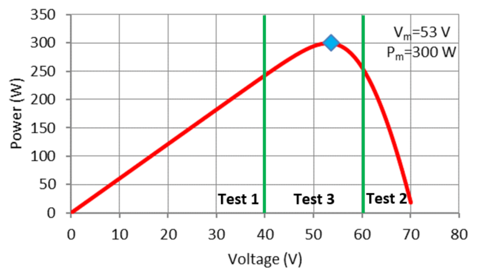
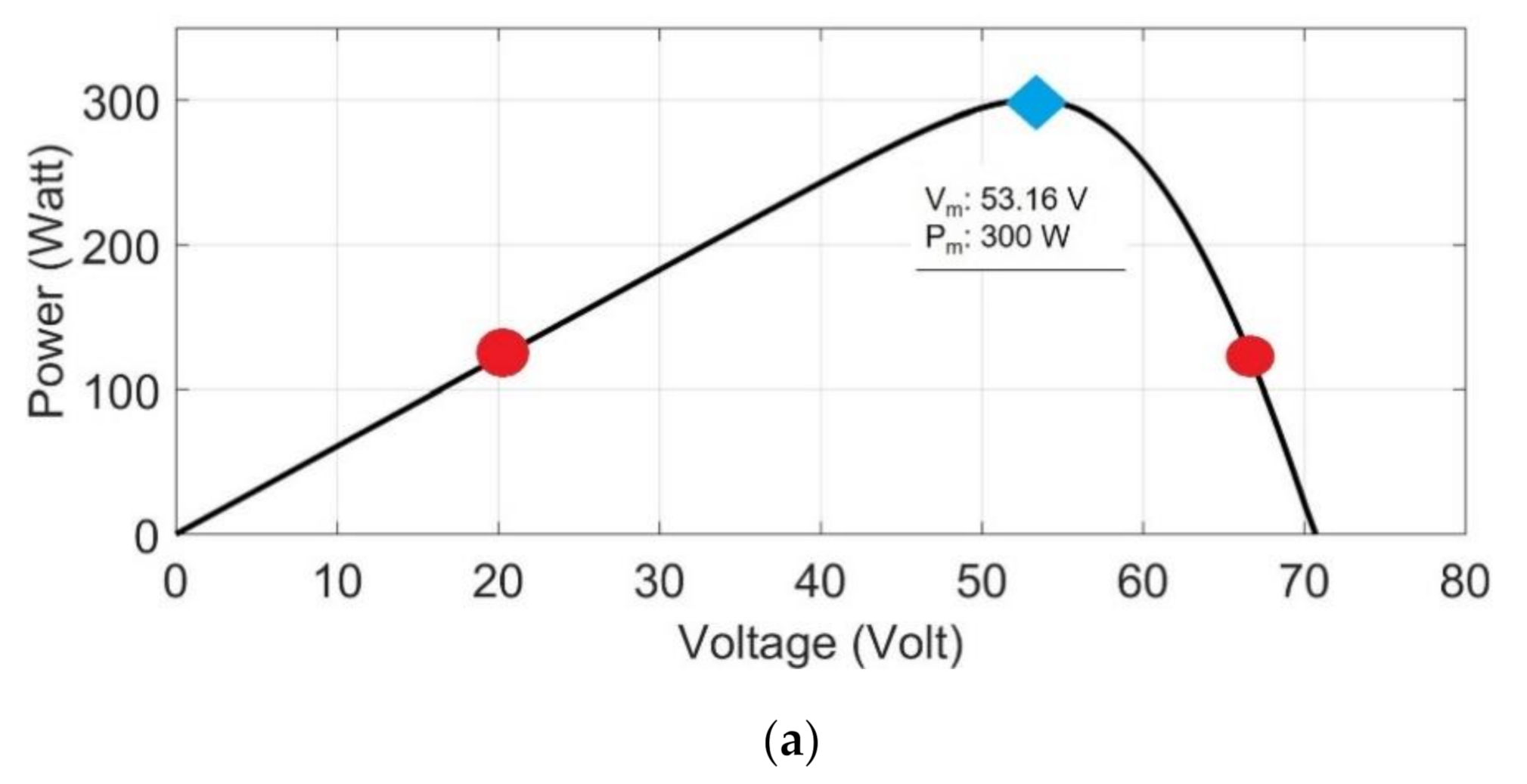
PV array is operated at STC which results in a total Pm = 300 W and Vm = 53.16 V. Duty cycle at MPP Dm is 34%. Initial particles are chosen in the three areas of Test 1, 2 and 3 as shown in Figure 8. Tests 1 and 2 are to verify the performance of exploration mode of algorithm. In test 1 and 2, initial particles are not surrounding MPP. Each algorithm is tested to shift its operating point using exploration mode to approach MPP. Test 3 is to verify the performance of exploitation mode. In exploitation mode test, tracking speed and accuracy are observed.

4.1.1. Test 1: Initial Particles at Left Side of MPP

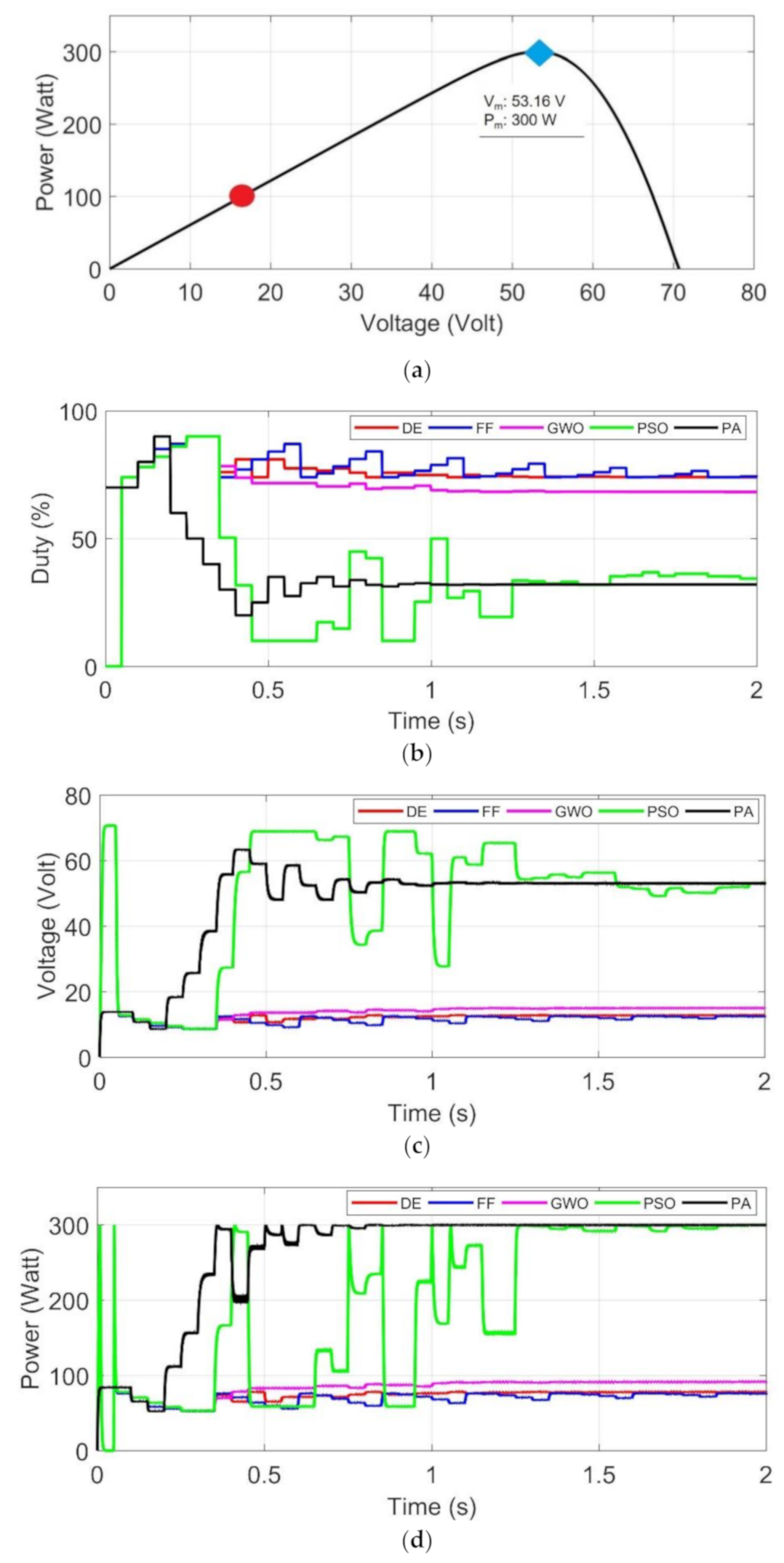
In Test 1, initial particles for each algorithm are limited between duty cycles of 70% and 90%. Targeted MPP is far from initial positions of particles. Exploration mode is tested to reach a far targeted MPP. Figure 9a shows the MPP position at blue diamond and the initial positions of particles of all algorithms, indicated by red dot. The initial particles position are around 15 V and 80 W. Figure 9b–d confirm that PSO and PA algorithm can track MPP. However, other algorithms cannot track MPP. At t = 0.4 s, the PA algorithm tracks the MPP and once time tracked never leaving the MPP. At steady state, the PA keeps the duty cycle at a constant value of 34%. Figure 9d shows, without random walk PA, there is no power oscillation after tracks MPP at t = 0.8 s. PSO can track the MPP at t = 0.45 s by the help of large random walk. Conversely, large random in PSO algorithm may cause unwanted duty cycle. It shows in Figure 9b–d PSO algorithm leaves and returns to MPP several times. PSO algorithm cannot converge until the final time of simulation. FF, DE and GWO reach premature convergence. They lose direction to reach MPP although the random walk helps trying to find the MPP. In this test, PA shows its best exploration performance compared to other algorithms. The maximum power achieved by PA is the highest by reaching 300 W as compared to 77, 75, 299 and 90 W achieved by DE, FF, PSO, and GWO. PA has 100% accuracy followed by PSO 99.66%, GWO 30%, DE 25.66%, and FF has the least accuracy of 25%. Energy harvesting by PA is the highest per 2 s at 523 Ws, followed by PSO 381, GWO 168, DE 146 and FF 72 Ws.

4.1.2. Test 2: Initial Particles at Right Side MPP

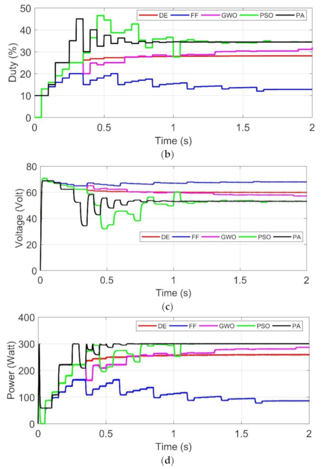
In test 2, initial positions of particles are at near left side of MPP. The duty cycle is set around 10% to 30%. Exploration mode is tested to reach close to the targeted MPP. As shown in Figure 10a, initial position of particles are indicated by red dot. The initial operating points are around 70 V and 150 W. Figure 10b shows duty cycle movement during iterations. PA and PSO can track MPP. PA tracks MPP at t = 0.6 s and settling time t = 0.8 s, PSO at t = 1.1 s and t = 1.7 s, respectively. Although PSO tracks the MPP, unwanted duty cycle and power oscillations occur as shown in Figure 10b. DE and GWO approach the MPP but take longer time than PA and PSO. FF loses direction to MPP. In this test, PA shows its best exploration performance compared to other algorithms. The maximum power achieved by PA and PSO is the highest by reaching 300 W as compared to 285 W, 257 W, and 84 W achieved by GWO, DE, and FF. PA and PSO has 100% accuracy followed by GWO 95%, DE 85.67%, and FF has the least accuracy of 28%. Energy harvesting by PA is the highest per 2 s at 549 Ws, followed by PSO 521, GWO 476, DE 469 and FF 212 Ws.

4.1.3. Test 3: Initial Particles at Surrounding MPP

In test 3, targeted MPP is laid between the lowest and the highest initial duty cycles. Exploitation mode is tested in this test. The duty cycle is set around 20% to 40%. Figure 11a shows initial particles positions of the highest and lowest initial duty cycles, MPP is between them. The initial operating points are between 43–65 V and 155–250 W. PA algorithm tracks MPP at t = 0.6 s and it is the fastest tracking. Other algorithms track MPP at different time, PSO at t = 1 s, and FF at t = 1.2 s. DE and GWO approach MPP until the final time of simulation. PSO algorithm continues random walk, which produces unwanted power oscillations near convergence. The settling time of PA is reached at t = 1.1 s and PSO at t = 1.9 s. DE, FF and GWO exceed 2 s. GWO and FF algorithms show the random walk which produces jump away duty cycle and sudden power oscillations. It is recorded that GWO at t = 0.6 and t = 1 s and FF at t = 0.56 and t = 0.81 s produces unwanted random duty cycle and high-power oscillations, which shown in Figure 11b,d respectively. It can be seen in zoomed window of Figure 11b–d that PA shows fast tracking without producing unwanted oscillation. DE slowly approaches MPP and produces less power oscillation. Each algorithm shows different accuracy results of tracking Pm. The maximum power achieved by PA and PSO is the highest. PA and PSO reach 300 W as compared to 299, 298 and 296 W achieved by FF, GWO, and DE. Energy harvesting at 2 s by PA is the highest with 573 Ws, followed by PSO 572, GWO 571, DE 571 and FF 567 Ws. At the end of simulation, PA algorithm shows the highest accuracy, energy harvesting and the fastest convergence.

4.2. Partial Shading

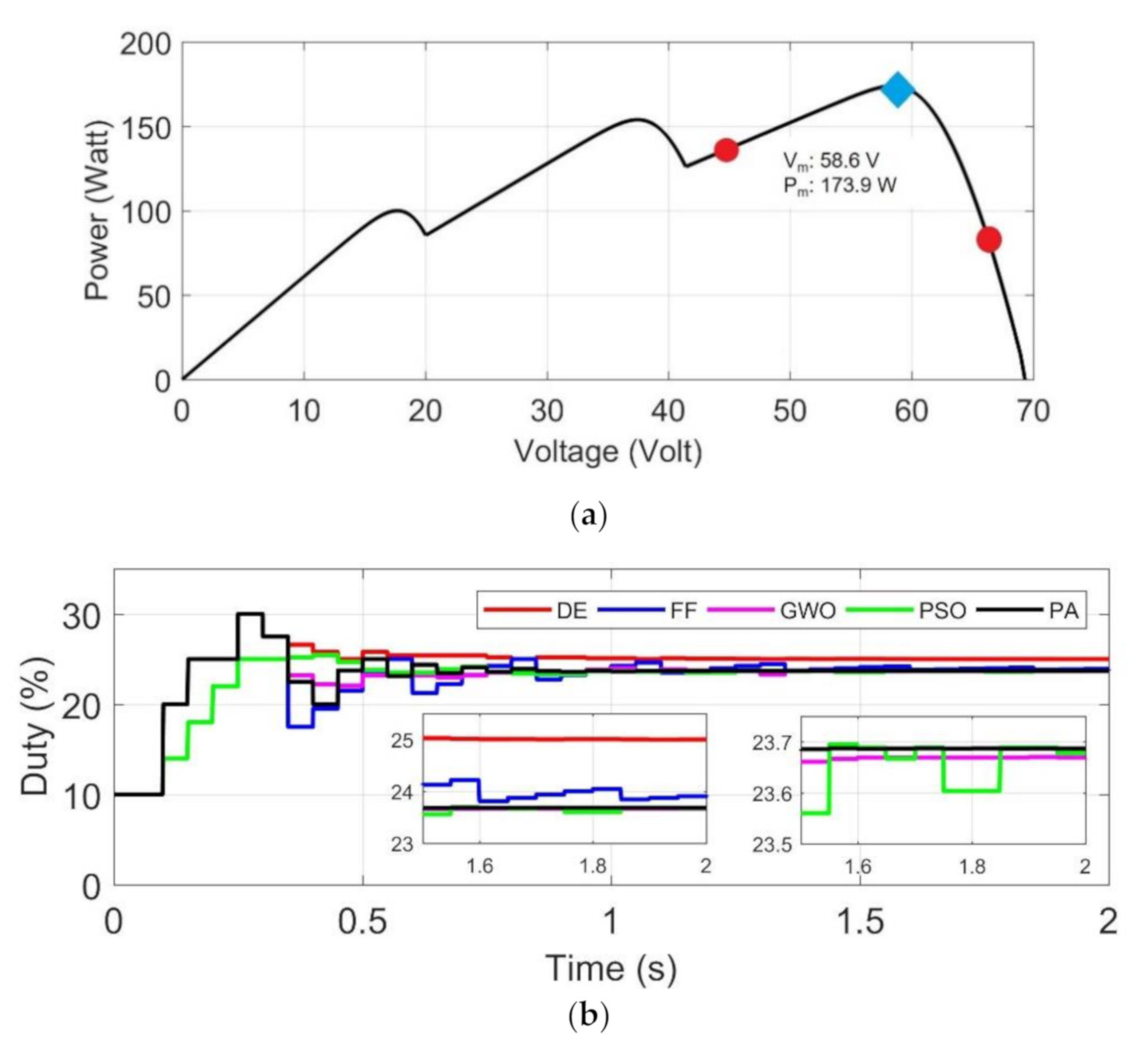
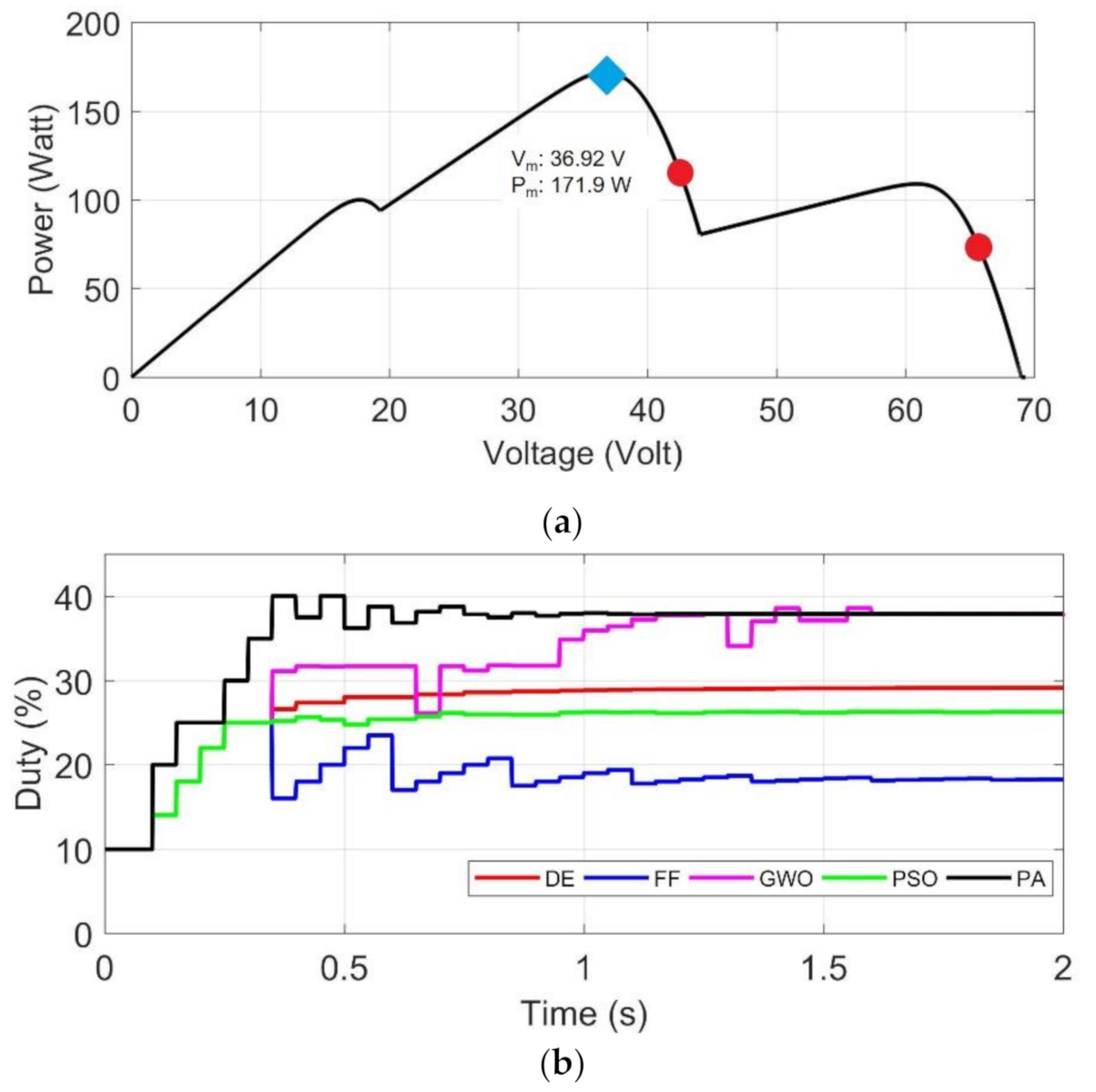
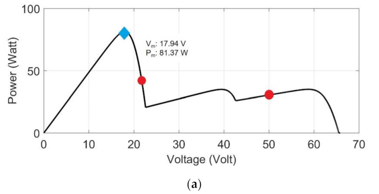
In PS test, all algorithms are tested mainly to find GMPP. The complete data tests are shown in Table 4. Each test has three MPPs which consist of two LMPP and one GMPP. GMPP position is designated at right, middle and left according to Test 4, 5 and 6 respectively. Table 4 shows the GMPP position by power, voltage and duty cycle. Initial particles are located around Dstart range.

4.2.1. Test 4: GMPP at Right Side

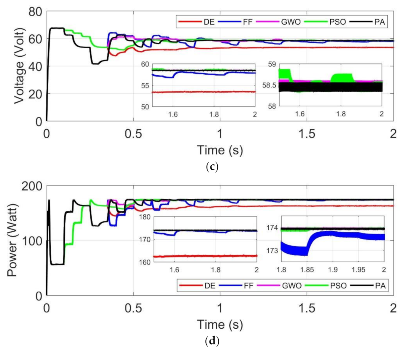
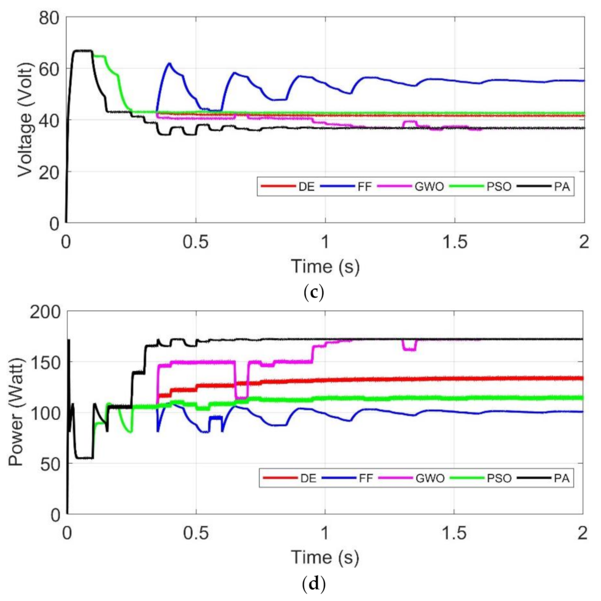
In test 4, GMPP location is between initial particles as shown in Figure 12a. Initial duty cycles are found between 10% and 25%. These duty cycles are equal to operating points of around 55–74 V and 56–161 W. PA algorithm tracks GMPP at t = 0.45 s, followed by FF and PSO at t = 0.5 s, then GWO at t = 0.75 s. DE cannot track the GMPP until the final time of simulation. PA algorithm reaches settling time at t = 0.85 s, followed by GWO at t = 1.35 s. FF algorithm shows the highest power oscillation and continuously oscillates during search. PSO algorithm can track faster than GWO but oscillates and slowly reaches the settling time. It can be seen in zoomed window of Figure 12b–d that PA shows fast tracking without producing unwanted oscillation. At close to t = 2 s, PA, PSO and GWO track GMPP of 173.9 W. FF and DE reach 172 and 162 W. At close to t = 2 s, energy harvesting by PA, GWO, PSO, FF and DE algorithm are 327, 326, 325, 320 and 304 Ws, respectively.

4.2.2. Test 5: GMPP Is Near Initial Particles Location

In test 5, exploration mode of the algorithm is tested. GMPP is outside of initial particles’ range. The initial operating points are around 42–74 V and 56–127 W. As shown in Figure 13a, initial particles are at right side of GMPP. The PA tracks GMPP at t = 0.4 s, followed by GWO at t= 1.1 s. Unfortunately, other algorithms fail to track GMPP. PA has settling time of t = 1 s and GWO t = 1.4 s. The PA tracks GMPP at 171.9 W, as well as GWO. GWO can locate GMPP, but tracks slower than PA. Moreover, GWO generates unwanted power oscillations near GMPP. GWO several times leaves and returns again to GMPP. DE, PSO and FF track at 132, 112 and 100 W, respectively. The PA harvests energy at t =2 s equal to 318 Ws, followed by GWO 296, DE 245, PSO 215 and FF 192 Ws. The PA shows its superiority compared to other algorithms.

4.2.3. Test 6: GMPP Is Far from Initial Positions of Particles

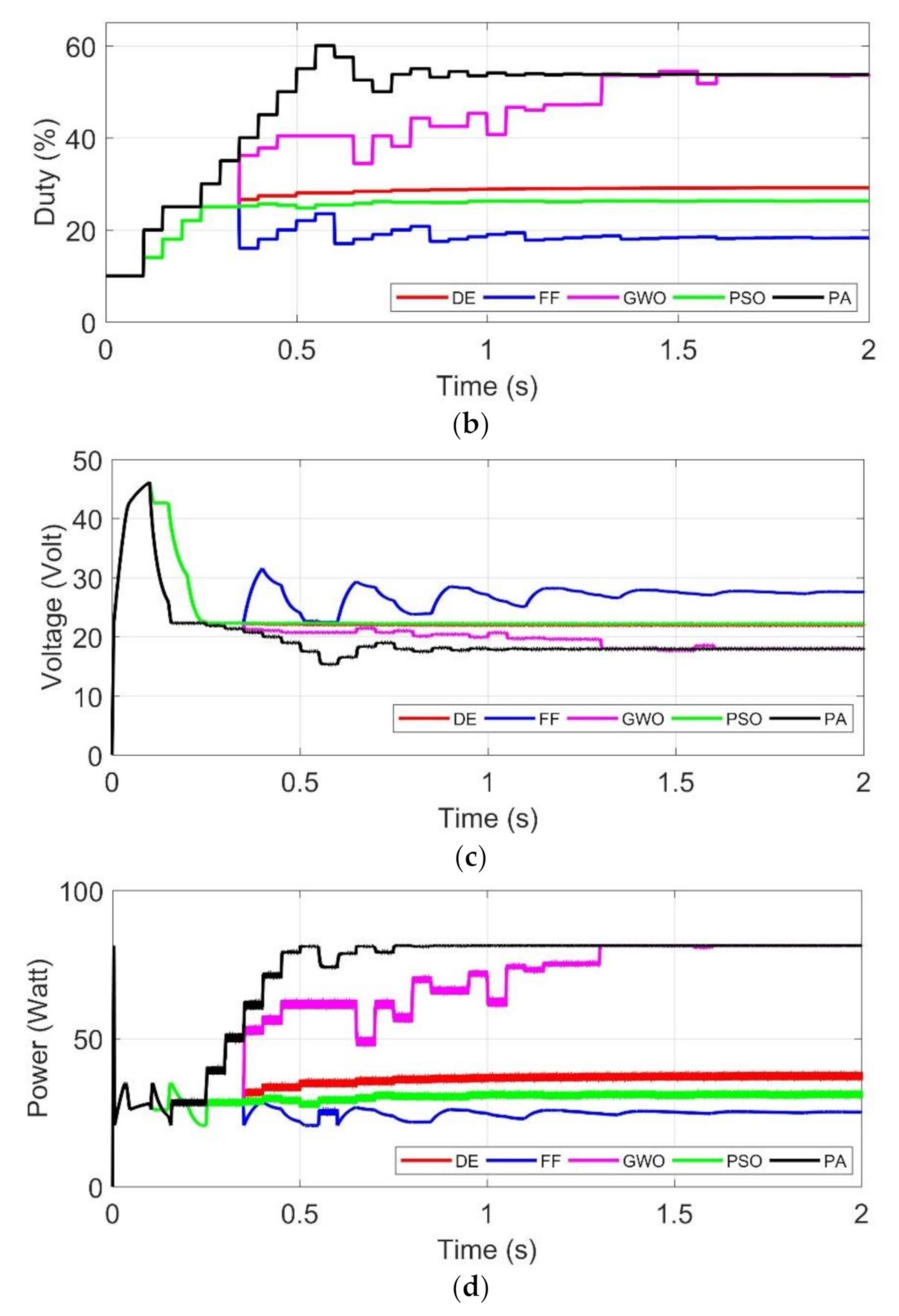
In test 6, GMPP is outside of initial particles’ range. The initial operating points are around 23–46 V and 31–34 W which are shown in Figure 14a. In this test initial particles have similar power value. Note that, MPPT algorithm is based on highest power detection, and so in this situation the algorithm may get confused. PSO and DE are trapped around initial duty cycles. Figure 14b shows that PSO and DE duty cycle are almost constant at 26% and 28% respectively. FF is trapped around duty cycle of 18%. PA and GWO track GMPP successfully. PA track fastest at t = 0.5 s, GWO at t = 1.3 s. PA and GWO reach settling time at t = 0.85 s and t = 1.6 s respectively. Figure 14d shows GWO produces unwanted power oscillation. PA and GWO track GMPP at 81.3 W, while DE, PSO and FF at 36, 30 and 25 W respectively. At t = 2 s, PA harvests the highest energy of 142 Ws, followed by GWO 127, DE 69, PSO 59 and FF 50 Ws. The PA shows its superiority compared to other algorithms.

5. Performance Evaluation

Table 5 shows comparison of testing results 1–6. Each algorithm is tested 10 times for each test 1–6. The results shown in the table is the average value for 2 s. The best performance is indicated by bold fonts. Test 1 shows tracking time between PA and PSO is very close. On the contrary, PA can reach settling time fast but PSO cannot reach convergence at the final time of simulation. PSO employs high random walk to reach MPP, but it also causes leaving and returning to MPP. Metaheuristic algorithm tracking time and settling time are influenced by random walk. If random walk is high, it may help to speed up tracking time but settling time can be longer, and vice versa. Random walk may not help to reach convergence rapidly, especially under condition of initial particles far from MPP/GMPP. Moreover, random walk may produce unwanted duty cycle which may lead to power oscillation. In Test 2, MPP location is close to initial particles. PSO can track the MPP location. However random walk produces random duty cycle which leads to power oscillation. Thereby, PSO harvests lower energy than PA. Additionally PA tracks faster than PSO. In Test 3, exploitation mode is tested. All algorithms can track MPP, but their tracking accuracy results are different. GWO is the fastest tracking time. Additionally, it shows that PA has good exploitation performance. PA algorithm encircles MPP position using particle P1 and P3, and surrounds MPP all the time of iterations. PA algorithm has the lowest settling time, PA algorithm harvests the highest energy compared to other algorithms.
In Test 4, GMPP location is laid between initial particles. Exploitation mode is tested. FF, PSO, GWO and PA can track the GMPP. PSO, GWO and PA track GMPP at power tracking accuracy at around 99%. PA shows the highest energy tracking accuracy, which indicates minimum power oscillation. In Test 5, initial particles are close to the MPP location. Although both PA and GWO can track the GMPP, PA is faster than GWO. Test results confirm fast tracking of PA that energy harvesting by PA is higher than GWO. In Test 6, initial particles have similar power value. It may confuse metaheuristic algorithm which works based on attractiveness of the highest power point. GWO successfully tracks MPP, but its tracking and settling time are reached slowly. Energy harvesting by PA is higher than GWO, confirming that PA performs fast tracking and reaches settling time with minimum oscillation.
It can be concluded that, without involving random calculation, PA has advantages of avoiding unwanted duty cycle which may lead to power oscillations. Exploration and exploitation mode can be done by simple math without random calculation. The ability of exploration helps with the fast tracking. Also, the ability of exploitation mode helps to achieve high accuracy. Automatically variable step size can be done by exploration and exploitation modes. Additionally, high energy harvesting is the combination of high performance of exploration, exploitation, and minimum power oscillation. In terms of overall performance, PA shows superiority among the tested algorithms.

6. Conclusions

In this paper, a new MPPT algorithm is proposed. The performance of proposed algorithm is compared to four existing MPPT algorithms. Six test conditions are used to evaluate the performance of each algorithm. The results show that the proposed algorithm can successfully work under uniform and partial shading conditions. For all tests, the proposed algorithm performs the fastest tracking time and settling time, and the highest power tracking accuracy. Furthermore, the energy tracking accuracy of the proposed algorithm is the highest compared to other tested algorithms. The proposed algorithm overall shows superior performance compared to the DE, FF, PSO and GWO algorithms.

Author Contributions

Conceptualization and Methodology, N.A.W.; Software and Investigation, M.N.H.; Validation, M.Z.E. and T.; Writing-Original Draft Preparation, B.S.; Resources, E.P. and M.Z.E.; Visualization, E.P.; Writing-Review & Editing, T.; All authors have read and agreed to the published version of the manuscript.

Funding

This research received no external funding.

Institutional Review Board Statement

Not applicable.

Informed Consent Statement

Not applicable.

Data Availability Statement

Not applicable.

Conflicts of Interest

The authors declare no conflict of interest.

References

  1. Femia, N.; Giovanni, P.; Giovanni, S.; Massimo, V. A technique for improving P&O MPPT performances of double-stage grid-connected photovoltaic systems. IEEE Trans. Ind. Electron. 2009, 56, 4473–4482. [Google Scholar]
  2. Hung, H.I.; Shih, S.-F.; Hsieh, J.-H.; Hsieh, G.-C. A study of high-frequency photovoltaic pulse charger for lead-acid battery guided by PI-INC MPPT. In Proceedings of the International Conference on Renewable Energy Research and Applications (ICRERA), Nagasaki, Japan, 11–14 November 2012; IEEE: New York, NY, USA, 2012. [Google Scholar]
  3. Luigi, P.; Rizzo, R. Adaptive perturb and observe algorithm for photovoltaic maximum power point tracking. IET Renew. Power Gener. 2010, 4, 317–328. [Google Scholar]
  4. Fathabadi, H. Novel fast dynamic MPPT (maximum power point tracking) technique with the capability of very high accurate power tracking. Energy 2016, 94, 466–475. [Google Scholar] [CrossRef]
  5. Macaulay, J.; Zhou, Z. A fuzzy logical-based variable step size P&O MPPT algorithm for photovoltaic system. Energies 2018, 11, 1340. [Google Scholar]
  6. Alik, R.; Jusoh, A. Modified Perturb and Observe (P&O) with checking algorithm under various solar irradiation. Sol. Energy 2017, 148, 128–139. [Google Scholar]
  7. Tey, K.S.; Mekhilef, S. Modified incremental conductance MPPT algorithm to mitigate inaccurate responses under fast-changing solar irradiation level. Sol. Energy 2014, 101, 333–342. [Google Scholar] [CrossRef]
  8. Teng, J.; Huang, W.; Hsu, T.; Wang, C. Novel and Fast Maximum Power Point Tracking for Photovoltaic Generation. IEEE Trans. Ind. Electron. 2016, 63, 4955–4966. [Google Scholar] [CrossRef]
  9. Mahmoud, Y.; El-Saadany, E.F. Fast Power-Peaks Estimator for Partially Shaded PV Systems. IEEE Trans. Energy Convers. 2016, 31, 206–217. [Google Scholar] [CrossRef]
  10. Moshksar, E.; Ghanbari, T. A model-based algorithm for maximum power point tracking of PV systems using exact analytical solution of single-diode equivalent model. Sol. Energy 2018, 162, 117–131. [Google Scholar] [CrossRef]
  11. Rizzo, S.A.; Scelba, G. ANN based MPPT method for rapidly variable shading conditions. Appl. Energy 2015, 145, 124–132. [Google Scholar] [CrossRef]
  12. Schill, C.; Brachmann, S.; Koehl, M. Impact of soiling on IV-curves and efficiency of PV-modules. Sol. Energy 2015, 112, 259–262. [Google Scholar] [CrossRef]
  13. Ramli, M.A.M.; Prasetyono, E.; Wicaksana, R.W.; Windarko, N.A.; Sedraoui, K.; Al-Turkia, Y.A. On the investigation of photovoltaic output power reduction due to dust accumulation and weather conditions. Renew. Energy 2016, 99, 836–844. [Google Scholar] [CrossRef]
  14. Mamun, M.A.A.; Hasanuzzaman, M.; Selvaraj, J. Experimental investigation of the effect of partial shading on photovoltaic performance. IET Renew. Power Gener. 2017, 11, 912–921. [Google Scholar] [CrossRef]
  15. El-Baz, W.; Tzscheutschler, P.; Wagner, U. Day-ahead probabilistic PV generation forecast for buildings energy management systems. Sol. Energy 2018, 171, 478–490. [Google Scholar] [CrossRef]
  16. Corizzo, R.; Ceci, M.; Japkowicz, N. Anomaly Detection and Repair for Accurate Predictions in Geo-distributed Big Data. Big Data Res. 2019, 16, 18–35. [Google Scholar] [CrossRef]
  17. Ceci, M.; Malerba, R.C.D.; Rashkovska, A. Spatial autocorrelation and entropy for renewable energy forecasting. Data Min. Knowl. Discov. 2019, 33, 698–729. [Google Scholar] [CrossRef]
  18. Udenze, P.; Hu, Y.; Wen, H.; Ye, X.; Ni, K. A Reconfiguration Method for Extracting Maximum Power from Non-Uniform Aging Solar Panels. Energies 2018, 11, 2743. [Google Scholar] [CrossRef] [Green Version]
  19. Chandra, S.; Gaur, P. Radial Basis Function Neural Network Technique for Efficient Maximum Power Point Tracking in Solar Photo-Voltaic System. Procedia Comput. Sci. 2020, 167, 2354–2363. [Google Scholar] [CrossRef]
  20. Pathak, P.K.; Yadav, A.K. Design of battery charging circuit through intelligent MPPT using SPV system. Sol. Energy 2019, 178, 79–89. [Google Scholar] [CrossRef]
  21. Lin, W.; Hong, C.; Chen, C. Neural-Network-Based MPPT Control of a Stand-Alone Hybrid Power Generation System. IEEE Trans. Power Electron. 2011, 26, 3571–3581. [Google Scholar] [CrossRef]
  22. Liu, Y.-H.; Liu, C.-L.; Huang, J.-W.; Chen, J.-H. Neural-network-based maximum power point tracking methods for photovoltaic systems operating under fast changing environments. Sol. Energy 2013, 89, 42–53. [Google Scholar] [CrossRef]
  23. Yilmaz, U.; Kircay, A.; Borekci, S. PV system fuzzy logic MPPT method and PI control as a charge controller. Renew. Sustain. Energy Rev. 2018, 81, 994–1001. [Google Scholar] [CrossRef]
  24. Loukil, K.; Abbes, H.; Abid, H.; Abid, M.; Toumi, A. Design and implementation of reconfigurable MPPT fuzzy controller for photovoltaic systems. Ain Shams Eng. J. 2020, 11, 319–328. [Google Scholar] [CrossRef]
  25. Tang, S.; Sun, Y.; Chen, Y.; Zhao, Y.; Yang, Y.; Szeto, W. An Enhanced MPPT Method Combining Fractional-Order and Fuzzy Logic Control. IEEE J. Photovolt. 2017, 7, 640–650. [Google Scholar] [CrossRef]
  26. Nabipour, M.; Razaz, M.; Seifossadat, S.; Mortazavi, S.S. A new MPPT scheme based on a novel fuzzy approach. Renew. Sustain. Energy Rev. 2017, 74, 1147–1169. [Google Scholar] [CrossRef]
  27. Črepinšek, M.; Liu, S.-H.; Mernik, M. Exploration and exploitation in evolutionary algorithms: A survey. ACM Comput. Surv. 2013, 45, 1–33. [Google Scholar] [CrossRef]
  28. Priyadarshi, N.; Ramachandaramurthy, V.; Padmanaban, S.; Azam, F. An Ant Colony Optimized MPPT for Standalone Hybrid PV-Wind Power System with Single Cuk Converter. Energies 2019, 12, 167. [Google Scholar] [CrossRef] [Green Version]
  29. Titri, S.; Larbes, C.; Youcef-Toumi, K.; Benatchba, K. A new MPPT controller based on the Ant Colony Optimization Algorithm for Photovoltaic Systems under Partial Shading Conditions. Appl. Soft Comput. 2017, 58, 465–479. [Google Scholar] [CrossRef]
  30. Kinattingal, S.; Simon, S.P.; Nayak, P.S.R. MPPT in PV systems using ant colony optimisation with dwindling population. IET Renew. Power Gener. 2020, 14, 1105–1112. [Google Scholar]
  31. Ahmed, J.; Salam, Z. A soft computing MPPT for PV system based on Cuckoo Search algorithm. In Proceedings of the 4th International Conference on Power Engineering, Energy and Electrical Drives, Istanbul, Turkey, 13–17 May 2013; IEEE: New York, NY, USA, 2013. [Google Scholar]
  32. Mosaad, M.I.; El-Raouf, M.O.; Al-Ahmar, M.A.; Banakher, F.A. Maximum Power Point Tracking of PV system Based Cuckoo Search Algorithm; review and comparison. Energy Procedia 2019, 162, 117–126. [Google Scholar] [CrossRef]
  33. Basha, C.H.; Bansal, V.; Rani, C.; Brisilla, R.M.; Odofin, S. Development of Cuckoo Search MPPT Algorithm for Partially Shaded Solar PV SEPIC Converter. In Soft Computing for Problem Solving. Advances in Intelligent Systems and Computing; Springer: Singapore, 2020; pp. 727–736. [Google Scholar]
  34. Sundareswaran, K.; Peddapati, S.; Palani, S. MPPT of PV Systems under Partial Shaded Conditions through a Colony of Flashing Fireflies. IEEE Trans. Energy Convers. 2014, 29, 463–472. [Google Scholar]
  35. Huang, Y.-P.; Ye, C.-E.; Chen, X. A Modified Firefly Algorithm with Rapid Response Maximum Power Point Tracking for Photovoltaic Systems under Partial Shading Conditions. Energies 2018, 11, 2284. [Google Scholar] [CrossRef] [Green Version]
  36. Zhang, M.; Chen, Z.; Wei, L. An Immune Firefly Algorithm for Tracking the Maximum Power Point of PV Array under Partial Shading Conditions. Energies 2019, 12, 3083. [Google Scholar] [CrossRef] [Green Version]
  37. Chaurasia, G.S.; Singh, A.K.; Agrawal, S.; Sharma, N.K. A meta-heuristic firefly algorithm based smart control strategy and analysis of a grid connected hybrid photovoltaic/wind distributed generation system. Sol. Energy 2017, 150, 265–274. [Google Scholar] [CrossRef]
  38. Ebrahim, M.; Osama, A.; Kotb, K.M.; Bendary, F. Whale inspired algorithm based MPPT controllers for grid-connected solar photovoltaic system. Energy Procedia 2019, 162, 77–86. [Google Scholar] [CrossRef]
  39. Qais, M.H.; Hasanien, H.M.; Alghuwainem, S. Enhanced whale optimization algorithm for maximum power point tracking of variable-speed wind generators. Appl. Soft Comput. 2020, 86, 105937. [Google Scholar] [CrossRef]
  40. Tey, K.S.; Mekhilef, S.; Seyedmahmoudian, M.; Horan, B.; Oo, A.T.; Stojcevski, A. Improved Differential Evolution-Based MPPT Algorithm Using SEPIC for PV Systems Under Partial Shading Conditions and Load Variation. IEEE Trans. Ind. Inform. 2018, 14, 4322–4333. [Google Scholar] [CrossRef]
  41. NaimTajuddin, M.F.; Ayob, S.M.; SazliSaad, Z. Evolutionary based maximum power point tracking technique using differential evolution algorithm. Energy Build. 2013, 67, 245–252. [Google Scholar]
  42. Ramli, M.A.; Ishaque, K.; Jawaid, F.; Al-Turki, Y.A.; Salam, Z. A modified differential evolution based maximum power point tracker for photovoltaic system under partial shading condition. Energy Build. 2015, 103, 175–184. [Google Scholar] [CrossRef]
  43. Mohanty, S.; Subudhi, B.; Ray, P.K. A Grey Wolf-Assisted Perturb & Observe MPPT Algorithm for a PV System. IEEE Trans. Energy Convers. 2017, 32, 340–347. [Google Scholar]
  44. Eltamaly, A.M.; Farh, H.M. Dynamic global maximum power point tracking of the PV systems under variant partial shading using hybrid GWO-FLC. Sol. Energy 2019, 177, 306–316. [Google Scholar] [CrossRef]
  45. Mirza, A.F.; Mansoor, M.; Ling, Q.; Yin, B.; Javed, M.Y. A Salp-Swarm Optimization based MPPT technique for harvesting maximum energy from PV systems under partial shading conditions. Energy Convers. Manag. 2020, 209, 112625. [Google Scholar] [CrossRef]
  46. Farh, H.M.H.; Othman, M.F.; Eltamaly, A.M. Maximum power extraction from grid-connected PV system. In Proceedings of the 2017 Saudi Arabia Smart Grid (SASG), Jeddah, Saudi Arabia, 12–14 December 2017; IEEE: New York, NY, USA, 2017. [Google Scholar]
  47. Ram, J.P.; Rajasekar, N. A new robust, mutated and fast tracking LPSO method for solar PV maximum power point tracking under partial shaded conditions. Appl. Energy 2017, 201, 45–59. [Google Scholar]
  48. Eltamaly, A.M.; Al-Saud, M.; Abokhalil, A.G.; Farh, H.M. Simulation and experimental validation of fast adaptive particle swarm optimization strategy for photovoltaic global peak tracker under dynamic partial shading. Energy Rev. 2020, 124, 109719. [Google Scholar] [CrossRef]
  49. Peng, B.; Ho, K.; Liu, Y. A Novel and Fast MPPT Method Suitable for Both Fast Changing and Partially Shaded Conditions. IEEE Trans. Ind. Electron. 2018, 65, 3240–3251. [Google Scholar] [CrossRef]
  50. Mirza, A.F.; Ling, Q.; Javed, M.Y.; Mansoor, M. Novel MPPT techniques for photovoltaic systems under uniform irradiance and Partial shading. Sol. Energy 2019, 184, 628–648. [Google Scholar] [CrossRef]
  51. Shams, I.; Mekhilef, D.S.; Soon, T.K. Maximum Power Point Tracking using Modified Butterfly Optimization Algorithm for Partial Shading, Uniform Shading and Fast Varying Load Conditions. IEEE Trans. Power Electron. 2020. [Google Scholar] [CrossRef]
  52. Kumar, N.; Hussain, I.; Singh, B.; Panigrahi, B.K. Rapid MPPT for Uniformly and Partial Shaded PV System by Using JayaDE Algorithm in Highly Fluctuating Atmospheric Conditions. IEEE Trans. Ind. Inform. 2017, 13, 2406–2416. [Google Scholar] [CrossRef]
  53. Li, L.; Chen, Y.; Liu, H.; Tang, W.; Liu, M.; Wu, J.; Li, Z. A Multi-Producer Group-Search-Optimization Method-Based Maximum-Power-Point-Tracking for Uniform and Partial Shading Condition. IEEE Access 2020, 8, 184688–184696. [Google Scholar] [CrossRef]
  54. Veerasamy, B.; Thelkar, A.R.; Ramu, G.; Takeshita, T. Efficient MPPT control for fast irradiation changes and partial shading conditions on PV systems. In Proceedings of the 2016 IEEE International Conference on Renewable Energy Research and Applications (ICRERA), Birmingham, UK, 20–23 November 2016; IEEE: New York, NY, USA, 2016. [Google Scholar]
  55. Farayola, A.M.; Hasan, A.N.; Ali, A.; Twala, B. Distributive MPPT Approach Using ANFIS and Perturb&Observe Techniques Under Uniform and Partial Shading Conditions. In Artificial Intelligence and Evolutionary Computations in Engineering Systems; Springer: Singapore, 2018; pp. 27–37. [Google Scholar]
  56. Ostadrahimi, A.; Mahmoud, Y. Novel Spline-MPPT Technique for Photovoltaic Systems under Uniform Irradiance and Partial Shading Conditions. IEEE Trans. Sustain. Energy 2021, 12, 524–532. [Google Scholar] [CrossRef]
  57. Rhouma, M.B.; Gastli, A.; Brahim, L.B.; Touati, F.; Benammar, M. A simple method for extracting the parameters of the PV cell single-diode model. Renew. Energy 2017, 113, 885–894. [Google Scholar] [CrossRef]
  58. Patel, H.; Agarwal, V. MATLAB-Based Modeling to Study the Effects of Partial Shading on PV Array Characteristics. IEEE Trans. Energy Convers. 2008, 23, 302–310. [Google Scholar] [CrossRef]
  59. Hart, D.W. Power Electronics; Tata McGraw-Hill Education: New York, NY, USA, 2011. [Google Scholar]
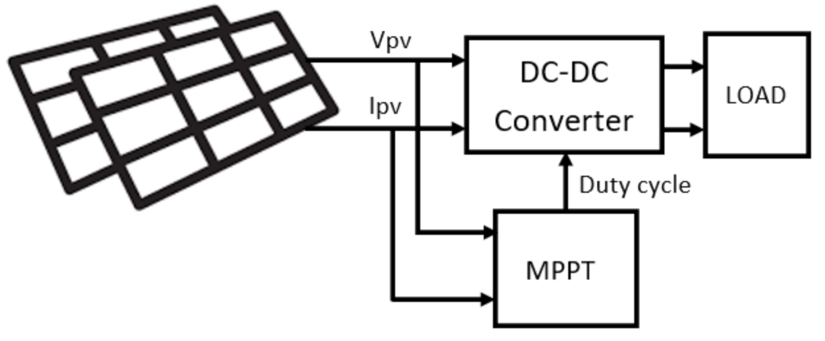
Figure 1. A typical PV Power Generation.
Energies 14 00483 g001
Figure 2. PV cell single diode model.
Energies 14 00483 g002
Figure 3. The Current-Voltage and Power-Voltage characteristics of PV.
Energies 14 00483 g003
Figure 4. Power-Voltage characteristics of PV under PS.
Energies 14 00483 g004
Figure 5. Illustration of algorithm (a) case 1 (b) case 2 (c) and (d) case 3.
Energies 14 00483 g005
Figure 6. Flow chart of proposed algorithm.
Energies 14 00483 g006
Figure 7. The buck converter used to implement the MPPT.
Energies 14 00483 g007
Figure 8. PV Characteristic for uniform irradiance test.
Energies 14 00483 g008
Figure 9. Test 1 (a) Initial particles (b) Duty cycle (%) (c) PV voltage (V) (d) PV power (W).
Energies 14 00483 g009
Figure 10. Test 2 (a) Initial particles (b) Duty cycle (%) (c) PV voltage (V) (d) PV power (W).
Energies 14 00483 g010aEnergies 14 00483 g010b
Figure 11. Test 3 (a) Initial particles (b) Duty cycle (%) (c) PV voltage (V) (d) PV power (W).
Energies 14 00483 g011aEnergies 14 00483 g011b
Figure 12. Test 4 (a) Initial particles (b) Duty cycle (%) (c) PV voltage (V) (d) PV power (W).
Energies 14 00483 g012aEnergies 14 00483 g012b
Figure 13. Test 5 (a) Initial particles (b) Duty cycle (%) (c) PV voltage (V) (d) PV power (W).
Energies 14 00483 g013aEnergies 14 00483 g013b
Figure 14. Test 6 (a) Initial particles (b) Duty cycle (%) (c) PV voltage (V) (d) PV power (W).
Energies 14 00483 g014aEnergies 14 00483 g014b
Table 1. Comparison between issues and key contributions.
No.Identified Existing Issues from the LiteratureThe Key Contributions of the Proposed Algorithm
1.
Complex algorithm
High computational iteration
Consumes significant computational power and large memory size
Simple math algorithm to reduce computational load
2.
Exploration and exploitation mode involving random walk/variables
Exploration and exploitation mode using simple math
3.
Away from the MPP
Inconsistencies tracking speed
Prolonged unstable starting period
Evaluation after all particles deployed
Fast tracking by evaluating progress for every single executed particle/duty cycle
4.
Power fluctuations
Unwanted fluctuations
Power oscillations by random walk
Random variables
Jumping duty cycle
Without involving random step to prevent power fluctuations, mainly in convergence
5.
Lower accuracy/ Premature convergence by:
  • Locking best solution in metaheuristic algorithms
  • Fixed step in conventional MPPT
Smooth variable steps to increase accuracy in exploitation mode
Table 2. PV panel specifications.
No.ParametersVariableValue
1.Number of Cells N s 36
2.Maximum PowerPm100 W
3.Voltage at PmVm17.6 V
4.Current at PmIm5.69 A
5.Open-Circuit VoltageVoc22.6 V
6.Short-Circuit Current I s c 6.09 A
7.Shunt Resistance R P 134.0754 Ohm
8.Series Resistance R s 0.286 Ohm
9.Light Intensity S 0 1000 W/m2
10.Ambient Temperature T 25 °C
11.Diode saturation current I s o 8.99 × 10⁻⁹ A
12.Ideality factor A 1.25052
13.Temperature coefficient C t 0.003958 A/°C
14.Bandgap energy N s 1.12 eV
Table 3. Buck Converter specifications.
No.Component/ParameterLabelValue
1Switching frequency f 10 kHz
2Inductor L f 87 µH
3Capacitor C f 43 µF
4Load resistor R 1.2 Ω
Table 4. Partial Shading Tests.
CaseIrradiance (W/m2)GMPPDstart
TestPV1PV2PV3PositionPm (W)Vm (V)Dm (%)D1 to Dn (%)
41000500700Right173.9 W58.6 V23%10 to 25%
51000800300Middle171.9 W36.9 V37%10 to 25%
6100150800Left81.3 W17.9 V53%10 to 25%
Table 5. Comparison of test results.
Test NO/AlgorithmTracking Time (s)Settling Time (s)Power Tracking (W)Power Tracking Acc. (%)Energy Harvesting (Ws)Energy Tracking Acc (%)
Test 1 300.0100.00600.0100.00
DE--76.725.57146.824.47
FF--76.525.5072.712.12
PSO0.44-299.999.97382.263.70
GWO--92.330.77169.628.27
PA0.390.79299.999.97523.687.27
Test 2 300.0100.000600.0100.00
DE--256.785.57466.577.75
FF--84.528.17213.235.53
PSO1.111.72299.999.97521.786.95
GWO--286.795.57477.579.58
PA0.610.82299.999.97550.791.78
Test 3 300.0100.00600.0100.00
DE--295.798.57570.695.10
FF1.19-299.999.97568.194.68
PSO1.011.92299.999.97570.695.10
GWO0.601.62298.599.50572.495.40
PA0.611.11299.999.97573.495.57
Test 4 173.9100.00347.8100.00
DE--163.493.96305.187.72
FF0.49-171.798.73322.292.64
PSO0.51-172.399.08324.393.24
GWO0.771.36172.999.42326.493.85
PA0.450.85172.999.42327.394.11
Test 5 171.9100.00343.8100.00
DE--133.277.49244.571.12
FF--103.260.03191.455.67
PSO--113.666.08216.462.94
GWO1.121.72170.999.42298.386.77
PA0.411.02170.999.42316.792.12
Test 6 81.3100.00162.6100.00
DE--35.743.9170.243.17
FF--24.830.5051.331.55
PSO--31.238.3860.136.96
GWO1.311.6280.999.51128.378.91
PA0.520.8780.999.51140.386.29
Publisher’s Note: MDPI stays neutral with regard to jurisdictional claims in published maps and institutional affiliations.