1. Introduction
The aim of the research is to verify the feasibility of an on-the-road prototype of a power train for a hybrid propulsion vehicle. The specific task consists of the study and implementation of an innovative supercharging machine for the 900 cc ICE of a city car. Our proposal is to mechanically disconnect the compressor/turbine complex, supporting the rotation of the C compressor with a dedicated electric motor and creating a T turbine connected to a generator. Mechanical decoupling C/T allows both machines to be designed so that they operate close to the maximum efficiency point for most of the expected real operating range. Specifically, the turbine will have a slightly lower rotational speed than that of the original group and will therefore be slightly larger in size. The advantage is that in current supercharging groups the surplus at high revs is discharged through the wastegate valve without expanding into the turbine. In the configuration proposed here, however, all the energy of the flue gases is used by the turbine to generate electrical power that can be used where required. The actions taken were:
Study of an appropriate configuration of a new supercharging unit for the specific thermal engine chosen here (Smart 900 turbo ≈ 66 kW), separating the compressor and the turbine and creating the two devices with ad hoc components;
Simulation of the behavior of the new group over the entire operating range of the engine, possibly making appropriate changes to the configuration originally chosen;
Design and implementation of a prototype configuration of the new Compressor and Turbine group;
Performance of experimental analysis on the test bench to calibrate the prototype and make any improvements.
In this regard, it is worth mentioning the system called eBooster [
1] consisting of a centrifugal compressor not dragged by the turbine driven by exhaust gases but by a 48-Volt electric motor. Decoupling allows the management of the air flow rate at the compressor and cylinder inlet regardless of the rotation speed and operating conditions of the engine, and in addition minimizes turbo-lag, improving the response to transients. The eBooster system, driven by a brushless DC motor, with highly heat-resistant permanent magnets, is a compact unit characterized by low inertia and low mechanical and electrical losses, since it is not connected to the exhaust gases for the drive. Some authors have investigated the coupling between electric motor and turbocharger, studying the behavior of engines up to 160,000 rpm [
2], supplying a few data, and the optimal configuration of the electric device [
3,
4] for the hybrid configuration. In the case of electric motors, the choice is dependent on the application and the various constraints, especially dimensional.
Furthermore, its flexibility guarantees the increase in the boost pressure and the improvement of the transient behavior, without increasing the back pressure of the exhaust gases and without impact on the charge replacement in the cylinder. It is no coincidence that the studies conducted [
5] have highlighted the ability of the system to be “bidirectional” (from an energy point of view), but limiting the studies conducted to a heavy-duty diesel engine and never exceeding the speed of 2000 rpm of the ICE engine. Other authors have investigated the possibility of equipping an ICE diesel with a regenerative turbocharger [
6] by simulating its behavior on the FTP-75 drive cycle and evaluating the performance of the system. In fact, the electrical energy of the 48-Volt system, stored in a battery pack, used to operate the eBooster, is largely produced through regeneration. Moreover, it has been studied how it “could” be possible to reduce consumption and pumping losses [
7] through the recirculation of exhaust gases and how this affects the electrical system. In addition, it has been evaluated that electric turbocharging is a challenging solution and can increase the efficiency of the vehicle [
8].
Despite all the studies conducted, the solution that is adopted and that has given excellent results is a configuration—compressor side—where the current dimensions of the eBooster system are a total length of only 170 mm (including the compressor inlet flange) and a diameter of 135 mm. With such dimensions, the actual devices guarantee a speed of 70,000 rpm.
In this case study, such limits are exceeded. In fact, through simulations and previous experiences, it has been possible to study, simulate, realize, and test the direct coupling between compressor and a high speeds electric motor (above 210,000 rpm, higher than the actual 70,000 eBooster rpm or 160,000 of [
2]) with high efficiency and very compact dimensions. In addition, to create the prototype with most of the commercial components, the interesting and “new” modification was to redesign ad hoc only the shaft the compressor using the same compressor wheel, which is currently installed in the car.
The energy losses for coupling and the efficiency of the system were verified and measured experimentally. The obtained results are, on 5000 W of installed power, about 750 W, so divided: the power lost by the driver is about 250 Watts, while the engine loses are about 5% of the installed power. The various data available on the eBoosters deliver a “black box” product from the various manufacturers. Here it is described how to make it, with all the operative characteristics, using a commercial compressor and high-tech electric motor.
To conclude, the energy flows will be evaluated only when the turbine and its generator will also be installed. In fact, then will it be it is possible to make a comparison between experimental data and simulations and fully highlight the novelty of the system.
Last but not the least, the novelty of this work is the direct coupling between the compressor and the electric motor at a speed that is three times higher than that of the current installed and operating eBooster (about 200,000 rpm) declared and verified by Commercial Firms and Enterprises. The tests carried out are aimed at verifying the reliability of such a particular coupling (certainly innovative, since it is even “patent pending”) and the design procedure, simulation process and construction of the device. Finally, with these characteristic operative conditions, the verification and validation of the performance of the direct coupling and of electric motor is “quite new”, since there is no data on couplings at these speeds.
2. Compressor Characteristics
Once the motorization of the city car (999 cc) has been established, the existing group on the vehicle has been identified and the operational map of the compressor is reported. The next step is to perform a preliminary sizing of the considered machine. Design means, strictly speaking, defining all its dimensions and shape relationships, choosing the materials with which to make it, and arriving at a constructive design. The problems posed by the choice of materials will be dealt with later, during the FEA simulations. The discussion will be the classic quasi-one-dimensional procedure. The midspan section is usually referred to, but for obvious reasons, the hub and tip sections will also have to be considered (the compressor is radial,
Figure 1 and
Figure 2).
The main hypotheses are [
9,
10]:
constant speed in the inlet section or—if the pre-rotation is adopted—a law Vt = f(r) is known;
the motion takes place in fixed channels for cylindrical streamline and mobile channels for helical ones;
the speed is constant on the delivery section.
Once the design procedure has been carried out, the following values (
Table 1) of the main kinematic and geometric parameters of the turbomachine are obtained.
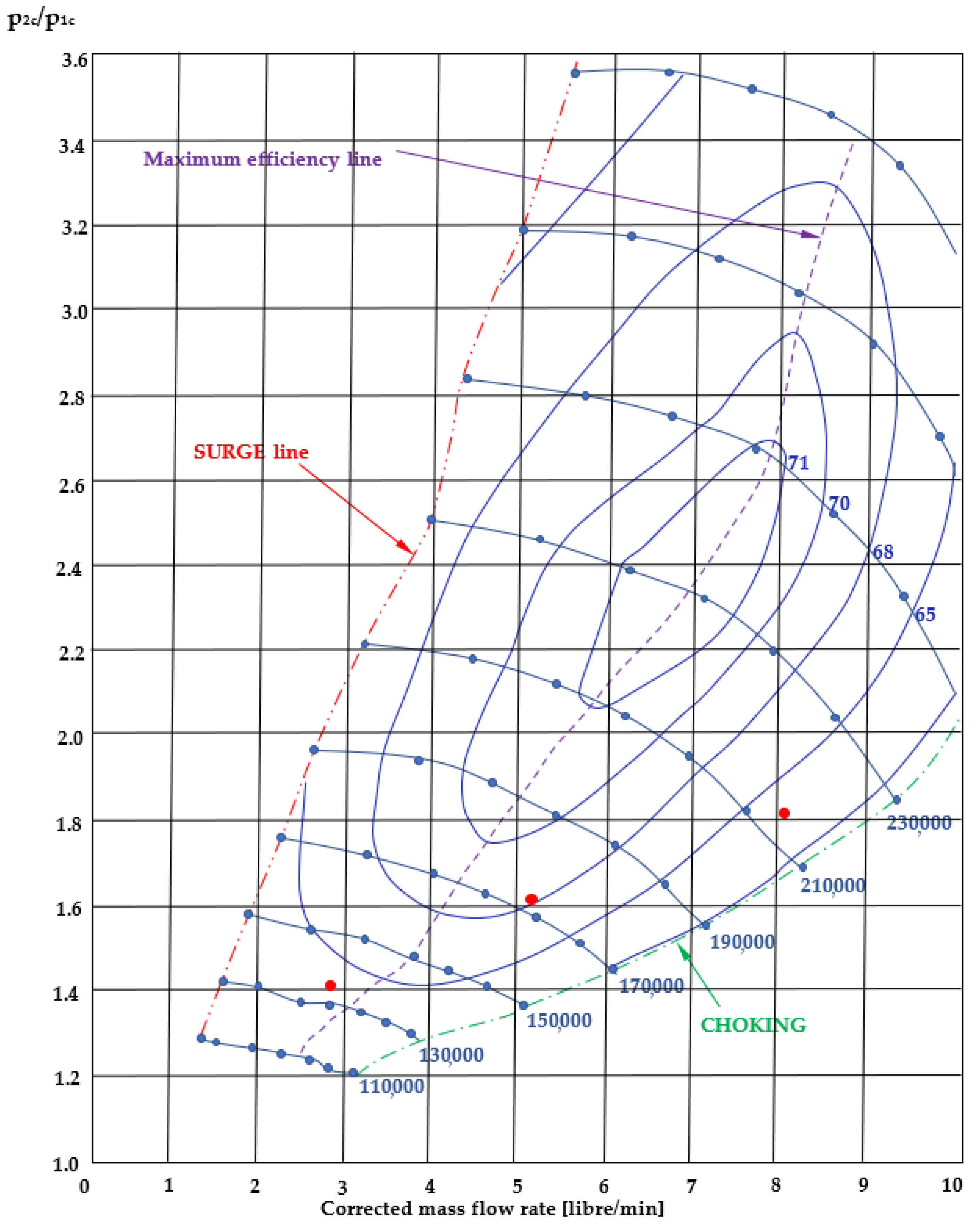
From the data analysis, it is possible to confirm the correspondence with the existing model of the turbocharger, installed in the reference vehicle. The operating points of the compressor were then evaluated at the various rotational speeds of the ICE engine (all data are provided by the firm, but are under confidential restrictions), and using the previous map (
Figure 1). Then, once the map of the engine and compressor are known, established various rotational speeds of the ICE engine [
11], it was possible to compile
Table 2 and report according to the ICE speed, the power required by the compressor, for its correct operation. In
Figure 1 are reported the actual operating points of the compressor, while in
Figure 3 the corresponding required power.
3. Compressor Electrification Design Procedure
The innovative aspect lies in the direct coupling with the electric motor. In fact, the turbomachinery for supercharging is not coupled with electrical components, due to the high speeds achieved. In this case, an electric motor was designed and manufactured that could directly connect with the compressor, and provide the necessary power required by the compressor for its proper operation inside the vehicle. Regarding the energy balance of the coupling, the manufacturer provides the following data: the power lost by the driver is about 250 Watts. However, the engine loses about 5% of the installed power. Therefore, for a power of 5 kW the lost power is about 500 Watts. For a total of 750 Watts. In this way, the research aims to decouple the turbocharger group and build two distinct systems. A system composed of the compressor C and an electric motor EM to achieve air compression to be delivered into the combustion chamber. In addition, a second system consisting of the turbine T and an electric generator EG.
After several analyses, it was decided to use as many of the existing commercial components as possible—in this case, the compressor wheel, its lubrication system, and the volute. Since the intent is to directly link the electric motor with the compressor, it was, therefore, necessary to design the shaft from scratch. In this configuration, the shaft of the electric motor and compressor is the same. It was necessary to redesign the shaft and then submit it to a modal–structural FEA simulation to analyze any displacements and resonance frequencies.
Shaft Drawing and Material Selection
SolidEdge, a 2D/3D hybrid design software, was used for shaft modeling. The chosen configuration derives from the requests of the manufacturer. A representation of the electric motor was provided, according to the requests, which allowed modeling of the part of the shaft inside the engine [
12,
13,
14]. The figure below (
Figure 4) presents the first configuration of the electric motor, subsequently built. Thanks to these indications, it was possible to realize the shaft (
Figure 5) and then simulate it. Concerning the material, the device has been made of Inconel, which, thanks to its characteristics, is suitable for the specifications to be respected. INCONEL
® nickel–chrome alloy 625 (UNS N06625/W.Nr. 2.4856) is used for its high strength, excellent fabricability, and exceptional corrosion resistance.
Operating temperatures range from cryogenic ones to 1800°F (982 °C). The resistance of the INCONEL 625 alloy derives from the stiffening effect of molybdenum and niobium on its nickel–chromium matrix; therefore, no hardening treatments are required for precipitation. This combination of elements is also responsible for a resistance superior to a wide range of corrosive environments of unusual gravity as well as high-temperature effects such as oxidation and carburation. The properties of the INCONEL 625 alloy make this an excellent choice.
4. Shaft Simulation
The program used for structural analysis is NASTRAN sol101, while NASTRAN sol103 was used for the modal analysis. The shaft has been discretized with hexa8 elements (8 nodes) with the subdivision into 208,897 elements and 218,730 nodes (
Figure 6). To simulate the presence of the electric motor rotor and compressor wheel, rbe3 elements (orange in
Figure 7) were used, in which nodes there is a 0D concentrated conm2 element that has the mass and inertia properties [
15,
16] of the objects it represents (in orange in
Figure 8).
Table 3 shows the rotor data subsequently produced, while
Table 4 the compressor ones.
For structural analysis, the following were considered:
As radial constraints on nodes (
Figure 8):
- 1.
Bushings resting on the central body of the bearing
- 2.
The radial bearing of the engine
As an axial constraint (
Figure 9): The engine
As a constraint to torque (
Figure 10): The engine
For modal analysis, the torsion constraint represented by the engine was removed but an axial constraint was added on x at the central body and the compressor rotor (
Figure 11)
The load on the rotor thread was considered, imagining splitting the total load and distributing it to individual nodes (
Figure 12).
Based on the radius and torque, derived from the known data on rotational speed and power, the load was calculated and for the calculation on the individual nodes, the load was then divided by the total of 1080 knots (see
Table 5).
Preload, calculated with an empirical formula, resulting from the action of the current and central body, has also been considered (
Table 6 and
Figure 13), focusing on threading (1080 knots) and spacer (240 knots).
Finally, the gravity and action of the centrifugal force acting on the shaft were also considered to be a load.
4.1. Results: Structural Analysis
The study has been concentrated in terms of stress (calculated with von Mises’s criterion) and deformation (in terms of global displacement as the vector sum of node displacement vectors). The results obtained show, based on the three considered speeds (145,000, 180,000, 210,000 rpm), very low-stress levels, which do not require in-depth studies or structural or dimensional changes. The following images (
Figure 14a–c) show stress levels in the three cases.
The most solicited area is located near the spacer between the electric motor and the central lubrication body. The extreme values reached are reported in
Table 7.
The study of deformation, shown in orange in the figure, shows that the main effects are due to the torque moment at the engine and on the spacer, but it is emphasized that this deformation has very low levels and is not worrying for the realization of the shaft (
Figure 15).
Below are the graphs (
Figure 16a–c) showing total displacements as the vector sum of displacement vectors in the 3 directions. In
Table 8 are reported the results.
4.2. Results: Modal Analysis
For modal analysis, 30 ways were considered (
Table 9)
The frequencies of interest—in this case—are:
2417 Hz @ 145,000 rpm
3000 Hz @ 180,000 rpm
3500 Hz @ 210,000 rpm
Finally,
Figure 17a shows the bending mode, where the deformation is concentrated near the engine rotor. The engine was considered to be mass and inertia but was neglected in terms of stiffness, as suggested by the manufacturer.
Figure 17b shows the behavior of the 3rd bending mode, in which the deformation concentrates near the compressor rotor.
In conclusion, it can be affirmed that the dimensions used for the shaft are satisfactory in terms of stress, deformation, and displacement, as no abnormal or near-breaking value has been found. In fact, from the analysis of results, the most considerable, but not significant, deformation occurs at 210,000 rpm at the compressor rotor. Furthermore, the most relevant stress value is at 210,000 rpm, but this time at the spacer. The maximum value reached is not dangerous for the operating conditions.
5. Experimental Campaign Test
Once designed, the shaft was made and inserted into the electric motor. Finally, the compressor, with its volute and its lubrication system was inserted. All the components were thus assembled, and it was studied how to realize the test bench. For its realization, it is necessary to remove the turbocharger group shaft. Once the shaft has been removed, the new one is adopted, to directly connect the compressor with the electric motor. It was decided to maintain the existing lubrication system (oil) and to create an external circuit for the recirculation of the lubricant for the bench. Below, in
Figure 18, is the “concept” of the realized test bench. In the assembling, two pressure gauges (P) are used for the evaluation of the pressure ratio β, 2 thermocouples (T) for the measurement of the compressor inlet and outlet temperature, and finally of a current clamp (A) for the measurement of the electrical power provided by the engine and absorbed by the compressor. Finally, there is an 8–10 channel multimeter for recording the various measurements. The test bench can measure:
- (1)
delivered/absorbed power;
- (2)
compressor input and output pressures;
- (3)
compressor input and output temperatures.
The final step was to propose a test procedure that can be easily executed and repeated.
5.1. Test Procedure
It is planned to vary the speed from the acceptable minimum of 10,000 rpm to the maximum set of 210,000 rpm, with a step varying between 10,000 and 30,000 rpm.
The procedure adopted is listed below:
- (1)
Electric motor (EM) startup
- (2)
Pump (P) startup
- (3)
Set the minimum speed by PC
- (4)
Achieving stationary conditions (about 2 min)
- (5)
Measurement of pressure, temperature, and power delivered by the EM
- (6)
Differential speed increase until maximum speed is reached
- (7)
Point 3–4–5 shall apply for each step
- (8)
Speed reduction to minimum speed (gradually)
- (9)
Switch off the electric motor
- (10)
Switch off the pump.
- (11)
Collect data via PC
5.2. Data Collection and Post-Processing
The campaign will be conducted, adopting the following procedures:
- (1)
Environmental parameters
The temperature of the external environment will be monitored every 15 min during testing. A classic bulb thermometer (sensitivity of 0.5 degrees centigrade, error of 0.2 degrees centigrade) can be used.
- (2)
Nameplate of the instruments used
- 1.
Thermocouple SE011 PT100, Class A. Temperature range −30 + 150 °C, accuracy ±0.15 °C at 0 °C. Stainless probe, cable connected;
- 2.
Bourdon EN 837-1 (ASME B40.100) pressure gauge. Scale range 0.1–5 bar, accuracy class ±2.5% of span. Working Pressure: Steady 3/4 of full-scale value, Fluctuating 2/3 of full-scale value, short-time full-scale value. Operating Temperature: Ambient 20 °C to + 60 °C, Medium +60 °C;
- 3.
Multimeter RS PRO RSDM3055A, 750V ca, 10A ca, CAT I/II, True RMS. Voltage DC: 200 mV~1000 V, Current DC: 200 μA~10 A; Voltage AC: 200 mV~750 V, Current AC: 20 mA~10 A. Resistance: 200 Ω~100 MΩ, Capacity: 2 nF~10000 μF. Frequency range: 20 Hz~1 MHz, Step time: 1 μs~0.05 s.
- (3)
Pre-processing and data standardization
All data are collected via PC and then processed as follows [
17,
18,
19,
20]:
Gaussian analysis of deviations: mean values, mode, median, and standard deviation are calculated automatically by the acquisition card software;
Filtering: any data that has exceeded 3σ will be individually checked and considered to be spurious if any acquisition errors have not been found;
Standardization: the values are standardized to check that their distribution follows a Gaussian one.
All data are collected and reported in tables and graphs. Sensitivity analysis is evaluated.
5.3. The Test Results
After assembling the device (
Figure 19) the system was connected to the various instruments and the testing campaign began. Following the procedure described above, a test campaign was conducted on several days and 3 times a day, for a total of operating hours of about 30 h per week, with stations of 2 continuous hours. Currently, we have been working for at least 4 weeks, managing to total of 120 h of operation. The results obtained are reported according to the speed of rotation of the electric motor.
Table 10 compares all actual obtained values.
In addition, the following graphs report the trend of the delivered power and the compression ratio (
Figure 20,
Figure 21 and
Figure 22). About sensitivity analysis, since the fundamental parameter is the speed of rotation, it was not necessary to implement it, as it has already been explicitly inserted in the representations shown.
Finally, it has been experimentally verified that the coupling studied has an efficiency of about 87% that is very close to that declared by the manufacturer of about 90%.
6. Final Remarks and Conclusions
A very important and “innovative” aspect was the possibility of creating, as part of the electrification process of the power train for the mild hybrid, a “direct coupling” between the electric motor and compressor. All these are thanks to the design of a new electric motor, operating at high rotational speeds, which are characteristics of turbomachinery.
The present work focuses on two aspects. The first is the shaft/device design and the other the experimental validation of the proposed solution. These two aspects are interconnected, as the design; the aspect necessary to realize the device was then validated by experimental tests. From a design point of view, the decision to replace the entire shaft of the turbocharger group and to replace it with one made “ad hoc” and from Inconel material, was completely positive. The test campaign demonstrated the robustness and reliability of the built device.
Concerning the test campaign, the tests showed a close correspondence with the theoretical values previously obtained. It was possible to reproduce the trend of the device’s characteristic parameters, also with additional information. To improve the test campaign, in the short term, a flow meter is planned to be introduced to evaluate the actual processed mass flow rate. In addition, it will be possible to “redraw” the operating map of the compressor.
The next and final step will be to redesign the turbine (now separated from the compressor). The author is confident that this component will be less problematic than the compressor. The turbine can now use all the enthalpy drop of the ICE exhaust gases and will be larger and operate at lower speeds. As a result, the connected electrical equipment will also be less complicated, compared to that designed and built for the compressor.


