Article

Thermodynamic Analysis of the Effect of Green Hydrogen Addition to a Fuel Mixture on the Steam Methane Reforming Process

by
Robert Kaczmarczyk
Department of Fundamental Research in Energy Engineering, Faculty of Energy and Fuels, AGH University of Science and Technology, Al. Mickiewicza 30, 30-059 Krakow, Poland
Energies 2021, 14(20), 6564; https://doi.org/10.3390/en14206564
Submission received: 1 September 2021 / Revised: 4 October 2021 / Accepted: 8 October 2021 / Published: 12 October 2021
(This article belongs to the Section A5: Hydrogen Energy)

Abstract

:
Steam methane (CH4–H2O) reforming in the presence of a catalyst, usually nickel, is the most common technology for generating synthesis gas as a feedstock in chemical synthesis and a source of pure H2 and CO. What is essential from the perspective of further gas use is the parameter describing a ratio of equilibrium concentration of hydrogen to carbon monoxide ( H / C = x H 2 / x C O ) . The parameter is determined by operating temperature and the initial ratio of steam concentration to methane S C = x H 2 O 0 / x C H 4 0 . In this paper, the author presents a thermodynamic analysis of the effect of green hydrogen addition to a fuel mixture on the steam methane reforming process of gaseous phase (CH4/H2)–H2O. The thermodynamic analysis of conversion of hydrogen-enriched methane (CH4/H2)–H2O has been performed using parametric equation formalism, allowing for determining the equilibrium composition of the process in progress. A thermodynamic condition of carbon precipitation in methane reforming (CH4/H2) with the gaseous phase of H2O has been interpreted. The ranges of substrate concentrations creating carbon deposition for temperature T = 1000 K have been determined, based on the technologies used. The results obtained can serve as a model basis for describing the properties of steam reforming of methane and hydrogen mixture (CH4/H2)–H2O.

1. Introduction

In gas-fired power generation, commonly used energy carriers include mixtures of hydrocarbons, with methane being one of the components. Over the recent years, attempts have been made to also use hydrogen as an energy carrier. Global utilization of the potential of renewable energy sources and efforts to find cleaner energy sources contribute to interest in hydrogen as an alternative to traditional liquid and gaseous fuels. In recent years there has been an increasing interest in hydrogen production by water electrolysis using electricity obtained from renewable sources. Power-to-gas technology is an innovative solution providing new opportunities for grid balancing. Electricity surpluses from renewable sources can be used to produce hydrogen which, in turn, can be injected into the gas grid in order to store the chemical energy of hydrogen. A conceptual framework and a review of pilot power-to-gas plants operated in various countries are presented in [1,2]. The technological aspects of the integration of the power grid and gas grid for the purpose of storing surpluses of electricity as gas produced from renewable sources (wind farms and solar power plants) using technology for injection of hydrogen from power-to-gas plants to the gas grid are compared in [3,4,5,6,7,8,9,10,11]. Permitted quantities of hydrogen in the gas grid are determined by energy consumers’ technical and technological preferences, the grid structure as well as composition and volume flux of gas. The prospect of laying autonomous pipeline networks for transporting hydrogen in 100% concentration adds costs to planned capital projects spread over time. That is why using the existing natural gas pipelines is an alternative solution for transport of hydrogen. In methane pipeline networks, hydrogen concentration in the range up to 20% volume fraction is considered stable. Steam reforming of natural gas in the presence of a nickel catalyst, in the 700–1100 °C temperature range is currently the cheapest and technologically most common method of hydrogen production. Steam reforming can be used to produce hydrogen also from hydrocarbons higher than methane i.e., from ethane, propane-butane and higher ones [12,13,14].
The steam reforming of methane (SRM) stands out with the largest H2 output compared to other known methods, because the water—which is an oxidant—contains hydrogen ions. However, the side effect of CO2 emission in SRM is a major problem [15,16]. Another major problem encountered during methane conversion is carbon deposition on a catalyst [17]. This phenomenon worsens the catalytic activity. For environmental reasons, the dry reforming of methane (DRM) presents a great advantage, because of involved raw materials: methane and carbon dioxide. However, high endothermicity leads to high costs associated with providing the appropriate amount of energy necessary to heat up the system. In recent years, extensive research has been conducted to obtain DRM catalysts showing high activity at lower temperatures [18,19,20]. Another solution that allows reducing the costs of providing thermal energy to the system is the use of solar energy [21,22]. Solar energy can also be used to activate the catalyst in a process of photocatalysis—it has been shown that CO2 could be transformed into hydrocarbons when it is in contact with water vapor and catalysts under UV irradiation. This paper [23] presents an experimental set-up to study the process employing a new approach of heterogeneous photocatalysis using pellet catalysts instead of immobilized catalysts on solid substrates. The most widely used and described photocatalysts contain a semiconductor which is titanium dioxide (TiO2) [24,25]. Yoshida et al. used platinum catalyst on TiO2 support and performed steam reforming of methane [26]. As a result, only trace amounts of carbon monoxide were observed, and the ratio of H2/CO2 was close to four. Yoshida et al. also reported that SRM could be driven by irradiating light on Pt-loaded La-doped NaTaO3 at room temperature [27]. László et al. performed photocatalytic dry reforming of methane using titanate nanotubes that were modified with gold and ruthenium [28]. Cho et al. [29] discusses recent advances in methane photocatalytic reforming to provide different reforming strategies. The combination of photocatalytic methods and traditional thermal catalysis may allow the efficient use of renewable energy and the utilization of major greenhouse gases. However, the design of a catalyst with high activity and stability in the methane reforming process is still a challenge and the subject of numerous research studies. A steam reforming of biomass gasification products was recently found to be a promising method of green hydrogen production that has the potential to reduced greenhouse gas emissions [30,31,32]. Moreover, the process can effectively be conducted using the nickel-based catalyst with high resistance to coke formation [33]. The reforming reactor can be coupled with solid oxide fuel cells for various fuel compositions [34]. The miniaturization of steam reformers, caused by the application in a combined system with fuel cells, urges rethinking the design of the reactors [35]. The used catalyst inhibits or exhibits carbon formation, but the process’s direction, and if it is favorable to occur, can be provided by thermodynamic analysis. Consequently, thermodynamical analysis is of special significance for such small-scale reactors and needs to be carried out in any theoretical or experimental study.
In the most advanced countries in the world, steam reforming accounts for up to 95% of hydrogen production. Therefore, in the technologies market, a specific countertendency can be seen—hydrogen as a product of chemical reactions if steam methane reforming and hydrogen as a substrate in mixture (CH4–H2) brought into the reforming process. This fact can be expressed as follows:
( C H 4 / H 2 ) H 2 O T ,   N i ( H 2 , C O , C O 2 , H 2 O , C H 4 )
The problem of the effect of hydrogen (from renewable energy sources) contained in methane on the steam reforming of gaseous phase (CH4/H2) is interesting both in the cognitive and application aspect. In this paper, by means of thermodynamic analysis an equilibrium composition and a range of concentrations of substrates involved in carbon deposition in the steam reforming of hydrogen-enriched methane (CH4/H2) have been determined. A thermodynamic analysis of conversion of hydrogen-enriched methane (CH4/H2)–H2O has been carried out for temperature of T = 1000 K, equivalent to the industrial process conditions. The results obtained can serve as a model basis for describing the properties of steam reforming of methane and hydrogen mixture (CH4/H2)–H2O.

2. Thermodynamic Analysis

The thermodynamic analysis of conversion of hydrogen-enriched methane (CH4/H2)–H2O has been performed using parametric equation formalism, allowing for determining the equilibrium composition of the process [36,37,38,39,40]. According to this concept, for any chemical reaction involving reagents (Ai) characterized by the equation:
i = 1 s k i A i = 0 ,   i = 1 ,   2 ,   3 , , s
We assume positive values of stoichiometric coefficients (ki) in respect of products, negative values for substrates, and the value of zero for reagents not involved in the chemical reaction. Under isobaric and isothermal conditions, the composition of the gaseous phase of a reaction change along a straight line, and the transition of reagents from the initial state to the final state (equilibrium state) can be marked with a vector parallel to the straight line. For a s-dimensional space (where: s—number of reagents) a parametric equation of a straight line can be written as:
x i = x i 0 + τ c o s α i ,   i = 1 ,   2 ,   3 , , s
where: x i , x i 0 —equilibrium and initial mole fraction of component i, α i —direction angle of vector, τ—straight line parameter, τ R .
An expression for direction cosine takes on the following form:
c o s α i = k i x i 0 i = 1 s k i i = 1 s ( k i x i 0 i = 1 s k i ) 2 ,   i = 1 ,   2 ,   3 , , s
where: ki—stoichiometric coefficient of reagent i.
Direction cosines of the vector are not time dependent; they are the functions of the initial composition and of reaction stoichiometric coefficients. In the case of reaction ( i = 1 s k i 0 ) , a change in the composition of a phase occurs along straight lines intersecting at the so-called “characteristic point” ( x ¯ i ) . For reaction ( i = 1 s k i = 0 ) a direction cosine is not dependent on the initial composition, but solely on the stoichiometric coefficients, while a change in reagent concentrations occurs along straight lines parallel to each other.
Model reactions (j = 1, 2, 3) of steam methane reforming [41,42,43,44,45,46] using hydrogen, along with the totals of stoichiometric coefficients of individual reactions ( i = 1 s k i ) are presented in a Table 1. Parametric equations for all gaseous components (i = 1, 2, 3, 4, 5), generated in the process, for (j = 1, 2, 3) of individual model reactions are presented in a Table 2.
The concentrations of components (initial composition x H 2 O 0 , x C H 4 0 , x H 2 0 ) brought into the conversion process are expressed with independent variables (t, y):
x H 2 O 0 = 1 y
x C H 4 0 = ( 1 t ) y
x H 2 0 = t y
t = x H 2 0 x C H 4 0 + x H 2 0
y = 1 x H 2 O 0
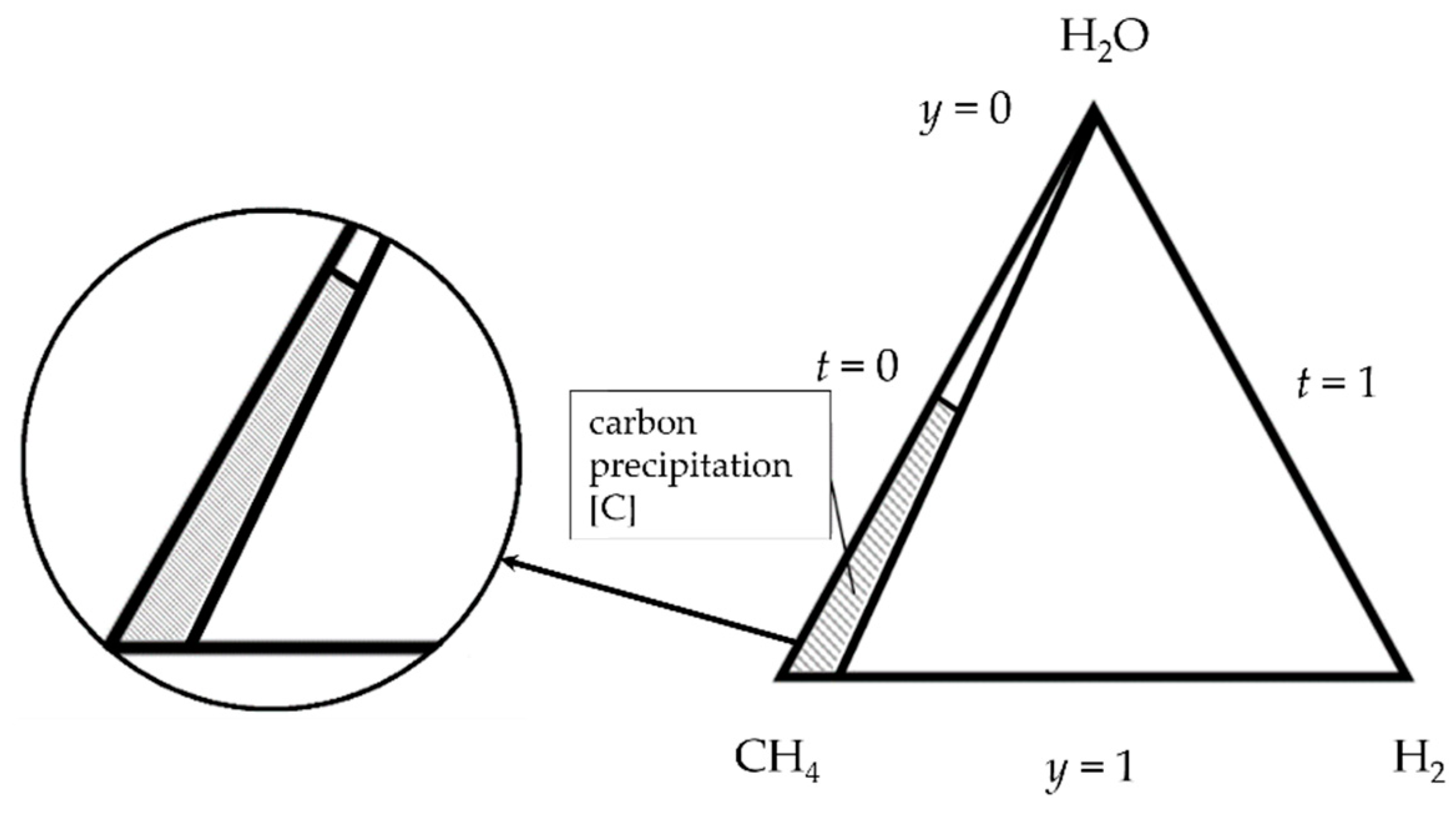
Graphical representation of the initial composition of the gaseous phase of the process, defined by variables (t, y) is shown in a Figure 1.
Values t are constant along a line with a set ratio of x H 2 0 / x C H 4 0 . These values vary from t = 0 (CH4–H2O steam reforming) to t = 1 representing equilibrium in the steam—hydrogen (H2O–H2) system. Parameter y = const defines lines that are parallel to the base of a triangle (y = 1) determining a ratio of the initial concentrations of hydrogen and methane. In the case of y = 0, we have a pure component which is steam.
Numerical calculations were carried out using mathematical computing environment MATLAB, on the basis of thermodynamic data [47]. Equilibrium constants were determined using the general relation:
G T 0 = R T ln K
where G T 0 represents a change in Gibbs free energy of the reaction, expressed by the relation:
G T 0 = i = 1 s k i μ A i 0 ,   i = 1 , ,   s
where: k i denote, if with a plus sign, stoichiometric coefficients of the products and, if with a minus sign, the substrates for the reaction set, whereas μ A i 0 denote standard chemical potentials of pure components, for the products and substrates, respectively.
The first stage of the analysis involved writing out parametric equations (Table 2), for the model reactions (Table 1), taking into account all components involved in the process (i = H2, CO, CO2, CH4, H2O). For a specific initial composition x i 0 expressed by variables (t, y) an equilibrium composition x i of the first model reaction was determined. Parameter τ was calculated by substituting appropriate parametric equations into equilibrium constant K. By way of example, for reaction (j = 1) the equilibrium constant is expressed by the relation:
K 1 = P C O P H 2 3 P H 2 O P C H 4 = x C O x H 2 3 x H 2 O x C H 4 P 2
K 1 = [ x C O 0 + ( 0.5 x C O 0 ) τ ] [ x H 2 0 + ( 1.5 x H 2 0 ) τ ] 3 [ x H 2 O 0 + ( 0.5 x H 2 O 0 ) τ ] [ x C H 4 0 + ( 0.5 x C H 4 0 ) τ ]
where: P—atmospheric pressure [1 atm].
By assuming, e.g., an initial composition of a gaseous mixture ( x H 2 O 0 = x C H 4 0 = 0.5 , x H 2 0 = 0 ) , we obtain an equation in respect of τ :
27 τ 4 16 K 1 τ 2 + 16 K 1 τ 4 K 1 = 0
having four roots ( τ 1 , τ 2 , τ 3 , τ 4 ), for which we calculate equilibrium compositions in accordance with the parametric equations for all components of the gaseous phase. Of the parameters τ searched for, only the one for which the following conditions are met makes physical sense:
{ 0 x i 1 i = 1 s x i = 1
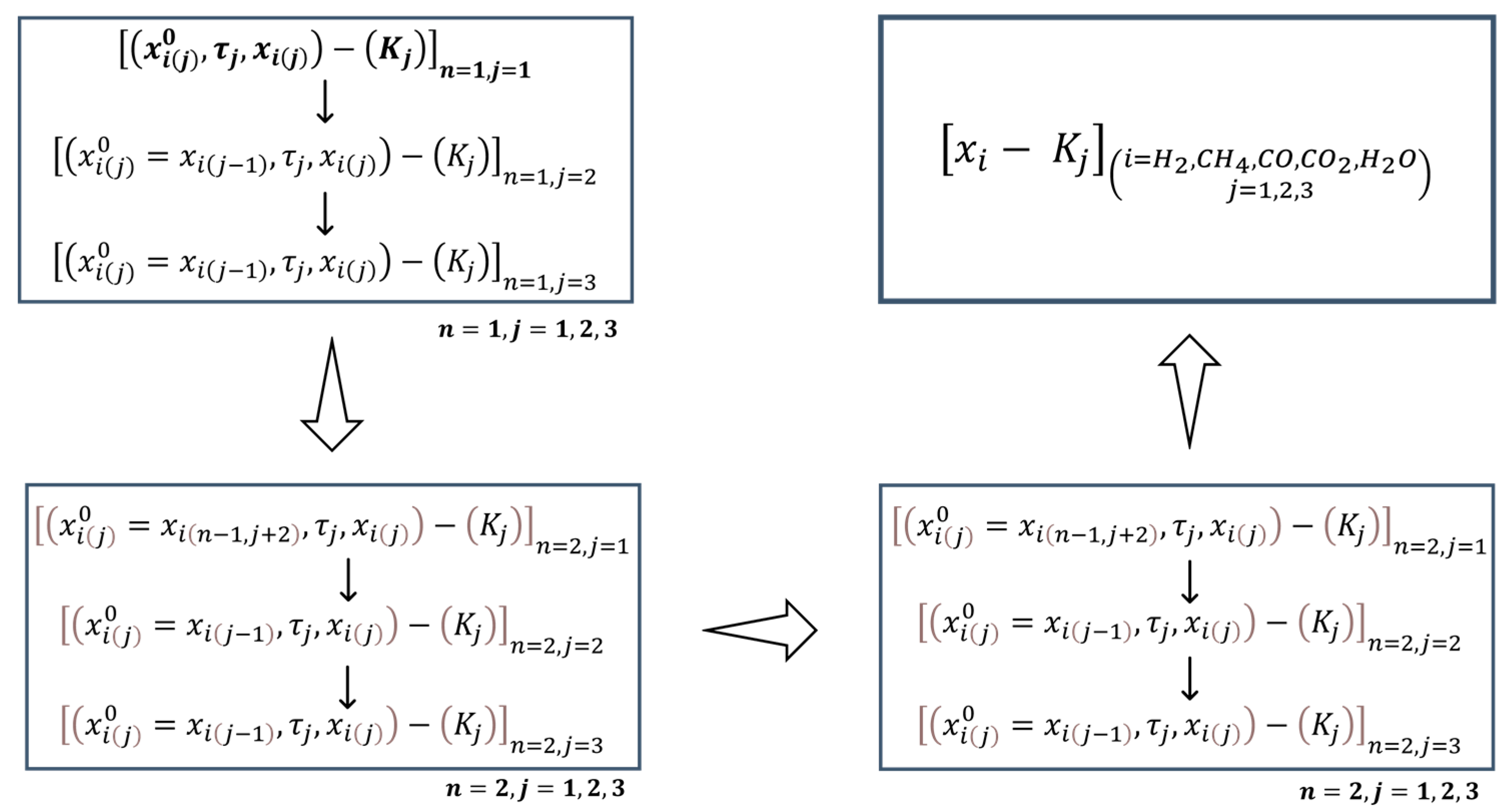
The equilibrium composition of the first model reaction served as an initial composition for the second reaction and the determined equilibrium composition of the second reaction became an initial composition for the subsequent reaction. Calculations were carried out in a loop (n = 1,…,s) until the final composition of the process satisfied the equilibrium constants for all the model reactions in accordance with the diagram below (Figure 2).
The interpretation of formation of the so-called carbon deposits in an ongoing steam reforming process in respect of CH4/H2 mixture was based on an equilibrium composition of the gaseous phase (H2, H2O, CH4, CO, CO2), in which thermal decomposition of methane and Bouduard reaction can occur (Table 3). Formation of the phase of pure carbon, whose activity is equal to one (a[C] = 1) as a result of thermal decomposition of methane and a Bouduard reaction is limited by the ratios of concentrations of the reforming process gaseous components ( α j ) in the on-going reactions (j = 5, 6) with equilibrium constants Kj.
An alternative method for determining the range of carbon precipitation in H2O–CH4–H2 ternary system could be the model approach to this problem as used in metal solution theory and, specifically, in describing the properties of multi-component thermodynamic systems. Such an approach limits costly experimental procedures or time-consuming numerical calculations. In the model interpretation, the thermodynamic properties in a three-component mixture are determined based on the knowledge of thermodynamic properties of binary boundary systems making up a multi-component system [48,49,50,51,52,53,54]. In such models, the so-called composition path is defined that determines the effect of individual two-component systems on the thermodynamic properties of complex systems. In this paper, the independent variable assumed (t, y) (Figure 1) [52,53,54] determine a component path conforming to the assumptions of Toop’s model [48]. According to these assumptions, using the symbol convention (k = H2O, l = CH4, m = H2), a carbon deposition boundary in a y [ C ] , k l m = f ( t , y ) H2O–CH4–H2 system can be expressed in the following form:
y [ C ] , k l m = ω k l y [ C ] , k l + ω k m y [ C ] , k m + ω l m y [ C ] , l m
for which coefficients ω k l , ω k m , ω l m have been defined as follows:
ω k l = x k x l x k ( l ) x l ( k ) ω k m = x k x m x k ( m ) x m ( k ) ω l m = x l x m x l ( m ) x m ( l )
where: x k , x l , x m —component concentrations expressed as mole fractions in ternary system k-l-m; x k ( l ) x l ( k ) , x k ( m ) x m ( k ) , x l ( m ) x m ( l ) —mole fractions of components in boundary two-component systems k-l, k-m, l-m.
Applying independent variables (t, y) we obtain function y [ C ] , k l m = f ( t , y ) for a boundary of the area of the homogeneous system of the gaseous phase in the reforming process, and a two-phase heterogeneous system with a constant phase, resulting from reaction (j = 5) (Table 3) involving carbon:
y [ C ] , k l m = ( 1 t ) y [ C ] , k l + t y [ C ] , k m + y 2 y [ C ] , l m
According to the composition path adopted, taking into account the shares of two-component systems H2O–CH4 [12,39,40,41,42,43], H2O–H2, CH4–H2 for temperature of T = 1000 K, the boundary conditions have been determined:
i n   s y s t e m   k l :   t = 0 ;   y [ C ] , k l = 0.45 i n   s y s t e m   k m :   t = 1 ;   y [ C ] , k m = 1 i n   s y s t e m   l m :   y = 1 ;   y [ C ] , k l = 0
allowing for determining trajectory y [ C ] , k l m = f ( t , y ) with the following equation:
y [ C ] , k l m = 0.55 t + 0.45

3. Analysis and Interpretation of Model Calculations

Numerical calculations for steam reforming of (CH4/H2) mixture were carried out in respect of the range of initial concentrations of components ( x H 2 O 0 , x C H 4 0 , x H 2 0 ) expressed through independent variables (t, y): t = 0–2 at y = 0.2–0.8, for standard state pressure P = 1 [atm.] and temperature from within the technological range of T = 1000 K. The first stage of the analysis involved determining equilibrium composition x i for all components involved in the process (i = H2, CO, CO2, CH4, H2O) in accordance with the formalism of parametric equations for model reactions. The calculations were carried out assuming set parameter t = const., for the following values t = 0, 0.02, 0.05, 0.1, 0.2 representing hydrogen content in methane, with a parameter y change step equal to ∆y = 0.005. The reference point in the analysis of the effect of hydrogen added to methane in the process under consideration is system (CH4–H2O) for t = 0, characterizing “classic” steam reforming of methane without initial hydrogen content in the process input mixture. Determining the conditions of carbon precipitation in the context of temperature and the process initial composition is an interesting aspect both from the cognitive and technological point of view. The carbon precipitation phenomenon, which slows down or even stops methane conversion, given its catalytic nature, limits the area of the initial process composition for which there is technological justification. With complete information on the equilibrium compositions of the reforming process of gaseous phase (CH4/H2)–H2O, in accordance with the thermodynamic condition (Table 3) a range was determined within which the so-called “carbon deposit” in the process is formed. For system CH4–H2O, which corresponds to parameter t = 0, initial ratio of steam and methane concentrations, expressed as S C = x H 2 O 0 / x C H 4 0 at temperature T = 1000 K is SC = 1.222 and above this level, no carbon precipitation occurs. The boundary of carbon precipitation as a result of ongoing methane conversion with steam, represented by parameter SC converges with the maximum value of equilibrium hydrogen concentration in the process. In the context of variables (t, y), that corresponds to the values of parameters t = 0, y = 0.45.
The results of numerical calculations of the effect of hydrogen in the initial composition on the carbon formation phenomenon are set forth in a Table 4. Adding hydrogen, in a mixture with methane (t = 0–0.2) to the system (CH4/H2)–H2O, limits the range within which carbon deposits form, which promotes conversion of methane by the possibility of decreasing initial steam pressure x H 2 O 0 . In order to describe relation y [ C ] = f ( t ) resulting from the numerical calculations a linear function shape was used, as was the case in Toop’s model. With the boundary condition set ( t 1 , y [ C ] 1 ) resulting from the thermodynamic properties of system H2O–H2, i.e., a system being free from carbon deposit formation, equation y [ C ] = f ( t ) can be condensed as:
y [ C ] = t b t + b
Taking into account data y [ C ] = f ( t ) of the numerical analysis, coefficient b = 0.4505 was determined, identifying linear dependency of the boundary of the area of the homogeneous system of the gaseous phase in the reforming process, and a two-phase system with a constant carbon phase, resulting from a methane decomposition reaction:
y [ C ] = 0.5495 t + 0.4505
A comparison of the model approach and an analytic description of the numerical data of carbon deposition range in system (CH4/H2)–H2O is illustrated in a Figure 3 and Figure 4 and set forth in a Table 4. The discrepancy between values y [ C ] = f ( t ) from the numerical calculations and values projected using Toop’s model: ∆y = 0.0005t − 0.0005 takes on a maximum value of ∆y = 0.0005 at boundary point (t = 0). Therefore, it is possible to simplify the determination of carbon deposition range in the process of steam reforming of gaseous mixture (CH4/H2) with an approach based on the familiarity with this phenomenon in binary two-component systems (H2O–CH4, H2O–H2, CH4–H2), according to Toop’s model assumptions.
At the next stage of the study, an analysis was carried out of the effect of hydrogen in the initial composition on the equilibrium concentrations in the process, with set parameter y = const, representing fixed concentration x H 2 O 0 . The analysis covered an area with concentrations that were technologically justified, i.e., free from carbon deposit formation. Therefore, included in the analysis were results for y = 0.2, 0.25, 0.3, 0.4, 0.5, it is worth noting that from the technological point of view, the most interesting processes were those with y = 0.2–0.25 of steam methane reforming (CH4–H2O, t = 0), corresponding to parameter SC = 4–3.
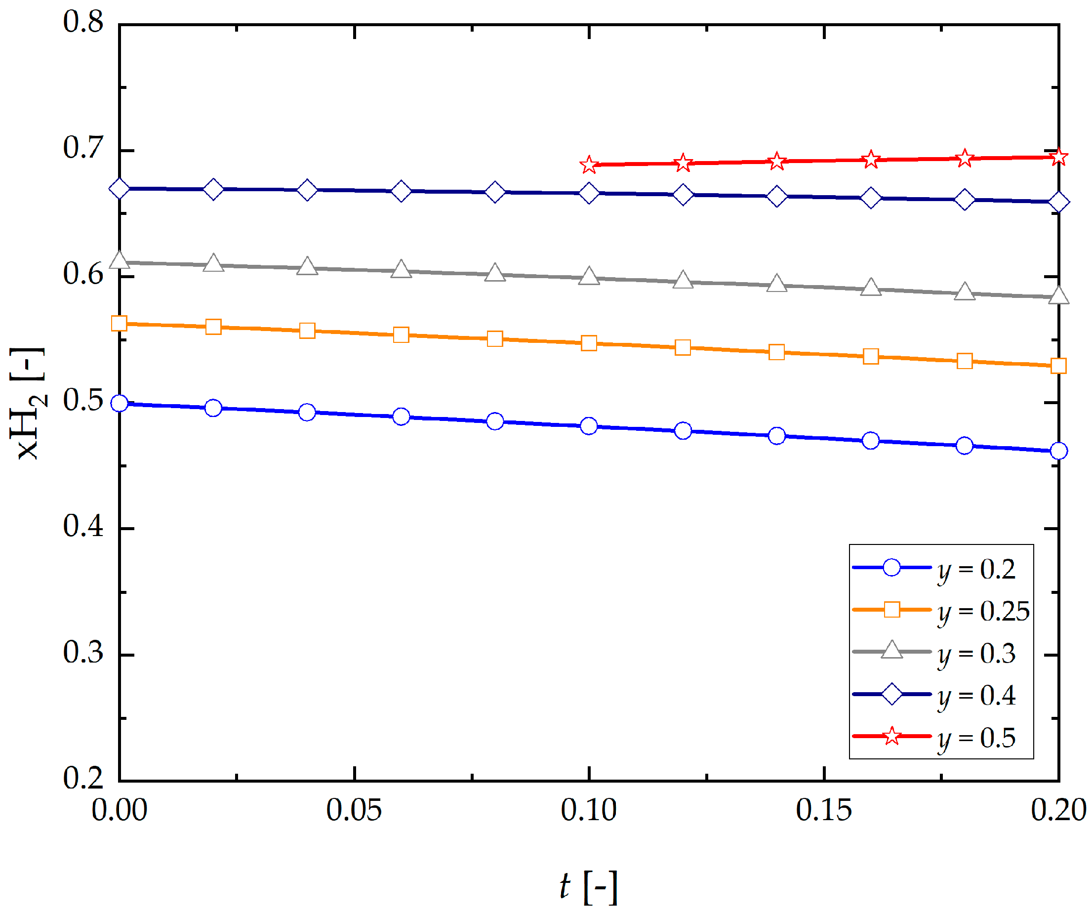
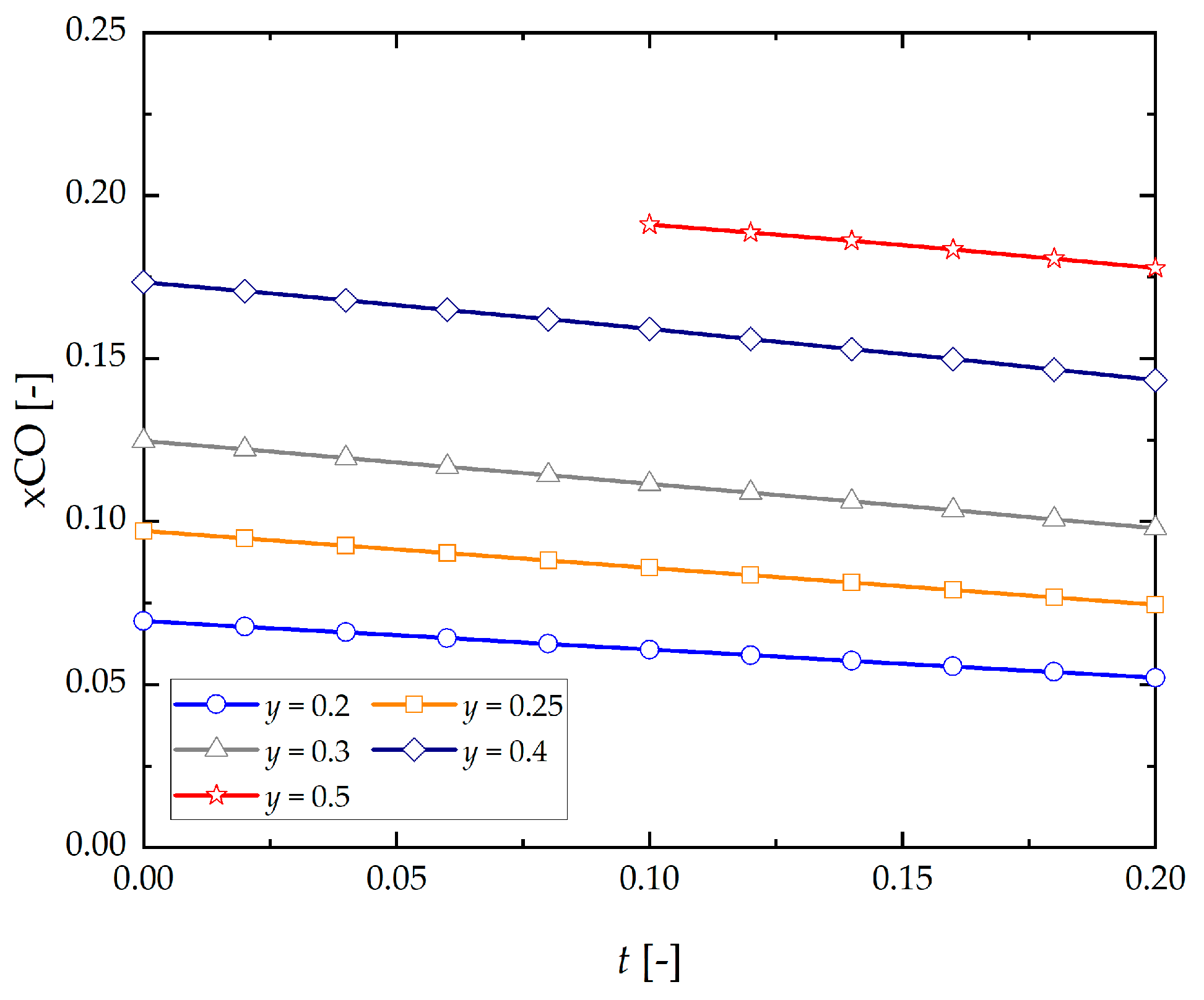
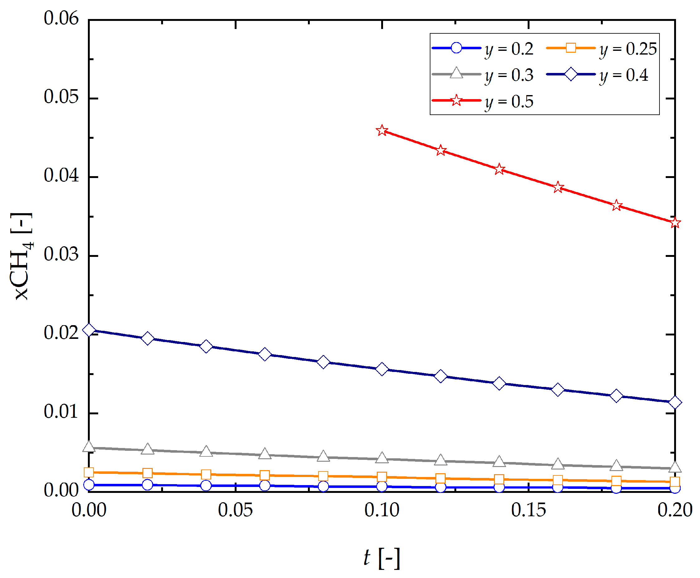
The generation of hydrogen in reforming gaseous phase (CH4/H2)–H2O slightly decreases as this component increases in the initial composition, ( x H 2 0 ) within the range y = 0.25–0.4, and an increase ( x H 2 O 0 ) is promotes this phenomenon (Figure 5). By way of example, for y = 0.25 hydrogen equilibrium concentration varies from x H 2 = 0.5629 with parameter t = 0 to x H 2 = 0.5290 with t = 0.2. By contrast, for y = 0.5 in an area free from carbon deposit within the range t = 0.1–0.2 an increase in hydrogen equilibrium concentration can be seen, from x H 2 = 0.6883 to x H 2 = 0.6945 . Similarly, in the case of CO, its equilibrium concentration in the process decreases as t increases, and steam intensifies this phenomenon (Figure 6). In addition, CH4 content in the products of ongoing reactions decreases with initial concentration of hydrogen ( x H 2 0 ) and steam ( x H 2 O 0 ) , (Figure 7).
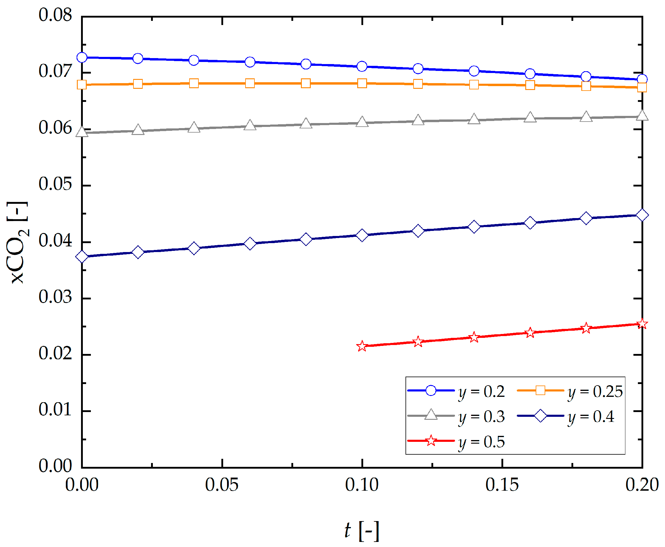
An increase in the initial concentration of hydrogen ( x H 2 0 ) in methane, and steam ( x H 2 O 0 ) in turn promotes generation of CO2 in process gases, it being understood that at high concentrations ( x H 2 O 0 ) , corresponding to y = 0.25, steam neutralizes effect ( x H 2 0 ) on rising tendency of CO2 formation in the process products (Figure 8). Concentrations of H2O in the gaseous phase in thermodynamic equilibrium of the process increase in proportion to the initial composition of hydrogen and steam of the gaseous mixture being supplied into the system (Figure 9).

4. Summary

The above thermodynamic analysis of the effect of hydrogen found in methane on the process of steam reforming of gaseous phase (CH4/H2) yields a few significant conclusions:
  • Adding hydrogen, in a mixture with methane (t = 0–0.2) to system (CH4/H2)–H2O limits the range within which carbon deposits form, which promotes conversion of methane by the possibility of decreasing initial steam pressure x H 2 O 0 .
  • Therefore, it is possible to simplify the determination of carbon deposition range in the process of steam reforming of gaseous mixture (CH4/H2) with an approach based on the familiarity with this phenomenon in binary two-component systems (H2O–CH4, H2O–H2, CH4–H2), according to Toop’s model assumptions.
  • As steam content x H 2 O 0 added to the system in an area free from carbon deposition for a range of initial concentrations (t = 0–0.2; y = 0.2–y[C]) increases, there occurs a monotonic decrease in equilibrium concentrations of H2, CO, CH4 and an increase of CO2, H2O in the process being analyzed.
  • The generation of hydrogen in reforming gaseous phase (CH4/H2)–H2O slightly decreases as this component increases in the initial composition ( x H 2 0 ) , within the range y = 0.25–0.4, and an increase ( x H 2 O 0 ) promotes this phenomenon.
  • Equilibrium concentration of CO decreases as t increases, and steam intensifies this phenomenon.
  • An increase in initial concentration of hydrogen ( x H 2 0 ) in methane, and steam ( x H 2 O 0 ) in turn promotes generation of CO2 in process gases, it being understood that at high concentrations ( x H 2 O 0 ) corresponding to y = 0.25 steam neutralizes effect ( x H 2 0 ) on rising tendency of CO2 in the process products.
  • Concentrations of H2O in the gaseous phase in thermodynamic equilibrium of the process increase in proportion to the initial composition of hydrogen and steam of the gaseous mixture being supplied into the system.
  • CH4 content in the products decreases with initial concentration of hydrogen ( x H 2 0 ) and steam ( x H 2 O 0 ).
The results obtained can serve as a model basis for describing the properties of steam reforming of methane and hydrogen mixture (CH4/H2)–H2O. Such an approach in the thermodynamic analysis creates opportunities for verification, comparisons, and implementation of research works on catalytic properties of materials limiting the efficiency and economics of the process and ecological aspects related to the emission of greenhouse gases in this technological area. Furthermore, in new research areas of photocatalytic reforming processes, in which the type and properties of the catalyst play an important role, the presented thermodynamic analysis can be used to optimize the trajectories of temporal changes in gas-phase concentrations resulting from the progress of the reaction in the system.

Funding

The author acknowledges the support of the Initiative for Excellence—a Research University Project at AGH University of Science and Technology and the Polish Ministry of Science and Higher Education (AGH Grant No.16.16.210.476).

Institutional Review Board Statement

Not applicable.

Informed Consent Statement

Not applicable.

Data Availability Statement

Data available on reasonable request.

Conflicts of Interest

The author declares no conflict of interest. The founding sponsors had no role in the design of the study; in the collection, analyses, or interpretation of data; in the writing of the manuscript, and in the decision to publish the results.

References

  1. Gahleitner, G. Hydrogen from renewable electricity: An international review of power-to-gas pilot plants for stationary applications. Int. J. Hydrogen Energy 2013, 3, 2039–2061. [Google Scholar] [CrossRef]
  2. Grond, L.; Schulze, P.; Holstein, J. Systems Analyses Power to Gas: A Technology Review; DNV KEMA Energy & Sustainability; KEMA: Groningen, The Netherlands, 2013. [Google Scholar]
  3. Altfeld, K.; Pinchbeck, D. Admissible Hydrogen Concentrations in Natural Gas Systems; Gas For Energy; DIV Deutscher Industrieverlag: Munchen, Germany, 2013; Available online: https://www.gerg.eu/wp-content/uploads/2019/10/HIPS_Final-Report.pdf (accessed on 11 October 2021).
  4. Müller-Syring, G.; Henel, M.; Köppel, W.; Mlaker, H.; Sterner, M.; Höcher, T. Entwicklung von Modularen Konzepten zur Erzeugung, Speicherung und Einspeisung von Wasserstoff und Methan ins Erdgasnetz; DVGW-Projekt G1-07-10; DNV KEMA: Arnhem, The Netherlands, 2013; Available online: https://www.dvgw.de/medien/dvgw/forschung/berichte/g1_07_10.pdf (accessed on 11 October 2021).
  5. Melaina, M.W.; Antonia, O.; Penev, M. Blending Hydrogen into Natural Gas Pipeline Networks: A Review of Key Issues Technical; Report NREL/TP-5600-51995; National Renewable Energy Laboratory: Denver, CO, USA, 2013. Available online: https://www.nrel.gov/docs/fy13osti/51995.pdf (accessed on 11 October 2021).
  6. van der Zwaan, B.; Schoots, K.; Rivera-Tinoco, R.; Verbong, G. The cost of pipelining climate change mitigation: An overview of the economics of CH4, CO2 and H2 transportation. Appl. Energy 2011, 88, 3821–3831. [Google Scholar] [CrossRef] [Green Version]
  7. Dodds, P.E.; Demoullin, S. Conversion of the UK gas system to transport hydrogen. Int. J. Hydrogen Energy 2013, 38, 7189–7200. [Google Scholar] [CrossRef] [Green Version]
  8. Durbin, D.J.; Malardier-Jugroot, C. Review of hydrogen storage techniques for on board vehicle applications. Int. J. Hydrogen Energy 2013, 38, 14595–14617. [Google Scholar] [CrossRef]
  9. Messaoudani, Z.L.; Rigas, F.; Hamid, B.D.M.; Hassan, C.R.C. Hazards, safety and knowledge gaps on hydrogen transmission via natural gas grid: A critical review. Int. J. Hydrogen Energy 2016, 41, 17511–17525. [Google Scholar] [CrossRef]
  10. Gondal, I.A. Hydrogen integration in power-to-gas networks. Int. J. Hydrogen Energy 2018, 44, 1803–1815. [Google Scholar] [CrossRef]
  11. Meng, B.; Gu, C.; Zhang, L.; Zhou, C.; Li, X.; Zhao, Y.; Zheng, J.; Chen, X.; Han, Y. Hydrogen effects on X80 pipeline steel in high-pressure natural gas/hydrogen mixtures. Int. J. Hydrogen Energy 2016, 42, 7404–7412. [Google Scholar] [CrossRef]
  12. Kaczmarczyk, R.; Gurgul, S. A thermodynamic analysis of heavy hydrocarbons reforming for solid oxide fuel cell application as a part of hybrid energy systems. Energies 2021, 14, 337. [Google Scholar] [CrossRef]
  13. Chalusiak, M.; Wrobel, M.; Mozdzierz, M.; Berent, K.; Szmyd, J.S.; Kimijima, S.; Brus, G. A numerical analysis of unsteady transport phenomena in a Direct Internal Reforming Solid Oxide Fuel Cell. Int. J. Heat Mass Transf. 2019, 131, 1032–1051. [Google Scholar] [CrossRef]
  14. Tomiczek, M.; Kaczmarczyk, R.; Mozdzierz, M.; Brus, G. A numerical analysis of heat and mass transfer during the steam reforming process of ethane. Heat Mass Transf. 2017, 54, 2305–2314. [Google Scholar] [CrossRef]
  15. Liu, C.; Ye, J.; Jiang, J.; Pan, Y. Progresses in the preparation of coke resistant Ni-based catalyst for steam and CO2 reforming of methane. ChemCatChem 2011, 3, 529–541. [Google Scholar] [CrossRef]
  16. Tang, S.B.; Qiu, F.L.; Lu, S.J. Effect of supports on the carbon deposition of nickel catalysts for methane reforming with CO2. Catal. Today 1995, 24, 253–255. [Google Scholar] [CrossRef]
  17. Tomishige, K.; Himeno, Y.; Matsuo, Y.; Yoshinaga, Y.; Fujimoto, K. Catalytic performance and carbon deposition behavior of a NiO-MgO solid solution in methane reforming with carbon dioxide under pressurized conditions. Ind. Eng. Chem. Res. 2000, 39, 1891–1897. [Google Scholar] [CrossRef]
  18. Das, S.; Ashok, J.; Bian, Z.; Dewangan, N.; Wai, M.H.; Du, Y.; Borgna, A.; Hidajat, K.; Kawi, S. Silica—Ceria sandwiched Ni core—Shell catalyst for low temperature dry reforming of biogas: Coke resistance and mechanistic insights. Appl. Catal. B Environ. 2018, 230, 220–236. [Google Scholar] [CrossRef]
  19. Wang, Y.; Yao, L.; Wang, Y.; Wang, S.; Zhao, Q.; Mao, D.; Hu, C. Low-temperature catalytic CO2 Dry reforming of methane on Ni-Si/ZrO2 catalyst. ACS Catal. 2018, 8, 6495–6506. [Google Scholar] [CrossRef]
  20. Shen, J.; Reule, A.A.C.; Semagina, N. Ni/MgAl2O4 catalyst for low-temperature oxidative dry methane reforming with CO2. Int. J. Hydrogen Energy 2019, 44, 4616–4629. [Google Scholar] [CrossRef]
  21. Agrafiotis, C.; Von Storch, H.; Roeb, M.; Sattler, C. Solar thermal reforming of methane feedstocks for hydrogen and syngas production—A review. Renew. Sustain. Energy Rev. 2014, 29, 656–682. [Google Scholar] [CrossRef]
  22. Gokon, N.; Yamawaki, Y.; Nakazawa, D.; Kodama, T. Ni/MgO-Al2O3 and Ni-Mg-O catalyzed SiC foam absorbers for high temperature solar reforming of methane. Int. J. Hydrogen Energy 2010, 35, 7441–7453. [Google Scholar] [CrossRef]
  23. Tan, S.S.; Zou, L.; Hu, E. Photocatalytic reduction of carbon dioxide into gaseous hydrocarbon using TiO2 pellets. Catal. Today 2006, 115, 269–273. [Google Scholar] [CrossRef]
  24. Ohno, T.; Sarukawa, K.; Tokieda, K.; Matsumura, M. Morphology of a TiO2 photocatalyst (Degussa, P-25) consisting of anatase and rutile crystalline phases. J. Catal. 2001, 203, 82–86. [Google Scholar] [CrossRef]
  25. Park, H.; Park, Y.; Kim, W.; Choi, W. Surface modification of TiO2 photocatalyst for environmental applications. J. Photochem. Photobiol. C Photochem. Rev. 2013, 15, 1–20. [Google Scholar] [CrossRef]
  26. Yoshida, H.; Hirao, K.; Nishimoto, J.; Shimura, K.; Kato, S.; Itoh, H.; Hattori, T. Hydrogen production from methane and water on platinum loaded titanium oxide photocatalysts. J. Phys. Chem. C 2008, 112, 5542–5551. [Google Scholar] [CrossRef]
  27. Shimura, K.; Kato, S.; Yoshida, T.; Itoh, H.; Hattori, T.; Yoshida, H. Photocatalytic steam reforming of methane over sodium tantalate. J. Phys. Chem. C 2010, 114, 3493–3503. [Google Scholar] [CrossRef]
  28. Balázs, L.; Baán, K.; Varga, E.; Oszkó, A.; Erdőhelyi, A.; Kónya, Z.; Kiss, J. Photo-induced reactions in the CO2-methane system on titanate nanotubes modified with Au and Rh nanoparticles. Appl. Catal. B Environ. 2016, 199, 473–484. [Google Scholar]
  29. Cho, Y.; Yamaguchi, A.; Miyauchi, M. Photocatalytic methane reforming: Recent advances. Catalysts 2021, 11, 18. [Google Scholar] [CrossRef]
  30. Susmozas, A.; Iribarren, D.; Dufour, J. Life-cycle performance of indirect biomass gasification as a green alternative to steam methane reforming for hydrogen production. Int. J. Hydrogen Energy 2013, 38, 9961–9972. [Google Scholar] [CrossRef]
  31. Di Marcoberardino, G.; Vitali, D.; Spinelli, F.; Binotti, M.; Manzolini, G. Green hydrogen production from raw biogas: A Techno-economic investigation of conventional processes using pressure swing adsorption unit. Processes 2018, 6, 19. [Google Scholar] [CrossRef] [Green Version]
  32. Minutillo, M.; Perna, A.; Sorce, A. Green hydrogen production plants via biogas steam and autothermal reforming processes energy and exergy analyses. Appl. Energy 2020, 277, 115452. [Google Scholar] [CrossRef]
  33. Tuna, C.E.; Silveira, J.L.; da Silva, M.E.; Boloy, R.M.; Braga, L.B.; Pérez, N.P. Biogas steam reformer for hydrogen production: Evaluation of the reformer prototype and catalysts. Int. J. Hydrogen Energy 2018, 43, 2108–2120. [Google Scholar] [CrossRef] [Green Version]
  34. Prodromidis, G.N.; Coutelieris, F.A. The effect of biogas origin on the electricity production by solid oxide fuel cells. Appl. Sci. 2021, 11, 3112. [Google Scholar] [CrossRef]
  35. Pajak, M.; Brus, G.; Szmyd, J.S. Catalyst distribution optimization scheme for effective green hydrogen production from biogas reforming. Energies 2021, 14, 5558. [Google Scholar] [CrossRef]
  36. Ptak, W.; Sukiennik, M. Changes in the composition of the gaseous phase of a system resulting from the process of a chemical reaction. Bull. Acad. Pol. Sci. 1969, 17, 21–25. [Google Scholar]
  37. Ptak, W.; Sukiennik, M. The kinetics characteristic of complex systems. Arch. Metall. 1973, 18, 275–289. [Google Scholar]
  38. Ptak, W.; Sukiennik, M.; Olesinski, R.; Kaczmarczyk, R. Deformation of a properties resulting from a chemical reaction stoichiometry. Arch. Metall. 1987, 32, 355–362. [Google Scholar]
  39. Kaczmarczyk, R.; Gurgul, S. Model approach of carbon deposition phenomenon in mixed H2O/CO2 methane reforming process. Arch. Metall. Mater. 2014, 59, 1379–1383. [Google Scholar] [CrossRef] [Green Version]
  40. Kaczmarczyk, R.; Gurgul, S. Model approach of carbon deposition phenomenon in steam and dry methane reforming process. Arch. Metall. Mater. 2014, 59, 145–148. [Google Scholar] [CrossRef] [Green Version]
  41. Brus, G. Experimental and numerical studies on chemically reacting gas flow in the porous structure of a solid oxide fuel cells internal fuel reformer. Int. J. Hydrogen Energy 2012, 37, 17225–17234. [Google Scholar] [CrossRef]
  42. Sciazko, A.; Komatsu, Y.; Brus, G.; Kimijima, S. A novel approach to improve the mathematical modelling of the internal reforming process for solid oxide fuel cells using the orthogonal least squares method. Int. J. Hydrogen Energy 2014, 39, 16372–16389. [Google Scholar] [CrossRef]
  43. Sciazko, A.; Komatsu, Y.; Brus, G.; Kimijima, S.; Szmyd, J.S. A novel approach to the experimental study on methane/steam reforming kinetics using the Orthogonal Least Squares method. J. Power Sources 2014, 262, 245–254. [Google Scholar] [CrossRef]
  44. Pajak, M.; Mozdzierz, M.; Chalusiak, M.; Kimijima, S.; Szmyd, J.S.; Brus, G. A numerical analysis of heat and mass transfer processes in a macro-patterned methane/steam reforming reactor. Int. J. Hydrogen Energy 2018, 43, 20474–20487. [Google Scholar] [CrossRef]
  45. Delgado, K.H.; Maier, L.; Tischer, S.; Zellner, A.; Stotz, H. Surface reaction kinetics of steam-and CO2-reforming as well as oxidation of methane over nickel-based catalysts. Catalysts 2015, 5, 871–904. [Google Scholar] [CrossRef] [Green Version]
  46. York, A.P.E.; Xiao, T.C.; Green, M.L.H.; Claridge, J.B. Methane oxyforming for synthesis gas production. Catal. Rev. 2007, 49, 511–560. [Google Scholar] [CrossRef]
  47. Knacke, O.; Kubaschewski, O.; Hesselmann, K. Thermochemical Properties of Inorganic Substaces; Springer: Berlin, Germany, 1991. [Google Scholar]
  48. Toop, G.W. Predicting ternary activities using binary data. Trans. Metall. Soc. AIME 1965, 233, 850–855. [Google Scholar]
  49. Kohler, F. Estimation of the thermodynamic data for a ternary system from the corresponding binary systems. Monatsh. Chem. 1960, 91, 738–740. [Google Scholar] [CrossRef]
  50. Muggianu, Y.M.; Gambino, M.; Bros, J.P. Enthalpies de formation des alliages liquides bismuth-étain-gallium à 723 K. Choix d’une représentation analytique des grandeurs d’excès intégrales et partielles de mélange. J. Chim. Phys. 1975, 72, 83–88. [Google Scholar] [CrossRef]
  51. Hillert, M. Empirical methods of predicting and representing thermodynamic properties of ternary solution phases. Calphad 1980, 4, 1–12. [Google Scholar] [CrossRef]
  52. Pelton, A.D.; Blander, M. Thermodynamic analysis of ordered liquid solutions by a modified quasichemical approach—Application to silicate slags. Metall. Mater. Trans. B 1986, 17, 805–815. [Google Scholar] [CrossRef]
  53. Chartrand, P.; Pelton, A.D. On the choice of “geometric” thermodynamic models. J. Phase Equilibria 2000, 21, 141–147. [Google Scholar] [CrossRef]
  54. Pelton, A.D. A general “geometric” thermodynamic model for multicomponent solutions. Calphad 2001, 25, 319–328. [Google Scholar] [CrossRef]
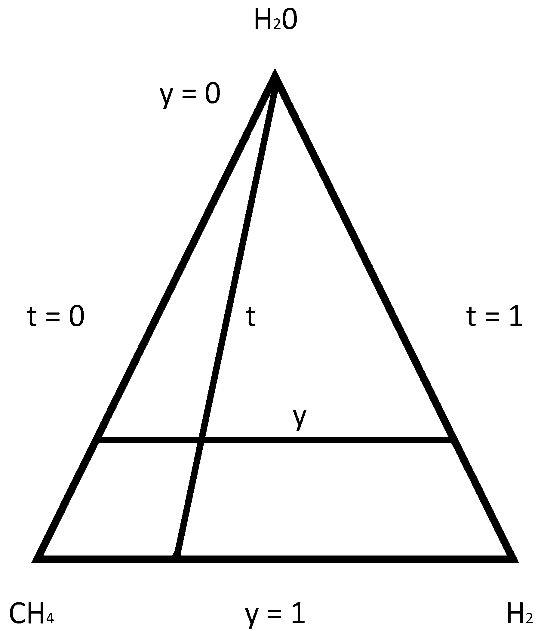
Figure 1. Initial composition ( x H 2 O 0 , x C H 4 0 , x H 2 0 ) of gaseous mixture (CH4/H2)–H2O as a function of t and y.
Energies 14 06564 g001
Figure 2. Numerical calculations of equilibrium composition x i (i = H2, CO, CO2, CH4, H2O) for the process of steam reforming of a gaseous mixture (CH4/H2), using parametric equations.
Energies 14 06564 g002
Figure 3. Range of carbon precipitation [C] = f(t, y) for T = 1000 K in system (CH4/H2)–H2O according to the numerical calculations and Toop’s model.
Energies 14 06564 g003
Figure 4. Range of carbon precipitation [C] = f(t, y) for T = 1000 K in system (CH4/H2)–H2O.
Energies 14 06564 g004
Figure 5. Change in equilibrium composition x H 2 = f ( t , y ) with y = const, of the reforming process of gaseous phase (CH4/H2)–H2O.
Energies 14 06564 g005
Figure 6. Change in equilibrium composition x C O = f ( t , y ) with y = const, of the reforming process of gaseous phase (CH4/H2)–H2O.
Energies 14 06564 g006
Figure 7. Change in equilibrium composition x C H 4 = f ( t , y ) with y = const, of the reforming process of gaseous phase (CH4/H2)–H2O.
Energies 14 06564 g007
Figure 8. Change in equilibrium composition x C O 2 = f ( t , y ) with y = const, of the reforming process of gaseous phase (CH4/H2)–H2O.
Energies 14 06564 g008
Figure 9. Change in equilibrium composition x H 2 O = f ( t , y ) with y=const, of the reforming process of gaseous phase (CH4/H2)–H2O.
Energies 14 06564 g009
Table 1. Model reactions (j = 1, 2, 3) in steam reforming of a CH4/H2 system.
jReaction i = 1 s k i
1CH4(g) + H2O(g) ↔ CO(g) + 3H2(g)2
2CO(g) + H2O(g)↔ CO2(g) + H2(g)0
3CH4(g) + CO2(g) ↔ 2CO(g) + 2H2(g)2
Table 2. Parametric equations for the equilibrium compositions of components (i = 1, 2, 3, 4, 5) of the gaseous phase, for model reactions (j = 1, 2, 3) of steam reforming of a CH4/H2 system.
i = 1 s k i 0               x i = x i 0 + ( x ¯ i x i 0 ) τ ,     x ¯ i = k i i = 1 s k i ,     i = 1 ,   2 ,   3 , , s
i = 1 s k i = 0               x i = x i 0 + τ k i i = 1 s ( k i ) 2 ,     i = 1 ,   2 ,   3 , , s
i = 1,…,5j = 1j = 2j = 3
H2 x H 2 o + ( 1.5 x H 2 0 ) τ x H 2 o + 0.5 τ x H 2 o + ( 1 x H 2 0 ) τ
CO x C O o + ( 0.5 x C O 0 ) τ x C O o 0.5 τ x C O o + ( 1 x C O 0 ) τ
H2O x H 2 O o + ( 0.5 x H 2 O 0 ) τ x H 2 O o 0.5 τ x H 2 O o x H 2 O 0 τ
CO2 x C O 2 o x C O 2 0 τ x C O 2 o + 0.5 τ x C O 2 o + ( 0.5 x C O 2 0 ) τ
CH4 x C H 4 o + ( 0.5 x C H 4 0 ) τ x C H 4 o x C H 4 o + ( 0.5 x C H 4 0 ) τ
Table 3. A condition for carbon precipitation in the gaseous phase (H2, H2O, CH4, CO, CO2).
jReaction K j α j a [ C ] = 1
5 CH 4 [ C ] + 2 H 2 exp ( G T ( j ) 0 R T ) = x H 2 2 · a [ C ] x C H 4 α 5 = x H 2 2 x C H 4 [ C ] = { α 5 K 5 α 6 K 6
6 [ C ] + CO 2 2 CO exp ( G T ( j ) 0 R T ) = x C O 2 x C O 2 · a [ C ] α 6 = x C O 2 x C O 2
G T 0 [J/mol], R = 8.314 [J/mol K]
Table 4. Rangef carbon precipitation [C] = f(t, y) for T = 1000 K in system (CH4/H2)–H2O according to the numerical calculations and Toop’s model.
ty[C] x H 2 O 0 x C H 4 0 x H 2 0 S C = x H 2 O 0 / x C H 4 0 y[C]
(22)
y[C]
Toop (20)
0.000.4500.5500.45000.00001.2220.45050.4500
0.020.4650.5350.45570.00931.1740.46150.4610
0.050.4800.5200.45600.02401.1400.47800.4775
0.100.5050.4950.45450.05051.0890.50540.5050
0.200.5550.4450.44400.11101.0020.56040.5600
Publisher’s Note: MDPI stays neutral with regard to jurisdictional claims in published maps and institutional affiliations.