Article

Evaluation of Surfactant Mixture for Supercritical Carbon Dioxide Foamed Acid in Carbonate Matrix Acidizing

1
Department of Petroleum Resources Technology, University of Science and Technology (UST), Daejeon 34113, Korea
2
Petroleum and Marine Research Division, Korea Institute of Geoscience and Mineral Resources, Daejeon 34132, Korea
*
Author to whom correspondence should be addressed.
Energies 2021, 14(20), 6567; https://doi.org/10.3390/en14206567
Submission received: 31 August 2021 / Revised: 24 September 2021 / Accepted: 8 October 2021 / Published: 12 October 2021
(This article belongs to the Topic Enhanced Oil Recovery Technologies)

Abstract

:
The effectiveness of matrix acidizing using CO2 foamed acid is dependent on the duration of foam stability. This paper presents a supercritical CO2 foamed acid with a surfactant mixture to improve the foam stability in carbonate matrix acidizing. The experimental apparatus was developed to conduct foam-stability and wormhole-propagation tests under high-pressure and high-temperature (HPHT) conditions. The foam decay times of five types of surfactants were measured under atmospheric conditions. Trimax (blend of cocamidopropyl betaine, disodium cocoamphodiacetate, and amine oxide) and Aromox C/12W (coco bis-(2-hydroxyethyl) amine oxide) had a high foam decay time. The surfactant mixture was prepared using these two surfactants. The foam stability tests of the surfactant mixture were performed according to the HCl concentration, surfactant mixing ratio, and injection rate of HCl under HPHT conditions. As a result, the foam stability could be improved by adding an HCl concentration of 20% to the surfactant mixture. Wormhole-propagation tests were performed using Indiana and Indonesian limestones. Because of the supercritical CO2 foamed acid injection, dominant wormholes were formed in all the core samples; thus, the absolute permeabilities significantly increased. The results of the scanning electron microscopy/energy-dispersive X-ray spectroscopy and thin-section analyses revealed that the number of large pores with pore sizes of ≥0.5 mm increased by the injection of CO2 foamed acid. Therefore, the supercritical CO2 foamed acid with the surfactant mixture exhibited a high efficiency of matrix acidizing in carbonate reservoirs.

1. Introduction

Carbonate matrix acidizing is a reservoir stimulation technique that improves oil recovery by injecting reactive acid into the carbonate reservoirs [1]. During matrix acidizing, the effective drainage radius of a well can be extended by dissolving reservoir rock and creating high conductivity channels called wormholes [2]. Most acid treatments in carbonate reservoirs are performed using HCl. HCl is used in combination with corrosion inhibitors and other chemical additives to protect injection equipment from corrosion and control acid reactions [3]. Moreover, HCl is a strong acid that is mass-transfer limited in its reaction with limestone at temperatures above 32 °F [4]. However, HCl may not exhibit a favorable stimulation effect with respect to heterogeneous reservoirs, multiple zones, or thick formations [5,6]. For reservoirs with high heterogeneity, the low permeability zone cannot be effectively treated by conventional acidizing with HCl because acid enters the layer with high permeability zone or the less damaged zone first according to the principle of least resistance selection [7]. The water cut can be increased as the acid flows into the water-saturated high permeability zone in heterogeneous reservoirs. Thus, the conventional acidizing in the reservoir with high permeability contrast has low efficiency in the fluid control. Furthermore, it is necessary to pay attention to the application of conventional acidizing in the high temperature reservoir due to the fast reaction rate between the acid and reservoir rock.
The mechanical diverters and chemical diverters are used to divert the acid to the low permeability zone or untreated zone [8]. The mechanical diverters typically include ball sealers, coiled tubing, and inflow control devices. These approaches have a good performance for acid diversion, but require high operational cost. Furthermore, the use of mechanical diverters in high temperature reservoirs is limited due to corrosion issues in the equipment. On the other hand, the chemical diverters, such as emulsified acids, foams and gelled acid-based polymers or surfactants, can be used efficiently under high-pressure and high-temperature (HPHT) conditions [8,9,10,11,12,13]. The emulsified acids can reduce fluid loss and increase acid penetration in high temperature reservoirs. The gelled acid is a method to increase the sweep efficiency by increasing the fluid viscosity. The foamed acid can divert acid into a low-permeability zone by temporarily blocking the high permeability zone [14,15]. The foamed acid is more effective for stimulation of low permeability reservoirs than other chemical diverts [16]. The foamed acid is also a retardant acid, which can reduce the acid–rock reaction rate and achieve deep acidizing [6]. The foamed acid treatment, with its advantages of diversion, slow speed, low water sensitivity, and retardant of acid-rock reaction can solve the limitations of conventional acidizing, so it has attracted much attention in the petroleum industry [7,17,18,19,20,21]. The gases commonly used to make foamed acid include carbon dioxide (CO2) and nitrogen (N2). Under the typical reservoir conditions, CO2 reaches supercritical condition while N2 remains in subcritical condition. The CO2 foam has several characteristics compared to N2 foam: lower interfacial tension between supercritical CO2 and lamella, solubility effects of CO2, low pH with CO2 foam, greater viscosity of supercritical CO2 [22,23]. In this study, the supercritical CO2 foamed acid was selected for carbonate matrix acidizing.
In matrix acidizing using foamed acid, the foam stability must be maintained over a long period. Foam stability is dependent on many factors, such as the surfactant type, concentration, thermal stability, and salinity tolerance of the surfactant or foaming agent [24]. Foam stability can be improved by using various surfactant mixtures. Many studies on the effect of surfactant mixture on foam stability have been conducted in the field of enhanced oil recovery [25,26,27,28,29,30,31,32,33]. Andrianov et al. [25] found that the mixture of fluorocarbon surfactant and alpha olefin sulfonate improved the foam stability. Almobarky et al. [28] investigated the mixing of alcohol alkoxy sulfate and internal olefin sulfonate for an enhanced oil recovery (EOR) process. The surfactant mixtures exhibited higher performance than the individual surfactants in that the foam viscosity increased and the mobility decreased [28]. Alli et al. [29] analyzed the effect of anionic and nonionic co-surfactants on the solubility of polyoxy based-surfactant (POS). They found that the addition of co-surfactants improved the solubility of POS at 60 °C. Curbelo et al. [30] and Kesarwani et al. [31] studied mixtures of ionic and nonionic surfactants to reduce the fluid loss due to surfactant adsorption during the EOR process. Kumari et al. [32] also prepared a surfactant mixture for EOR by using cationic and anionic surfactants. Anionic-cationic mixed surfactant improved foaming ability, and oil recovery was increased by using the surfactant mixture. Osei-Bonsu et al. [33] performed a foam stability test using CocoSDS prepared by mixing cocamidopropyl betaine (Cocobetaine) and sodium dodecyl sulphate (SDS) in a 1:1 ratio. As a result of experiments, the foam stability was increased because the lamellae and the Plateau borders generated by CocoSDS were thicker than those generated by a single surfactant.
Surfactant mixtures have been used to improve the performance of fracturing fluids in shale reservoirs. He and Xu [34] conducted an experimental study on the combination of binary mixtures using anionic, cationic, and nonionic surfactant to utilize surfactant mixture for liquid-rich shale reservoirs. As a result of the experiments, the anionic-cationic mixtures were thermodynamically stable, and strong synergism was observed in the mixed micelles and monolayers at the interface. As shown in the literature, surfactant mixture can improve the stability and performance of foam fluids, so it can be reasonably expected that surfactant mixture can have a positive effect in foamed acid treatment. However, most studies conducted on surfactant mixtures were mainly focused on EOR and unconventional reservoirs.
Few experimental studies were conducted to analyze the performance of the CO2 foamed acid under HPHT conditions [21]. Yan et al. [21] conducted supercritical CO2-foaming and core-flooding tests at a pressure of 1450 psi and a temperature of 60 °C to verify the performance of foamed acid diversion. As a result of experiments, the characteristics of wormhole propagation and diversion of CO2 foamed acid were identified by analyzing the pressure drop profile according to the injected fluid volume in the carbonate core samples. However, Yan et al. [21] did not consider the effect of surfactant types on foamed acid generation because the CO2 foamed acid was prepared by using sodium dodecyl benzene sulfonate (SDBS). In addition, the improvement in foam stability using the surfactant mixture was not considered in this literature. It is necessary to determine a combination of surfactant mixtures for matrix acidizing to improve the stability of CO2 foamed acid.
The purpose of matrix acidizing using the surfactant mixture is to improve the stability of the CO2 foamed acid as well as to form an appropriate wormhole in the carbonate reservoir. The foam decay time can be used as the criterion to quantify stability of CO2 foamed acid [33,35,36]. Thus, it is necessary to measure the foam decay time to evaluate CO2-foaming abilities of individual surfactants and surfactant mixtures. The wormhole propagation test should also be performed to analyze the dissolution performance of CO2 foamed acid as an injection fluid in matrix acidizing. In previous experiments using CO2 foamed acid, the foam stability and wormhole propagation tests could not be performed simultaneously owing to limitations of the experimental equipment. Both experiments should be performed under the same HPHT conditions to accurately evaluate the performance of CO2 foamed acid in a deep carbonate reservoir.
In this study, a novel apparatus was developed, which can simultaneously perform foam stability and wormhole-propagation tests. The surfactant combinations were derived to improve the stability of CO2 foamed acid using various surfactants. To analyze the efficiency of matrix acidizing with CO2 foamed acid, foam-quality and wormhole-propagation tests were performed under the HPHT conditions using the developed experimental apparatus. Furthermore, scanning electron microscopy (SEM), energy-dispersive X-ray (EDX), thin-section, X-ray diffraction (XRD), and computed tomography (CT) scanning analyses were conducted to investigate the changes in the mineral and petrophysical properties according to the reaction of CO2 foamed acid and carbonate rock.

2. Materials and Methods

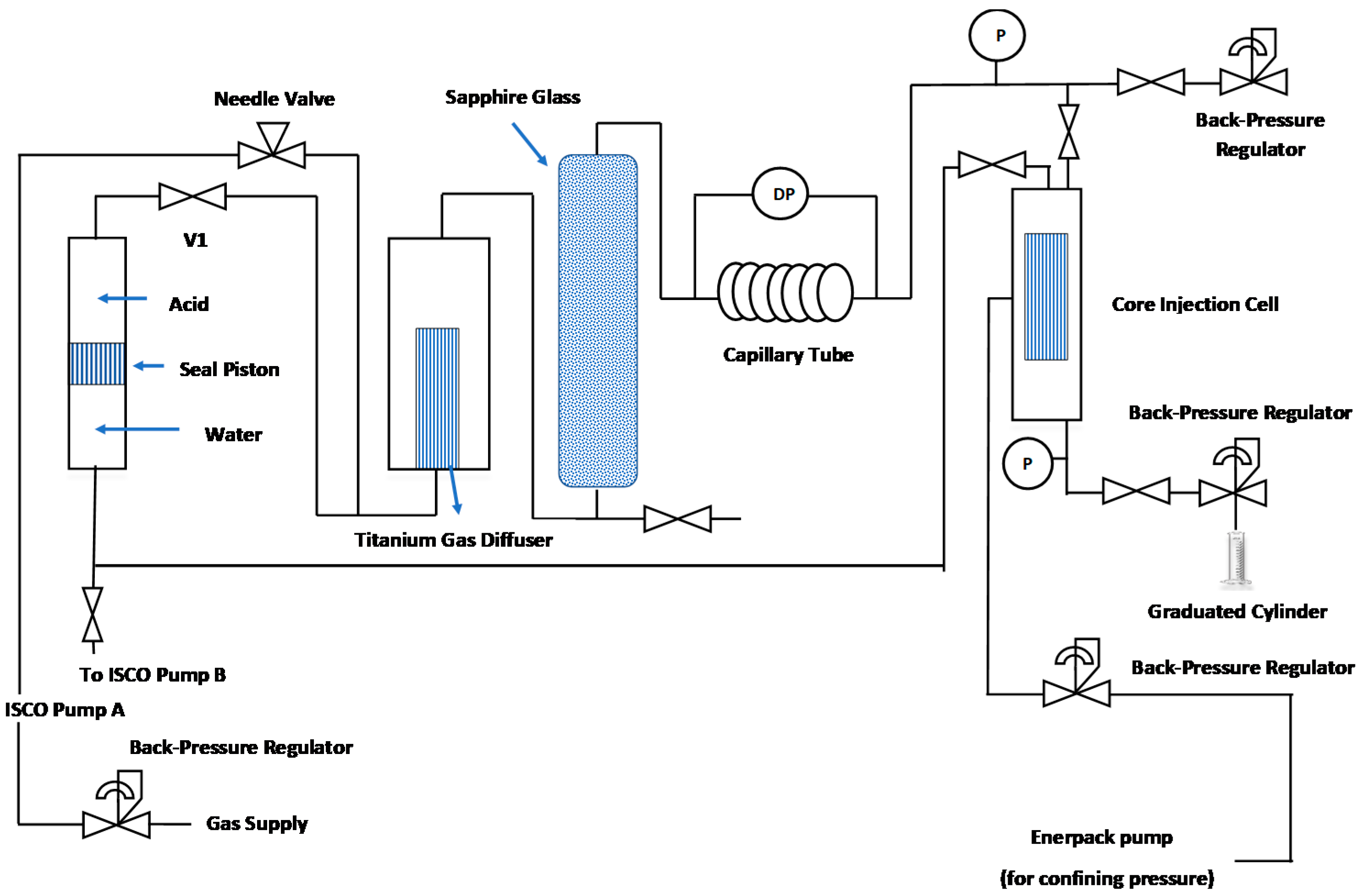
2.1. Experimental Apparatus

The experimental apparatus was developed for conducting foam-stability and wormhole-propagation tests. Figure 1 presents the schematic of the experimental apparatus. The equipment consisted of injection pumps, a gas diffuser, sapphire glass cell, core cell, pressure maintenance system, heating system, and data acquisition system. The acid and CO2 gas were injected at a constant flow rate through ISCO 100D Teledyne pumps. The CO2 foamed acid was developed by mixing the surfactant, CO2 gas, and HCl in a titanium gas diffuser of size, 10 μm. The foam stability tests were conducted using a sapphire glass cell, with a width and length of 40 and 145 mm, respectively. In order to perform wormhole-propagation tests, the CO2 foamed acid flowed from the sapphire glass cell to the core cell. The inner diameter of the core cell was 38 mm, and a core with a maximum length of 60 mm could be installed. The pressure of the core holder could be maintained up to 2000 psi using a back-pressure regulator. The HPHT experimental apparatus was developed to increase an experimental temperature to 176 °C using the heating system. Using this apparatus, the foam-stability and wormhole-propagation tests can be performed under HPHT conditions.
In this study, thin section observation and petrography analysis were conducted to investigate the changes in the rock and mineral properties of the core samples before and after the wormhole-propagation tests. The SEM analysis was conducted using a JSM-6390LA system from JEOL. The apparatus has a high resolution of 3.0 nm and can accommodate specimens with diameters of up to 152 mm. The micro-XRD measurements were performed using a Rigaku Smart Lab 9 kW. The XRD system has a unique five-axis θ–θ goniometer with a horizontal sample mounting. The minimum X-ray spot size of the XRD system is 300 μm. Petrography analysis was conducted using an Imager A2 system from ZEISS to evaluate changes in the pore sizes by CO2 foamed acid injection. The Somatom system from Siemens was used to capture the CT images of the core samples. The temporal resolution of the CT scanner is 125 ms and the image matrix is 512 × 512 pixels.

2.2. Material

Table 1 presents the five surfactants used in the CO2 foamed acid experiment. Amphitol 20 HD, classified as an amphoteric surfactant, was provided by Kao Indonesia Chemicals and consists of 30% lauryl hydroxysultaine. Neopelex FS, alkyl (C10-16) benzenesulfonic acid, was also provided by Kao Indonesia Chemicals. AkzoNobel supplied surfactants of Aromox C/12 W (Cocobis(2-hydroxyethyl)amine oxide) and Ampholak YJH 40 (Octyl iminodipropionate). Aromox C/12 W with an amide oxide content of 32% is classified as a nonionic surfactant, whereas Ampholak YJH 40 has amphoteric surfactant characteristics. Trimax mixed with amphoteric surfactants with amine oxide was purchased from Tritunggal Arthamakmur, Indonesia. To generate the CO2 foamed acid, the surfactant was mixed with CO2 gas, HCl, and a corrosion inhibitor (JM 100 ACI, JM Mutu Company, Banten, Indonesia). The purity of the CO2 gas was 99.999%. The initial concentration of the HCl was 32 wt% and it was adjusted to the concentration required for the experiments by dilution in deionized water.
Two types of limestone core samples were prepared for the wormhole-propagation tests, namely Indiana and Indonesian limestones. Table 2 shows the characteristics of limestome core samples used in wormhole propagation tests. The core samples had diameters of 3.8 cm and lengths ranging from 3–4.7 cm. The Indiana limestones from the Mississippian formation had high purities with calcite compositions of 99%. The permeabilities of the Indiana limestones ranged from 4 to 16 md and they had porosities of 16%. Indonesian limestones, such as SNR-5 and SNR-6, were collected from the Banggai Basin, Sulawesi island, Indonesia. The permeabilities of the Indonesian limestones ranged from 4 to 23 md. The calcite compositions of SNR-5 and SNR-6 were 92% and 96%, respectively, and the purities were lower than those of the Indiana limestones.

2.3. Experimental Procedure

The experimental procedure for evaluating the performance of the CO2 foamed acid is shown in Figure 2 and comprised the following steps: (1) surfactant screening tests, (2) foam stability analysis, (3) matrix acidizing tests, and (4) measurement of rock and mineral properties.
Surfactant screening tests were performed to analyze the influence of the surfactant type on the generation of CO2 foamed acid. Each surfactant shown in Table 1 was mixed with HCl, a corrosion inhibitor, and CO2 to prepare foamed acid. The concentrations of the HCl used to prepare foamed acid were 10% and 20%. The foam decay times were measured under atmospheric conditions (14.7 psi, 20 °C). In this study, foam decay time was defined as the time required for the foam height to decrease from the initial height to zero. Therefore, it is necessary to measure the initial foam height after foam generation and the time it takes for the foam height to reach zero. The foam decay time was dependent on the foam characteristics, such as foam texture, liquid film thickness, and foam drainage rate. From the surfactant screening test, two surfactants with high foam decay times were selected.
The experimental conditions of the foam stability analysis are shown in Table 3. The surfactants selected from the screening tests were mixed to improve the stability of the CO2 foamed acid. The experimental temperature and pressure were 176 °C and 1100 psi, respectively. Thus, the experiments were performed under the supercritical CO2 condition. The experimental parameters were the HCl concentration, surfactant mixing ratio, and foam quality. The HCl concentration range was 10–20%, and the surfactant mixing ratios were 10%:10% and 30%:30%. The foam quality is defined as the ratio of the gas volume to the liquid and gas volume, as expressed by Equation (1). The gas–liquid mixtures are classified by quality: dispersions (Γ < 52%), wet foam (52% < Γ < 74%), dry foam (74% < Γ < 96%), and mist (Γ > 96%) [37]. The foam with a quality of 60% or more exhibits a high performance in the matrix acidizing of carbonate reservoirs [38]. The foam quality was controlled by the injection rate of HCl with the surfactant mixture. The foam qualities at injection rates of 5, 10, and 15 cc/min were 91%, 83%, and 77%, respectively. As shown in Table 3, the HCl concentration and surfactant mixing ratio have 2 levels, whereas injection rate of HCl associated with foam quality has 3 levels. Considering the levels of experimental parameters (2 × 2 × 3), 12 surfactant mixtures were prepared to conduct the foam stability tests under the HPHT conditions.
Γ   = V G V G + V L × 100 ,
where VG is the gas volume at the given temperature and pressure, VL is the liquid volume at the given temperature and pressure, and Γ is the foam quality [%].
Wormhole-propagation tests with CO2 foamed acid were performed using the developed experimental device. The surfactant mixture that was suitable for the tests was selected from the results of the foam-stability analysis. Wormhole-propagation tests using the four carbonate core samples were performed at a temperature of 176 °C and pressure of 1100 psi. The CO2 foamed acid generated in a 10-μm titanium gas diffuser was injected into the limestone core samples. The pressures at the inlet and outlet of the core holder, in addition to the injection flow rate of the foamed acid, were continuously measured during the injection of the CO2 foamed acid. When HCl was injected into carbonate rocks, the following reaction occurred:
Calcite: CaCO3 + 2HCl → CaCl2 + CO2 + H2O,
Dolomite: CaMg(CO3)2 + 4HCl → CaCl2 + MgCl2 + 2CO2 + H2O,
In matrix acidizing, wormholes are formed owing to the chemical reactions between acid and carbonate rock, as expressed by Equations (2) and (3). The wormhole significantly increases the permeability and porosity of the reservoir. Therefore, the performance of CO2 foamed acid can be analyzed by comparing the permeability and porosity before and after matrix acidizing. The pore volume to breakthrough (PVBT) value was calculated based on the data measured in the matrix acidizing test. The wormhole-propagation characteristics were analyzed through CT scans.
Petrophysical properties, such as the pore-size distribution and mineralogy, can be changed by the chemical reaction between acid and carbonate rock. The rock and mineral properties before and after the matrix acidizing tests were analyzed by conducting SEM–EDX and thin-section analyses. The samples for the SEM–EDX analysis were cleaned using organic solvents and ultrasonic treatment. The samples were electrostatically coated with both carbon and gold alloy using JEOL JFC-1600 auto fine coater and JEOL JFC-560.
All the samples were examined using a JEOL JSM-6390-LA SEM scheme equipped with a digital image recording and processing system. In the SEM analysis, the maximum magnification was approximately 10,000×. The thin sections were prepared by acquiring samples from the original limestone cores and were injected with blue-dyed epoxy resin to maintain the natural porosities of the rock samples and allow for the identification of their porosities under a polarization microscope using Zeiss Imager A2.

3. Results

3.1. Surfactant Screening Tests

The CO2 foamed acids were prepared in consideration of various surfactant types and HCl concentrations, and surfactant screening tests were performed under atmospheric conditions. To prepare CO2 foamed acid, each surfactant in Table 1 was mixed with HCl concentrations of 10% and 20%. The foam decay time is an index indicating the foam quantity. The performance of the surfactant increased as the foam decay time increased.
Figure 3 presents the foam decay times of five types of surfactants according to the HCl concentration. The foam decay time of Surfactant A was 1.4 min under the HCl concentration of 10%, and increased to 4 min at the 20% of HCl concentration. As shown in Figure 3, the foam decay time of Surfactant A is significantly lower than that of other surfactants. In the case of Surfactant B, the foam decay times of 22 min and 15 min were measured under HCl concentration of 10% and 20%, respectively. The foam decay time of Surfactant C was shortened from 15 min to 5.5 min as the HCl concentration increased. Thus, the CO2 foam stability of Surfactant C decreased by 63% because of HCl concentration. Surfactant D also showed similar results to Surfactant C, and as the HCl concentration increased, the foam stability decreased by 78%. In Surfactant E, a blend of nonionic surfactant and amphoteric surfactant, the foam decay times were measured to be 14 min and 9.5 min at the HCl concentrations of 10% and 20%, respectively. The decrease in the foam stability of Surfactant E according to the HCl concentration was 32%, which was significantly lower than that of other surfactants.
As shown in the results of surfactant screening tests, the concentration of HCl is one of the important factors that can affect the foam stability of CO2 foamed acid. The reason that the foam decay time decreases as the HCl concentration increases can be explained by the effect of pH. Kovisuith [39] analyzed the effect of pH on foam durability with nonionic surfactant and anionic surfactant. In the nonionic surfactant, the pH change did not have a significant impact, but in the anionic surfactant, the foam durability decreased as the pH of the solution decreased. Liu [40] explained that the surface potential and total interaction potential are a function of the pH of the solution [39,40]. When the surface charge of surfactant is negative, the zeta potential increases and the total interaction decreases as the pH decreases. Therefore, it can be analyzed that Surfactant C is more sensitive to pH change than Surfactant B. The amphoteric surfactants (Surfactants A and D) used in the screening test are highly affected by pH of the solution. Thus, the decay time of Surfactant A was the shortest at an HCl concentration of 10%, and the decay time of Surfactant D was shortest at an HCl concentration of 20%. Surfactant E contained not only amphoteric surfactant, but also nonionic surfactant. Compared to surfactants A and D, Surfactant E was less affected by pH of the solution because nonionic surfactant has no charge on hydrophilic end. For this reason, the foam decay time decreased by 32% as the HCl concentration increased. As shown in Figure 3, the decay times of Surfactants B and E were longer than those of the other surfactants at all the HCl concentrations. At an HCl concentration of 10%, the decay time of Surfactant C was 1 min longer than that of Surfactant E. However, at an HCl concentration of 20%, the decay time of Surfactant E was approximately twice as long as that of Surfactant C. Hence, the foam quality of CO2 foamed acid using Surfactant E was higher than that of Surfactant C.

3.2. Foam Stability Analysis of Supercritical CO2 Foamed Acid

A foam stability analysis was performed under the HPHT conditions using Surfactants B and E, as selected in the surfactant screening test. As shown in Table 3, the foam quality of the supercritical CO2 foamed acid was analyzed according to HCl concentration, surfactant mixing ratio, and injection rate of HCl. Figure 4 presents the foam decay time of the supercritical CO2 foamed acid under various experimental conditions. When the mixing ratio of Surfactants B and E was 10%:10% and the concentration of HCl was 10%, the foam decay time at the foam quality of 91% was measured to be 1.38 h. As the HCl concentration increased to 20%, the foam decay time increased to 5.47 h. When the surfactant mixing ratio was 30%:30%, the foam decay time increased from 3.46 h to 7.34 h as the HCl concentration increased. The results of the foam stability tests indicate that the HCl concentration and surfactant mixing ratio had a positive influence on the foam decay time under HPHT conditions. The increase in surfactant mixing ratio means the increase in surfactant concentration. Therefore, the foam decay time was proportional to the surfactant concentration under the same conditions of HCl concentration and foam quality. The foam stability of the surfactant mixture increased as the HCl concentration increased. It is expected that changes in physical properties of foam, such as the dispersion of fluid and micellar aggregates with increasing HCl concentration, will lead to the increase in foam decay time. Since the CO2 foamed acid was stably maintained at high HCl concentration, the efficiency of matrix acidizing can be improved by using surfactant mixture of Surfactants B and E. As a future study, the effect of HCl concentration on surfactant mixture will be analyzed in detail through additional experiments such as foam morphology analysis using optical microscopy, apparent viscosity tests, and surface tension measurement.
The foam decay time decreased as the injection rate of HCl increased from 5 to 15 cc/min in all the experimental cases. The highest foam decay time was observed when the injection rate of HCl was 5 cc/min. As the injection rate of HCl increased, the foam decay time decreased due to the foam texture. A fine foam texture was produced at low HCl injection rates, whereas a coarse foam texture was produced at high injection rates. A fine texture can better maintain the stability of the foam than a coarse texture. Therefore, it is necessary to consider the influences of the HCl concentration, surfactant mixing ratio, and HCl injection rate to evaluate the foam quality of the supercritical CO2 foamed acid. Based on the results of the foam stability analysis under HPHT conditions, the foam stability can be improved by adding a surfactant mixture to an HCl concentration of 20%.

3.3. Wormhole-Propagation Tests

The wormhole-propagation tests were conducted to analyze the matrix acidizing efficiency of the CO2 foamed acid. To analyze the injectivity of the CO2 foamed acid, preliminary tests were performed using foamed acids with an HCl concentration of 20% and surfactant mixing ratios of 10%:10% and 30%:30%. In the foam-stability analysis, the CO2 foamed acid with an HCl concentration of 20% and surfactant mixing ratio of 30%:30% exhibited the highest stability. However, the fluid was not stably injected into the core sample in the preliminary tests due to low injectivity. The 20% HCl concentration with surfactant mixing ratio of 10%:10% and foam quality of 91% was used as the experimental fluid for the wormhole-propagation tests. The experiments using Indiana and Indonesian limestones were carried out at a temperature of 176 °C and pressure of 1100 psi. The injection rates of CO2 and HCl were 50 and 5 cc/min, respectively. The time required to create a wormhole and PVBT were analyzed by measuring the differential pressure between the inlets and outlets of the core samples.
Table 4 presents the characteristics of the limestone core samples before and after the wormhole-propagation tests. The porosity of the Indiana limestone before CO2 foamed acid injection was 15%, and the porosity of the Indonesian limestone was approximately 24%. The permeabilities of Plug 8 and Plug 12 were measured as 9.63 and 4.96 md, respectively. The SNR-5 had a permeability of 22.04 md, and that of SNR-6 was 4.11 md. Wormholes change the permeability and porosity of carbonate rock. As shown in Table 4, the porosities of Plug 8 and Plug 12 increased by approximately 1%, and the porosities of SNR-5 and SNR-6 increased by 1.67% and 2.35%, respectively. Given that the wormhole was formed after the injection of CO2 foamed acid, the permeability increased up to 38,123 md.
The PVBT is an index that determines the efficiency of matrix acidizing. It indicates the total amount of acid injected until the wormhole is formed, divided by the pore volume. As the PVBT decreased, the total amount of acid required for wormhole generation decreased. At low PVBT values, the cost-effectiveness of matrix acidizing can be improved. The PVBT of the Indiana limestone ranged from 7.15 to 7.32, as shown in Table 4. The PVBT of SNR-5 was calculated as 8.12, whereas that of SNR-6 was calculated as 7.53. The influence of the initial permeability on the PVBT was analyzed. The injection of the supercritical CO2 foamed acid was more efficient when the permeability was low for the same limestone sample.
Figure 5 presents images of the inlet and outlet of each core sample after the injection of CO2 foamed acid. As shown in Figure 5, the wormhole was formed from the inlet to the outlet. The CT scanning was carried out to analyze the propagation characteristics of the wormhole. Figure 6 presents the CT scanning results of Plug 12 and SNR-6. Two dissolution channels were observed at the inlet of Plug 12. The dissolution channel on the left side formed a dominant wormhole penetrating the core sample. The flow direction of the CO2 foamed acid changed as the wormhole was twisted at a quarter of Plug 12. The wormhole diameter at the inlet of Plug 12 was 3.1 mm, while the diameter at the outlet decreased to 2.1 mm. The wormhole diameter decreased because the dissolution rate of the injected acid decreased due to the continuous acid-rock reaction in the process of forming the dominant wormhole. In the case of SNR-6, the dominant wormhole was formed from the inlet to the outlet without the torsion of the dissolution channel. The wormhole diameters at the inlet and outlet of SNR-6 were 3.8 mm and 3.1 mm, respectively, and the diameter decreased due to the reduction of dissolution rate. As shown in Figure 6, the dominant wormholes were formed in both limestone cores by the injection of CO2 foamed acid. Therefore, the supercritical CO2 foamed acid with surfactant mixture of Surfactants B and E can help to carry out carbonate matrix acidizing under the HPHT conditions.

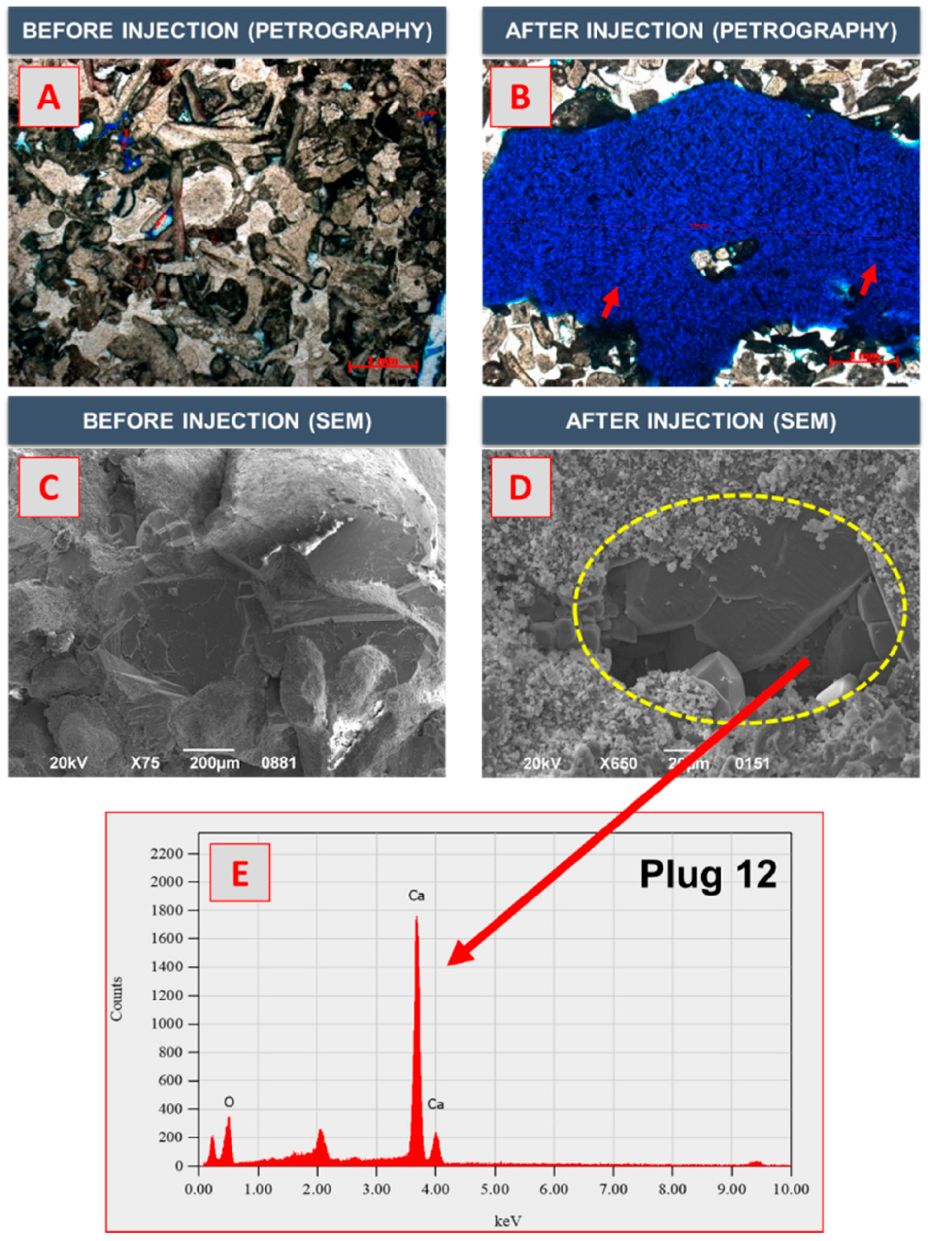
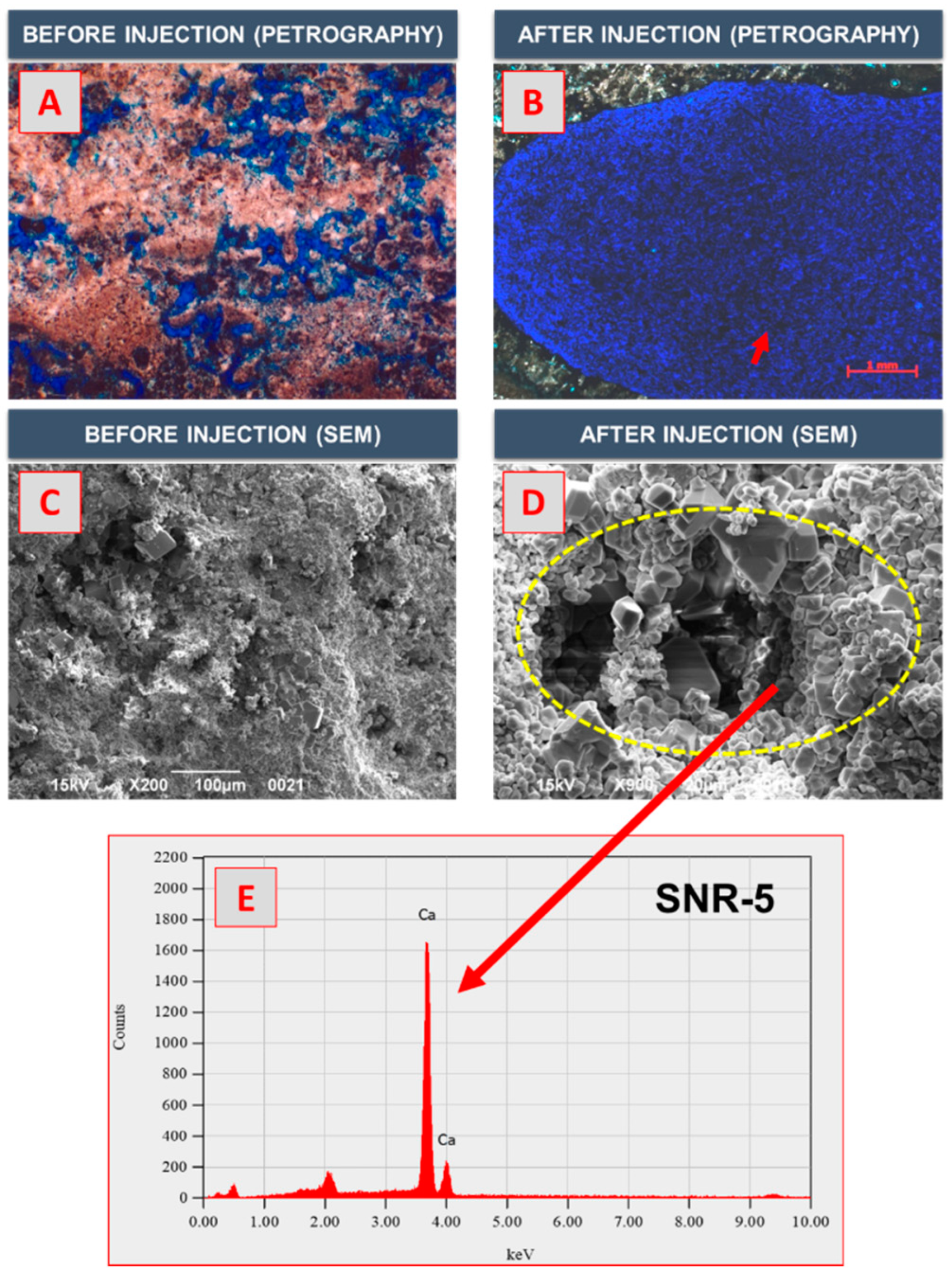
3.4. SEM–EDX and Thin-Section Analyses

The wormhole can be formed by a chemical reaction between acid and carbonate rock. The SEM–EDX and thin-section analyses were performed to analyze the petrophysical properties according to the reaction of CO2 foamed acid and carbonate rock at a microscale. Figure 7 presents the petrography and SEM photomicrographs of Plug 8. The blue area in Figure 7A indicated pores, and the pore size of Plug 8 before CO2 foamed acid injection was 0.3 mm. After the injection of the foamed acid, the pore size was expanded as micritic crystals were dissolved. The pore size in Figure 7B was 6.66 mm, and maximum pore size of 22.10 mm was observed. As the pore size increased, permeability increased from 9.63 md to 38,123 md. In the case of porosity, it increased from 15.4% to 16.4%. The rock dissolution by CO2 foamed acid can be identified from SEM images before and after matrix acidizing treatment. The magnification of Figure 7C,D were 40× and 200×, respectively. The yellow circle in Figure 7D shows the dissolution part due to CO2 foamed acid injection. Figure 7E shows the result of EDX analysis in the yellow circle in Figure 7D, showing the intensity versus energy. From the EDX analysis results for Plug 8, calcium (Ca) is the main component. Thus, no changes in the mineral composition were observed after treatment due to the high purity of the Indiana limestone.
The similar results to Plug 8 were observed in the results of SEM–EDX and thin section analyses of Plug 12. As shown in Figure 8A,B, the pore size of Plug 12 increased from 0.44 mm to 6.54 mm. The pore size in the entire sample of Plug 12 increased up to 16.35 mm after the injection of CO2 foamed acid. The SEM photomicrographs of Plug 12 show that the dissolution of carbonate rock occurred by acid-rock reaction. Given that the calcite content was dominant, there were no significant changes in the mineral composition of Indiana limestone cores.
The results of SEM–EDX and thin section analyses for Indonesia limestone samples are shown in Figure 9 and Figure 10. The maximum pore size of SNR-5 and SNR-6 increased to 14.2 mm and 9.32 mm, respectively. As shown in Figure 10C, foraminifera was observed in the SEM photomicrograph of SNR-6. The SEM photomicrographs show that the pore size increased because of the dissolution of carbonate rock. After matrix acidizing treatment, the porosity and permeability of Indonesia limestone samples increased significantly. From the results of EDX analysis of SNR-5 and SNR-6, no changes in mineral composition were observed.
Table 5 summarizes the results of the pore size distribution before and after the injection of CO2 foamed acid. After the injection of CO2 foamed acid, the number of pores increased due to the acid–rock reaction. The initial pore size of the four samples was less than 1 mm. As shown in Table 5, pore sizes larger than 0.1 mm increased after the injection of CO2 foamed acid. In particular, pore sizes larger than 0.5 mm significantly increased. In Plug 8, the maximum pore size increased from 0.62 to 22.10 mm. The maximum pore size of SNR-6 increased from 0.25 to 4.32 mm. Thus, the influence of the CO2 foamed acid injection is clearly observed. In summary, the results of the core flooding tests and petrography analysis revealed that the CO2 foamed acid prepared using the surfactant mixture exhibited a high efficiency of matrix acidizing under HPHT conditions.

4. Conclusions

In this study, an experimental apparatus was developed to conduct tests on foam stability and wormhole propagation under HPHT conditions. The CO2 foamed acid with a high stability was generated using a surfactant mixture, and the efficiency of matrix acidizing was analyzed by conducting wormhole-propagation tests. The following conclusions can be drawn from the results of this study.
(1)
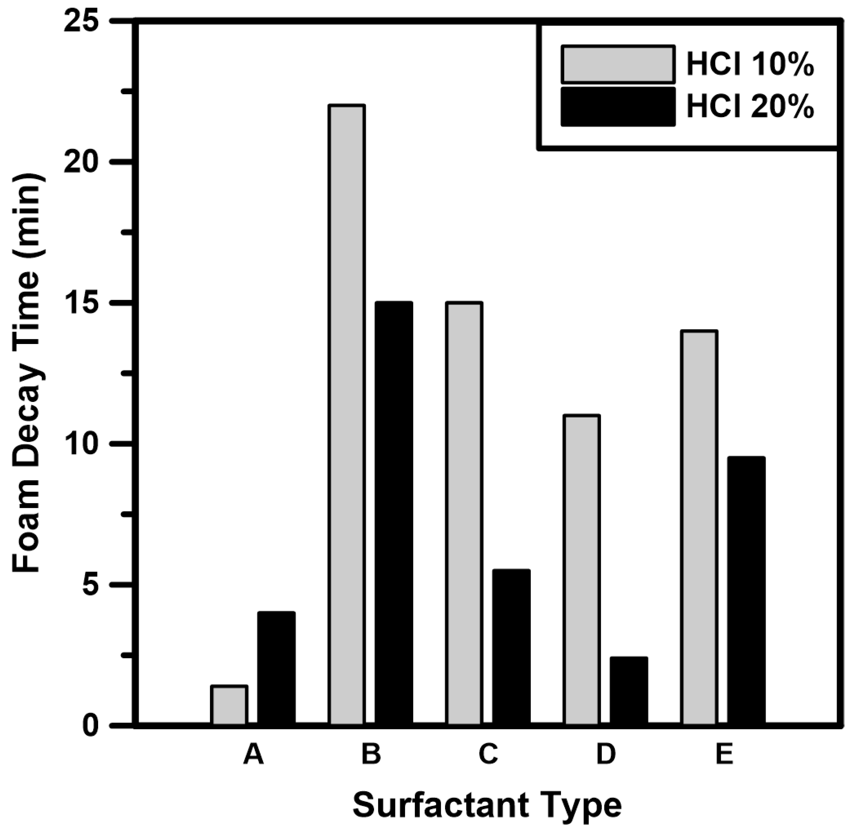
The foam decay times of five types of surfactants were measured under atmospheric conditions. Based on the surfactant screening test results, Surfactant B (nonionic surfactant) and Surfactant E (nonionic-amphoteric surfactant) exhibited high stability because the nonionic surfactant had no charge on the hydrophilic end. Therefore, the surfactant mixture prepared by mixing two surfactants can improve the foam stability of CO2 foamed acid.
(2)
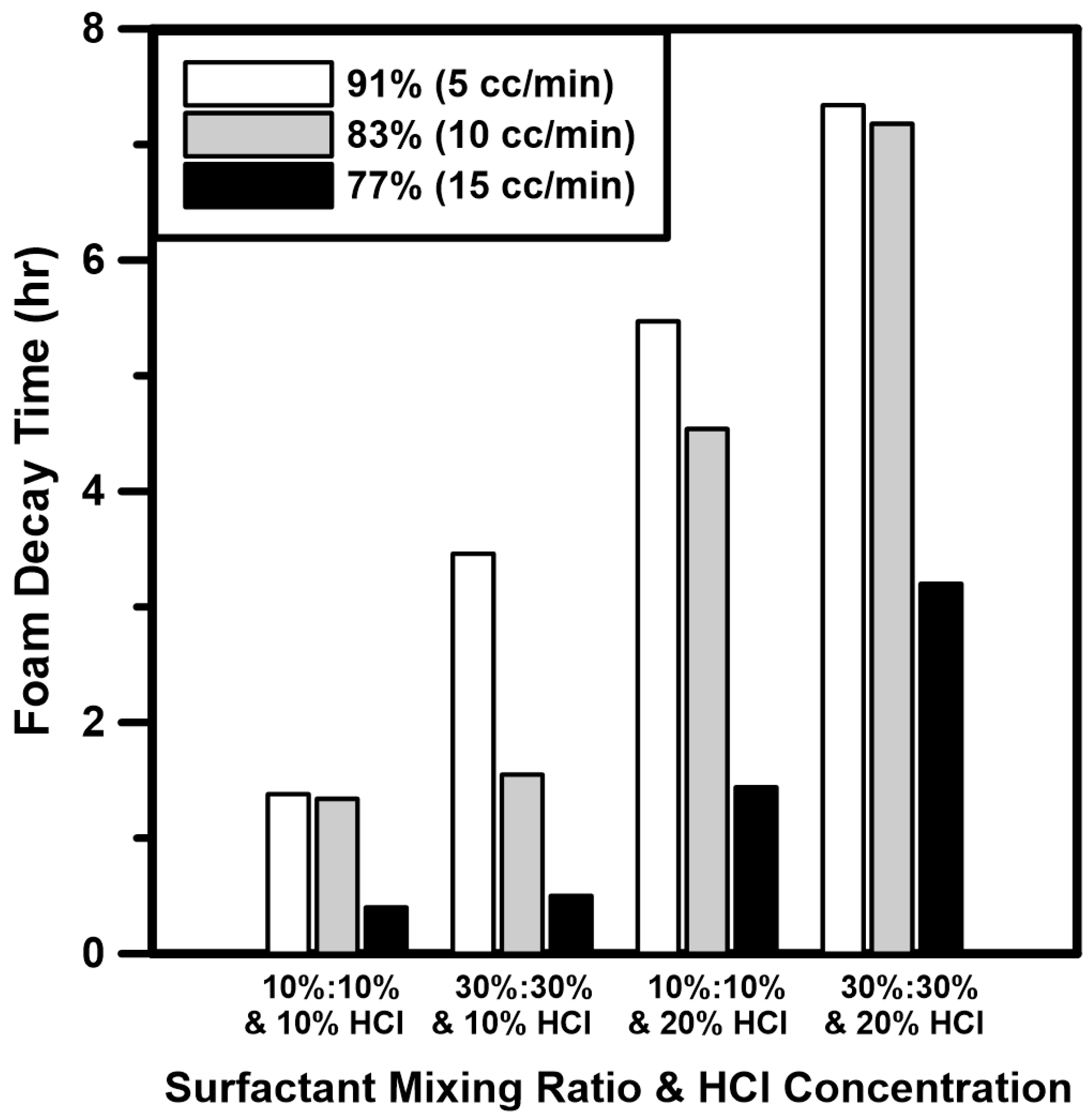
Foam quality tests of CO2 foamed acid using a surfactant mixture were performed under HPHT conditions. The HCl concentration and surfactant mixing ratio had a positive influence on the foam stability. In the case of foam quality, foam stability was high because the fine foam texture was produced at low injection rate of HCl. From the analysis results, the foam stability was considerably improved by adding the surfactant mixture to an HCl concentration of 20%.
(3)
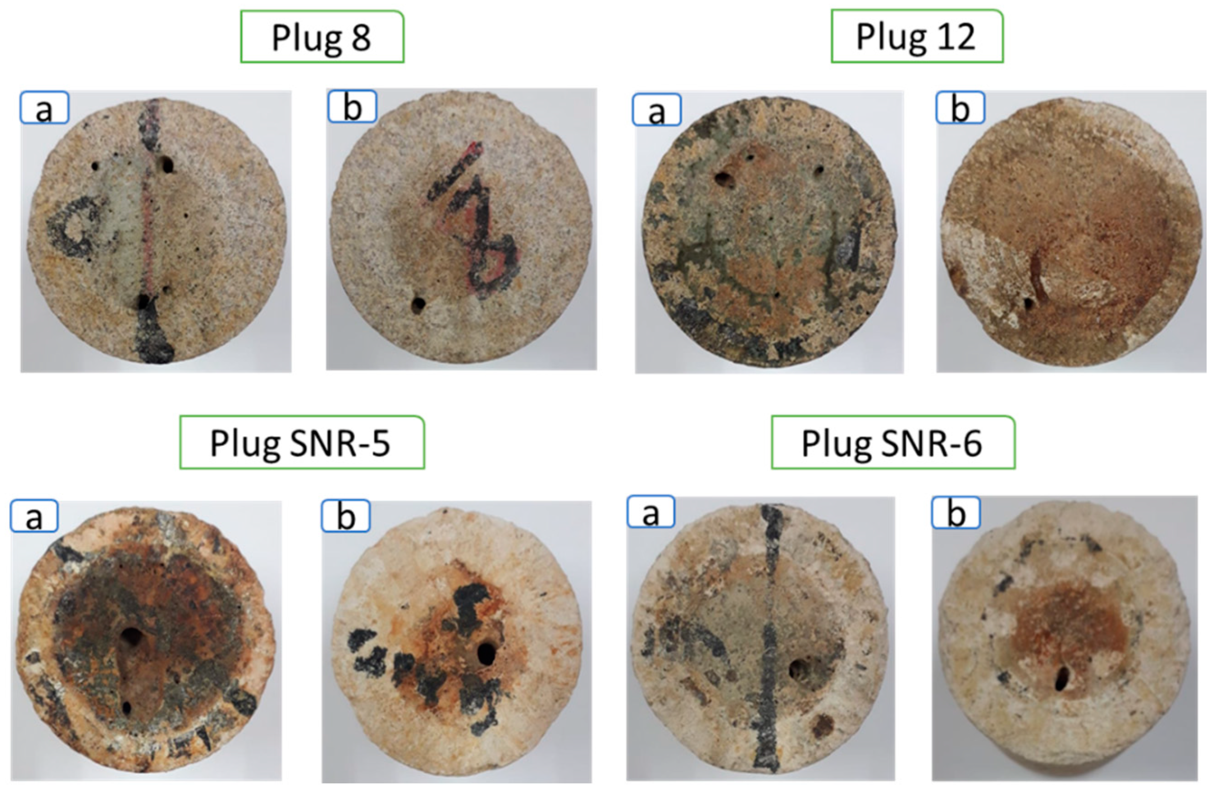
The wormhole-propagation tests were conducted using Indiana and Indonesia limestones. After the injection of CO2 foamed acid, the permeabilities of the limestone cores significantly increased as wormholes were formed. While the CO2 foamed acid flowed from the inlet to the outlet of the core, the diameter of the wormhole gradually decreased due to the reduction of acid dissolution rate. The PVBT analysis results showed that the supercritical CO2 foamed acid was more efficient in cores with low permeabilities.
(4)
The results of the SEM–EDX and thin-section analyses revealed that as the number of large pores with pore sizes of ≥0.5 mm increased, the maximum pore size increased by a factor of 33 on average. Therefore, the supercritical CO2 foamed acid with surfactant mixture exhibited a high efficiency of matrix acidizing. Further research is required to optimize the injection rate of CO2 foamed acid by conducting experiments on the influencing factors of the PVBT by using the developed experimental apparatus.

Author Contributions

All authors contributed to the research in this paper. Conceptualization, R.K. and W.L.; methodology, R.K.; software, R.K. and Y.K.; validation, R.K., Y.K. and W.L.; formal analysis, R.K.; investigation, R.K.; resources, R.K.; data curation, R.K. and Y.K.; writing—original draft preparation, R.K.; writing—review and editing, Y.K. and W.L.; visualization, Y.K.; supervision, W.L.; project administration, W.L.; funding acquisition, W.L. All authors have read and agreed to the published version of the manuscript.

Funding

This research funded by [the Ministry of Trade, Industry and Energy (MOTIE), Korea], [the Gas Hydrate R&D Organization (GHDO)], [the Korea Institute of Geoscience and Mineral Resources (KIGAM)] grant number [GP2021-011].

Institutional Review Board Statement

Not applicable.

Informed Consent Statement

Not applicable.

Data Availability Statement

The data presented in this study are available on request from the corresponding author. The data are not publicly available due to confidentiality.

Acknowledgments

This study was supported by the Ministry of Trade, Industry and Energy (MOTIE), Korea, the Gas Hydrate R&D Organization (GHDO), and the Korea Institute of Geoscience and Mineral Resources (KIGAM) (GP2021-011).

Conflicts of Interest

The authors declare no conflict of interest.

References

  1. Yoo, H.; Kim, Y.; Lee, W.; Lee, J. An experimental study on acid-rock reaction kinetics using dolomite in carbonate acidizing. J. Pet. Sci. Eng. 2018, 168, 478–494. [Google Scholar] [CrossRef]
  2. Liu, X.; Ormond, A.; Bartko, K.; Li, Y.; Ortoleva, P. A geochemical reaction-transport simulator for matrix acidizing analysis and design. J. Pet. Sci. Eng. 1997, 17, 181–196. [Google Scholar] [CrossRef]
  3. Bernadiner, M.G.; Thompson, K.E.; Fogler, H.S. Effect of foams used during carbonate acidizing. SPE Prod. Eng. 1992, 7, 363–370. [Google Scholar] [CrossRef]
  4. Lund, K.; Fogler, H.S.; McCune, C.C.; Ault, J.W. Acidization-II. The dissolution of calcite in hydrochloric acid. Chem. Eng. Sci. 1975, 30, 825–835. [Google Scholar] [CrossRef] [Green Version]
  5. Gomaa, A.M.; Cutler, J.; Qu, Q.; Cawiezel, K.E. Acid placement: An effective VES system to stimulate high-temperature carbonate formations. In Proceedings of the SPE International Production and Operations Conference and Exhibition, Doha, Qatar, 14–16 May 2012. [Google Scholar]
  6. Zhang, L.; He, J.; Wang, H.; Li, Z.; Zhou, F.; Mou, J. Experimental investigation on wormhole propagation during foamed-VES acidizing. J. Pet. Sci. Eng. 2021, 198, 108139. [Google Scholar] [CrossRef]
  7. Yuan, H.; Chen, X.; Li, N.; Zhou, H.; Gong, Y.; Wang, Y. Numerical simulation of foam diversion acidizing in heterogeneous reservoirs. Petroleum 2021, in press. [Google Scholar] [CrossRef]
  8. Alawi, M.B.; Hassan, A.; Aljawad, M.S.; Kamal, M.S.; Mahmoud, M.; Al-Nakhli, A. A novel approach to improve acid diversion in carbonate rocks using thermochemical fluids: Experimental and numerical study. Molecules 2020, 25, 2976. [Google Scholar] [CrossRef]
  9. Buijse, M.A.; Van Domelen, M.S. Novel application of emulsified acids to matrix stimulation of heterogeneous formations. SPE Prod. Oper. 2000, 15, 208–213. [Google Scholar] [CrossRef]
  10. Eoff, L.; Dalrymple, D.; Reddy, B.R. Development of associative polymer technology for acid diversion in sandstone and carbonate lithology. SPE Prod. Oper. 2004, 20, 250–256. [Google Scholar] [CrossRef]
  11. Lungwitz, B.; Fredd, C.; Brady, M.; Miller, M.; Ali, S.; Hughes, K. Diversion and Cleanup Studies of Viscoelastic Surfactant-Based Self-Diverting Acid. SPE Prod. Oper. 2007, 22, 121–127. [Google Scholar] [CrossRef]
  12. Nasr-El-Din, H.A.; Al-ghamdi, A.H.; Al-Qahtani, A.A.; Samuel, M.M. Impact of acid additives on the rheological properties of viscoelastic surfactants and their influence on field application. SPE J. 2008, 13, 35–47. [Google Scholar] [CrossRef]
  13. Farajzadeh, R.; Andrianov, A.; Bruining, H.; Zitha, P.L.J. New insights into application of foam for acid diversion. In Proceedings of the SPE European Formation Damage Conference, Scheveningen, The Netherlands, 27–29 May 2009. [Google Scholar]
  14. Ford, W.G.F. Foamed Acid, an Effective Stimulation Fluid. J. Pet. Technol. 1981, 33, 1203–1210. [Google Scholar] [CrossRef]
  15. Rahmani, O. Mobility control in carbon dioxide-enhanced oil recovery process using nanoparticle-stabilized foam for carbonate reservoirs. Colloids Surfaces A Physicochem. Eng. Asp. 2018, 550, 245–255. [Google Scholar] [CrossRef]
  16. Czupski, M.; Kasza, P.; Lesniakl, U. Development of selective acidizing technology for an oil field in the zechstein main dolomite. Energies 2020, 13, 5940. [Google Scholar] [CrossRef]
  17. Cheng, L.; Kam, S.I.; Delshad, M.; Rossen, W.R. Simulation of Dynamic Foam-Acid Diversion Processes. SPE J. 2001, 7, 316–324. [Google Scholar] [CrossRef]
  18. Bybee, K. Acid placement and diversion. J. Pet. Technol. 2010, 62, 53–54. [Google Scholar] [CrossRef]
  19. Al-Ghamdi, A.H.; Mahmoud, M.A.; Wang, G.; Hill, A.D.; Nasr-El-Din, H.A. Acid diversion by use of viscoelastic surfactants: The effects of flow rate and initial permeability contrast. SPE J. 2014, 19, 1203–1216. [Google Scholar] [CrossRef]
  20. Hematpur, H.; Mahmood, S.M.; Nasr, N.H.; Elraies, K.A. Foam flow in porous media: Concepts, models and challenges. J. Nat. Gas Sci. Eng. 2018, 53, 163–180. [Google Scholar] [CrossRef]
  21. Yan, Y.L.; Xi, Q.; Una, C.C.; He, B.C.; Wu, C.S.; Dou, L.L. A novel acidizing technology in carbonate reservoir: In-Situ formation of CO2 foamed acid and its self-diversion. Colloids Surfaces A Physicochem. Eng. Asp. 2019, 580, 123787. [Google Scholar] [CrossRef]
  22. Solbakken, J.S.; Skauge, A.; Aarra, M.G. Supercritical CO2-foam—The importance of CO2 density on foams performance. In Proceedings of the SPE Enhanced Oil Recovery Conference, Kuala Lumpur, Malaysia, 2–4 July 2013; pp. 1–16. [Google Scholar]
  23. Karadkar, P.; Bataweel, M.; Bulekbay, A.; Alshaikh, A.A. Energized fluids for upstream production enhancement: A review. In Proceedings of the SPE Kingdom of Saudi Arabia Annual Technical Symposium and Exhibition 2018, Dammam, Saudi Arabia, 23–26 April 2018; pp. 1–26. [Google Scholar]
  24. Schramm, L.L.; Wassmuth, F. Foams: Basic Principles. In Foams: Fundamentals and Applications in the Petroleum Industry; American Chemical Society: Washington, DC, USA, 1994; Volume 242, pp. 3–45. [Google Scholar]
  25. Andrianov, A.; Farajzadeh, R.; Mahmoodi Nick, M.; Talanana, M.; Zitha, P.L.J. Immiscible foam for enhancing oil recovery: Bulk and porous media experiments. Ind. Eng. Chem. Res. 2012, 51, 2214–2226. [Google Scholar] [CrossRef]
  26. Almobarky, M.A.; Yousef, Z.A.I.; Schechter, D. Comparing two anionic surfactants for mobility control with Supercritical CO2 in miscible EOR. In Proceedings of the Carbon Management Technology Conference, Houston, TX, USA, 17–20 July 2017. [Google Scholar]
  27. Alyousef, Z.A.; Almobarky, M.A.; Schechter, D.S. Surfactant and a mixture of surfactant and nanoparticles stabilized-CO2/brine foam for gas mobility control and enhanced oil recovery. In Proceedings of the Carbon Management Technology Conference, Houston, TX, USA, 17–20 July 2017. [Google Scholar]
  28. Almobarky, M.; AlYousef, Z.; Schechter, D. Enhancing the foam stability using surfactants mixtures. In Proceedings of the SPE Kingdom of Saudi Arabia Annual Technical Symposium and Exhibition 2018, Dammam, Saudi Arabia, 23–26 April 2018. [Google Scholar]
  29. Alli, Y.F.; Damayantri, D.; Irawan, Y. The Effect of Anionic and Nonionic Co-Surfactant for Improving Solubility of Polyoxy-Based Surfactant for Chemical Flooding. Sci. Contrib. Oil Gas 2017, 40, 117–123. [Google Scholar] [CrossRef]
  30. Curbelo, F.D.S.; Garnica, A.I.C.; Castro Dantas, T.N.; Barros Neto, E.L. Synergism Study of Mixtures of Ionic and Nonionic Surfactants in Enhanced Oil Recovery Adsorption. Braz. J. Pet. Gas 2017, 11, 91–97. [Google Scholar] [CrossRef] [Green Version]
  31. Kesarwani, H.; Saxena, A.; Mandal, A.; Sharma, S. Anionic/nonionic surfactant mixture for enhanced oil recovery through the investigation of adsorption, interfacial, rheological, and rock wetting characteristics. Energy Fuels 2021, 35, 3065–3078. [Google Scholar] [CrossRef]
  32. Kumari, R.; Kakati, A.; Nagarajan, R.; Sangwai, J.S. Synergistic effect of mixed anionic and cationic surfactant systems on the interfacial tension of crude oil-water and enhanced oil recovery. J. Dispers. Sci. Technol. 2019, 40, 969–981. [Google Scholar] [CrossRef]
  33. Osei-Bonsu, K.; Shokri, N.; Grassia, P. Foam stability in the presence and absence of hydrocarbons: From bubble- to bulk-scale. Colloids Surfaces A Physicochem. Eng. Asp. 2015, 481, 514–526. [Google Scholar] [CrossRef]
  34. He, K.; Xu, L. Unique mixtures of anionic/cationic surfactants: A new approach to enhance surfactant performance in liquids-rich shale reservoirs. SPE Prod. Oper. 2017, 33, 363–370. [Google Scholar] [CrossRef]
  35. Aveyard, R.; Binks, B.P.; Fletcher, P.D.I.; Peck, T.G.; Rutherford, C.E. Aspects of aqueous foam stability in the presence of hydrocarbon oils and solid particles. Adv. Colloid Interface Sci. 1994, 48, 93–120. [Google Scholar] [CrossRef]
  36. Simjoo, M.; Rezaei, T.; Andrianov, A.; Zitha, P.L.J. Foam stability in the presence of oil: Effect of surfactant concentration and oil type. Colloids Surfaces A Physicochem. Eng. Asp. 2013, 438, 148–158. [Google Scholar] [CrossRef]
  37. Hutchins, R.D.; Miller, M.J. A circulating-foam loop for evaluating foam at conditions of use. SPE Prod. Facil. 2005, 20, 286–294. [Google Scholar] [CrossRef]
  38. Alvarez, J.; Rivas, H.; Navarro, G. An Optimal Foam Quality for Diversion in Matrix-Acidizing Projects. In Proceedings of the SPE International Symposium on Formation Damage Control, Lafayette, Louisiana, 23–27 February 2000. [Google Scholar]
  39. Kovisuith, P. Effects of pH on Surfactant Solutions and Gas on IFT, Foaming, and Adsorption on Rock; New Mexico Institute of Mining and Technology: Socorro, NM, USA, 2009. [Google Scholar]
  40. Liu, Y.; Grigg, R.B.; Bai, B. Salinity, pH, and surfactant concentration effects on CO2-foam. In Proceedings of the SPE International Symposium on Oilfield Chemistry, The Woodlands, TX, USA, 2–4 February 2005; pp. 1–11. [Google Scholar]
Figure 1. Schematic of the experimental apparatus.
Energies 14 06567 g001
Figure 2. Flowchart of the entire experimental process.
Energies 14 06567 g002
Figure 3. Foam decay time of various surfactants under atmospheric conditions.
Energies 14 06567 g003
Figure 4. Foam decay time of surfactant mixture of Surfactants B and E under HPHT conditions.
Energies 14 06567 g004
Figure 5. Wormhole-propagation tests (a) Core inlet (left); (b) outlet (right) after CO2 foamed acid injection.
Energies 14 06567 g005
Figure 6. Computed tomography (CT) scans of limestone core samples after CO2 foamed acid injection.
Energies 14 06567 g006
Figure 7. Results of SEM–EDX and thin-section analyses of Plug 8.
Energies 14 06567 g007
Figure 8. Results of SEM–EDX and thin-section analyses of Plug 12.
Energies 14 06567 g008
Figure 9. Results of SEM–EDX and thin-section analyses of SNR-5.
Energies 14 06567 g009
Figure 10. Results of SEM–EDX and thin-section analyses of SNR-6.
Energies 14 06567 g010
Table 1. List of surfactants used in the CO2 foamed acid experiment.
SymbolModelSurfactantType
AAmphitol 20 HDLauryl hydroxysultaineAmphoteric
BAromox C/12 WCoco bis-(2-hydroxyethyl) amine oxideNonionic
CNeopelex FSAlkyl (C10-16) benzenesulfonic acidAnionic
DAmpholak YJH 40Octyl iminodipropionateAmphoteric
ETrimaxCocamidopropyl betaine, disodium cocoamphodiacetate, and amine oxideNonionic-Amphoteric
Table 2. Characteristics of limestone core samples.
Plug. NoLocation of SamplingDiameter, cmLength, cmCalcite Composition, %
Plug 8Mississippian formation, USA3.7994.69799
Plug 12Mississippian formation, USA3.7264.24699
SNR-5Banggai Basin, Indonesia3.7733.04292
SNR-6Banggai Basin, Indonesia3.7924.16796
Table 3. Experimental conditions for foam stability analysis.
ParametersValues
Pressure, psi1100
Temperature, °C176
HCl concentration, wt%10, 20
Surfactant mixing ratio, %:%10:10, 30:30
Injection rate of HCl, cc/min5, 10, 15
Table 4. Characteristics of limestone core samples before and after CO2 foamed acid injection.
Plug. NoBefore TreatmentAfter TreatmentPVBT
Porosity, %Permeability, mdPorosity, %Permeability, md
Plug 815.409.6316.4038,123.007.32
Plug 1215.074.9616.1129,009.007.15
SNR-524.7522.0426.4236,032.008.12
SNR-623.864.1126.2132,436.007.53
Table 5. Pore size distribution before and after injection of CO2 foamed acid.
Plug. NoPore Size Distribution, mmMaximum Pore Size, mm
<0.10.1–0.250.25–0.50.5–1.0>1.0
Before treatment
Plug 8184116300.62
Plug 12361912100.54
SNR-5162115800.50
SNR-636263100.25
After treatment
Plug 81846184322.10
Plug 123518136116.35
SNR-516231812314.2
SNR-638294259.32
Publisher’s Note: MDPI stays neutral with regard to jurisdictional claims in published maps and institutional affiliations.

