Abstract
In a grid, the choice of the point of common coupling (PCC) does not solely rely on the voltage level alone but also conjointly depends on the grid strength for many explicit purposes. Nowadays, the affinity of low SCR grid connections has become a crucial thought once it involves the integration of wind generation plants (WPPs). Since the quality of wind resources is a critical issue, these plants are usually placed in remote areas with a sophisticated potential of wind flow. These remote areas are typically less inhabited, where the grid does not perpetually always have to be sturdy. Moreover, the exceeded power demand loading and higher wind penetration affect the generation, transmission, and distribution utilities by permitting the flow of unbalanced voltages and currents in the power system. Therefore, the quality of transmitted power is becoming a crucial facet of distributed energy generation units. In this paper, a permanent-magnet synchronous generator (PMSG) based wind energy conversion system (WECS) is presented. It discusses a solution, which provides the low voltage ride through (LVRT) provision by the suppression of DC link overvoltage and active power limitation during an asymmetrical grid fault. With improved back-to-back converter control, the machine side converter (MSC) is employed to control the DC-link voltage. Furthermore, the grid side converter (GSC) is used to implement the active/reactive current injection according to the outlined limits. The need for external hardware is eventually avoided, which is typically required to dissipate the additional energy generated during a grid fault. Hence, it is proven to be an affordable solution.
1. Introduction
The greenhouse emission commencing from the ignition of fossil fuels to harvest electrical energy contributes as the foremost factor in global warming and climate change. In the new era of consumers and power quality, there is a need to install renewable energy resources-based power plants. According to the Pakistan Economic Survey (PES) in 2019–2020, the approximation of installed capacity of power generation in Pakistan is 37,402 MW, the total consumer average demand is 25,000 MW, and the transmission and distribution capacity is 22,000 MW [1]. Pakistan is producing 62% of its energy requirements using conventional resources. To reduce the greenhouse emission effect, there is a need to invest in renewable energy resources, such as photovoltaic, biomass, fuel cells, and wind farms. Wind farms are becoming popular among other renewable energy resources. It is a pollution-free and ecologically pleasant solution, which requires the slightest maintenance. According to Betz’s coefficient, the efficiency of wind energy conversion to electrical energy using a standalone wind turbine is 59% [2]. However, due to wind nonlinearity and consumer demand, there are many coefficients that must be controlled for transmitting power supply to the PCC (point of common coupling). As per recent wind energy conversion system (WECS) technology, different types of generators are used to fulfill these governing criteria. Frequently used generators for wind turbines are the wound-rotor induction generator (WRIG), squirrel-cage induction generator (SCIG), double-fed induction generator (DFIG), and permanent-magnet synchronous generator (PMSG) [3]. PMSG has many benefits over other types of generators, such as being gearbox free, offering high power density, better precision, and requiring modest control techniques for governing. However, PMSG is very expensive and its availability in the larger size (more than 1.5 MW) is not easily available [4,5].
In power transmission, grid faults trigger many complications in a network. To regulate power flow in a PMSG-based WECS, there is a need to deploy back-to-back converters on the grid and generator sides, which assist in regulating the voltages during unbalanced conditions (asymmetrical faults). Generally, a wind farm is a nonlinear energy resource. This is why an automated control strategy is required to maintain constant DC-link voltage during unbalanced conditions to achieve low voltage ride-through (LVRT).
During a very low voltage fault (where the remaining voltage is 10%), the amount of power being transferred from the DC link to the grid drops down because the grid-side converter (GSC) approaches its maximum current limit. However, the generation side keeps on producing electric power. Consequently, the DC link voltage increases significantly and needs to be controlled by limiting the amount of power injected into the grid. The conventional back-to-back converter controllers do not perform sufficiently well to deal with the DC-link overvoltage. Hence, external devices are required to dissipate the surplus power. The most common of these devices are listed as the (a) crowbar, (b) DC chopper, (c) energy storage system, and (d) DVR and FACTS devices. The major drawback of the external devices is that they increase the overall cost and control complexity of the system [6,7].
In this research, an advanced control strategy is proposed to regulate DC-link voltage during AC grid faults without the aid of additional hardware. In the proposed technique, the DC-link voltages are controlled directly through the machine-side converter (MSC). During unbalanced conditions (asymmetrical faults), positive and negative sequence fluxes are created in the PMSG, which are controlled by implementing pitch angle control with the help of a suitable optimal controller. This method is a substitution for controlling the DC link voltage with the help of a grid-side converter (GSC), where an external device is used to regulate the DC link voltage [8,9]. This topology is cost-effective and less complex compared to the existing techniques.
With this method, whenever a voltage dip is detected, the DC link voltage continues to regulate at the nominal value by limiting the power generation from the PMSG. Because the incoming power is controlled by the MSC, the GSC will act as a STATCOM and can independently inject active/reactive currents according to the grid codes [10,11,12].
To showcase the advantages of the proposed technique compared to the past techniques, a comparison is made in Table 1.

Table 1.
Comparison between past and proposed techniques.
2. Proposed Framework
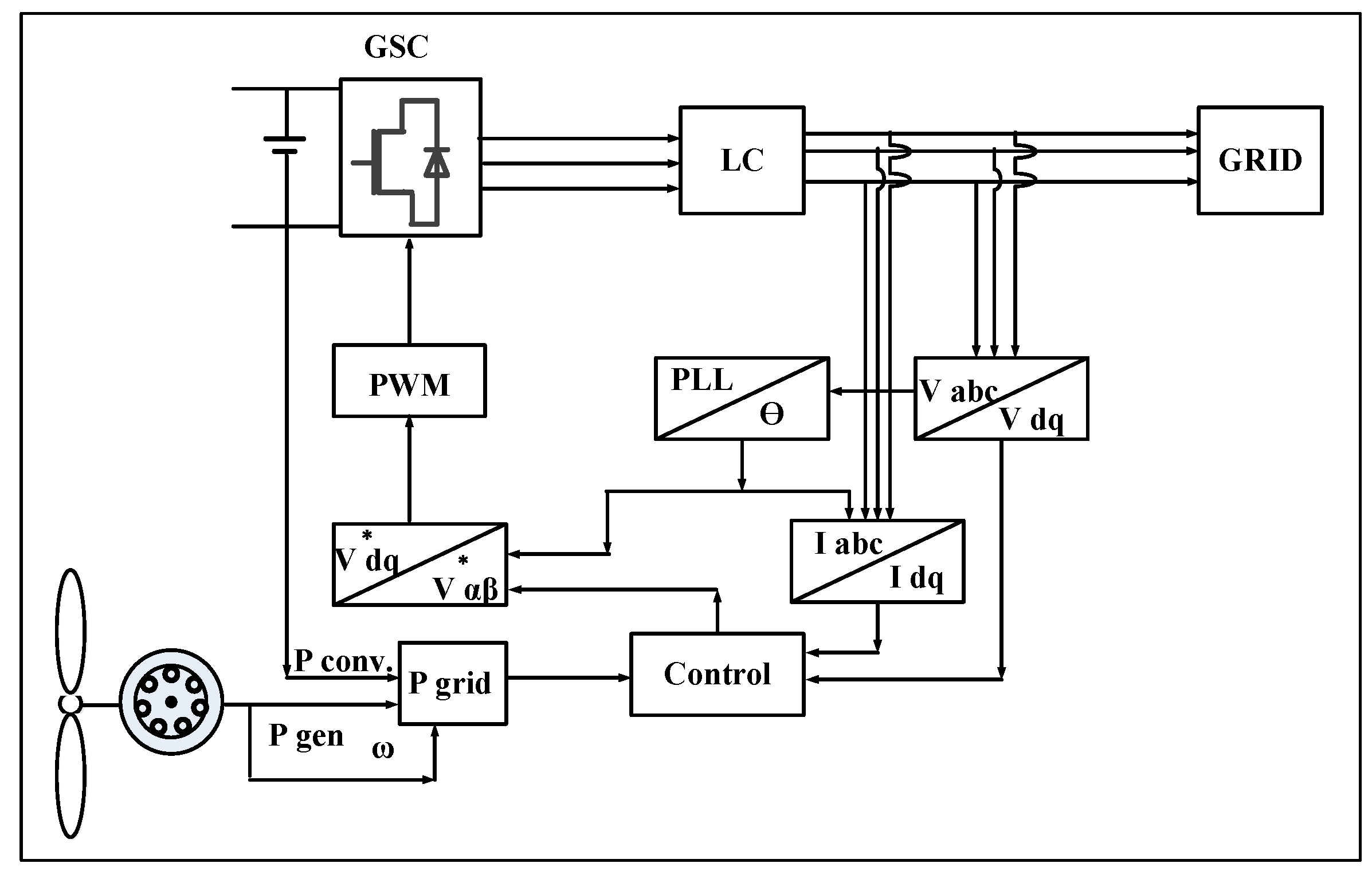
In Figure 1, a conventional controller is shown, where MPPT is achieved with the help of MSC. However, in this paper, MSC is utilized for the suppression of DC-link over-voltage. The proposed control system is illustrated in Figure 2. In Figure 3, the GSC is shown performing the maximum power point tracking as well as compensating the unbalanced grid voltages.
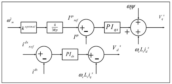
Figure 1.
Conventional machine side control.

Figure 2.
Proposed machine side control.
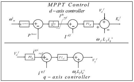
Figure 3.
Proposed grid side control.
3. Background Information
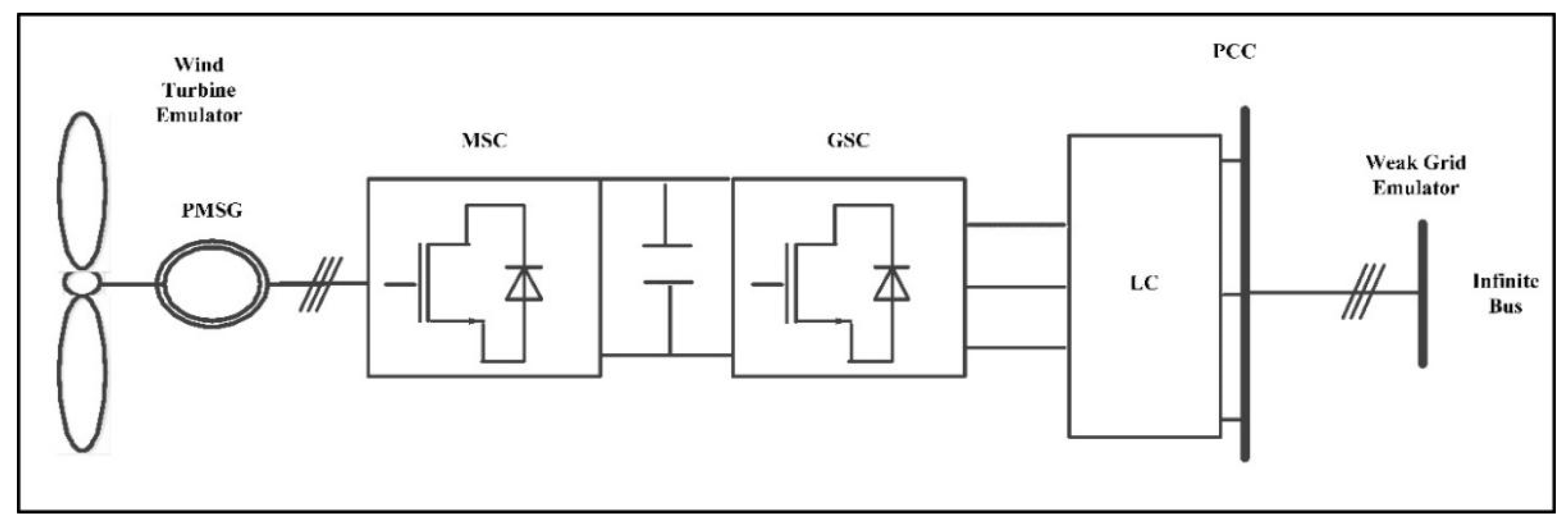
In Figure 4, a PMSG-based WECS is shown. The configuration has three major parts:

Figure 4.
Proposed PMSG-based WECS configuration.
- Permanent magnet synchronous generator;
- Back to back converters; and
- AC grid.
3.1. Permanent Magnet Synchronous Generator
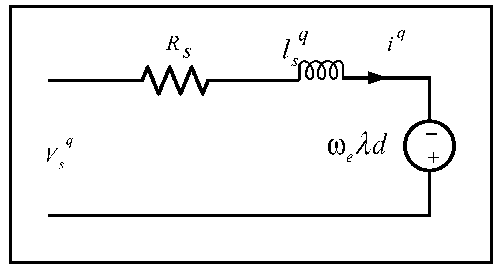
The mathematical modeling of voltages of a surface-mounted PMSG is considered in the synchronous d-q reference frame. In Figure 5 and Figure 6, the d-axis and q-axis equivalent circuits are shown, respectively [17,18,19]. The expressions defining the cross-coupling effect in d-q axis voltages are expressed as (1) and (2):
where the PMSG stator winding resistance is denoted with Rs and inductance is donated with Ls. ,,, and are the d-q components of the stator direct and quadrature axis voltages and currents, respectively. The magnetic flux is donated with a symbol and, represents the electrical angular speed.

Figure 5.
d axis PMSG mathematical model.
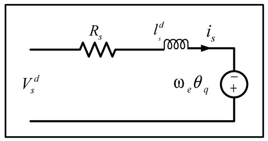
Figure 6.
q axis PMSG mathematical model.
3.2. Back to Back Converters
In Figure 4, a block diagram of the deployed scheme is shown, where GSC (grid side converter) and MSC (machine side converter) are integrated to control the power flow within the system.
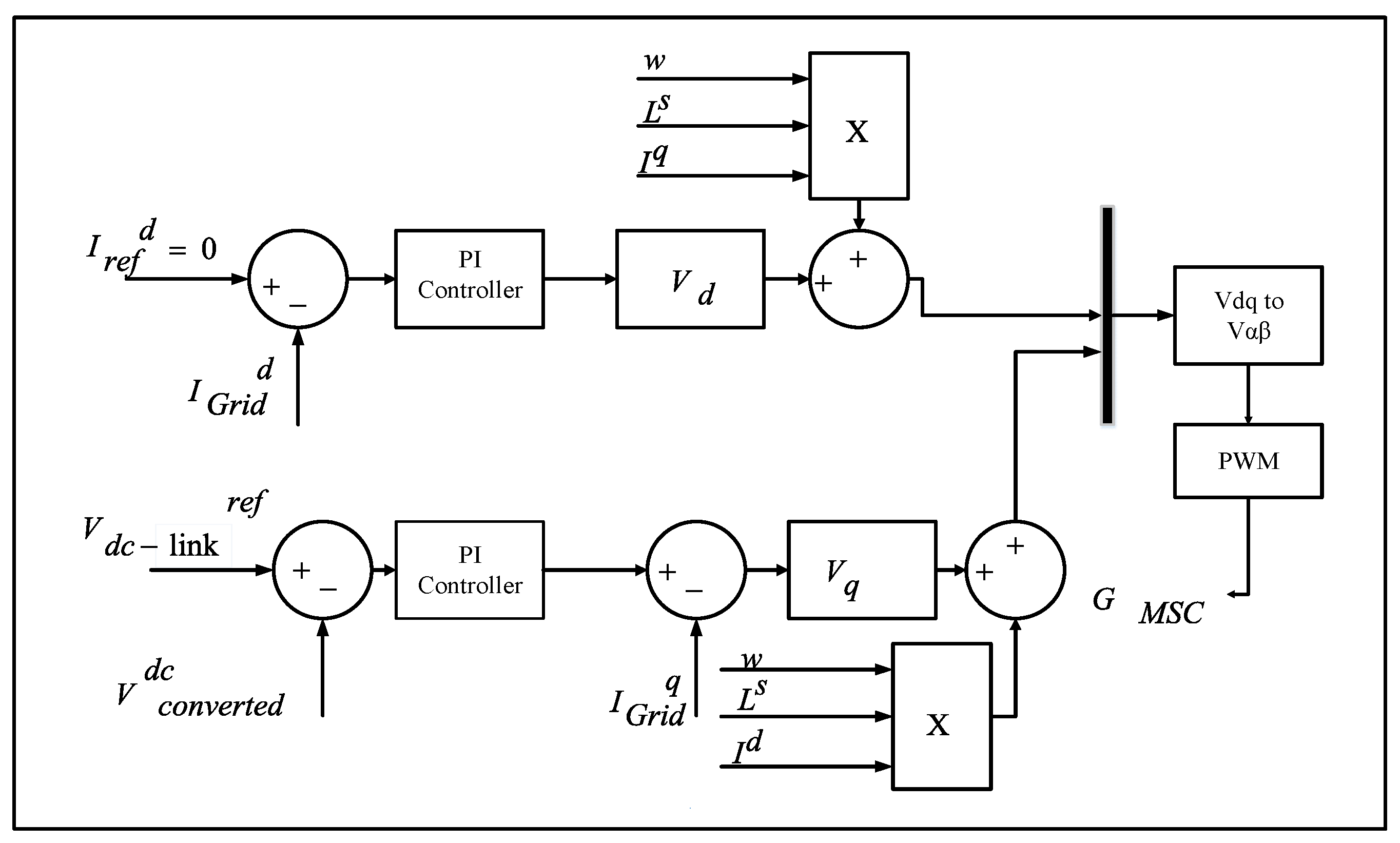
3.3. Grid Side Converter (GSC)
In the proposed control topology, wind power regulation is achieved with the help of GSC. The injection of reactive current during the asymmetrical fault is also provided by the GSC according to grid side control as shown in Figure 3. A comprehensive block diagram of the GSC control is depicted in Figure 7. In this research paper, a dual vector current control strategy for positive and negative sequences is used to eradicate second-order component oscillations of the AC grid active power. Two components P2s and P2c are set to zero for the elimination of second-order component fluctuation of AC grid active power. The negative and positive d and q axis components can be identified by solving the matrix shown in (3) [4]. During grid faults, the grid side control will regulate the voltage by injecting reactive power:
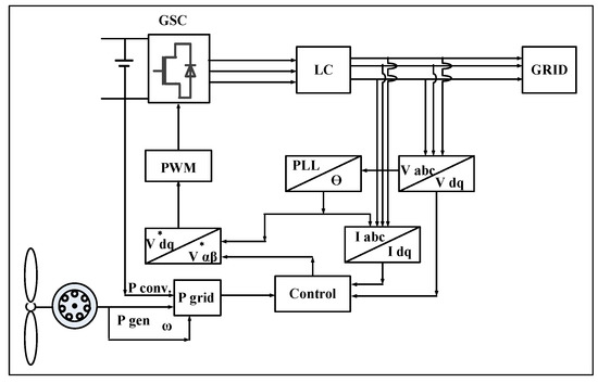
Figure 7.
Grid side control block diagram.
The extraction of the maximum generated power from wind is achieved by active-power reference . The reactive-power reference is provided according to the grid code requirement. The expression (4) gives the active power reference as:
where .
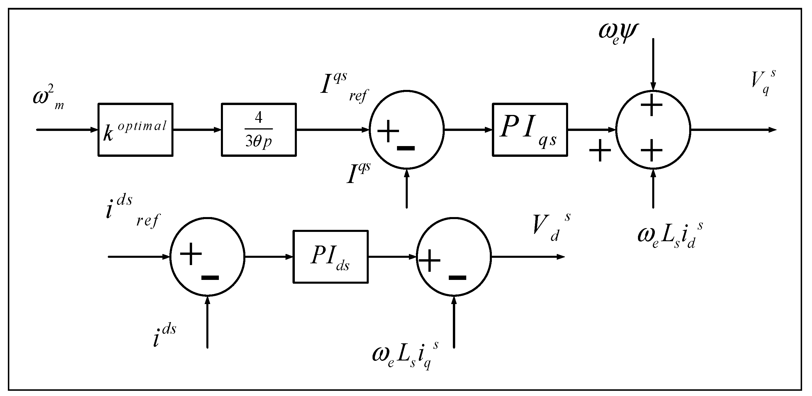
3.4. Machine Side Converter (MSC)
In the literature, the quadrature axis current (Iq) is used to obtain/extract maximum power using WECS to smoothen the power flow [13]. The proposed MSC control in this research paper has two control loops, as shown in Figure 2 [20]. In the discussed technique, actual DC-link voltage is compared with reference DC-link voltage. The comparative result difference is fed to a PI-controller to obtain the quadrature axis reference current (). The complete MSC grid control is depicted in Figure 8. The DC-link voltage is controlled in such a way that the DC-link voltage stays constant during the unbalanced condition. To avoid demagnetizing permanent magnets in PMSG and minimizing the stator winding losses, the direct-axis current (Id) is set to zero.
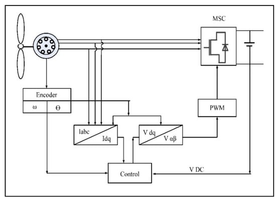
Figure 8.
Machine side control block diagram.
4. Proposed Power (Active) Limiter
The currents of each phase Ia, Ib, and Ic are considered lesser than Imax, which is the rated current. The injection of reactive current during unbalanced conditions is achieved with the help of the technique mentioned in Figure 2. The extraction of positive and negative sequence direct axis and quadrature axis currents is done with the help of (5)–(8) [4,19]:
where and are:
where δ and K are:
whereas the values of positive and negative sequences direct/quadrature axis currents and voltages are:
5. Simulation Results
To demonstrate the capability of the proposed technique, an asymmetrical fault was introduced in the WECS during the period of 1.2 to 1.4 s using the Matlab Simulink platform.
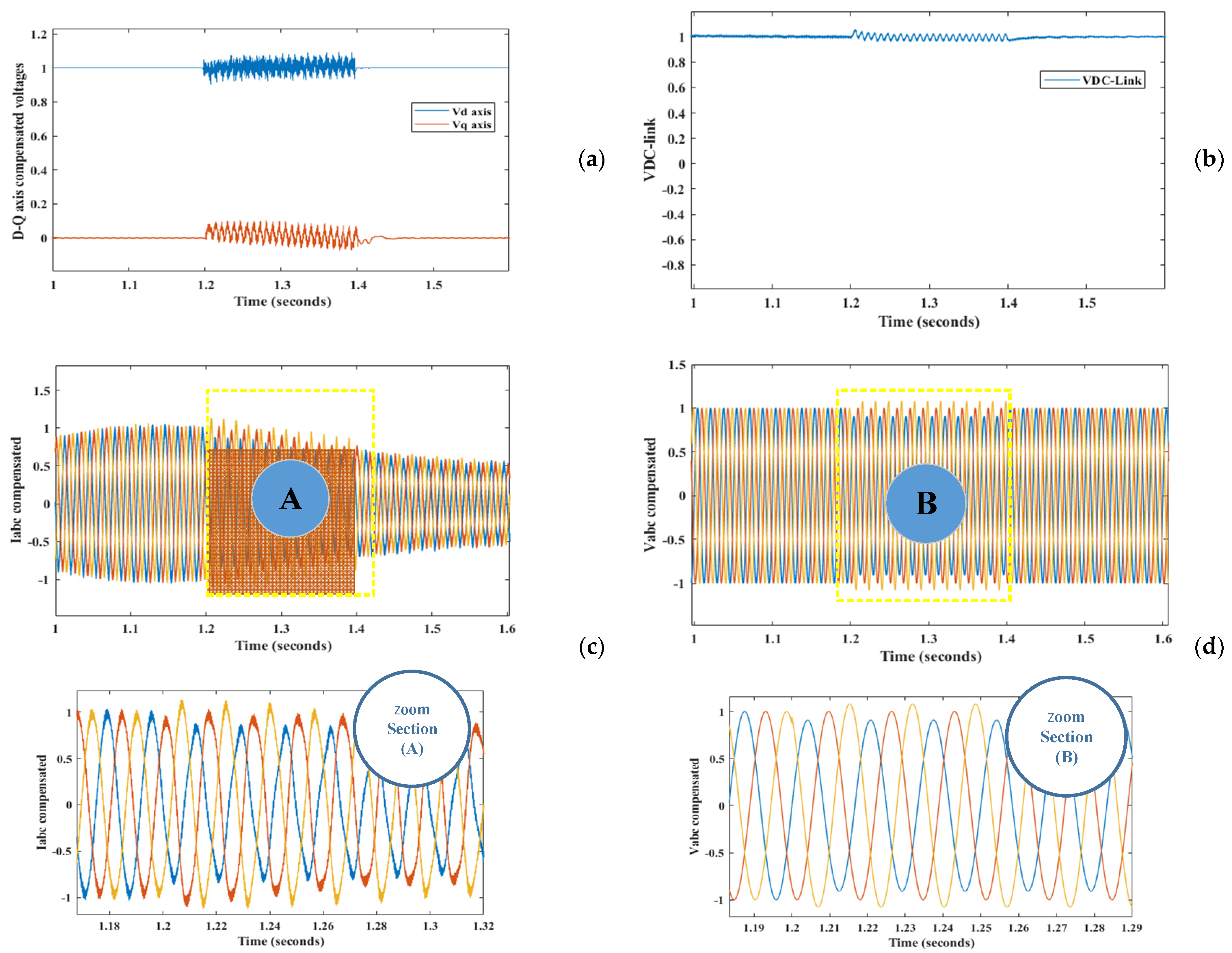
First of all, the results were extracted by implementing the technique from [13], where a crowbar was utilized to dissipate surplus power for suppression of the DC-link voltage overshoot. The Matlab-based simulation results were achieved, where the compensated d-q voltages are shown in Figure 9a and the regulated DC-link voltage is displayed in Figure 9b.
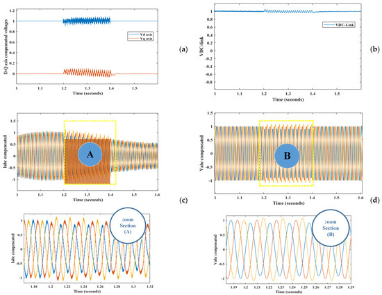
Figure 9.
Simulated results of the conventional technique using the crowbar as the DC-link voltage compensator, (a) compensated dq voltages, (b) regulated DC Link voltage, (c) grid currents, and (d) compensated grid voltages.
The grid current is presented in Figure 9c, where the current is decreasing during the fault period and has a long settling time. Using the technique discussed in [13], the system is fairly balancing the grid voltages, which can be observed in Figure 9d.
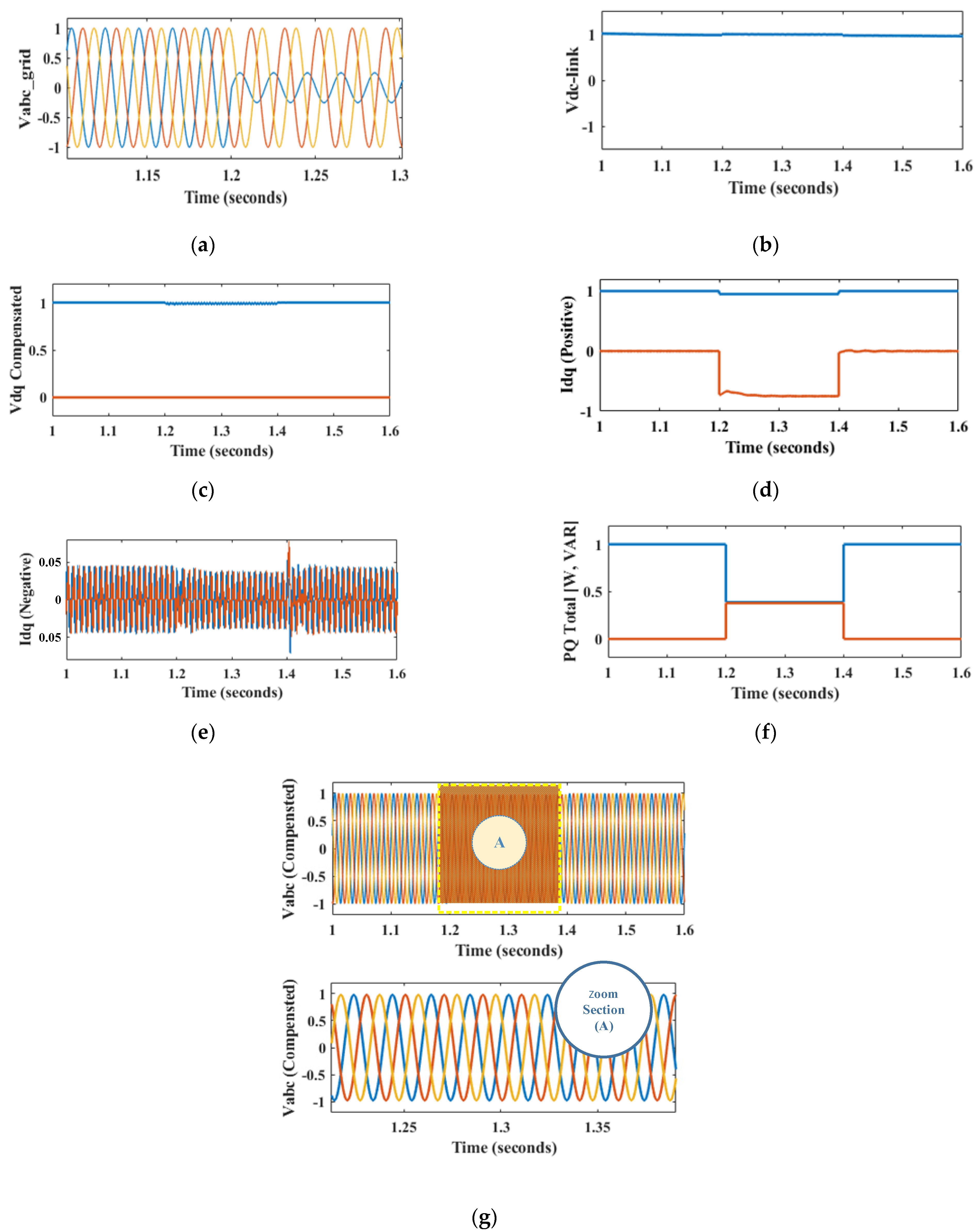
Now, for the proposed technique, the simulation-based results are displayed in Figure 10. The modified control strategy was utilized to regulate the DC-link voltage. It can be seen from the comparison of Figure 9b and Figure 10c that the DC-link voltages are more stable by implementing the proposed control with the aid of MSC, i.e., without using the additional hardware for dissipating the extra power. In Figure 10b, compensated grid dq voltages are shown.

Figure 10.
Simulated results of the proposed technique: (a) asymmetric grid voltage, (b) regulated DC-link voltage, (c) positive sequence voltages, (d) positive sequence currents, (e) negative sequence currents, (f) active and reactive powers during fault compensation, and (g) compensated three phase grid voltages.
Direct and quadrature axis positive and negative axis currents are observed in Figure 10d,e respectively. It is observed that during unbalanced conditions with the support of reactive current components, the active component is being regulated to balance the output supply as mathematically described in (13)–(16). Active/reactive power during unbalanced conditions is observed in Figure 10f.
6. Experiments and Results
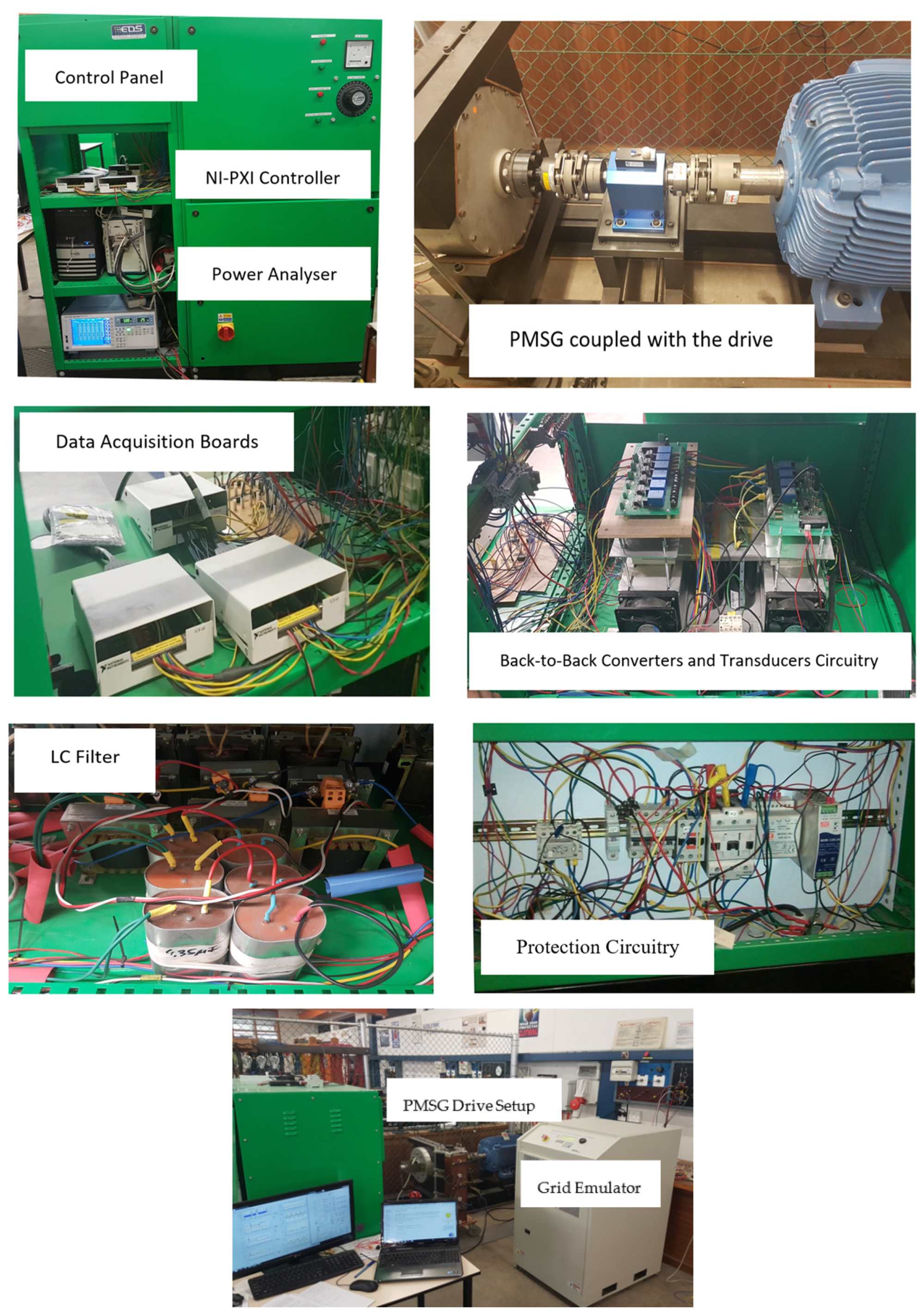
In Figure 11, the experimental lab setup is shown, where the control panel includes the FPGA-based real time controller, back-to-back converters, filter, and protection circuitry. The complete rig with a grid emulator and a variable speed prime-mover (being used as a wind turbine emulator) is also depicted here.

Figure 11.
Experimental setup: control panel, grid emulator, PMSG, and its drive.
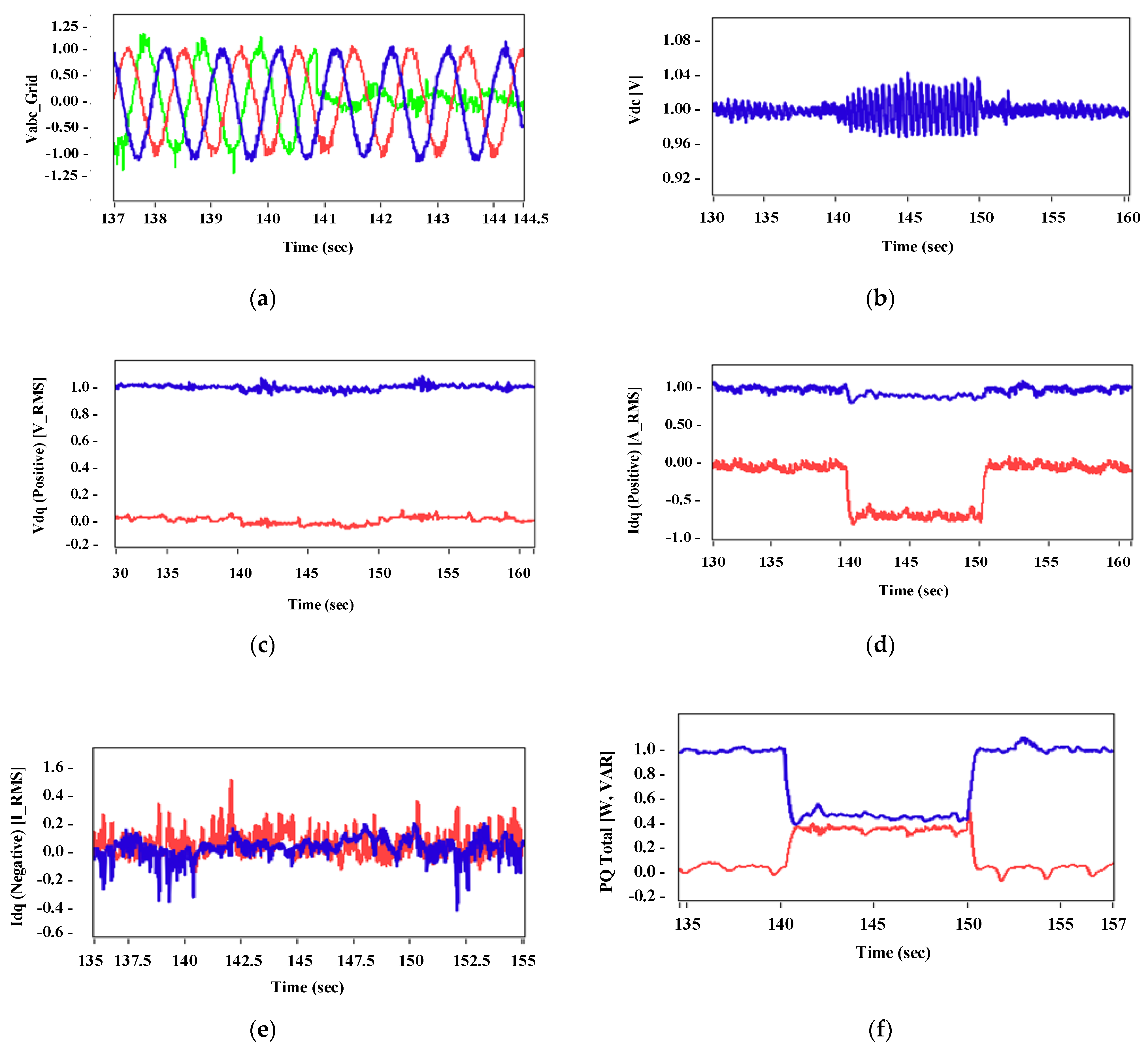
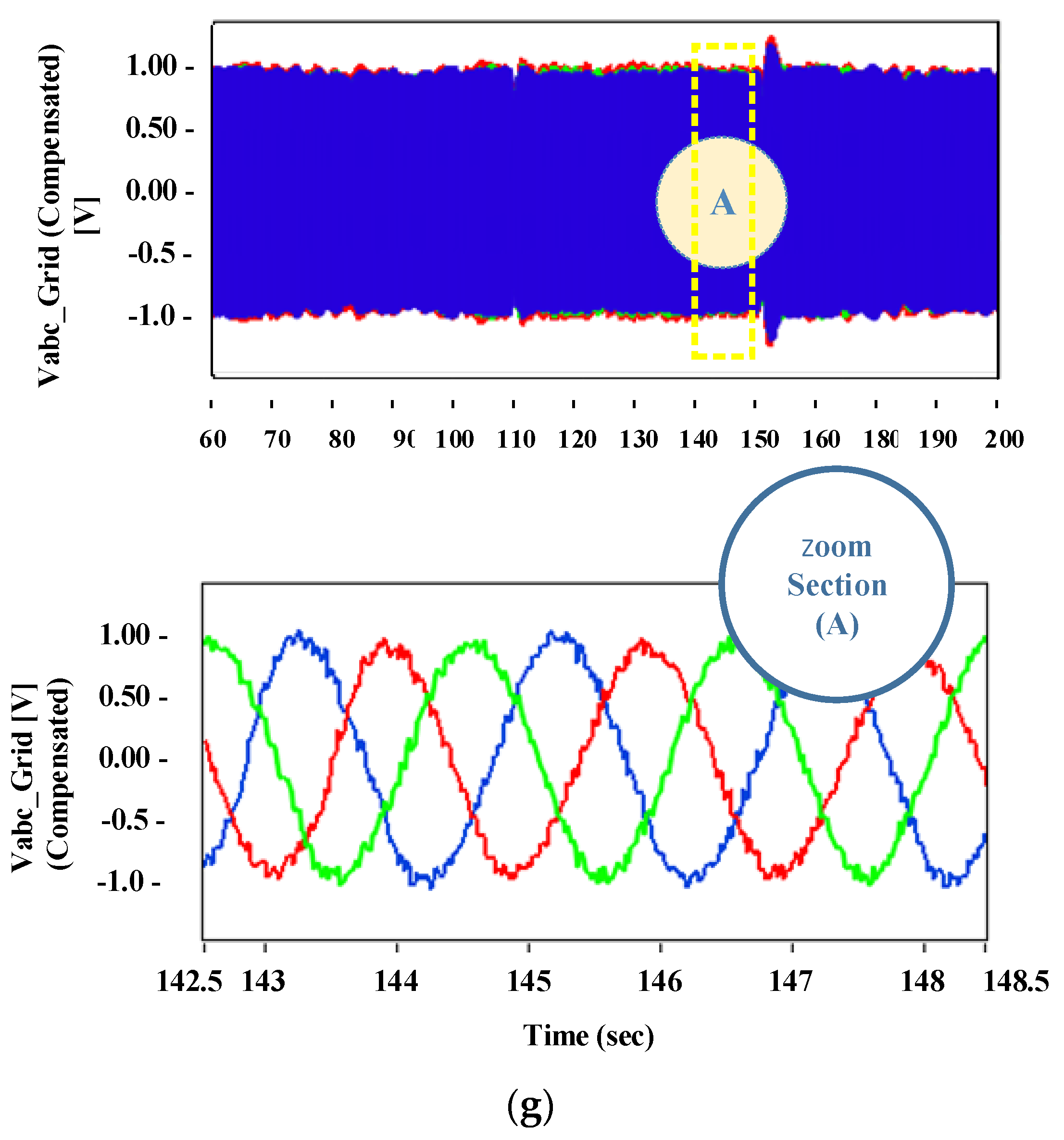
The hardware results with the implementation of the proposed technique are shown in Figure 12. These results were acquired by introducing an asymmetrical fault (single line to ground) with the help of a grid emulator for 10 s (140 to 150 s). The direct and quadrature axis positive and negative sequence currents are illustrated in Figure 12d,e respectively. The compensated grid three-phase voltages are also shown in Figure 12g.


Figure 12.
Hardware results of the proposed technique: (a) asymmetric grid voltage, (b) regulated DC-link voltage, (c) positive sequence voltages, (d) positive sequence currents, (e) negative sequence currents, (f) active and reactive powers during fault compensation, and (g) compensated three-phase grid voltages.
There are some variations, but a slight difference is observed in both Idq+ waveforms in Figure 12d and Figure 10d during the asymmetrical fault whereas balanced output three-phase voltages can be observed in Figure 12g, which is similar to the result achieved in Figure 10h.
The results were evaluated based on the simulation and hardware tests. In Figure 9, the simulation results were acquired for the conventional technique presented in [13]. The results were observed while introducing a single line to ground fault (asymmetrical fault) on a weak AC grid for 500 ms. During this unbalanced situation, an overshoot was observed in the DC-link voltage, which was suppressed with the help of a crowbar. It can be seen during the fault period that the per-unit current drops to 0.6 pu and takes more time to reach its nominal value. Although this technique is commonly used in WECS, it gives poor results during asymmetrical faults.
On the other hand, in Figure 10, simulation results were obtained by implementing the proposed technique. A similar fault was introduced in a weak AC grid and suppression of DC-link overshoot was achieved in Figure 10b with the help of MSC dual vector control. With this control technique, the requirement of any additional devices can be avoided to dissipate additional power. The compensated dq voltages are seen in Figure 10c, which are comparatively better than the conventional technique. The direct axis voltage is compensated to 0.9 pu. Moreover, the Idq+ and Idq- values are observed to be within safety limits. To experimentally validate the proposed technique, a hardware-based setup was deployed and similar results are shown in Figure 12.
7. Conclusions
In this research, a new technique was implemented to enrich the competence of low voltage ride through for a PMSG-based WECS integrated into a weak AC grid. The majority of the control techniques discussed in the literature used the conventional way of controlling the DC-link voltage with the GSC and MPPT with the MSC.
There are also many challenges related to these conventional techniques. However, by swapping the control functions of the converters, DC link over-voltages can be regulated by the MSC and the GSC can assist with the balancing of the power supply to a weak AC grid.
The three major contributions of this paper are: DC-link overshoot was regulated without any additional hardware and active/reactive power limitations were implemented during grid faults. During the DC-link regulation, grid current magnitudes were also kept within the safety limits.
8. Future Work
In this paper, the wind speed was considered to be constant. In the future, the proposed control technique could also be applied to nonlinear wind curves. The same method could also be applied by having information of weak AC grid impedances, which will allow the currents to be injected with certain angles for increased efficiency.
Author Contributions
Conceptualization, A.K. and H.A.; methodology, A.K.; software, H.A. and S.M.A.; validation, A.K., M.M.G. and S.M.; formal analysis, A.K. and H.A.; investigation, A.K. and H.A.; resources, S.M.A. and S.M.; data curation, H.A. and M.M.G.; writing—original draft preparation, A.K. and H.A.; writing—review and editing, S.M.A. and M.M.G.; visualization, A.K. and S.M.; supervision, A.K.; project administration, S.M.A. and S.M.; funding acquisition, S.M.A. and H.A. All authors have read and agreed to the published version of the manuscript.
Funding
This research received no external funding.
Institutional Review Board Statement
Not applicable.
Informed Consent Statement
Not applicable.
Data Availability Statement
Not applicable.
Conflicts of Interest
The authors declare no conflict of interest.
Nomenclature
| PMSG | Permanent magnet synchronous generator |
| LVRT | Low voltage ride through |
| WPP | Wind power plant |
| STATCOM | Static capacitor |
| ESS | Energy storage system |
| SDBR | Series dynamic breaking resistor |
| dq | Direct and quadrature axis |
| Direct axis stator voltage | |
| Quadrature axis stator voltage | |
| Stator resistance | |
| Direct axis stator current | |
| Quadrature axis stator current | |
| Magnetic flux | |
| Electrical angular speed | |
| Stator inductance | |
| Direct axis positive sequence current | |
| Direct axis negative sequence current | |
| Quadrature axis positive sequence current | |
| Quadrature axis negative sequence current | |
| Active power reference | |
| Reactive power reference | |
| Quadrature axis positive sequence voltage | |
| Quadrature axis negative sequence voltage | |
| Direct axis positive sequence voltage | |
| Direct axis negative sequence voltage | |
| Direct and quadrature axis reference current | |
| K | Reactive power reference |
| δ | Current ratio |
| Quadrature axis stator reference current | |
| Direct axis stator reference current |
References
- Khooharo, M.A.; Ali, M.; Rana, I.; Memon, A.A.; Shahani, T.A. An Alternate to the Problem of Complete load Shedding Using Smart Energy Meter. Int. J. Electr. Eng. Emerg. Technol. 2021, 4, 15–20. [Google Scholar]
- Bhutta, M.M.A.; Hayat, N.; Farooq, A.U.; Ali, Z.; Jamil, S.R.; Hussain, Z. Vertical axis wind turbine—A review of various configurations and design techniques. Renew. Sustain. Energy Rev. 2012, 16, 1926–1939. [Google Scholar] [CrossRef]
- De La Bat, J.G.; Khan, M.A.; Barendse, P. Development of a system for testing grid-connected Permanent Magnet wind generators. In Proceedings of the 2012 XXth International Conference on Electrical Machines, Marseille, France, 2–5 September 2012; pp. 2066–2071. [Google Scholar]
- Nasiri, M.; Mohammadi, R. Peak Current Limitation for Grid Side Inverter by Limited Active Power in PMSG-Based Wind Turbines During Different Grid Faults. IEEE Trans. Sustain. Energy 2017, 8, 3–12. [Google Scholar] [CrossRef]
- Dey, P.; Datta, M.; Fernando, N.; Senjyu, T. Coordinated control technique of PMSG based wind energy conversion system during repetitive grid fault. In Proceedings of the 2018 IEEE International Conference on Industrial Technology (ICIT), Lyon, France, 20–22 February 2018; pp. 915–920. [Google Scholar]
- Chen, S.-S.; Wang, L.; Lee, W.-J.; Chen, Z. Power flow control and damping enhancement of a large wind farm using a superconducting magnetic energy storage unit. IET Renew. Power Gener. 2009, 3, 23–38. [Google Scholar] [CrossRef]
- Nguyen, T.H.; Lee, D.-C. Advanced Fault Ride-Through Technique for PMSG Wind Turbine Systems Using Line-Side Converter as STATCOM. IEEE Trans. Ind. Electron. 2013, 60, 2842–2850. [Google Scholar] [CrossRef]
- Geng, H.; Liu, L.; Li, R. Synchronization and Reactive Current Support of PMSG-Based Wind Farm During Severe Grid Fault. IEEE Trans. Sustain. Energy 2018, 9, 1596–1604. [Google Scholar] [CrossRef]
- Kim, K.-H.; Jeung, Y.-C.; Lee, D.-C.; Kim, H.-G. LVRT Scheme of PMSG Wind Power Systems Based on Feedback Linearization. IEEE Trans. Power Electron. 2012, 27, 2376–2384. [Google Scholar] [CrossRef]
- Aydarous, A.; Elshahed, M.A.; Hassan, M.A.M. Short term load forecasting as a base core of smart grid integrated intelligent energy management system. In Proceedings of the 2017 International Conference on Modern Electrical and Energy Systems (MEES), Kremenchuk, Ukraine, 15–17 November 2017; pp. 192–195. [Google Scholar]
- Schmall, J.; Huang, S.-H.; Li, Y.; Billo, J.; Conto, J.; Zhang, Y. Voltage stability of large-scale wind plants integrated in weak networks: An ERCOT case study. In Proceedings of the 2015 IEEE Power & Energy Society General Meeting, Denver, CO, USA, 26–30 July 2015; pp. 1–5. [Google Scholar]
- Zhou, J.Z.; Gole, A.M. VSC transmission limitations imposed by AC system strength and AC impedance characteristics. In Proceedings of the 10th IET International Conference on AC and DC Power Transmission (ACDC 2012), Birmingham, UK, 4–5 December 2012; p. 6. [Google Scholar]
- Tande, J.O.; Di Marzio, G.; Uhlen, K. System Requirements for Wind Power Plants. 2007. Available online: https://www.sintef.no/globalassets/upload/energi/pdf/vind/tr-a6586.pdf (accessed on 6 April 2021).
- Tan, K.; Islam, S. Optimum Control Strategies in Energy Conversion of PMSG Wind Turbine System without Mechanical Sensors. IEEE Trans. Energy Convers. 2004, 19, 392–399. [Google Scholar] [CrossRef]
- Van Kuik, G.A. The lanchester–betz–joukowsky limit. Wind Energy Int. J. Prog. Appl. Wind. Power Convers. Technol. 2007, 10, 289–291. [Google Scholar] [CrossRef]
- Xing, P.; Fu, L.; Wang, G.; Wang, Y.; Zhang, Y. A compositive control method of low-voltage ride through for PMSG-based wind turbine generator system. IET Gener. Transm. Distrib. 2018, 12, 117–125. [Google Scholar] [CrossRef]
- Nasiri, M.; Milimonfared, J.; Fathi, S. Modeling, analysis and comparison of TSR and OTC methods for MPPT and power smoothing in permanent magnet synchronous generator-based wind turbines. Energy Convers. Manag. 2014, 86, 892–900. [Google Scholar] [CrossRef]
- Rani, M.A.A.; Nagamani, C.; Ilango, G.S.; Karthikeyan, A. An Effective Reference Generation Scheme for DFIG With Unbalanced Grid Voltage. IEEE Trans. Sustain. Energy 2014, 5, 1010–1018. [Google Scholar] [CrossRef]
- Sharma, H.; Islam, S.; Nayar, C. Power quality simulation of a variable speed wind generator connected to a weak grid. In Proceedings of the Ninth International Conference on Harmonics and Quality of Power. Proceedings (Cat. No. 00EX441), Orlando, FL, USA, 1–4 October 2002; Volume 3, pp. 988–993. [Google Scholar] [CrossRef]
- Strachan, N.P.W.; Jovcic, D. Stability of a Variable-Speed Permanent Magnet Wind Generator with Weak AC Grids. IEEE Trans. Power Deliv. 2010, 25, 2779–2788. [Google Scholar] [CrossRef]


Publisher’s Note: MDPI stays neutral with regard to jurisdictional claims in published maps and institutional affiliations. |
© 2021 by the authors. Licensee MDPI, Basel, Switzerland. This article is an open access article distributed under the terms and conditions of the Creative Commons Attribution (CC BY) license (https://creativecommons.org/licenses/by/4.0/).