
Intelligent Permanent Magnet Motor-Based Servo Drive System Used for Automated Tuning of Piano


Abstract
:1. Introduction
2. Piano Tuning Device and Its Servo Drive System
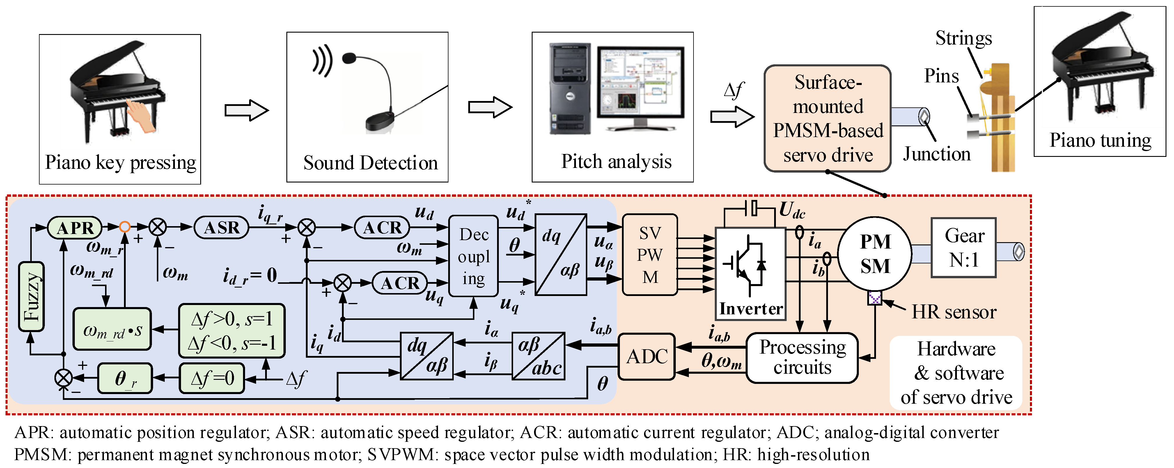
2.1. Structure and Principles of the Proposed Tuning Devices
2.2. Surface-Mounted Permanent Magnet Synchronous Motor-Based Servo Drive System
3. Proportional Integral Controller Design for Double Closed-Loop Speed-Regulation Scheme
3.1. Current-Loop Analysis
3.2. Speed-Loop Analysis
4. Fuzzy-Adaptive Proportional Integral Controller Design for Triple Closed-Loop Position-Regulation Scheme
4.1. Proposed Fuzzy Afdaptive Proportional Integral Controller
4.2. Design of Fuzzy Controller
4.2.1. Fuzzification
4.2.2. Fuzzy Control Rules
4.2.3. Membership Functions
4.2.4. Defuzzification
4.2.5. Adjustment
5. Simulation Verifications
5.1. Case 1
5.2. Case 2
5.3. Case 3
5.4. Case 4
5.5. Case 5
6. Conclusions
Author Contributions
Funding
Institutional Review Board Statement
Informed Consent Statement
Data Availability Statement
Conflicts of Interest
References
- Michon, R.; Smith, J.O.; Wright, M.; Chafe, C.; Granzow, J.; Wang, G. Mobile Music, Sensors, Physical Modeling, and Digital Fabrication: Articulating the Augmented Mobile Instrument. Appl. Sci. 2017, 7, 1311. [Google Scholar] [CrossRef] [Green Version]
- Liu, Y.; Jiang, Y.; Wu, X.; Xu, J.; Yang, Y. The Study of Piano Tuning System Based on the TMS320 Series DSP Chip. In Proceedings of the 2010 International Conference on Digital Manufacturing & Automation, Changsha, China, 18–20 December 2010; pp. 819–822. [Google Scholar]
- Davis, R.L.; Sun, Y.; Sanderson, P.L. Adaptation of a piano tuning device for the visually impaired. In Proceedings of the IEEE 31st Annual Northeast Bioengineering Conference, Hoboken, NJ, USA, 2–3 April 2005; pp. 85–86. [Google Scholar]
- Chao-Fernández, R.; Gisbert-Caudeli, V.; Vázquez-Sánchez, R. Emotional Training and Modification of Disruptive Behaviors through Computer-Game-Based Music Therapy in Secondary Education. Appl. Sci. 2020, 10, 1796. [Google Scholar] [CrossRef] [Green Version]
- Miragaia, R.; Fernández, F.; Reis, G.; Inácio, T. Evolving a Multi-Classifier System for Multi-Pitch Estimation of Piano Music and Beyond: An Application of Cartesian Genetic Programming. Appl. Sci. 2021, 11, 2902. [Google Scholar] [CrossRef]
- Shah, S.; Välimäki, V. Automatic Tuning of High Piano Tones. Appl. Sci. 2020, 10, 1983. [Google Scholar] [CrossRef] [Green Version]
- Borruto, A.; Narducci, G.; Buccitti, M. Failure Analysis of Piano Strings. Eng. Fail. Anal. 2013, 35, 164–177. [Google Scholar] [CrossRef]
- Millard, M.; Tizhoosh, H.R. Tuning Pianos Using Reinforcement Learning. Appl. Acoust. 2006, 68, 576–593. [Google Scholar] [CrossRef]
- Sica, A.M. The Development of the Keyboard through the Grand Piano and Its Effect on Piano Literature. Senior Honors Thesis, Liberty University, Lynchburg, VA, USA, 2008; pp. 1–39. Available online: https://digitalcommons.liberty.edu/honors/index.11.html (accessed on 25 July 2021).
- Hingrichsen, H. Entropy-based Tuning of Musical Instruments. Rev. Bras. Ensino Fis. 2012, 34, 2031. [Google Scholar]
- Aguilar, J.R.; Salinas, R. New Trends in Sound Synthsis and Automatic Tuning of Electronic Musical Instruments. Rev. Fac. De Ing. 2003, 11, 17–23. [Google Scholar]
- Garo, M.; Joseph, T. Final Year Project Report-Automatic Piano Tuning; Faculty of Engineering and Architecture American, University of Beirut: Beirut, Lebanon, 2020; pp. 1–73. [Google Scholar]
- Tuovinen, J.; Hu, J.; Välimäki, V. Toward Automatic Tuning of the Piano. In Proceedings of the 16th Sound & Music Computing Conference SMC 2019, Malaga, Spain, 28–31 May 2019; pp. 143–150. [Google Scholar]
- Tuovinen, J. Signal Processing in a Semi-Automatic Piano Tuning System; School of Electrical Engineering, Aalto University: Espoo, Finland, 2019; pp. 1–58. [Google Scholar]
- Wang, S.; Lee, A. A 12-Step Sensorless Drive for Brushless DC Motors Based on Back-EMF Differences. IEEE Trans. Energy Convers. 2015, 30, 646–654. [Google Scholar] [CrossRef]
- Kolano, K.; Drzymała, B.; Gęca, J. Sinusoidal Control of a Brushless DC Motor with Misalignment of Hall Sensors. Energies 2021, 14, 3845. [Google Scholar] [CrossRef]
- Kwak, B.; Um, J.; Seok, J. Direct Active and Reactive Power Control of Three-Phase Inverter for AC Motor Drives With Small DC-Link Capacitors Fed by Single-Phase Diode Rectifier. IEEE Trans. Ind. Appl. 2019, 55, 3842–3850. [Google Scholar] [CrossRef]
- Gamazo-Real, J.C.; Vázquez-Sánchez, E.; Gómez-Gil, J. Position and Speed Control of Brushless DC Motors Using Sensorless Techniques and Application Trends. Sensors 2010, 10, 6901–6947. [Google Scholar] [CrossRef] [PubMed] [Green Version]
- Gong, C.; Hu, Y.; Gao, J.; Wang, Y.; Yan, L. An Improved Delay-Suppressed Sliding-Mode Observer for Sensorless Vector-Controlled PMSM. IEEE Trans. Ind. Electron. 2020, 67, 5913–5923. [Google Scholar] [CrossRef]
- Xia, X.; Zhang, B.; Li, X. High Precision Low-Speed Control for Permanent Magnet Synchronous Motor. Sensors 2020, 20, 1526. [Google Scholar] [CrossRef] [PubMed] [Green Version]
- Wang, Z.; Chen, J.; Cheng, M.; Chau, K.T. Field-oriented control and direct torque control for paralleled VSIs fed PMSM drives with variable switching frequencies. IEEE Trans. Power Electron. 2016, 31, 2417–2428. [Google Scholar] [CrossRef]
- Ge, L.; Ralev, I.; Klein-Hessling, A.; Song, S.; De Doncker, R.W. A Simple Reluctance Calibration Strategy to Obtain the Flux-Linkage Characteristics of Switched Reluctance Machines. IEEE Trans. Power Electron. 2020, 35, 2787–2798. [Google Scholar] [CrossRef]
- Urbanski, K.; Janiszewski, D. Sensorless Control of the Permanent Magnet Synchronous Motor. Sensors 2019, 19, 3546. [Google Scholar] [CrossRef] [Green Version]
- Gong, C.; Hu, Y.; Chen, G.; Wen, H.; Wang, Z.; Ni, K. A DC-Bus Capacitor Discharge Strategy for PMSM Drive System with Large Inertia and Small System Safe Current in EVs. IEEE Trans. Ind. Electron. 2019, 15, 4709–4718. [Google Scholar] [CrossRef]
- Han, Y.; Wu, X.; He, G.; Hu, Y.; Ni, K. Nonlinear Magnetic Field Vector Control With Dynamic-Variant Parameters for High-Power Electrically Excited Synchronous Motor. IEEE Trans. Power Electron. 2020, 35, 11053–11063. [Google Scholar] [CrossRef]
- Gao, J.; Gong, C.; Li, W.; Liu, J. Novel Compensation Strategy for Calculation Delay of Finite Control Set Model Predictive Current Control in PMSM. IEEE Trans. Ind. Electron. 2020, 67, 5816–5819. [Google Scholar] [CrossRef]
- Abosh, A.H.; Zhu, Z.; Ren, Y. Cascaded Direct Torque Control of Unbalanced PMSM with Low Torque and Flux Ripples. IEEE Trans. Power Electron. 2018, 33, 1740–1749. [Google Scholar] [CrossRef]
- Zhang, X.; Chen, Y.; Mollet, Y.; Yang, J.; Gyselinck, J. An Accurate Discrete Current Controller for High-Speed PMSMs/Gs in Flywheel Applications. Energies 2020, 13, 1458. [Google Scholar] [CrossRef] [Green Version]
- Gong, C.; Hu, Y.; Ni, K.; Liu, J.; Gao, J. SM Load Torque Observer-Based FCS-MPDSC With Single Prediction Horizon for High Dynamics of Surface-Mounted PMSM. IEEE Trans. Power Electron. 2020, 35, 20–24. [Google Scholar] [CrossRef]
- Tumbek, M.; Kesler, S. Design and Implementation of a Low Power Outer-Rotor Line-Start Permanent-Magnet Synchronous Motor for Ultra-Light Electric Vehicles. Energies 2019, 12, 3174. [Google Scholar] [CrossRef] [Green Version]
- Useche, J.; Hurtado, R. Melodies as Maximally Disordered Systems under Macroscopic Constraints with Musical Meaning. Entropy 2019, 21, 532. [Google Scholar] [CrossRef] [PubMed] [Green Version]
- Thompson, M. Note Detection and Multiple Fundamental Frequency Estimation in Piano Recordings. Master’s Thesis, Graduate Faculty, Auburn University, Auburn, AL, USA, 2015; pp. 1–70. Available online: http://etd.auburn.edu/handle/10415/4939?show=full (accessed on 25 July 2021).
- Maggio, F.; Biral, F.; Lio, M.D. How Gearbox Ratios Influence Lap Time and Driving Style. An Analysis Based on Time-Optimal Maneuvers. SAE Tech. Papers 2003, 32, 1–9. [Google Scholar]
- Han, Y.; Gong, C.; Yan, L.; Wen, H.; Wang, Y.; Shen, K. Multiobjective Finite Control Set Model Predictive Control Using Novel Delay Compensation Technique for PMSM. IEEE Transac. Power Electron. 2020, 35, 11193–11204. [Google Scholar] [CrossRef]
- Alkorta, P.; Barambones, O.; Cortajarena, J.A.; Martija, I.; Maseda, F.J. Effective Position Control for a Three-Phase Motor. Electronics 2020, 9, 241. [Google Scholar] [CrossRef] [Green Version]
- Halder, S.; Srivastava, S.P.; Agarwal, P. Lux weakening control algorithm with MTPA control of PMSM drive. In Proceedings of the 2014 IEEE 6th India International Conference on Power Electronics (IICPE), Kurukshetra, India, 8–10 December 2014; pp. 1–5. [Google Scholar]
- Lu, J. Automatic Control Theories, 2nd ed.; Northwestern Polytechnical University Press: Xi’an, China, 2009; ISBN 978-7-5612-2637-7. [Google Scholar]
- Chuan, H.; Fazeli, S.M.; Wu, Z.; Burke, R. Mitigating the Torque Ripple in Electric Traction Using Proportional Integral Resonant Controller. IEEE Trans. Veh. Technol. 2020, 69, 10820–10831. [Google Scholar] [CrossRef]
- Zhang, Z.; Wei, H.; Zhang, W.; Jiang, J. Ripple Attenuation for Induction Motor Finite Control Set Model Predictive Torque Control Using Novel Fuzzy Adaptive Techniques. Processes 2021, 9, 710. [Google Scholar] [CrossRef]
- Jerković Štil, V.; Varga, T.; Benšić, T.; Barukčić, M. A Survey of Fuzzy Algorithms Used in Multi-Motor Systems Control. Electronics 2020, 9, 1788. [Google Scholar] [CrossRef]


| Tuning Methods | Features | |
|---|---|---|
| Advantages | Disadvantages | |
| Manual tuning |
|
|
| Semi-automated tuning |
|
|
| Automated tuning |
|
|
| s3 | Ls·Ts | Rs + kc_p |
| s2 | RsTs + Ls | kc_i |
| s1 | 0 | |
| s0 | kc_i | 0 |
| Parameters | Value | Unit |
|---|---|---|
| Stator inductance Ls | 3 | mH |
| Stator resistance Rs | 0.08 | Ω |
| Number of motor pole pairs pm | 3 | - |
| Number of resolver pole pairs pr | 3 | - |
| inertia of the rotor J | 0.0003 | kg·m2 |
| Direct-current-bus voltage Udc | 48 | V |
| Rated speed ωm_rd | 2.1 | rad/s |
| s4 | a4 | a2 | a0 |
| s3 | a3 | a1 | 0 |
| s2 | a0 | 0 | |
| s1 | 0 | 0 | |
| s0 | a0 | 0 | 0 |
| In | PL | PM | PS | ZO | NS | NM | NL |
| Outp | ZO | NS | NM | NL | NM | NS | ZO |
| In | PL | PM | PS | ZO | NS | NM | NL |
| Outi | ZO | PS | PM | PL | PM | PS | ZO |
Publisher’s Note: MDPI stays neutral with regard to jurisdictional claims in published maps and institutional affiliations. |
© 2021 by the authors. Licensee MDPI, Basel, Switzerland. This article is an open access article distributed under the terms and conditions of the Creative Commons Attribution (CC BY) license (https://creativecommons.org/licenses/by/4.0/).
Share and Cite
Zhou, Y.; Wu, Z.; Wu, Y. Intelligent Permanent Magnet Motor-Based Servo Drive System Used for Automated Tuning of Piano. Energies 2021, 14, 6627. https://doi.org/10.3390/en14206627
Zhou Y, Wu Z, Wu Y. Intelligent Permanent Magnet Motor-Based Servo Drive System Used for Automated Tuning of Piano. Energies. 2021; 14(20):6627. https://doi.org/10.3390/en14206627
Chicago/Turabian StyleZhou, Ying, Zuyu Wu, and Yutong Wu. 2021. "Intelligent Permanent Magnet Motor-Based Servo Drive System Used for Automated Tuning of Piano" Energies 14, no. 20: 6627. https://doi.org/10.3390/en14206627
APA StyleZhou, Y., Wu, Z., & Wu, Y. (2021). Intelligent Permanent Magnet Motor-Based Servo Drive System Used for Automated Tuning of Piano. Energies, 14(20), 6627. https://doi.org/10.3390/en14206627