Article

Study of the Application Characteristics of Photovoltaic-Thermoelectric Radiant Windows

1
School of Energy and Power Engineering, Nanjing University of Science and Technology, Nanjing 210094, China
2
China Unicom Consulting Design Research Institute Co., Ltd., Nanjing 210019, China
*
Author to whom correspondence should be addressed.
Energies 2021, 14(20), 6645; https://doi.org/10.3390/en14206645
Submission received: 22 September 2021 / Revised: 5 October 2021 / Accepted: 8 October 2021 / Published: 14 October 2021
(This article belongs to the Topic Electrothermal Modeling of Solar Cells and Modules)

Abstract

:
Through experiments and numerical simulation, this paper studies the related performance of a photovoltaic thermoelectric radiation cooling window structure, verifies the accuracy of the established solar thermoelectric radiation window calculation model, and analyzes the cooling performance of different parameters of thermoelectric sheet, radiation plate, and photovoltaic panel. On the basis of considering the relationship between the power generation and power consumption of the structure, the numerical calculation results show that the solar thermoelectric radiation window with non-transparent photovoltaic module (NTPV) has a total cooling capacity of 50.2 kWh, power consumption of 71.8 kWh, and power generation of 83.9 kWh from June to August. The solar thermoelectric radiation window with translucent photovoltaic module (STPV) has a total cooling capacity of 50.7 kWh, power consumption of 71.7 kWh, and power generation of 45.4 kWh from June to August. If the operation time of the thermoelectric module is limited, when the daily operation time of TEM is less than 8 h, the power generation of STPV can meet the power consumption demand of the thermoelectric radiation window from June to August.

1. Introduction

In order to achieve the national energy conservation and emission reduction grand goal of “peak carbon dioxide emissions before 2030 and achieve carbon neutrality before 2060”, renewable energy utilization and building energy conservation are the two main ways to achieve zero carbonization in the construction field [1]. Solar photovoltaic thermoelectric refrigeration technology combines photovoltaic power generation with thermoelectric refrigeration technology to improve building energy efficiency and reduce fossil energy consumption. Thus, solar photovoltaic thermoelectric refrigeration technology is expected to be used in low-energy buildings [2].
He et al. studied the application of building-integrated solar photovoltaic in low-carbon buildings, cooling rooms by a thermoelectric cooling mode powered by photovoltaic modules [3,4]. The study found that a room with a volume of 0.125 m3 could reduce the indoor temperature to 17 °C in summer with solar power, and the COP of the system could reach up to 0.45 [5]. Shen et al. proposed a new thermoelectric radiant air conditioning system (TE-RAC) which uses thermoelectric modules as radiation panels instead of traditional ones. They studied the performance parameters of the new system [6] and found that the thermoelectric sheet model TEC-12706 is highly feasible for application in this system, with a maximum COP of 1.77 when the current is 1.2 A and the cold end temperature is 20 °C [7]. Liu et al. developed a system consisting of a photovoltaic system, airflow channels, and a thermoelectric radiation cooling system [8]. They evaluated the performance of the active solar thermoelectric wall system [9], showing that the indoor temperature under the operation of this system is about 13.2 °C and the heating capacity is 111 W/m2 with a system COP of about 2.0 during a clear daytime in winter [10]. The above studies have proven the possibility of application for thermoelectric cooling in buildings. However, limited by the development of materials, this technology can only be used as an aid in engineering practice. For this reason, based on the model developed by Liu et al., the transparency of the PV module is improved and the height of the aluminum radiation panel is appropriately reduced to conduct a preliminary study for a translucent solar PV-thermoelectric radiation window, as shown in Figure 1. The non-transparent PV module (NTPV) is replaced by a semi-transparent PV (STPV) module, the height of the radiant plate is changed, and the ordinary glass is spliced with the thermoelectric structure to form a structure of equal height to the PV module, forming the PV-TEC (photovoltaic-thermoelectric) window structure discussed in this paper. The advantages of the structure include simple mechanical moving parts, a self-sufficient system energy, and partial indoor lighting effect [11].
The translucent thermoelectric radiant panel structure shields a portion of the solar radiation passing through the translucent photovoltaic module. The thermoelectric module (TEM) connected to the back of the metal aluminum plate absorbs heat from the panel. Thus, the surface temperature can be kept lower than the ambient temperature. The outdoor air passes through the air channel sandwich between the PV panel and the envelope to carry away the heat from the hot end of the TEM. Heat sinks are installed at the hot end of the TEM to increase the efficiency of heat dissipation by expanding the area for heat exchange. The thermal barrier is attached between the metal aluminum plate and the heat sink to prevent heat transfer between the two that could lead to degradation of the system’s performance. DC fans are installed above the heat sink and air channel respectively to change the airflow rate on the heat exchange surface, thus enhancing the heat dissipation performance at the hot end. The schematic structure of the whole device is shown in Figure 1.

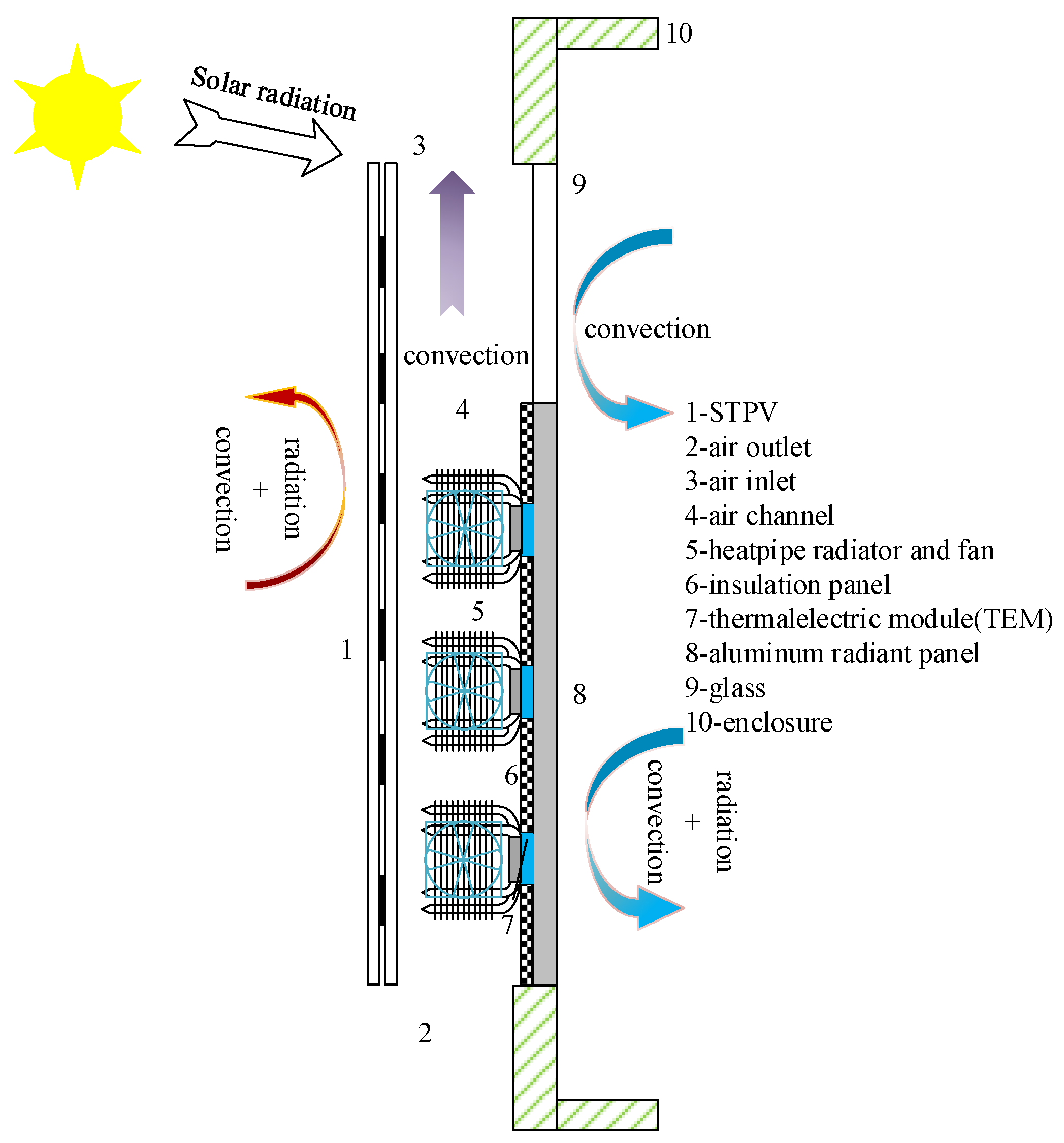
2. Mathematical Model

A heat balance model of the PV-TEC radiation window is established to calculate the temperature of the translucent PV module, transparent glass, thermoelectric module, and radiation panel. The overall translucent photovoltaic module is divided into transparent and non-transparent parts according to whether it is covered by photovoltaic cells. Among them, the opaque part is the core of the translucent photovoltaic window, which is structurally divided into five main layers, namely, outer glass layer, outer EVA layer, photovoltaic cell layer, inner EVA layer, and inner glass layer. The transparent part has only outer glass layer, EVA layer and inner glass layer. According to the heat transfer boundary, the heat transfer process of the opaque part can be divided into five parts. The heat storage in the glass layer is not considered, and the heat transfer is assumed to be a quasi-steady state process [12].
Outer glass boundary layer:
G α g l a 1 = h c , p v g l a 1 o u t ( T p v g l a 1 , o T e ) + λ g l a 1 d g l a 1 ( T p v g l a 1 , o T p v g l a 1 , i ) + ε g l a 1 h r , p v g l a 1 o u t ( T p v g l a 1 , o T e )
Outer glass layer-outer EVA layer:
G τ g l a 1 α E V A 1 + λ g l a 1 d g l a 1 ( T p v g l a 1 , o T p v g l a 1 , i ) = λ E V A 1 d E V A 1 ( T p v g l a 1 , i T p v )
Outer EVA layer-Inner EVA layer:
G τ g l a 1 τ E V A 1 α p v + λ E V A 1 d E V A 1 ( T p v g l a 1 , i T p v ) = E o u t + λ E V A 2 d E V A 2 ( T p v T p v g l a 2 , o )
Inner EVA layer-Inner glass layer:
λ E V A 2 d E V A 2 ( T p v T p v g l a 2 , o ) = λ g l a 2 d g l a 2 ( T p v g l a 2 , o T p v g l a 2 , i )
Inner glass boundary layer:
λ g l a 2 d g l a 2 ( T p v g l a 2 , o T p v g l a 2 , i ) = h a ( T p v g l a 2 , i T a i r ) + ε g l a 2 h r , p v g l a 2 i n ( T p v g l a 2 , i T r o o m )
where Tpvgla1,o, Tpvgla1,i, Tpv, Tpvgla2,o, and Tpvgla2,i denote temperature at the nodes of the outer surface of the outer glass layer, the inner surface of the outer glass layer, the PV cell, the outer surface of the inner glass layer, and the inner surface of the inner glass layer of the translucent PV module PV cell cover part; Te, Tair represent outdoor ambient temperature and air temperature in the air channel; hc,pvgla1out, ha represent convective heat transfer coefficient of the outer and inner surfaces of the translucent PV module; hr,pvgla1out, hr,pvgla2 denote radiative heat transfer coefficient of the outer and inner surfaces of the PV cell-covered part of the translucent PV module; εgla1 and εgla2 represent the surface emissivity of the glass on the outer and inner surfaces of the translucent PV module; λgla1, λEVA1, λEVA2, and λgla2 represent the thermal conductivity of the glass on the outer surface, the outer EVA laminate, the inner EVA laminate, and the inner glass of the PV cell covering part of the translucent PV module; dgla1, dEVA1, dEVA2, and dgla2 represent the thickness of the outer surface glass, outer EVA laminate, inner EVA laminate, and inner surface glass at the PV cell-covered part of the translucent PV module; G denotes the amount of solar irradiation irradiating the surface of the translucent PV module; Eout represents the amount of solar irradiation irradiating the surface of the translucent PV module power generation per unit area of the translucent PV module; αgla1, αEVA1, and αpv represent the radiation heat absorption coefficients of the outer surface glass, outer EVA laminate, and PV cell of and the translucent PV module; τgla1 and τEVA1 represent the radiation heat absorption coefficients of the outer surface glass, outer EVA laminate, and PV cell of the translucent PV module; and the radiation penetration coefficient of the glass and EVA laminate on the outer surface of the translucent PV module.
The energy balance equation in the air channel between the translucent PV module and the envelope is:
ρ D A c p d T a d t = h a A p v ( T P V T a i r ) ρ V a D c p d T a d X + Q dis
where ρ, Cp, and Va represent density, specific heat and velocity of air; D, A represent width and surface area of air channels; Tpv represent working temperature of translucent photovoltaic glass.
The translucent thermoelectric radiation plate is divided into two parts. The up-per part is a transparent glass structure, without considering the heat storage of the glass structure. The heat transfer to the room is solar radiation and convective heat transfer. The lower part is the thermoelectric radiation plate part. The surfaces of the radiation plate on the outside of the room are coated with heat insulation material. The heat dissipation on the outside of the room is the heat dissipation process of the hot side. The heat balance equation of the air channel is [13].
Q dis = ( T h T a i r ) / R z = N [ α I T h + 0.5 I 2 R K ( T h T c ) ]
The heat transfer from the cold side of the thermoelectric module is:
Q t e c = N [ α I T c 1 2 I 2 R K ( T h T c ) ]
The cooling efficiency of thermoelectric modules:
C O P = Q t e c ( P z + W )
where Th and Tc represent temperature of the hot and cold ends of the thermoelectric module; Rz represents the combined heat transfer coefficient between the hot end of the thermoelectric module and the air channel; N represents the number of thermoelectric cells in the thermoelectric module; α, R, and K represent the Seebeck coefficient, resistivity and thermal conductivity of the thermoelectric cells; I represents the current through the thermoelectric cells; Qdis and Qtec represent the heat transfer at the hot and cold sides of the thermoelectric module; Pz represents electrical energy consumed by the thermoelectric module.
The cooling of the radiant metal panels in the thermoelectric radiant windows includes convective heat transfer with the indoor air. The radiant heat transfer with the inner surfaces of the surrounding envelope and between the surfaces of other objects in the room. Referring to the formula given by ASHRAE for calculating the heat transfer from radiant panels [8], the following formula was determined.
Q panel = 2.13 | T r T p a n e l | 1.31 + ε σ ( T r 4 T p a n e l 4 )
where Tr represents indoor temperature; Tpanel represents average temperature of metal radiation panel; ε represents emissivity of metal radiation panel.

3. Numerical Calculation Process and Experimental Validation

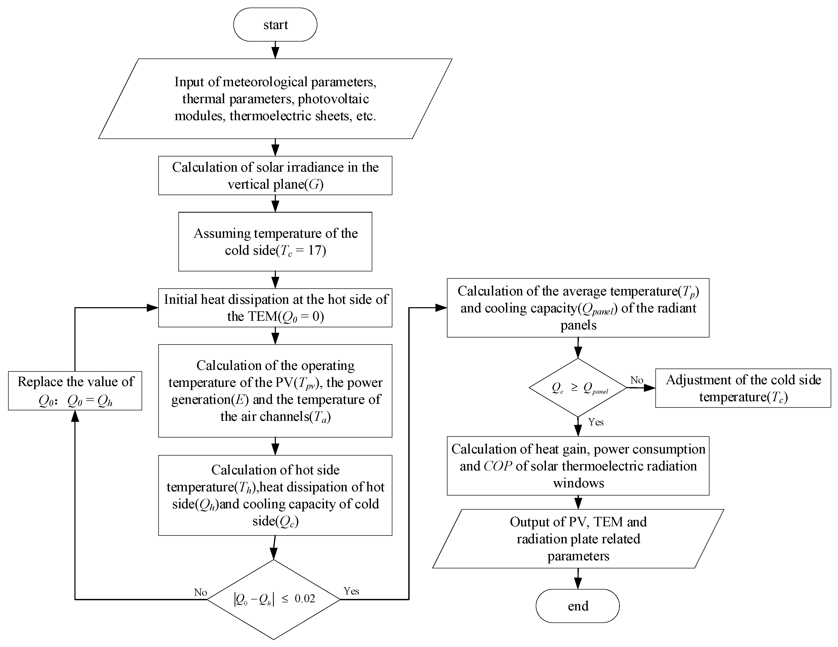
3.1. Numerical Calculation Process

In the above energy balance equation of the PV-TEC radiation window, the operating temperature of the translucent PV cell is used as a common input parameter for the generation and heat transfer of the PV glass. The air channel is used as an intermediate medium connecting the translucent PV glass and the thermoelectric radiation structure. The heat dissipation of the thermoelectric module is used as an intermediate variable to solve the coupled iterative energy balance equation of the entire PV-TEC radiation window to obtain the temperature of each part. The solar heat gain coefficient (SHGC value) and the integrated heat transfer coefficient (U value) of the PV-TEC radiation window are solved according to equations [14], and the calculated heat gain is coupled with the cooling capacity of the radiation panel, and then the temperature of the radiation panel is determined. A flow chart of the solution is shown in Figure 2.
S H G C = τ g l a s s τ E V A τ g l a s s ( 1 P V R ) τ g l a s s
U = 1 1 h o u t , c + 1 h a + 2 d 1 λ 1 + d 2 λ 2 + 1 h i n + d g l a s s λ g l a s s
where hin denotes the integrated heat transfer coefficient of the thermoelectric radiation panel on the indoor side, W/(m2·K); dglass and λglass represent the thickness and thermal conductivity of the transparent glass on the thermoelectric radiation panel (m, W/(m2·K), respectively).

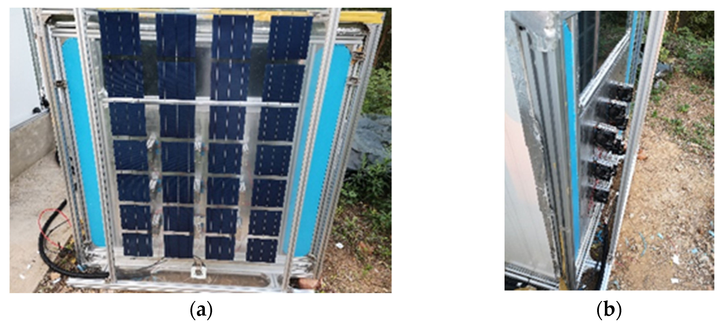
3.2. Experimental Validation

The experimental platform PV-TEC radiation window was built and a schematic diagram is shown in Figure 3. In this experiment, a semi-transparent crystalline silicon photovoltaic glass with a peak power of 150 W produced by Solar Module was selected. The photovoltaic glass has a width of 0.95 m, a height of 1.65 m, a total thickness of 8 mm, and a monocrystalline silicon cell coverage rate (PVR) of 46.3%.

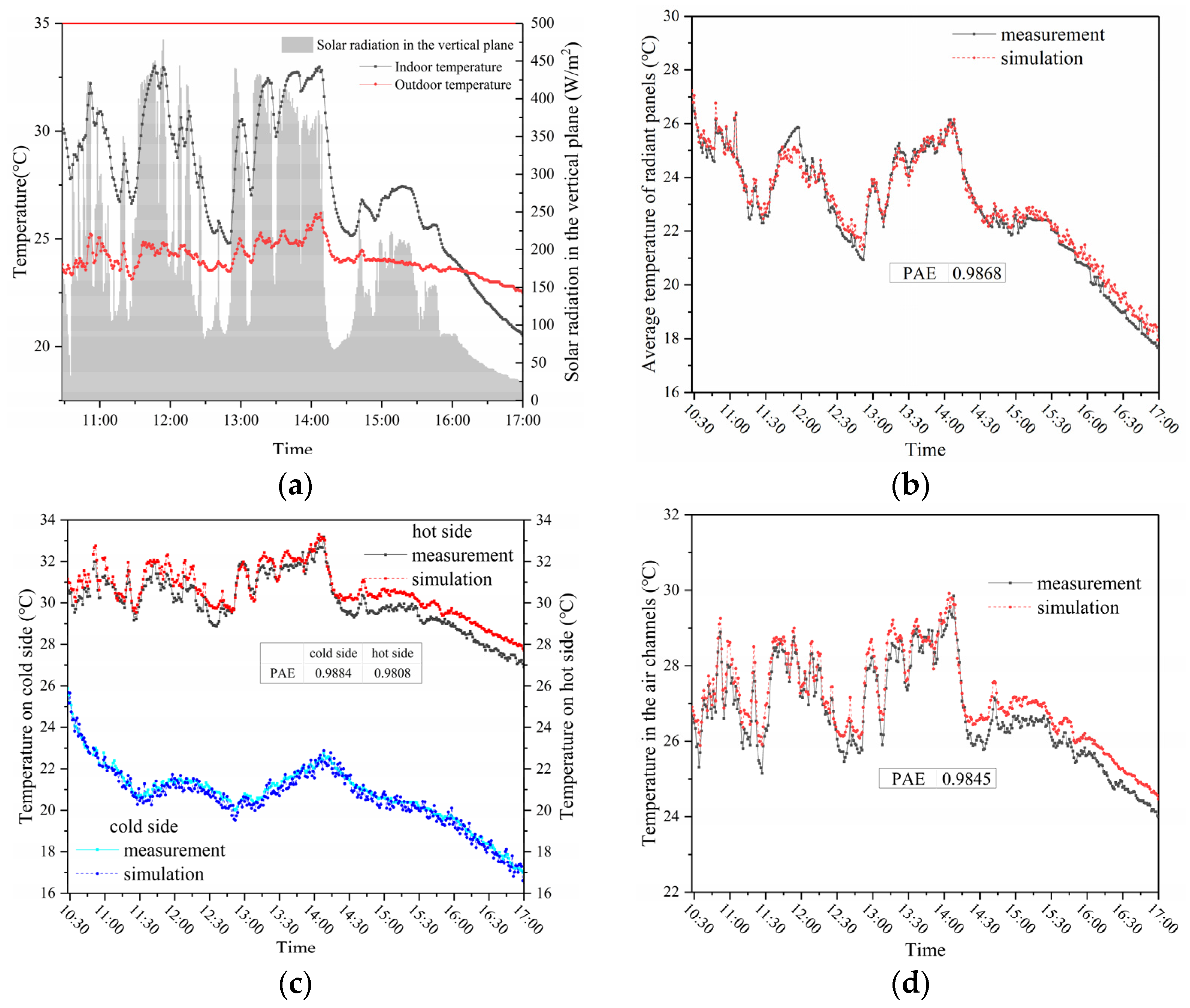
3.3. Experimental Validation and Error Analysis

Based on the above mathematical model analysis, the time period with sufficient sunlight on 13 October 2020 was selected as the continuous collection time period to validate the computational model. Figure 4a shows the measurements of indoor and outdoor dry bulb temperature and solar irradiance during this time period, and the simulation results are evaluated using the correct rate (PAE).
The experimental test method is real-time measurement and analysis, in line with the method of Daghigh’s method [15]. Figure 4b shows a comparison between the simulated and measured values of the average temperature of the radiation panel in the PV-TEC radiation window during this time period. Figure 4c shows a comparison between the simulated and measured values of the temperature of the hot and cold ends of the thermoelectric module. Figure 4d shows a comparison between the simulated and measured values of the average temperature in the air channel. From the comparison results of the three sets of temperatures, we can see that the correct rate PAE reaches 0.98 for all of them, and the errors of both the simulated and measured values are within 1 °C, thus indicating that the model has some accuracy.

4. Parameter Optimization of PV-TEC Radiation Window

4.1. Optimization of Thermoelectric Module

In the design of thermoelectric radiation panels, it is usually recommended that the maximum temperature difference between the high and low temperature regions on the surface of the radiation panel should be within 3 °C [16]. The dimensions of the thermoelectric radiant panel are optimized by the simulation of the MATLAB program. According to the design conditions for summer air conditioning, the indoor and outdoor air temperatures are set to 26 °C and 34.8 °C, respectively [17]. The surface temperature of the metal radiation plate is set to a minimum of 17 °C [18]. The input parameters used for the calculation of the temperature distribution of the thermoelectric radiation plate are shown in Table 1.
The main objective of this part is to investigate the desirable arrangement and spacing of thermoelectric modules (TEMs) to obtain a uniform temperature distribution on the surface of a thermoelectric radiant cooling panel [19].
Figure 5 shows a cloud plot of the surface temperature distribution of the thermoelectric radiation plate when the spacing between thermoelectric sheets (TECs) is varied from 0.28 m to 0.38 m at an interval of 0.2 m. From the figure, it can be seen that the simplified 1/4 TEC radiation area temperature distribution shows a fan-shaped change, TEC as a heat source in the starting position has the greatest impact, gradually away from the starting position after the surface temperature of the thermoelectric radiation plate began to gradually increase. When the spacing between TEC is 0.38 m, the average temperature difference of the surface temperature of thermoelectric radiation plate is 4.40 ± 0.30 °C (as shown in Figure 5a). As the spacing between TECs decreases at 0.02-m intervals, it can be observed that the average temperature difference of the surface temperature of the thermoelectric radiation plate also decreases gradually. When the spacing between TECs is 0.28 m, the average temperature difference of the surface temperature of the thermoelectric radiation plate is 2.86 ± 0.21 °C (as shown in Figure 5f). The results of this simulation are consistent with Han’s conclusion [20]. The recommendations of the American Society of Heating, Refrigerating and Air-Conditioning Engineers (ASHRAE) for radiant cooling panels are satisfied under this thermoelectric radiant panel sizing condition. Therefore, the ideal spacing between TECs on the proposed thermoelectric radiant panel is 0.28 m according to the above analysis. The optimized TEC spacing on the thermoelectric radiant panel is 0.28 m, which also indicates that 12 TEC cooling sheets should be placed on each square meter of radiant panel (i.e., 0.08 m2 per TEC cooling influence range).

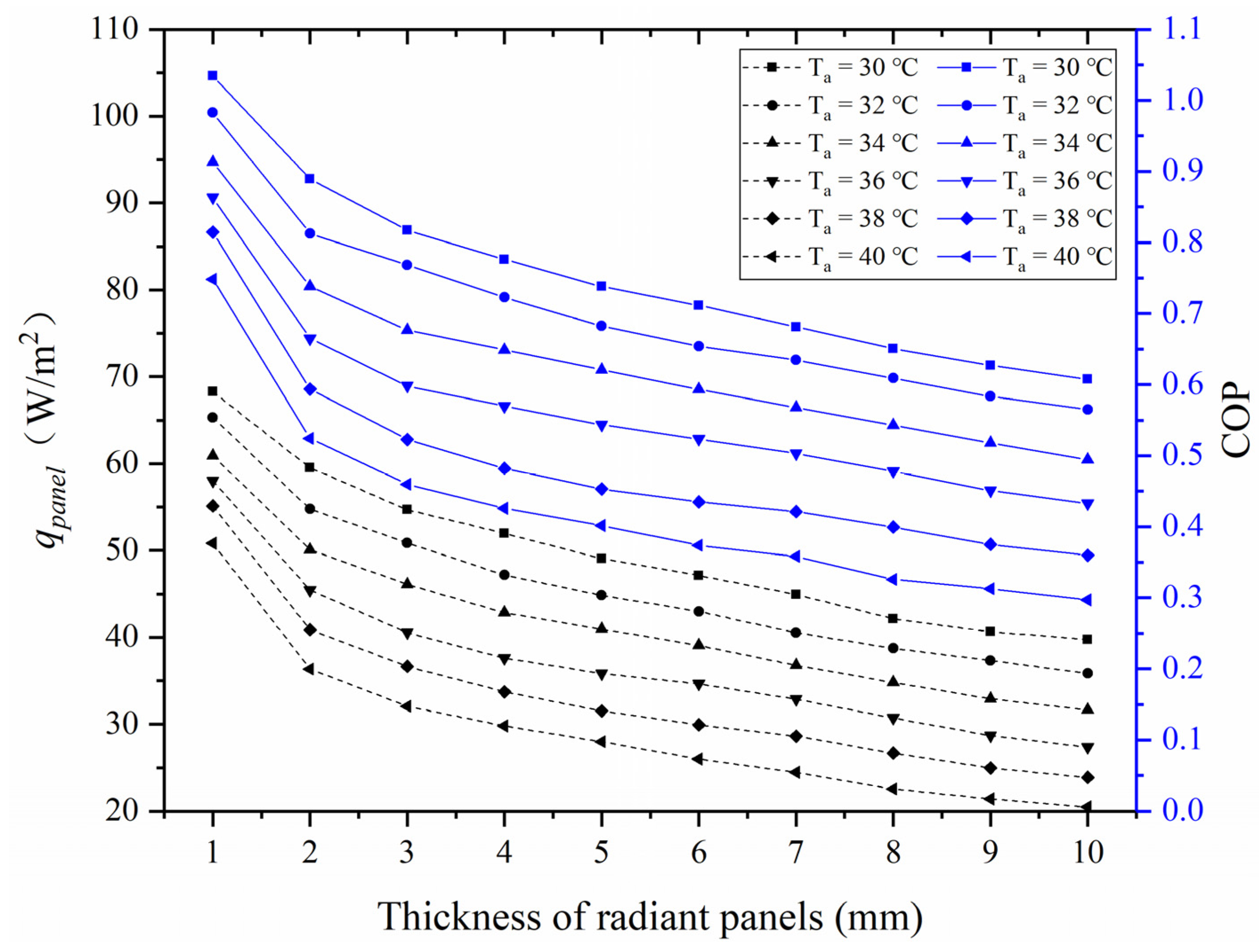
4.2. Optimization of Radiation Plate Thickness

The metallic aluminum radiant plate is the terminal device for achieving cooling in a radiant air conditioning system. The metallic aluminum radiant plate in a thermoelectric radiant plate cooling system is not different from the aluminum plate in a conventional radiant air conditioning system. In this subsection, the effect of the thickness of the metallic aluminum radiant plate on the system cooling capacity and cooling performance COP is tested by means of numerical simulations.
Figure 6 shows the cooling capacity qpanel and COP of the system under different thicknesses of the metal aluminum radiant plate when the temperature Ta in the air channel varies from 30 °C to 40 °C. From the dotted line graph of the unit cooling capacity qpanel and COP of the cooling performance in the cooling mode, we can see that the qpanel and COP are decreasing as the thickness of the metal aluminum radiant plate increases. This phenomenon indicates that the increase of the thickness of the metal aluminum radiant plate greatly impairs the cooling capacity and COP of the system. This law also conforms to the law of heat balance. Thicker radiant plates need more cooling to counteract the change of internal energy of radiant plates. The results show that the smaller the thickness of metal aluminum radiant plate as heat exchanger, the better the heat dissipation performance. At the same time, this discovery helps to improve the cooling capacity and COP of the system. From the results of numerical simulation, it can be found that as the thickness of the metallic aluminum radiant plate increases from 1 mm to 10 mm, the cooling capacity and system COP decrease by 40–60%. From the point of view of heat transfer, it is recommended to choose a thickness of the metal aluminum radiation plate in the PV-TEC radiation cooling system around 1–3 mm. However, in the actual process, the structural mechanical characteristics such as the weight-bearing of the metal radiation plate should be considered, so it is more appropriate to choose 4-mm thick metal aluminum radiation plate.

4.3. Optimization of Radiation Plate Thickness

In comparison with other scholars’ studies, the non-transparent PV modules conventionally used in photovoltaic power generation were improved by changing the original non-transparent crystalline silicon PV modules to translucent crystalline silicon PV modules for power generation, with the aim of being able to increase the light transmission in the room. However, during the implementation process, it was found that when the PV module was combined with a thermoelectric radiation panel, the size of the radiation panel was equivalent to about 60% of the PV module in order to ensure a certain cooling capacity. In this way, the area of light transmission will be greatly reduced, and the original intention of structural improvement is somewhat affected. Therefore, this subsection analyzes the advantages and disadvantages of the two combined forms in terms of thermal and electrical performance for both types of photovoltaic modules.
The selected non-transparent photovoltaic module is a polycrystalline silicon photovoltaic module of model TZY270P-01 with a length of 0.99 m and a height of 1.64 m. The selected semi-transparent photovoltaic module is the same as the experimental module, and the nameplate parameters of the two materials are shown in Table 2. The typical meteorological year in Nanjing was used as the meteorological input parameter, and the solar thermal radiation window with semi-transparent photovoltaic modules (STPV for short) and non-transparent photovoltaic modules (NTPV for short) as the power generation system were tested separately. The thermal and electrical performance of the PV-TEC window of the system is analyzed in summer. In the simulations, the thermoelectric radiation panels are constructed as described in the previous section, the total current passed through the thermoelectric modules is 3A, and the set temperature of the room is 26 °C. Figure 7 shows the outdoor temperature and the intensity of solar radiation in the vertical plane on a typical summer day (20 July).
In terms of the power generation of PV modules, the program simulated the working conditions throughout the summer (1 June–31 August) and calculated the time-by-time power generation of the two PV modules. In order to visually compare the power generation efficiency of the two PV modules, the ratio of the real-time power generation and the peak power was chosen as the benchmark amount. The time-by-time power generation per unit peak power is shown in Figure 8. It can be seen from the figure that the variation of power generation of PV modules is consistent with the variation of solar irradiation intensity (combined with Figure 7). The comparison of the two PV modules shows that the power generation of non-transparent PV module NTPV is higher than that of translucent PV module STPV. Throughout the summer, the total power generation of NTPV is 83.9 kWh, and the power generation per square meter of solar cell area is 57.4 kWh/m2. The total power generation of STPV is 45.4 kWh, and the power generation per square meter of solar cell area is 65.8 kWh/m2.
In addition, temperature comparisons of different components of the PV-TEC radiation window under two different PV modules were also compared, as shown in Figure 4 and Figure 5. The hot end temperature Th, the average temperature Ta inside the air channel and the average temperature Tp of the radiation panel are compared in Figure 9, respectively. The average temperature of the radiant panel basically remained between 20.5 and 23.0 °C throughout the day, showing a slow increase followed by a slow decrease. th and Ta were directly exchanged with the outdoor environment, and the temperature changes of both were related to the outdoor temperature and remained consistent. Th and Ta kept increasing until 15:00 h, reaching 42.3 °C (STPV), 42.8 °C (NTPV), 40.3 °C (STPV), and 40.9 °C (NTPV), decreasing thereafter. The comparison of the two PV modules shows that the different PV module configurations have little effect on the temperature of the components, and the temperature difference between the two conditions is within 0.5 °C.
Considering the cooling capacity and power consumption of the system, the analysis turns to how STPV and NTPV affect the cooling capacity qpanel of the radiation panel and the power consumption P of the thermoelectric module. The energy consumption usage on a typical day in summer was therefore focused on, as shown in Figure 10. As can be seen from the figure, the different types of PV modules have little effect on the variation of the power consumption of the thermoelectric module, which stays between 57 and 59 W on a typical day. The impact of different types of PV modules on the system cooling capacity has a slight effect in the afternoon hours, but the difference between the two is also controlled within a 2 W error.
Figure 11 shows a comparison of the total system power generation, power consumption, and cooling capacity when using two PV modules (STPV and NTPV) to power the thermoelectric window throughout the summer. As shown in the figure, the power consumption of the thermoelectric window with both modules was 71.7 kWh and 71.8 kWh, and the cooling capacity was 50.7 kWh and 50.2 kWh, respectively, for a daily cooling duration of 14 h throughout the summer, so the cooling performance COP of the thermoelectric window powered by STPV and NTPV was 0.71 and 0.70, respectively, throughout the summer, indicating that the PV module type does not have a major effect on the performance of the thermoelectric window. From the perspective of the power generation of photovoltaic modules and the power consumption of thermoelectric radiation window, the power generation of NTPV is enough to bear the power consumption of the thermoelectric radiation window, while the power generation of STPV can only bear 63.3% of the power consumption of thermoelectric radiation window. This result shows that, despite the real-time power generation per unit peak power and the power generation per square meter of solar cell area, STPV performs better than NTPV. However, the power supply of STPV cannot supply power to the thermoelectric radiation window cooled continuously for 14 h a day. Figure 12 shows the relationship between daily cooling time and power consumption of thermoelectric radiation window under STPV power supply in the whole summer. As shown in the Figure 12, the red solid line indicates that the total power generation of STPV module is 45.4 kWh. As can be seen from the figure, when the daily cooling hours are less than 8 h, the power generation of STPV can meet the power consumption of the thermoelectric window throughout the summer.

5. Conclusions

The PV-TEC radiation window, a novel building integrated photovoltaic device is studied. The practicability and related optimization parameters of this device are verified through experiments and simulation, which provide reference data for further application in building energy saving, and it may also make strong a contribution to the realization of the goal of “carbon peaking and carbon neutralization”.
For PV-TEC radiation windows, the performance of thermoelectric radiant windows under different combinations of parameters is studied and the following conclusions are obtained:
(1)
In the solar thermal radiation window, the ideal spacing of the thermoelectric sheet installed on the thermoelectric radiation plate is 0.28 m. After considering the heat transfer and load-bearing characteristics of the metal radiation plate, 4-mm thick metal aluminum radiation plate is selected as more appropriate.
(2)
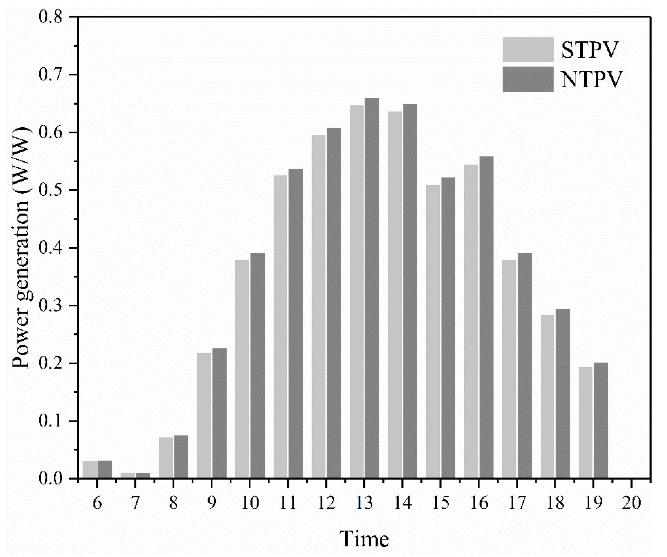
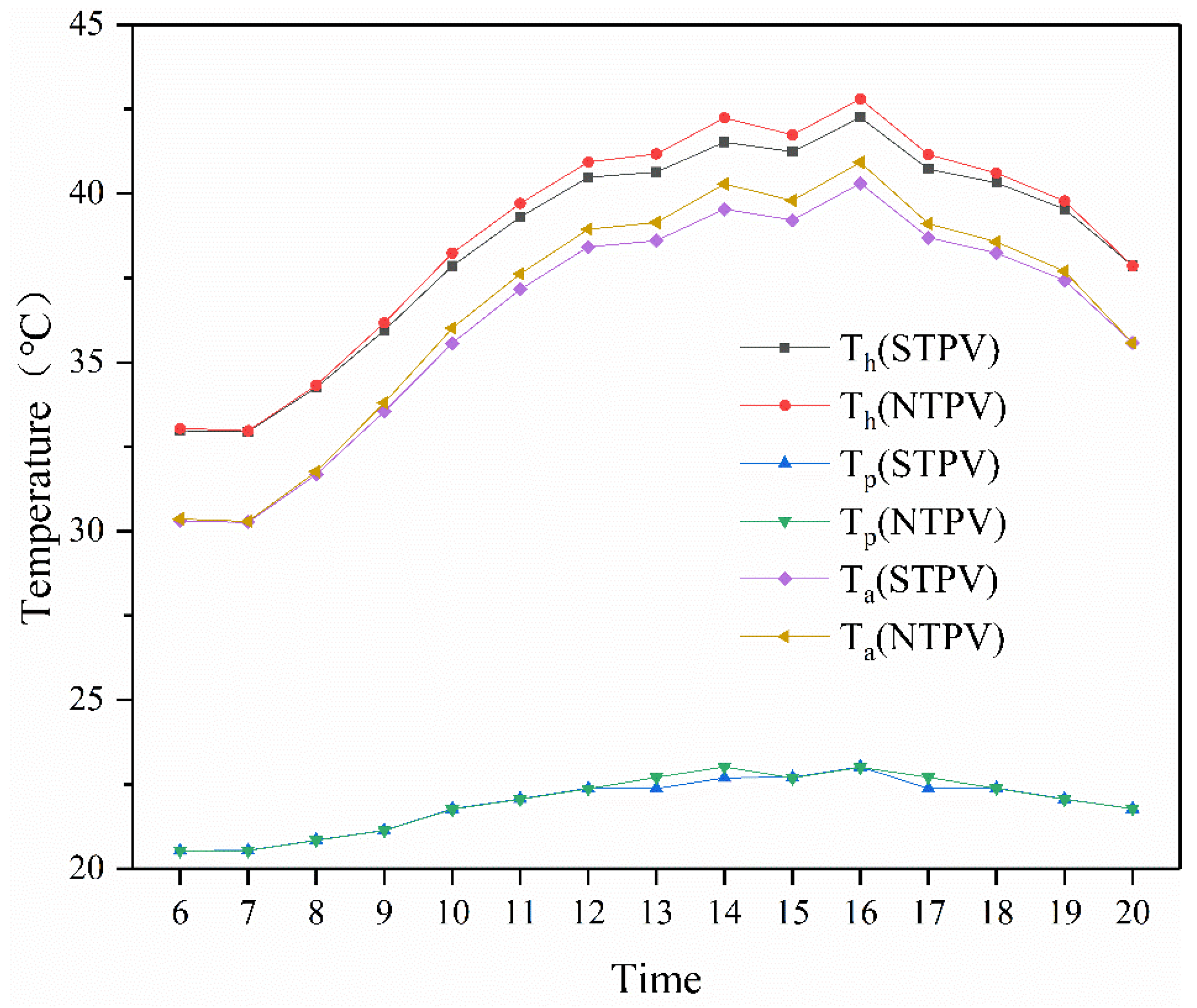
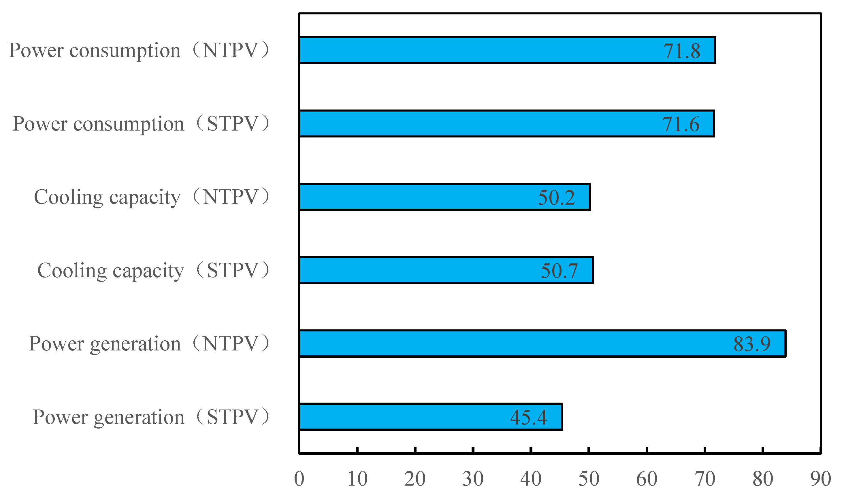
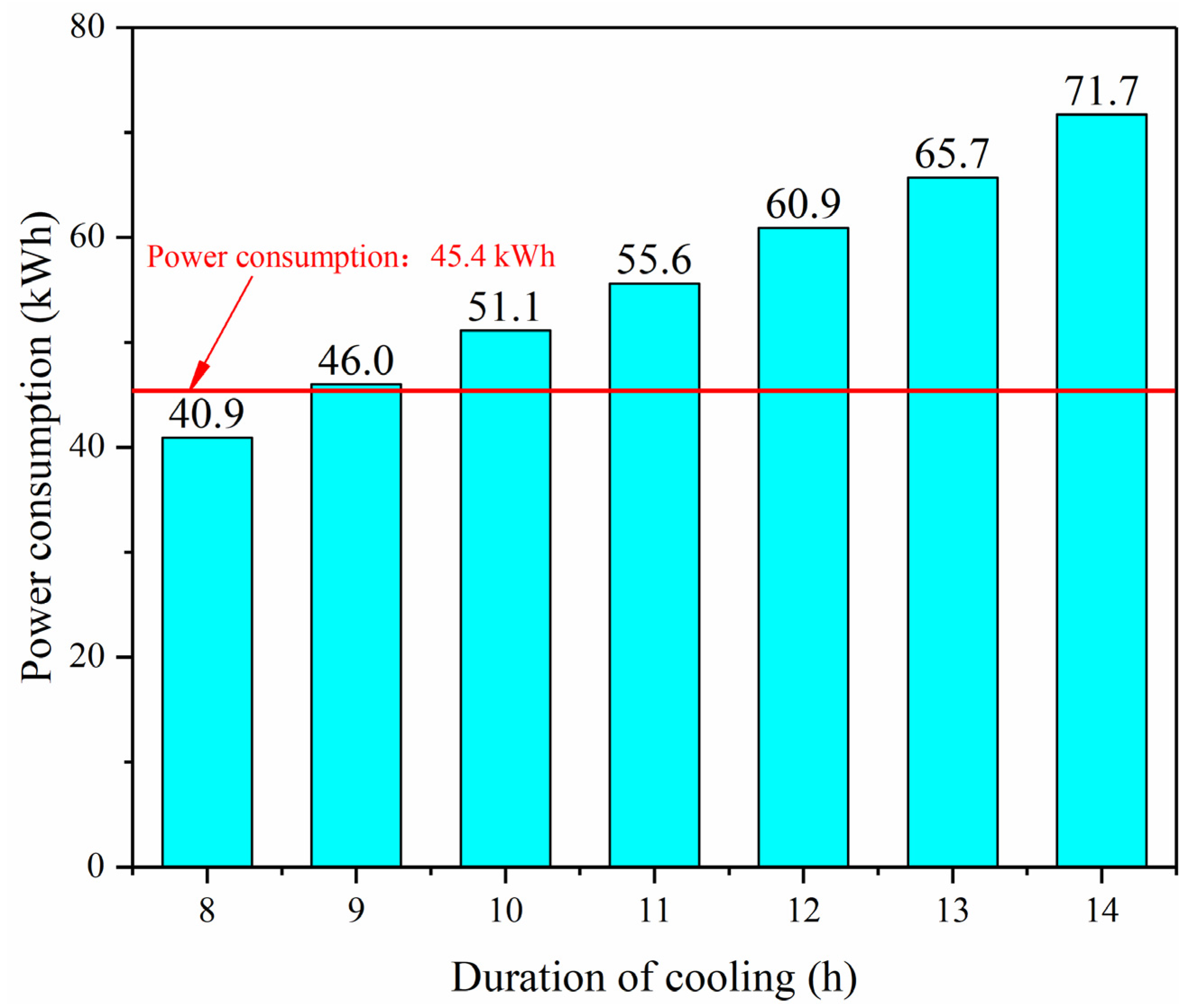
Comparing the effects of different PV modules on the PV-TEC window, numerical simulations were conducted for non-transparent photovoltaic modules (NTPV) and semi-transparent photovoltaic modules (STPV). The simulation results showed that different PV modules had little effect on the temperature of the components in the thermoelectric window, and the temperature difference was within 0.5 °C. The NTPV with a peak power of 270 W can meet the operating demand of the thermoelectric window, while the STPV with a peak power of 150 W can only meet the power consumption of the thermoelectric window with an operating time of less than 8 h.

Author Contributions

Writing—original draft preparation, W.Z.; validation, Y.Z. (Yuqiang Zhao); data curation, W.Z.; formal analysis, J.Z.; project administration, Y.Z. (Yongheng Zhong); software, J.Z.; writing—original draft, W.Z.; writing—review and editing, F.H. All authors have read and agreed to the published version of the manuscript.

Funding

The study was supported by the National Natural Science Foundation of China (Grant No. 51908287) and the National Natural Science Foundation of Jiangsu Province (Grant No. BK20180484).

Institutional Review Board Statement

Not applicable.

Informed Consent Statement

Not applicable.

Data Availability Statement

Not applicable.

Conflicts of Interest

The authors declare no conflict of interest.

References

  1. Euntae, Y.; Hend, O.M.; Sung-Gwan, P.; Obaid, M.; Siham, Y.A.-Q.; Pedro, C.; Kangmin, C.; Kyu-Jung, C. A review on self-sustainable microbial electrolysis cells for electro-biohydrogen production via coupling with carbon-neutral renewable energy technologies. Bioresour. Technol. 2021, 320, 124363. [Google Scholar]
  2. Prieto, A.; Knaack, U.; Klein, T.; Auer, T. 25 Years of cooling research in office buildings: Review for the integration of cooling strategies into the building façade (1990–2014). Renew. Sustain. Energy Rev. 2017, 71, 89–102. [Google Scholar] [CrossRef]
  3. Wei, H.; Su, Y.; Riffat, S.B.; Hou, J.X.; Jie, J. Parametrical analysis of the design and performance of a solar heat pipe thermoelectric generator unit. Appl. Energy 2011, 88, 5083–5089. [Google Scholar]
  4. Pei, G.; Fu, H.; Zhang, T.; Jie, J. A numerical and experimental study on a heat pipe pv/t system. Sol. Energy 2011, 85, 911–921. [Google Scholar]
  5. He, W.; Zhou, J.; Hou, J.; Chen, C.; Ji, J. Theoretical and experimental investigation on a thermoelectric cooling and heating system driven by solar. Appl. Energy 2013, 107, 89–97. [Google Scholar] [CrossRef]
  6. Shen, L.; Xiao, F.; Chen, H.; Wang, S. Investigation of a novel thermoelectric radiant air-conditioning system. Energy Build. 2013, 59, 123–132. [Google Scholar] [CrossRef]
  7. Di, L.; Fu-Yun, Z.; Guang-Fa, T. Active low-grade energy recovery potential for building energy conservation. Renew. Sustain. Energy Rev. 2010, 14, 2736–2747. [Google Scholar]
  8. Liu, Z.; Zhang, L.; Gong, G.; Han, T. Experimental evaluation of an active solar thermoelectric radiant wall system. Energy Convers. Manag. 2015, 94, 253–260. [Google Scholar] [CrossRef]
  9. Han, T.; Gong, G.; Liu, Z.; Ling, Z. Optimum design and experimental study of a thermoelectric ventilator. Appl. Therm. Eng. 2014, 67, 529–539. [Google Scholar] [CrossRef]
  10. Liu, Z.B.; Zhang, L.; Gong, G.C. Experimental evaluation of a solar thermoelectric cooled ceiling combined with displacement ventilation system. Energy Convers. Manag. 2014, 87, 559–565. [Google Scholar] [CrossRef]
  11. Zhang, J.; Zhang, W.; Huang, F.; Zhao, Y.; Zhong, Y. Research on factors and performance of solar thermoelectric radiant window. IOP Conf. Ser. Earth Environ. Sci. 2021, 675, 012083. [Google Scholar] [CrossRef]
  12. Xu, S.; Liao, W.; Huang, J.; Kang, J. Optimal PV cell coverage ratio for semi-transparent photovoltaics fades in central China on office building fac. Energy Build. 2014, 77, 130–138. [Google Scholar] [CrossRef]
  13. Shen, L.; Tu, Z.; Hu, Q.; Tao, C.; Chen, H. The optimization design and parametric study of thermoelectric radiant cooling and heating panel. Appl. Therm. Eng. 2017, 112, 688–697. [Google Scholar] [CrossRef]
  14. Liao, W. Comprehensive Energy Consumption Study of Translucent Monocrystalline Photovoltaic Glass in Building Applications; Huazhong University of Science and Technology: Wuhan, China, 2015. [Google Scholar]
  15. Daghigh, R.; Khaledian, Y. Effective design, theoretical and experimental assessment of a solar thermoelectric cooling-heating system. Sol. Energy 2018, 162, 561–572. [Google Scholar] [CrossRef]
  16. The American Society of Heating, Refrigeration and Air Conditioning Engineers (ASHRAE). Radiant Heating and Cooling. In ASHRAE Handbook: HVAC Systems and Equipment; ASHRAE: Peachtree Corners, GA, USA, 2016. [Google Scholar]
  17. Ministry of Housing and Urban-Rural Development. Design Code for Heating Ventilation and Air Conditioning in Civil Buildings; China Construction Industry Press: Beijing, China, 2012. [Google Scholar]
  18. Ministry of Housing and Urban-Rural Development. Technical Specification for Radiant Heating and Cooling; China Construction Industry Press: Beijing, China, 2012. [Google Scholar]
  19. Lim, H.; Jeong, J.W. Energy saving potential of thermoelectric modules integrated into liquid desiccant system for solution heating and cooling. Appl. Therm. Eng. 2018, 136, 49–62. [Google Scholar] [CrossRef]
  20. Han, L.; Kang, Y.K.; Jae-Weon, J. Thermoelectric radiant cooling panel design: Numerical simulation and experimental validation. Appl. Therm. Eng. 2018, 144, 248–261. [Google Scholar]
Figure 1. Structure of PV-TEC radiant window.
Energies 14 06645 g001
Figure 2. Flow chart of the numerical calculation of the PV-TEC radiant window.
Energies 14 06645 g002
Figure 3. Experimental platform of PV-TEC radiant windows. (a) Front side. (b) Lateral side.
Energies 14 06645 g003
Figure 4. Simulated and experimental values of PV-TEC radiant windows. (a) Indoor and outdoor weather parameters (b) Average temperature of radiant panels. (c) Temperature of cold and hot end of TEM. (d) Average temperature in air channels.
Energies 14 06645 g004
Figure 5. Temperature distribution clouds for thermoelectric radiation panels. (a) spacing: 0.38 m. (b) spacing: 0.36 m. (c) spacing: 0.34 m. (d) spacing: 0.32 m. (e) spacing: 0.30 m. (f) spacing: 0.28 m.
Energies 14 06645 g005aEnergies 14 06645 g005b
Figure 6. System cooling capacity and cooling performance at different radiant panel thicknesses.
Energies 14 06645 g006
Figure 7. Outdoor weather parameters on a typical summer day.
Energies 14 06645 g007
Figure 8. Power generation of the two modules.
Energies 14 06645 g008
Figure 9. Temperature of different components under two types of component power generation.
Energies 14 06645 g009
Figure 10. Cooling capacity and power consumption of the system.
Energies 14 06645 g010
Figure 11. Energy consumption of two types of PV modules.
Energies 14 06645 g011
Figure 12. Power consumption at different cooling durations with STPV supply.
Energies 14 06645 g012
Table 1. Thermal parameters of thermoelectric radiation panels.
Parameter Name (Unit)Numerical Value
Thermal conductivity of metallic radiation panels (W/(m·K))273
Specific heat capacity of metal radiation plate (J/(kg·K))880
Density of metal radiation plate (kg/m3)2730
Thickness of metal radiation plate (m)0.004
Integrated heat transfer coefficient of insulation material (W/(m2·K))0.109
Table 2. Nameplate parameters of PV.
Parameter Name (Unit)NTPVSTPV
Short-circuit current(A)9.228.88
Open-circuit voltage(V)37.921.3
Max. power point current(A)8.738.38
Max. power point voltage(V)30.917.9
Current temperature coefficient−0.06%−0.06%
Peak power(W)270150
Area of solar cells(m2)1.460.69
Publisher’s Note: MDPI stays neutral with regard to jurisdictional claims in published maps and institutional affiliations.

