Article

Parametric Study of a Supercritical CO2 Power Cycle for Waste Heat Recovery with Variation in Cold Temperature and Heat Source Temperature †

1
Research Division of Environmental and Energy Systems, Korea Institute of Machinery and Materials, 156 Gajeongbuk-ro, Yuseong-gu, Daejeon 34104, Korea
2
Department of Energy Technology, Korea Institute of Energy Technology (KENTECH), 200 Hyuksin-ro, Naju 58330, Korea
*
Author to whom correspondence should be addressed.
This article is based on a paper presented at the 33rd International Conference on Efficiency, Cost, Optimization, Simulation and Environmental Impact of Energy Systems held from 29 June to 3 July 2020.
Energies 2021, 14(20), 6648; https://doi.org/10.3390/en14206648
Submission received: 9 August 2021 / Revised: 21 September 2021 / Accepted: 11 October 2021 / Published: 14 October 2021
(This article belongs to the Special Issue Low-Temperature Thermodynamic Power Cycles)

Abstract

:
The supercritical carbon dioxide (S-CO2) power cycle is a promising development for waste heat recovery (WHR) due to its high efficiency despite its simplicity and compactness compared with a steam bottoming cycle. A simple recuperated S-CO2 power cycle cannot fully utilize the waste heat due to the trade-off between the heat recovery and thermal efficiency of the cycle. A split cycle in which the working fluid is preheated by the recuperator and the heat source separately can be used to maximize the power output from a given waste heat source. In this study, the operating conditions of split S-CO2 power cycles for waste heat recovery from a gas turbine and an engine were studied to accommodate the temperature variation of the heat sink and the waste heat source. The results show that it is vital to increase the low pressure of the cycle along with a corresponding increase in the cooling temperature to maintain the low-compression work near the critical point. The net power decreases by 6 to 9% for every 5 °C rise in the cooling temperature from 20 to 50 °C due to the decrease in heat recovery and thermal efficiency of the cycle. The effect of the heat-source temperature on the optimal low-pressure side was negligible, and the optimal high pressure of the cycle increased with an increase in the heat-source temperature. As the heat-source temperature increased in steps of 50 °C from 300 to 400 °C, the system efficiency increased by approximately 2% (absolute efficiency), and the net power significantly increased by 30 to 40%.

1. Introduction

A supercritical carbon dioxide (S-CO2) power cycle has been studied for diverse applications including nuclear, concentrated solar, fossil fuel, and waste heat recovery [1], and the S-CO2 power cycle has been optimized for each application [2]. The S-CO2 power cycle for waste heat recovery can lead to high cycle efficiencies and a substantial reduction in size compared to alternative power cycles. This can be promising for waste heat sources at temperatures beyond 300 °C and available thermal power from hundreds of kW to tens of MW [3,4] as the steam Rankine cycle requires its complicated structure and large size to achieve high cycle efficiency, and the ORC has a limitation of operating temperature below 300 °C to prevent the decomposition of the working fluid [5].
Huck et al. [6] compared the performance of an S-CO2 power cycle with steam bottoming cycles for gas turbine combined cycle applications. Although the S-CO2 bottoming cycle does not exceed the performance of a three-pressure reheat steam bottoming cycle for a heavy-duty gas turbine, it can outperform a two-pressure non-reheat steam cycle for an aeroderivative gas turbine. The sizes of the turbine and cooler (condenser) depend on the density of the expanded working fluid. The density of the expanded CO2 (above 50 bar) is tens of times higher than that of expanded steam (below 0.05 bar). The small size of the turbine and condenser compared to their steam equivalents permits a significantly reduced footprint and reduces the material cost of the components [7]. The smaller size and lighter weight of the system can have significant benefits for shipboard applications. Manjunath et al. [8] presented a novel waste heat recovery system for shipboard gas turbine exhaust for the simultaneous production of power and cooling using supercritical and transcritical CO2 cycles; the overall energy efficiency of the shipboard system increased by more than 11%.
In waste heat recovery (WHR), the purpose of cycle optimization is not to maximize the thermal efficiency of the cycle, but to maximize the power output from the waste heat source. It is essential to incorporate the thermal efficiency of the cycle (cycle efficiency) and the utilization efficiency of the waste heat (heat recovery efficiency) to maximize the power output of the WHR system from the given heat source (system efficiency) [9,10]. For cycle efficiency, it is essential to minimize the temperature difference for heat transfer (exergy loss). For heat recovery efficiency, it is essential to reduce the outlet temperature of the waste heat source as much as possible via waste heat recovery. Therefore, the optimal system configuration for achieving the maximum power from the waste heat source is different from that for a high-temperature heat source (nuclear, concentrated solar, and combustor) [10].
Wu et al. [5] proposed a novel type of single-pressure, multistage transcritical CO2 power cycle to overcome the shortcomings of the conventional transcritical CO2 power cycle in utilizing the waste heat of exhaust gas from a gas turbine or internal combustion engines. Moroz et al. [11] proposed several composite S-CO2 power cycles and compared their performance with sequential recompression and recuperated S-CO2 power cycles. Cho et al. [12] suggested several S-CO2 power cycles for the bottoming cycle of a combined-cycle gas turbine and compared the performance of the cycles with the reference steam cycle. Huck et al. [6] compared the performance of a dual-expansion and dual-flow split S-CO2 power cycle with three-pressure reheat-botting cycles for heavy-duty gas turbines.
Zhang et al. [13] presented a novel power cycle for the cascade utilization of waste heat from an offshore gas turbine and conducted a multi-objective optimization of the system to obtain the optimal operating parameters by considering the net power output and levelized energy cost as objective functions simultaneously. Sánchez et al. [14] carried out a thermoeconomic and thermoenvironmental analysis of an integrated thermal power plant using an S-CO2 partial heating Brayton cycle in a simple cycle thermal power plant.
Wright et al. [15] performed a thermoeconomic analysis of four S-CO2 power cycles (simple recuperated Brayton cycle, cascade cycle, dual recuperated cycle, and preheating cycle) and showed that all three WHR power cycles produced substantially more power and had larger annual revenue capabilities than the simple recuperated Brayton cycle. Cao et al. [16] reported that a novel gas turbine and cascade CO2 composed of an S-CO2 Brayton cycle and a transcritical CO2 cycle can increase the thermal efficiency by more than 17.03% from single gas turbine cycles. Manente et al. [17] investigated the potential of two novel WHR S-CO2 power cycles (single- and dual-flow split with dual expansion) and showed that the most advanced layout can increase the net power output from the given heat sources by 17.8–28.5%, which is 5.5–9.5% higher than that of traditional layouts, with an increase in the heat source temperature.
In our previous research [10], a split cycle in which the recuperator and heat source separately preheat the working fluid was proposed as a promising WHR cycle from a gas turbine. The split cycle was able to achieve higher efficiency at a lower upper pressure and lower turbine inlet temperature using a simpler system than the cascade cycle in which a low-temperature (LT) loop was added to the high-temperature (HT) loop of the simple recuperated S-CO2 power cycle.
The optimization and performance of the S-CO2 power cycle are significantly dependent on the cooling condition of the cycle as the cooling condition of CO2 before the compressor is very close to the critical point (31.1 °C and 73.9 bar), where the properties of CO2 change significantly. To minimize the compression work of the S-CO2 power cycle, Heo et al. [18] investigated the possibility of using an isothermal compressor and analyzed the cycle performance of the iso-Brayton cycle with an isothermal compressor and compared it with a simple recuperated Brayton cycle. Wright et al. [19] proposed an S-CO2 power cycle for gas turbine WHR combined with cold energy storage stored as ice in the charging cycle and then discharged by melting the ice for the cooling of the S-CO2 power cycle to reduce the compression work during the on-peak demand period.
Weiland et al. [20] investigated the effects of cold temperature on the performance of the S-CO2 recompression Brayton cycle (SRBC) employed for a coal-fired oxy-CFB power plant with carbon capture and considered the intercooling of the main compressor to reduce the compression work. However, the optimal conditions and performance of the S-CO2 recompression Brayton cycle for a high-temperature heat source are significantly different from those of the split S-CO2 power cycle for a gas turbine WHR in this study. Our previous studies on the S-CO2 power cycle for gas turbine WHR [10] were limited to a fixed cooling CO2 temperature of 20 °C (transcritical condition).
In this study, the operating conditions of the split S-CO2 power cycle for an aeroderivative gas turbine WHR were investigated to accommodate the temperature variation of the heat sink. The cooling conditions of the split S-CO2 power cycle are highly dependent on the site and season. In the case of shipboard applications, the cooling condition of the split S-CO2 power cycle varies during the day. In particular, when the cooling temperature of CO2 is higher than the critical temperature (31.1 °C), the split S-CO2 power cycle operates in the supercritical condition without a distinct phase change. With an increase in the cooling temperature of CO2, the low pressure of the cycle is carefully optimized for maximum net work (expansion work minus compression work), as the performance of the cycle varied significantly with variation in the low-pressure side of the cycle, and the characteristics of the optimization of the low-pressure side of the cycle with an increase in the cooling temperature of CO2 was explained in detail. Furthermore, to apply the split S-CO2 power cycle for WHR from an engine exhaust gas, the same parametric studies were performed to accommodate the temperature variation of the waste heat source from 300 to 400 °C as the temperature range represents the normal temperature of the exhaust gas of a marine diesel engine, and the temperature of the exhaust gas is dependent on the operating conditions of the engine. With variation of the waste heat source, the high-pressure side of the cycle is carefully optimized for the maximum net work, as it is typical that the optimal high pressure of the cycle in the split S-CO2 power decreases with a decrease in the heat source temperature. This is very different from the reheated and simple recuperated S-CO2 power cycles for engine waste heat recovery [21], in which a higher maximum pressure of up to 300 bar can always increase the net work of the cycles.

2. System Analysis

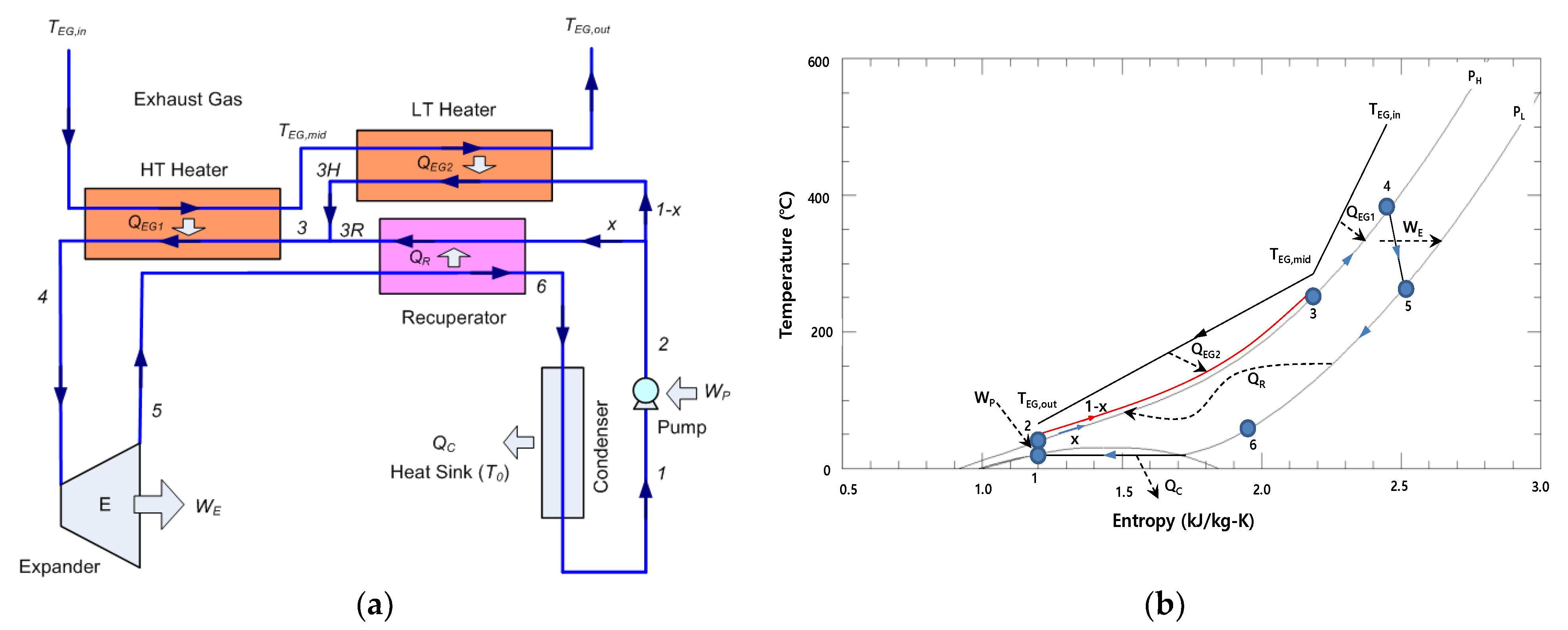
2.1. System Considered in Investigation

First, as a waste heat source, an exhaust gas with a mass flow rate of 69.8 kg/s at 538 °C (811 K) from a 25-MWe-class gas turbine was selected [19]. If the ambient temperature was 15 °C (288 K), then the corresponding amount of waste heat was 40.9 MWth. Second, an exhaust gas with a mass flow rate of 51 kg/s at 300 °C (up to 400 °C) from a 30-MWe-class engine was selected as the waste heat source (waste heat of 15.7 MWth).
Figure 1 shows the configuration and temperature-entropy (T-s) diagram, respectively, of a split S-CO2 power cycle for waste heat recovery (WHR) from a gas turbine [10]. A split S-CO2 power cycle was used to recover the remaining waste heat from the simple recuperated S-CO2 cycle and minimize the exergy loss in the recuperator. In the split S-CO2 power cycle for the WHR, the remaining waste heat from the HT heater was used to heat the high-pressure side of CO2 together with the recuperator as the isobaric specific heat of CO2 on the high-pressure side is much higher than that on the low-pressure side [10]. The portion denoted by x and the remaining (1 − x) portion after the pump are sent to the recuperator and LT heater, respectively, preheated to the same temperature, and merge before the HT heater. The pinch temperature (i.e., the minimum temperature difference required for heat transfer) was assumed to be 30 °C for the exhaust-gas-to-CO2 part and 10 °C for the internal recuperator.

2.2. Energy Analysis

The following general assumptions were made for the purpose of analysis: the kinetic and potential energies and the heat and friction losses were assumed to be negligible, both isentropic efficiencies of the pump and the turbine (expander) were assumed to be 80%, and the effectiveness of the recuperator was assumed to be 0.90 [10]. For a megawatt-class S-CO2 power cycle, the assumed isentropic efficiencies are reasonable and are based on values from the experimental results [22]. The pressure drops in the heat exchangers and pipes were assumed to be negligible. The model was considered as a steady-state model with a developed thermodynamic model in the Engineering Equation Solver (EES) software [23]. The properties of CO2 were obtained from REFPROP-NIST [24]. The variation in the cooling condition of the split S-CO2 cycle was considered as the variation in the inlet temperature of the pump (compressor). The equations for the different components of the split S-CO2 cycle shown in Figure 1 are as follows:
For the pump (compressor):
η P = h 2 , s h 1 h 2 h 1
W ˙ P + = m ˙ c o 2 ( h 2 h 1 )
For the turbine:
η T = h 4 h 5 h 4 , s h 5
W ˙ E = m ˙ c o 2 ( h 4 h 5 )
The efficiency of the recuperator, ε R , is expressed as follows:
ε R = m ˙ c o 2 ( h 5 h 6 ) Q ˙ m a x = m ˙ c o 2 ( h 3 h 2 ) Q ˙ m a x
The rate of maximum heat exchange, Q ˙ m a x , is expressed as follows:
Q ˙ m a x = m ˙ c o 2 ( h 5 h 6 )   assuming   T 6 = T 2
For the heater:
Q ˙ H + = m ˙ E G ( h E G , i n h E G , o u t ) = m ˙ c o 2 ( h 4 h 3 )
where m ˙ E G is the mass flow rate of the exhaust gas, and the subscripts in and out indicate the inlet and outlet states of the exhaust gas in the heater, respectively.
For the condenser:
Q ˙ C = m ˙ c o 2 ( h 6 h 1 )
For the thermal efficiency of the cycle:
η c y c = W ˙ E W ˙ P + Q ˙ H +
The heat recovery efficiency of WHR from a waste heat source can be defined as follows [7]:
η H R = Q ˙ H + Q ˙ H , m a x + = m ˙ w ( h in h out ) m ˙ w ( h in h 0 ) = h in h out h in h 0
where Q ˙ h , m a x is the maximum allowable heat rate from the waste heat source; is the mass flow rate of the waste heat source; h in and h out are the inlet and outlet specific enthalpies of the waste heat source, respectively, and the subscript 0 indicates that the properties are taken at the reference temperature and pressure ( T 0 , P 0 ) representing the dead state.
The thermal efficiency of the WHR system can be defined as the ratio of the net power to the maximum allowable heating rate from the waste heat source [9]. The efficiency is expressed as follows:
η s y s = W ˙ E W ˙ P + Q ˙ H , m a x + = η H R η c y c

3. Split Supercritical CO2 Rankine Cycle for Waste Heat Recovery

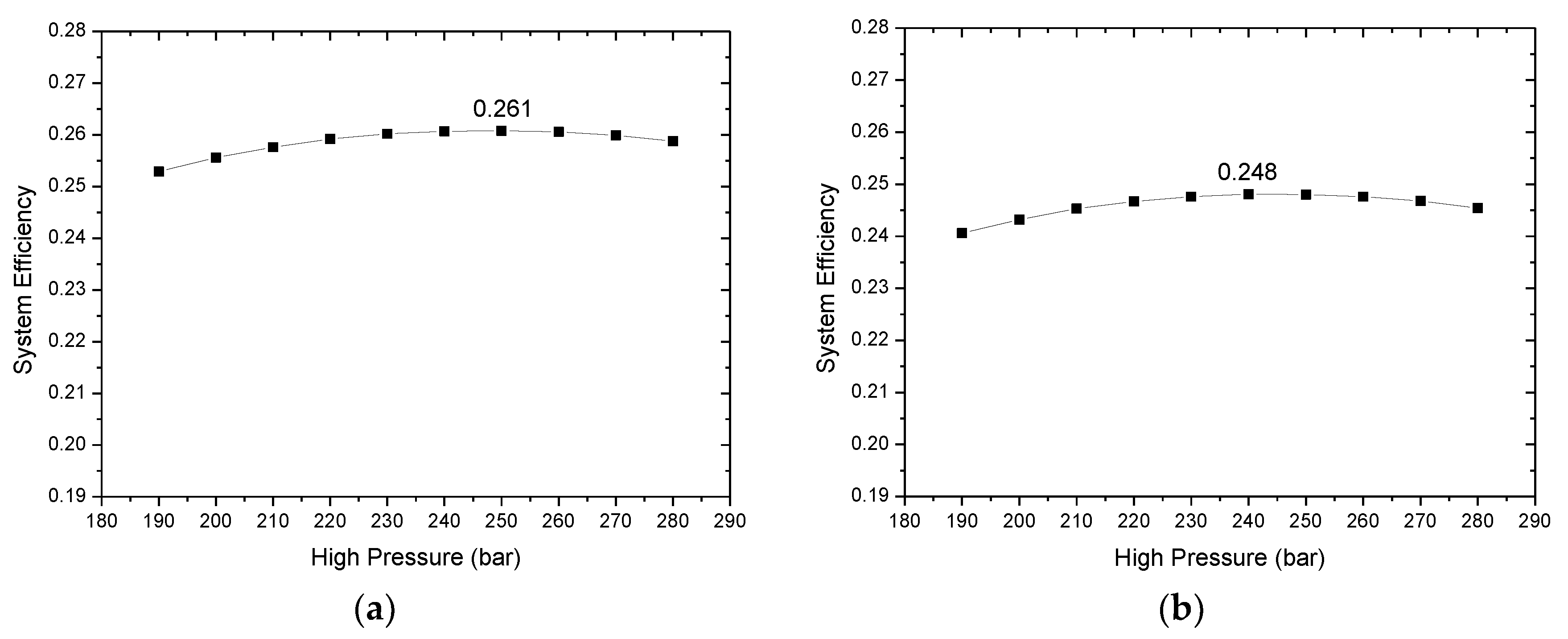
3.1. Parametric Study of Cycle

A parametric study of the WHR cycle must be performed for maximum system efficiency by incorporating the heat recovery (HR) efficiency with the cycle efficiency to obtain the maximum power from the waste heat source. At a given cooling condition (temperature) of CO2 and the low- and high-pressure sides, the system efficiency was obtained for the increases in the turbine inlet temperature, when the mass flow rate of the working fluid and the split ratio x (the portion that flows to the recuperator) are adjusted to meet the pinch temperatures for the exhaust gas-to-CO2 part (30 °C) and the internal recuperator (10 °C) [10]. With an increase in the turbine inlet temperature, as shown in Figure 2, the cycle efficiency increases, but the HR efficiency decreases. Due to this trade-off relationship, the system efficiency increases and decreases, and has a peak point in the middle range of the turbine inlet temperature. Thus, the optimal turbine inlet temperature for the maximum system efficiency can be obtained.
At a given cooling temperature of CO2 below the critical temperature (in the case of the transcritical CO2 power cycle), the low-pressure side can be easily optimized to be close to the saturation pressure. Therefore, the high-pressure side must be optimized, together with the optimal turbine inlet temperature. Figure 3 shows the system efficiency of the WHR CO2 power cycle from the gas turbine at cooling temperatures of 20 °C and 25 °C of CO2 for a rise at the high-pressure side.
At a given cooling temperature of CO2 close to and above the critical temperature (in the case of the supercritical CO2 power cycle), both the low- and high-pressure sides must be optimized with the optimal turbine inlet temperature. Figure 4 shows the system efficiency of the WHR CO2 power cycle from the gas turbine at cooling temperatures of 30 °C, 35 °C, 40 °C, and 50 °C of CO2 for a rise at the high-pressure side with the given low-pressure side.

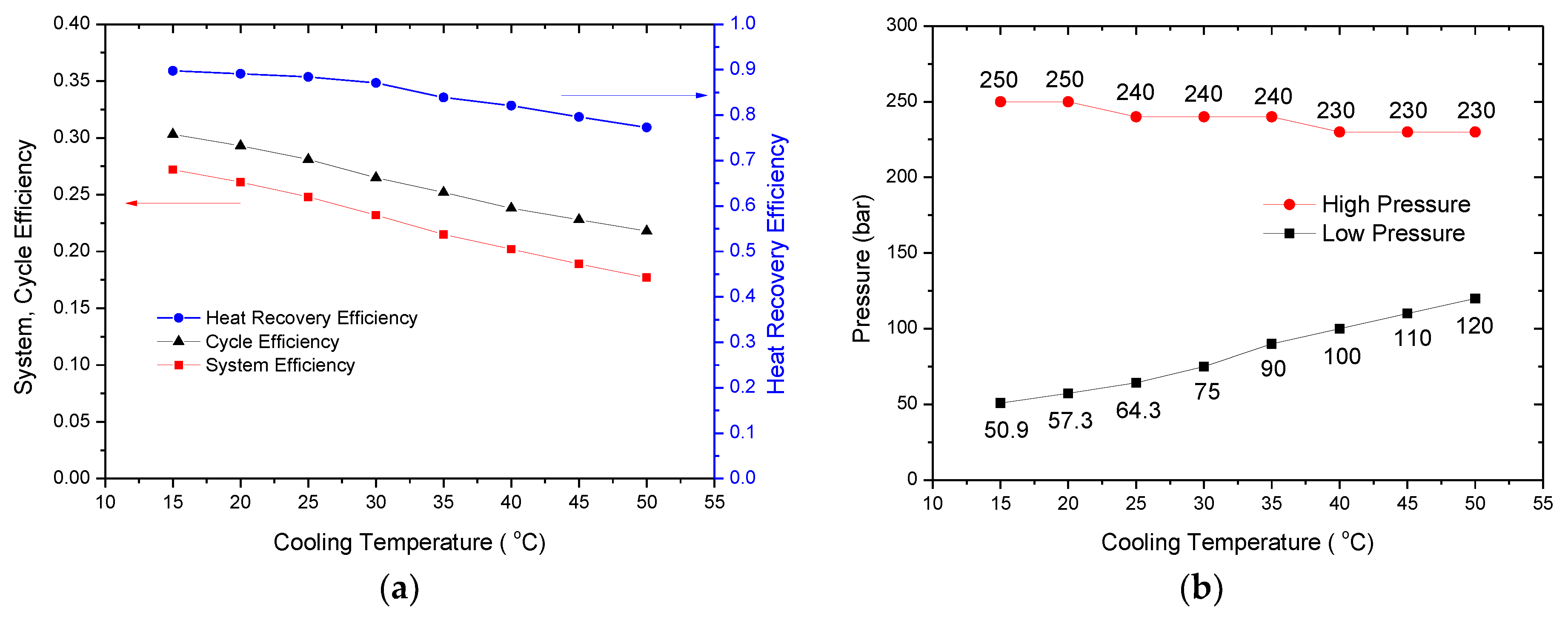
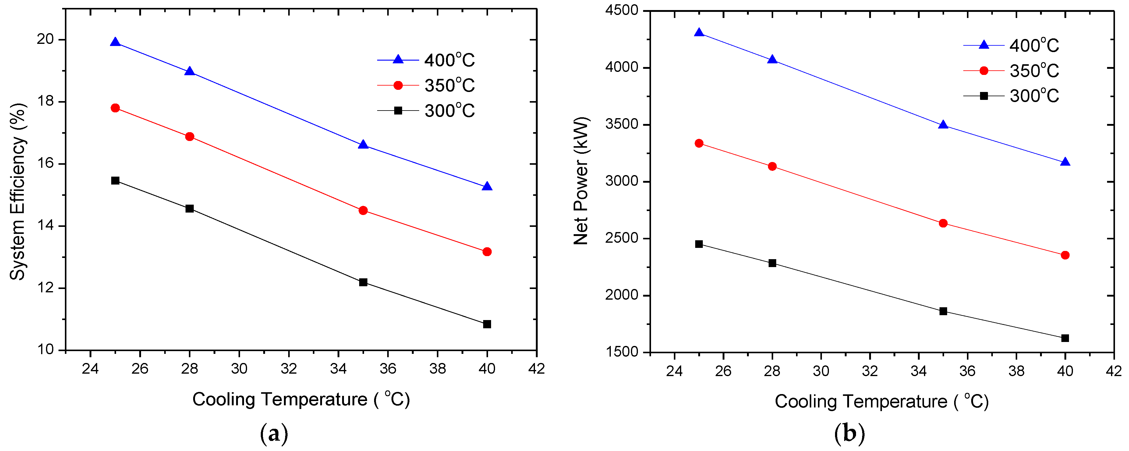
3.2. Effects of Cooling Temperature

From the previous optimization of the operating conditions including both the low- and high-pressure sides and the turbine inlet temperature, for maximum power from the waste heat source, the maximum system efficiency at a given cooling temperature of CO2 can be obtained. This is shown in Figure 5a. The cycle efficiency decreases with the heat recovery efficiency during an increase in the cooling temperature of CO2. Therefore, the system efficiency decreases by 4 to 7% with an increase of 5 °C in the cooling temperature of CO2.
The optimal high- and low-pressure sides for the maximum system efficiency at a given cooling temperature of CO2 are shown in Figure 5b. The effect of the cooling temperature on the optimal high-pressure side is insignificant, as the optimal high pressure of the cycle is in the range of 230 to 250 bar, and the maximum system efficiency of the split cycle has a very flat curve over the wide range of the high-pressure side, as shown in Figure 3 and Figure 4. However, the optimal low pressure of the cycle must be increased with an increase in the cooling temperature of CO2, as shown in Figure 5b, as the effect of the low-pressure side on the maximum system efficiency of the split cycle is significant, as shown in Figure 3 and Figure 4.
The compression processes from the optimal low-pressure side to the optimal high-pressure side with an increase in the cooling temperature are located in the T-s diagram, as shown in Figure 6a. The optimal low-pressure states before compression are located in the diagram of the constant pressure-specific heat (cp) over the range of the cooling temperature of CO2, as shown in Figure 6b. The low pressure of the cycle must be increased to maintain a liquid-like state of S-CO2 before compression with an increase in the cooling temperature of CO2. In the supercritical region, there is no distinct phase-change period. However, the left-hand side of the pseudocritical line vertical to the critical point is close to a liquid-like state, and the right-hand side is close to a gaseous-like state. In Figure 6b, the peak points of constant pressure-specific heat (cp) correspond to the pseudocritical line (pseudocritical temperature and pressure). The optimal low-pressure state before compression at a given cooling temperature of CO2, as shown in Figure 6b, must be located well before the pseudocritical point in order to reduce the compression work. Therefore, as shown in Figure 7a, the optimal low pressure of the cycle before compression in the supercritical region is higher than the pseudocritical pressure at a given cooling temperature of CO2. The net power (Wnet) decreases by 6–9% with every 5 °C rise in the cooling temperature of CO2 from 20 to 50 °C, as shown in Figure 7b, as the compression work (Wc) increases, and the expansion work (We) decreases.

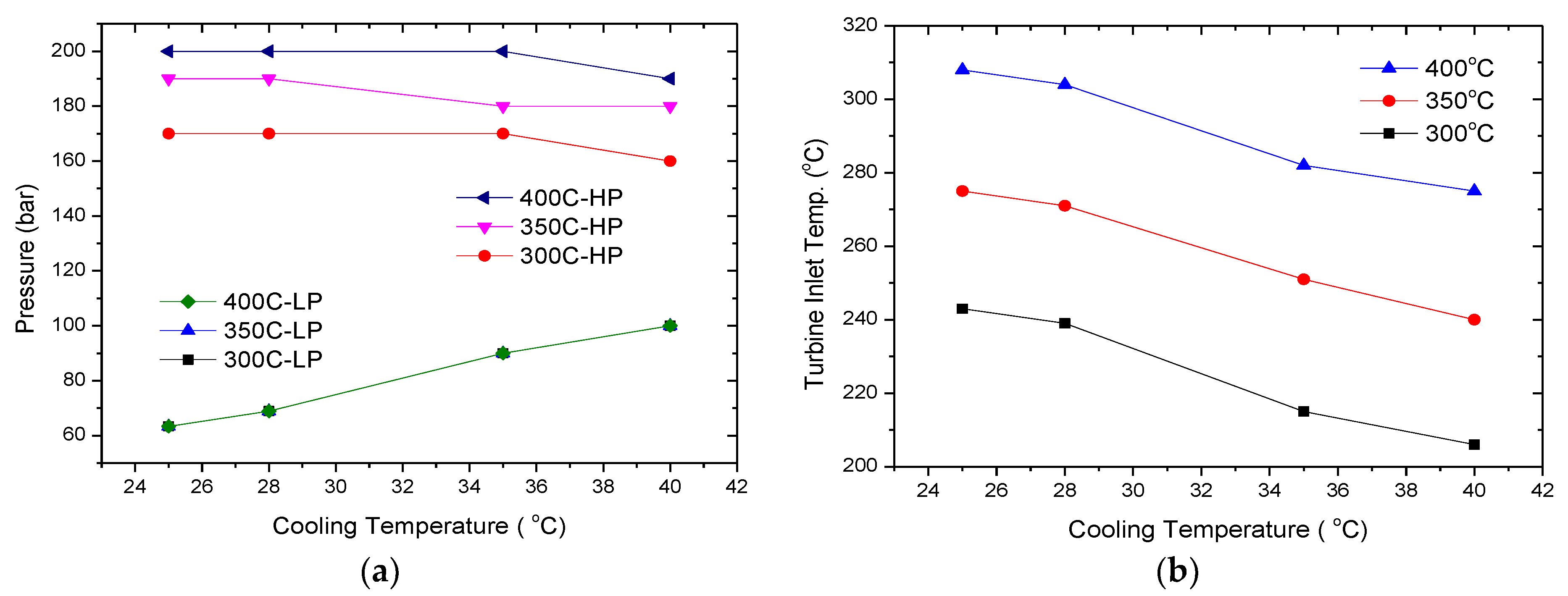
3.3. Effects of Heat Source Temperature

An exhaust gas with a mass flow rate of 51 kg/s from 300 to 400 °C from a 30-MWe-class engine was selected as the waste heat source to investigate the effects of the heat source temperature on the WHR split S-CO2 cycle. Similar to the previous parametric study of the cycle, the optimal low- and high-pressure sides can be obtained at a given exhaust gas temperature from 300 to 400 °C, as shown in Figure 8a. The effect of the heat source temperature on the optimal low-pressure side is negligible, and the optimal low-pressure side is dependent on the cooling temperature of CO2. However, the optimal high-pressure of the cycle increases with an increase in the heat source temperature, and is much lower than the previous case with a higher temperature of the exhaust gas from the gas turbine (230 to 250 bar). The optimal turbine inlet temperature increases with an increase in the heat source temperature and decreases with an increase in the cooling temperature of CO2, as shown in Figure 8b.
Figure 9 shows the maximum system efficiency and net power of the WHR split S-CO2 cycle with an increase in the heat source temperature. As the heat source temperature increases in steps of 50 °C from 300 to 400 °C, the system efficiency increased by approximately 2% (absolute efficiency), and the net power significantly increased by 30 to 40%.

4. Conclusions

In our previous research, a split S-CO2 cycle was proposed as a promising WHR cycle for a gas turbine. The split S-CO2 power cycle can recover the remaining waste heat from the simple recuperated S-CO2 cycle and compensate for the large difference in the specific heat of CO2 between the high- and low-pressure sides in the recuperator. Although the split S-CO2 power cycle for WHR is very different from the conventional S-CO2 power cycle for a high-temperature heat source (nuclear, concentrated solar, and combustor), knowledge of the split S-CO2 power cycle for WHR is very limited. In this study, the operating conditions of the split S-CO2 power cycle for WHR from an aeroderivative gas turbine was optimized to accommodate the temperature variation of the heat sink, and the performance of the cycle was analyzed. In the S-CO2 power cycle, the effects of the cooling condition close to the critical point on the optimization of the operating conditions and the performance of the cycle are significant. Furthermore, to apply the split S-CO2 power cycle for WHR from an engine exhaust gas, the operating conditions of the cycle were optimized to accommodate the temperature variation of the waste heat source, and the performance of the cycle was analyzed.
With an increase in the cooling temperature of CO2, the low pressure of the cycle before compression must be increased to maintain a liquid-like state of S-CO2 in the supercritical region to reduce the compression work and maintain the liquid-like state before compression well before the pseudocritical point (peak point of the specific heat). However, the effect of the cooling temperature on the optimal high-pressure side was insignificant. The net power of the cycle decreases by 6 to 9% with every 5 °C rise in the cooling temperature of CO2 from 20 to 50 °C due to the decrease in heat recovery and thermal efficiency of the cycle.
In the same manner, the operating conditions of the split S-CO2 cycle were optimized for WHR from an engine exhaust gas from 300 to 400 °C, and the optimal low- and high-pressure sides were obtained at a given exhaust gas temperature. The effect of the heat source temperature on the optimal low-pressure side was negligible, and the optimal low-pressure side was dependent on the cooling temperature of CO2. However, the optimal high pressure of the cycle decreases with a decrease in the heat source temperature, and is much lower than in the previous case with a higher temperature of the exhaust gas from a gas turbine. This characteristic is very peculiar and different from the reheated and simple recuperated S-CO2 power cycles for engine WHR, in which a higher maximum pressure of up to 300 bar can always increase the net work of the cycles. As the heat source temperature increases in steps of 50 °C from 300 to 400 °C, the system efficiency increases by approximately 2% (absolute efficiency), and the net power significantly increases by 30 to 40%.

Author Contributions

All authors contributed to this study. Y.-M.K. designed the model of the system and performed the analysis of the system. Y.-D.L. and K.-Y.A. discussed the results and commented on the manuscript at all stages. All authors have read and agreed to the published version of the manuscript.

Funding

This research was funded by Korea Institute of Machinery and Materials Research Fund, 2020 (NK225A).

Institutional Review Board Statement

Not applicable.

Informed Consent Statement

Not applicable.

Data Availability Statement

Not applicable.

Conflicts of Interest

The authors declare no conflict of interest.

Nomenclature

Isobaric specific heat, kJ/kg·K
hSpecific enthalpy, kJ/kg
Mass flow rate, kg/s
PPressure, kPa
Rate of heat, kW
TTemperature, °C
Rate of work, kW
Special characters
Heat exchanger effectiveness
ηEfficiency
Subscripts and superscripts
0Atmospheric (environmental) state
CCondenser
cycCycle
eExpander
EGExhaust gas
HHeater
HRHeat recovery
iState point
ininlet
maxMaximum
netNet output
outOutlet
PPump
RRecuperator
sIsentropic process
sysSystem
TTurbine
+Input
Output

References

  1. Ahn, Y.; Bae, S.J.; Kim, M.; Cho, S.K.; Baik, S.; Lee, J.I.; Cha, J.E. Review of Supercritical CO2 Power Cycle Technology and Current Status of Research and Development. Nucl. Eng. Technol. 2015, 47, 647–661. [Google Scholar] [CrossRef] [Green Version]
  2. Kim, S.; Cho, Y.; Kim, M.S.; Kim, M. Characteristics and Optimization of Supercritical CO2 Recompression Power Cycle and the Influence of Pinch Point Temperature Difference of Recuperators. Energy. 2018, 147, 1216–1226. [Google Scholar] [CrossRef]
  3. Marchionni, M.; Bianchi, G.; Tassou, S.A. Review of Supercritical Carbon Dioxide (sCO2) Technologies for High-Grade Waste Heat to Power Conversion. SN Appl. Sci. 2020, 2, 611. [Google Scholar] [CrossRef] [Green Version]
  4. Liu, L.; Yang, Q.; Cui, G. Supercritical Carbon Dioxide(s-CO2) Power Cycle for Waste Heat Recovery: A Review from Thermodynamic Perspective. Processes 2020, 8, 1461. [Google Scholar] [CrossRef]
  5. Wu, C.; Yan, X.-J.; Wang, S.-S.; Bai, K.-L.; Di, J.; Cheng, S.-F.; Li, J. System Optimisation and Performance Analysis of CO2 Transcritical Power Cycle for Waste Heat Recovery. Energy 2016, 100, 391–400. [Google Scholar] [CrossRef]
  6. Huck, P.; Freund, S.; Lehar, M.; Peter, M. Performance Comparison of Supercritical CO2 Versus Steam Bottoming Cycles for Gas Turbine Combined Cycle Applications. In Proceedings of the 5th International Symposium—Supercritical CO2 Power Cycles, San Antonio, TX, USA, 28–31 March 2016. [Google Scholar]
  7. Held, T.J. Supercritical CO2 cycles for gas turbine combined cycle power plants. In Proceedings of the Power Gen International, Las Vegas, NV, USA, 8–10 December 2015. [Google Scholar]
  8. Manjunath, K.; Sharma, O.P.; Tyagi, S.K.; Kaushik, S.C. Thermodynamic Analysis of a Supercritical/Transcritical CO2—Based Waste Heat Recovery Cycle for Shipboard Power and Cooling Applications. Energy Convers. Manag. 2018, 155, 262–275. [Google Scholar] [CrossRef]
  9. Kim, Y.M.; Shin, D.G.; Kim, C.G.; Cho, G.B. Single-Loop Organic Rankine Cycles for Engine Waste Heat Recovery Using Both Low- and High-Temperature Heat Sources. Energy 2016, 96, 482–494. [Google Scholar] [CrossRef]
  10. Kim, Y.M.; Sohn, J.L.; Yoon, E.S. Supercritical CO2 Rankine Cycles for Waste Heat Recovery from Gas Turbine. Energy 2017, 118, 893–905. [Google Scholar] [CrossRef]
  11. Moroz, L.; Burlaka, M.; Rudenko, O.; Joly, C. Evaluation of Gas Turbine Exhaust Heat Recovery Utilizing Composite Supercritical CO2 Cycle. In Proceedings of the International Gas Turbine Congress, Tokyo, Japan, 15–20 November 2015. [Google Scholar]
  12. Cho, S.K.; Kim, M.; Baik, S.; Ahn, Y.; Ik Lee, J. Investigation of the Bottoming Cycle for High Efficiency Combined Cycle Gas Turbine System with Supercritical Carbon Dioxide Power Cycle. In Proceedings of the ASME Turbo Expo: Turbine Technical Conference and Exposition GT, Montréal, QC, Canada, 15–19 June 2015. [Google Scholar]
  13. Zhang, Q.; Ogren, R.M.; Kong, S. Thermo-Economic Analysis and Multi-Objective Optimization of a Novel Waste Heat Recovery System with a Transcritical CO2 Cycle for Offshore Gas Turbine Application. Energy Convers. Manag. 2018, 172, 212–227. [Google Scholar] [CrossRef]
  14. Sánchez Villafana, E.D.; Vargas Machuca Bueno, J.P. Thermoeconomic and Environmental Analysis and Optimization of the Supercritical CO2 Cycle Integration in a Simple Cycle Power Plant. Appl. Therm. Eng. 2019, 152, 1–12. [Google Scholar] [CrossRef]
  15. Wright, S.; Davidson, C.; Scammell, W. Thermo-Economic Analysis of Four sCO2 Waste Heat Recovery Power Systems. In Proceedings of the 5th International Symposium on Supercritical CO2 Power Cycles, San Antonio, TX, USA, 28–31 March 2016. [Google Scholar]
  16. Cao, Y.; Ren, J.; Sang, Y.; Dai, Y. Thermodynamic Analysis and Optimization of a Gas Turbine and Cascade CO2 Combined Cycle. Energy Convers. Manag. 2017, 144, 193–204. [Google Scholar] [CrossRef]
  17. Manente, G.; Fortuna, F.M. Supercritical CO2 Power Cycles for Waste Heat Recovery: A Systematic Comparison Between Traditional and Novel Layouts with Dual Expansion. Energy Convers. Manag. 2019, 197, 111777. [Google Scholar] [CrossRef]
  18. Heo, J.Y.; Ahn, Y.; Lee, J.I. A Study of S-CO2 Power Cycle for Waste Heat Recovery Using Isothermal Compressor. In Proceedings of the ASME Turbo Expo: Turbomach, Technical Conference and Exposition GT, Seoul, Korea, 13–17 June 2016. [Google Scholar]
  19. Wright, S.A.; Davidson, C.S.; Scammell, W.O. Bulk Energy Storage Using a Supercritical CO2 Waste Heat Recovery Power Plant. In Proceedings of the 4th International Symposium—Supercritical CO2 Power Cycles, Pittsburg, PA, USA, 9–10 September 2014. [Google Scholar]
  20. Weiland, N.T.; White, C.W.; O’Connell, A.C. Effects of Cold Temperature and Main Compression Intercooling on Recuperator and Recompression Cycle Performance. In Proceedings of the 2nd European sCO2 Conference, Essen, Germany, 30–31 August 2018; Volume 2018. [Google Scholar]
  21. Hossain, M.J.; Chowdhury, J.I.; Balta-Ozkan, N.; Asfand, F.; Saadon, S.; Imran, M. Design optimization of supercritical carbon-dioxide (s-CO2) cycles for waste heat recovery from marine engines. J. Energy Resour. Technol. 2021, 143, 120901. [Google Scholar] [CrossRef]
  22. Held, T.J. Initial test results of a megawatt-class supercritical CO2 heat engine. In Proceedings of the 4th International Symposium—Supercritical CO2 Power Cycles, Pittsburg, PA, USA, 9–10 September 2014. [Google Scholar]
  23. F-Chart Software, Engineering Equation Solver (EES). 2019. Available online: http://www.fchart.com/ees (accessed on 1 August 2021).
  24. Lemmon, E.W.; Mclinden, M.O.; Huber, M.L. NIST Standard Reference Database 23, Version 10.0, Reference Fluid Thermodynamic and Transport Properties-REFPROP; National Institute of Standards and Technology (NIST): Boulder, CO, USA, 2018; Volume 23.
Figure 1. Split S-CO2 power cycle for WHR from exhaust gas: (a) Schematic; (b) T-s diagram [10].
Energies 14 06648 g001
Figure 2. Optimization of turbine inlet temperature for maximum system efficiency of split S-CO2 power cycle.
Energies 14 06648 g002
Figure 3. System efficiency of S-CO2 power cycle for high-pressure side at given cooling temperature: (a) 20 °C; (b) 25 °C.
Energies 14 06648 g003
Figure 4. System efficiency of S-CO2 power cycle for high-pressure side at given cooling temperature: (a) 30 °C; (b) 35 °C; (c) 40 °C; and (d) 50 °C.
Energies 14 06648 g004
Figure 5. Optimal operating condition and performance of S-CO2 power cycle for given cooling temperature: (a) HR, cycle, and system efficiency; (b) low- and high-pressure sides.
Energies 14 06648 g005
Figure 6. Optimal compression process of S-CO2 power cycle for given cooling temperature: (a) T-s diagram; (b) constant specific heat (cp) vs. temperature and low-pressure sides before compression.
Energies 14 06648 g006
Figure 7. Optimal compression process of S-CO2 power cycle for given cooling temperature: (a) optimal low-pressure side; (b) compression, expansion, and net work.
Energies 14 06648 g007
Figure 8. Optimal operating condition of S-CO2 power cycle for given exhaust gas temperature from engine: (a) Low-pressure (LP) and high-pressure (HP) sides; (b) turbine inlet temperature.
Energies 14 06648 g008
Figure 9. Performance of S-CO2 power cycle for given exhaust gas temperature from engine: (a) System efficiency; (b) net power.
Energies 14 06648 g009
Publisher’s Note: MDPI stays neutral with regard to jurisdictional claims in published maps and institutional affiliations.

