Article

Influence of Operation Conditions on Temperature Hazard of Lithium-Iron-Phosphate (LiFePO4) Cells

by
Wojciech Kurpiel
1,*,
Bartosz Polnik
1,
Łukasz Orzech
1,
Krzysztof Lesiak
1,
Bogdan Miedziński
2,
Marcin Habrych
2,
Grzegorz Debita
3,
Monika Zamłyńska
3 and
Przemysław Falkowski-Gilski
4
1
KOMAG Institute of Mining Technology, Pszczynska St. 37, 44-101 Gliwice, Poland
2
Faculty of Electrical Engineering, Wroclaw University of Science and Technology, Wybrzeze Wyspianskiego St. 27, 50-370 Wroclaw, Poland
3
Faculty of Management, General Tadeusz Kosciuszko Military University of Land Forces, Czajkowskiego St. 109, 51-147 Wroclaw, Poland
4
Faculty of Electronics, Telecommunications and Informatics, Gdansk University of Technology, Narutowicza St. 11/12, 80-233 Gdansk, Poland
*
Author to whom correspondence should be addressed.
Energies 2021, 14(20), 6728; https://doi.org/10.3390/en14206728
Submission received: 5 September 2021 / Revised: 1 October 2021 / Accepted: 4 October 2021 / Published: 15 October 2021
(This article belongs to the Special Issue The KOMTECH-IMTech 2021 Mining Technologies Future)

Abstract

:
The article presents and discusses the results of research on hazard, especially temperature, for selected lithium-ion-phosphate cells operated in accordance with the manufacturer’s recommendations but used under onerous mining conditions. This applies to the performance of cells in battery sets without the application of any management system (BMS). On the basis of the obtained test results, first of all, the influence of the value of the charging current of cells and the ambient temperature for both free and deteriorated heat exchange, appropriate conclusions and practical recommendations were formulated. This applies especially to threats in the case of random, cyclic, minor overloading, and discharging of the cells.

1. Introduction

The search for batteries of a large capacity, small dimensions, and weight as well as respective properties to meet the requirement of a wide application resulted in advanced structures of lithium-iron-phosphate batteries of a different type [1,2,3]. The differences in design and technology are mainly due to various requirements related to operating conditions and different durability required, reaching 10 years. Lithium-iron-phosphate batteries are a more long-lasting and safer variant of any other lithium-ion batteries on the market. They do not display the so-called memory effect [4,5]. The self-discharge current value is small, therefore, their long life can be achieved [6,7,8,9,10]. However, one should note that, as for all other energy sources, improper use can result in its rapid damage, which, in turn, increases the threat of the operational safety of the devices being supplied. It is particularly important under fire and/or explosion risks such as those that occur, for example, in underground mines, especially methane ones. Therefore, the replacement of any lead-acid batteries with lithium-iron-phosphate ones, particularly in mining equipment, must be preceded by careful considerations based on respective investigations [2]. Damage to lithium-iron-phosphate batteries can be manifested by loss of capacity, gas ejection, ignition, and in extreme cases, explosion. It is dangerous for all applications, but in hard coal mines with a risk of coal dust or methane explosion, it may have unimaginable consequences. Such situations are most often associated with the short circuits of the battery electrodes and resulted heating up to temperatures exceeding the permissible value specified by the manufacturer. The appearance of short circuits is enhanced by various internal defects, such as burrs on the electrode foils, their punctures, or contaminations [7]. However, the deep discharge and temperature hazard are the key factors primarily degrading the life duration and safe operation of lithium-iron-phosphorus batteries. To keep the long life of lithium-iron-phosphorus batteries, one has to constantly ensure the optimal operating temperature, usually around 20 °C. Too high a temperature value usually results in accelerated aging of the battery, whereas a low one prevents it from performing with the required capacity. However, effective operation under low temperature is related to the risk of damage to the battery as well. The intensity of chemical reactions lowers as the temperature drops, which decreases the current efficiency (effective charge) of the battery. On the other hand, the use of batteries at temperatures above the value specified by the manufacturer is also not recommended, mainly due to safety reasons. This is especially important when the battery consists of many (e.g., hundreds) cells as their cooling conditions are unequal and/or practically limited. This is due to the decomposition effect of lithium above the critical temperature for a given type of cell. The passive layer that separates the negative electrode from the electrolyte can thus be disturbed. This significantly enhances an exothermic reaction of graphite with the electrolyte, which may result in an increase in the gas pressure inside. This causes the cell to swell or enhances the gas leakage through the safety valve. Thus, if only the cell contains free oxygen (due to the heating of decompositions of the cathode matrix), the ignition and/or the explosion of the cell can take place easily. Therefore, the battery packs are often equipped with special cooling and heating systems, to ensure optimal operating temperature [11,12,13,14,15]. The risk related to the use of different types of lithium-iron-phosphorus batteries in various operating conditions is of great importance. This usually applies to extreme conditions such as significant overloading, deep discharging, burdensome temperature conditions, etc. It was found, for example, that the potential severity of incidents during storage, transport, and recycling of waste batteries can be significantly higher than in end-use applications. Safe storage, packaging, and labeling practices, as well as communication among the parties involved, are essential to ensure safety across the battery lifecycle [16]. In the paper [17], analytical and modeling methods to estimate explosion characteristics, such as lower flammability limit, laminar flame speed, and maximum over-pressure, are evaluated for use in quantifying the effect of cell chemistry, state-of-charge, and other parameters on the overall explosion hazard potential for confined cells. Several hazard relevant parameters of a failing currently used battery cell extracted from a modern mass-production such as the temperature response of the cell, the maximum reached cell surface temperature, the amount of produced vent gas, the gas venting rate, the composition of the produced gases, including electrolyte vapor and the size and composition particles at thermal runaway are the subject of the article [18]. The problem of temperature risk during a significant increase of the discharge current value is, for example, the subject of research and detailed analyses of the published article [19].
The aim of the article was to evaluate the possibility of successful and safe replacement of lead batteries with lithium-iron-phosphate ones in the power supply system of a mine suspended battery vehicle, as an example. It would allow increasing the engine operation time with a significantly reduced weight and fulfill all in regards to work safety in an underground mine, with hard coal and the risk of coal dust fire and/or methane explosion. The lithium-iron-phosphate batteries were selected from lithium-ion batteries currently available on the market. They are characterized by the highest operational reliability confirmed under mining operating conditions, creating the lowest risk of fire and/or explosion. For this reason, they are formally permitted for use in mines by the superior controlling mining institution [20,21]. It is well known that the increase in temperature value of lithium-iron-phosphate cells is particularly significant under the cells overloading. Therefore, in practice, such cases are not allowed to do so by using, inter alia, appropriate protections [22]. The authors have found, however, that the increase in cell temperature may also be risky under undisturbed operating conditions. It is particularly important under heavy-duty work, especially when heat dissipation to the environment is significantly reduced. Such a case may be of great importance in the analyzed application.
The article presents an analysis and tests results of the temperature value and its distribution over the casing of lithium-iron-phosphate cells and their correlation with the cell voltage during normal operation and following discharging to the minimum voltage. The structure of the mining machine in which the lead-acid batteries are to be replaced with lithium-iron-phosphate batteries is described in Section 2. The scope and method of conducted research are presented in Section 3. The tests were performed both under normal room conditions (20 °C) and for different (positive) ambient temperatures (+5 °C to +60 °C) with constant humidity (75%) and for free heat dissipation to the environment. Their results, along with the relevant discussion, are presented in Section 3. Particular attention was paid to the performance of cells for limited cooling during small overloadings (an increase of the load current above the rated value) as well as discharges that were repeated accidentally (impuls discharges) but quite often in time what is a novelty. This threat is the result of a fairly large thermal inertia of the tested cells and is unavoidable in mining applications. On the basis of the obtained research results, respective practical conclusions were formulated and are presented in the last Section 4.

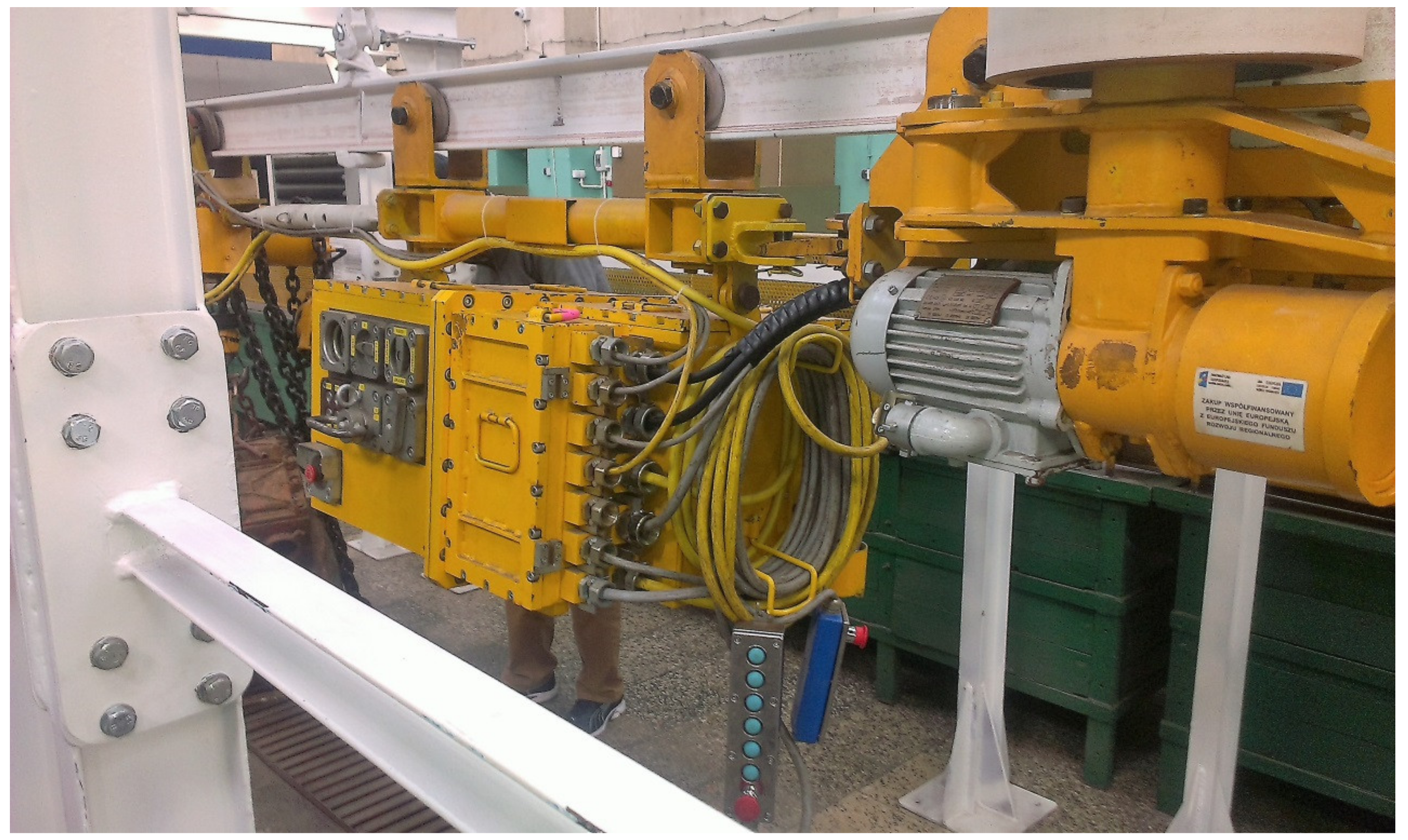
2. Considered Application to Mining Machine

Taking into account both the increase of working safety conditions and a significant reduction in weight, it was decided to consider the possibility of the effective and safe use of lithium-iron-phosphate batteries in a suspended mining vehicle (carrying engine), the structure as indicated in Figure 1.
The suspended battery-powered vehicle (PCA-1) consists of a driving trolley 1, power supply unit 2, which is composed of battery pack and other electrical appliances (for control, security, charging systems, electronic systems, etc.), control cassettes 3 (alternatively radio remote control panel) and the braking trolley 4. The carrying engine may be equipped with an additional arrangement that does not constitute basic equipment, such as a cabin for transporting people, transport beams, etc. A general view of the suspended battery vehicle is presented in Figure 2.
Based on experience, it was decided that as the power source for the PCA-1 battery vehicles, a lithium-iron-phosphate battery will be selected. It was composed of cells connected in series to provide the voltage level of 48 V DC. The battery units of resultant energy of 150 kWh were predicted to be housed inside a special box for protection. However, in closed housing, the cooling conditions significantly deteriorated. This was unfavorable, particularly when the cells that make up the batteries are packed tightly (as seen in Figure 3). The cells located centrally will be the most at risk since they are additionally heated by the surrounding cells.
In such cases, an online temperature (and voltage) control of each cell is essential, with the optional use of a gas sensor (so-called smart nose [23]) if possible.

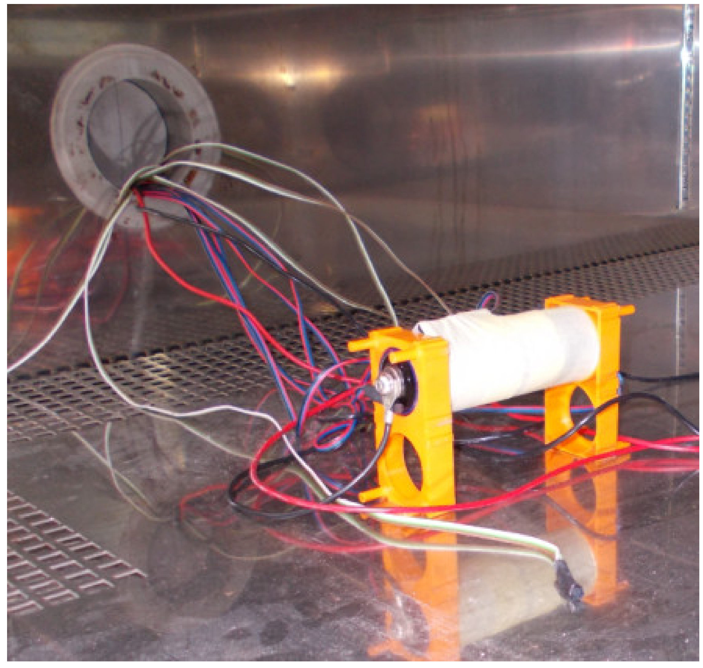
3. The Scope and Method of Conducted Research
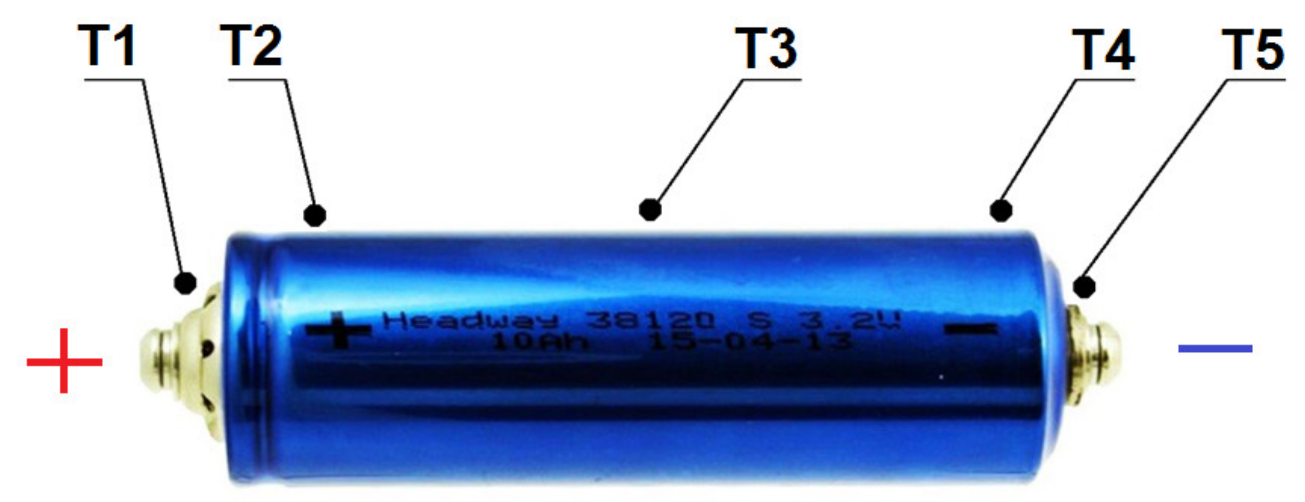
The tests were carried out for Headway LFP38120 (S) lithium-iron-phosphate cells with temperature sensors appropriately arranged on the housing, as shown in Figure 4.
Basic cell technical data [24]:
  • ▪ Voltage: 3.2 V,
  • ▪ Capacity: 10 Ah,
  • ▪ Internal resistance: <6 mOhm,
  • ▪ Charging voltage: 3.65 ± 0.05 V,
  • ▪ Energy density: 105 Wh/kg,
  • ▪ Technology: lithium-iron-phosphate (LiFePO4),
  • ▪ Maximum discharge voltage: 2.5–2.0 V,
  • ▪ Range of operational temperatures:
    • ▪ Charging: 0 ÷ 45 °C,
    • ▪ Discharging: −20 ÷ 65 °C,
  • ▪ Life: over 2000 cycles (80% of capacity when loading with 10 A current).
Analog device sensors of a temperature range from −50 °C to +150 °C were used under the tests. They did not need any sophisticated equipment and/or external calibration to be carried out [25]. The tests were carried out both for cells operating under room temperature (about 20 °C) with free heat dissipation to ambient, for fixed constant environmental conditions (temperature and humidity), as well as for limited cooling (deteriorated heat outflow to the environment). Since under real working conditions, the cells may not be charged equally, the temperature was measured for different values of the initial load current lower than its standard discharge level and varied from about 12% to around 50% of its value. The measurements were commenced each time for fully charged cells, i.e., started from the rated voltage Un, equal to 3.2 V, and lasted until the voltage was dropped down to the minimum value of Umin specified by the manufacturer (equal to 2.5 V). The research on the influence of the ambient temperature on the performance of the cell was carried out in a climatic chamber (see Figure 5).
For a fixed humidity equal to 75%, the ambient temperature was stepwise adjustable in the range from +5 °C to +60 °C. The load current was selected to be 3.8 A, which is around 40% of the standard discharge value. The influence of deteriorated cell cooling was examined in simulated conditions by wrapping the cell’s casing with appropriate thermal insulation and placing the whole in a styrofoam housing, as indicated in Figure 6.
The performance of the cell in the case of its full discharge (to around 9% of the rated value) was also examined. Such a situation can often be met in practice when, e.g., the operator forgets to disconnect the load. The tests were performed for three cells of the same type. Each measurement of both the temperature at T1 and the cell voltage was repeated five times, calculating the mean values with a confidence level of 0.95 using the Student’s Test [26].

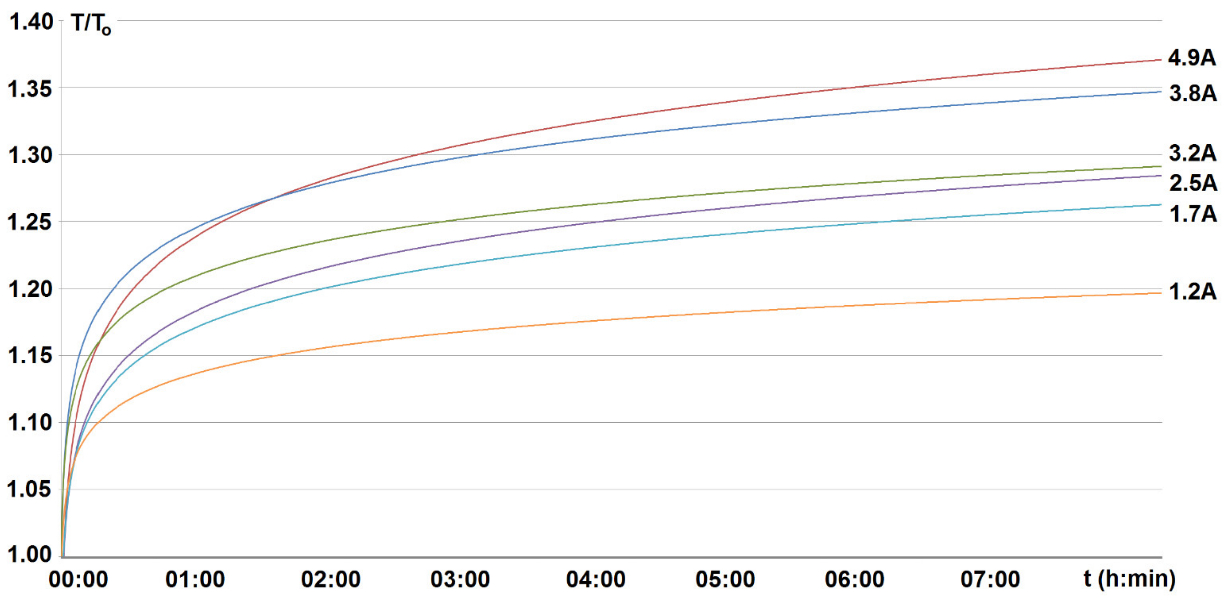
4. Investigated Results and Discussion

The cell temperature under each test was found to be the highest at point T1 (close to the positive pole—Figure 4). At other casing points, it showed no significant deviations and was slightly lower (on average by about ±10%). Therefore, point T1 was considered as the most critical from the point of view of control of the cell performance. Thus, all the presented measurement results refer to it. Before starting the research, the behavior of the cells during their slight overcharging was checked. Such a situation may arise in practice. Therefore, the slightly higher charging voltage (4.38 V), by about 20% than recommended by the manufacturer (3.65 V), was employed. However, for smaller (by about 10%) current value, compared to standard charge ones recommended by the manufacturer in order not to overheat [27]. The selected current of around 4.5 A was found to be practically constant throughout the charging process regardless of the variable value of the charging voltage with time, including its stabilization after about 25 min (see Figure 7). From the measured waveforms of the charging voltage and temperature at point T1, shown in this figure, it is seen that the temperature increases exponentially depending on the cell’s heat capacity and environmental conditions. Due to the thermal time constant of the cell, the temperature keeps increasing for some time after switching off the charging. Therefore, after about 10 min from switching off the voltage, the cell casing temperature exceeds the ambient one by about 70%. Thus, even short-term, small overcharging, especially repeated over time, may pose a significant threat to the operation of batteries and devices powered from them. It may lead to explosion of the battery and, as a result, to fire in the mine, particularly methane ones. To verify the load influence, the appropriate tests were carried out for the different constant values of the discharge currents at room temperature (around 20 °C) while ensuring free cooling.
It is obvious that under real working conditions, the cells may be loaded with different current values depending on the nature of the work. Therefore, variation with time of the cell voltage value and the course of heating may be of a very different nature during operation. The cells were fully charged, and the tests continued until the voltage dropped to the minimum value (2.5 V). During loading, the current was practically constant over time (regardless of the set values) and started to drop down when the voltage decreased to a value close to its minimum (Umin = 2.5 V). For the load current equal to 4.9 A, this is shown, for example, in Figure 8.
The measured changes in the voltage of the cells and the temperature rise with time are shown in Figure 9 and Figure 10.
For discharge current not over 50% of the standard value of the tested cells (10 A), the cells heat up relatively little. The temperature value for the highest discharge current equal to 4.9 A reached about 31 °C when the voltage dropped to the minimum discharge value of 2.5 V (Figure 9). However, the time to the allowed maximum discharge (minimum value of the cell voltage) was found to be linearly dependent on the current value, which can be compared from Figure 10. When examining the behavior of cells in a climate chamber with a constant, set temperature (+5 °C ÷ +60 °C) and humidity value (around 75%) and a constant value of the discharge current (around 40% of its standard value), it was found that the temperature rises slightly above the ambient temperature. On the other hand, the time of the voltage drop to the minimum value practically does not change in the range of temperatures above room temperature (+20 °C ÷ +60 °C). For lower temperature, however, the cells discharge is faster, which can be compared from the measured curve U = f(t) shown in Figure 11 for an ambient temperature of around +5 °C.
The research shows that increasing the cell temperature (up to about +60 °C) practically does not affect the duration of its discharge. On the other hand, it is much more unfavorable for decreased casing temperature (+5 °C), which shortens as a result of the duration of the discharge time (by about 10%) to the voltage minimum value (see Figure 11).
In the case of deep discharge, the visible increase in cell temperature is seen at the moment the voltage begins to decline. Then, despite the decrease in the value of the current (and voltage), the temperature continues to increase, reaching the maximum (about +43 °C) after some time (t4) due to the thermal inertia of the tested cells. The cell voltage starts to rebuild immediately after the load is turned off (t5—see Figure 12). It should be noted at this point that it takes a relatively long time to decrease the temperature from its maximum to room value (several hours). As a result, the cell housing shows an increasingly higher temperature with each subsequent recharge. This can be a significant hazard under certain operating conditions.

5. Conclusions

The conducted tests showed that the operation of the tested cells under room conditions with free heat exchange does not pose any threats if the discharge current does not exceed 50% of the standard value. The cell temperature increases exponentially with the current. However, when the minimum voltage value Umin is reached, it does not exceed +30 °C. It is a value accepted by the manufacturer. Of course, as the current increases, the discharge time of the cell decreases practically linearly. The increased temperature of the environment from +5 °C to +60 °C sets the temperature of the cell at the same level. However, for temperature in the range of +20 °C ÷ +60 °C, practically no effect was found if the discharge duration for the same current value was not exceeding 40% of the standard ones. On the contrary, at lowered ambient temperature, the discharge time decreases. For example, lowering the temperature from +20 °C to +5 °C shortens this time by about 10%.
Small one-time overcharges (about 20% of the voltage) and random short-term deep discharges (up to about 10% of the voltage and the current below 50% of the standard current) do not pose a significant threat. It is all the more important as the cells operate more effectively in the upper-temperature range (up to +65 °C). Such cases, however, should be carefully controlled and prevented, as their repetition leads to a significant increase in the cell temperature above the allowable. This is due, among other things, to the high thermal inertia of the tested cells. Therefore, the tested cells are suitable for use as the power supply source of selected mining machines but provided with the application of an effective battery management (BMS) system.

Author Contributions

Conceptualization, W.K. and B.P.; methodology, W.K. and Ł.O.; software, P.F.-G. and M.Z.; validation, M.H., B.M. and K.L.; investigation, W.K. and B.P.; resources, G.D., M.Z. and Ł.O.; writing—original draft preparation, W.K., B.M. and B.P.; visualization, W.K. and M.H. All authors have read and agreed to the published version of the manuscript.

Funding

The paper received no external funding.

Institutional Review Board Statement

Not applicable.

Informed Consent Statement

Not applicable.

Data Availability Statement

Not applicable.

Conflicts of Interest

The authors declare no conflict of interest.

References

  1. Kurpiel, W.; Polnik, B.; Miedziński, B. Właściwości eksploatacyjne ogniw litowych. Elektro Info 2018, 10, 44–48. [Google Scholar]
  2. Polnik, B. Tests of the Hk-1 Module of the Mobile Mining Machine. ECS Trans. 2019, 95, 389–396. [Google Scholar] [CrossRef]
  3. Omar, N.; Monem, M.A.; Firouz, Y.; Salminen, J.; Smekens, J.; Hegazy, O.; Gaulous, H.; Mulder, G.; Van den Bossche, P.; Coosemans, T.; et al. Lithium iron phosphate based battery—Assesment of the aging parameters and development of cycle life model. Appl. Energy 2014, 113, 1575–1585. [Google Scholar] [CrossRef]
  4. Vetter, J.; Novak, P.; Wagner, M.R.; Veit, C.; Möller, K.C.; Besenhard, J.O.; Winter, M.; Wohlfahrt-Mehrens, M.; Vogler, C.; Hammouche, A. Ageing mechanisms in lithium-ion batteries. J. Power Sources 2005, 147, 269–281. [Google Scholar] [CrossRef]
  5. Santhanagopalan, S.; Kim, G.H.; Keyers, M.; Pesaran, A.; Smith, K.; Neubauer, J. Design and Analysis of Large Lithium-Ion Battery Systems; Artech House: London, UK, 2015; pp. 81–93. [Google Scholar]
  6. Cadar, D.V.; Petreus, D.M.; Patarau, T.M. An Energy Converter Method for Battery Cell Balancing. In Proceedings of the IEEE 33rd International Spring Seminar on Electronics Technology (ISSE), Warsaw, Poland, 12–16 May 2010; pp. 290–293. [Google Scholar]
  7. Gabano, J.P. Lithium Batteries; JohnWiley & Sons, Inc.: Hoboken, NJ, USA, 2013. [Google Scholar]
  8. Ehrlich, G.M. Lithium-Ion Batteries. In Handbook of Batteries, 3rd ed.; Linden, D., Reddy, T., Eds.; McGraw-Hill: New York, NY, USA, 2002; pp. 53–59. [Google Scholar]
  9. Aurbach, J.D. Review of Selected Electrode-Solution Interactions with Determine the Performance of Li and Li Ion Batteries. Power Sources 2000, 89, 206. [Google Scholar] [CrossRef]
  10. Schalkwijk, W.V.; Scrosati, B. Advances in Lithium-Ion Batteries; Kluwer Academic/Plenum Publishers: New York, NY, USA, 2002. [Google Scholar]
  11. Zhang, Z.J.; Ramadass, P.; Fang, W. Safety of Lithium-Ion Batteries. In Lithium-Ion Batteries: Advances and Applications; Pistoia, G., Ed.; Elsevier: Amsterdam, The Netherlands, 2014. [Google Scholar]
  12. Levy, S.C. Safety and Reliability Considerations for Lithium Batteries. J. Power Sources 1997, 68, 75–77. [Google Scholar] [CrossRef]
  13. Zhang, S.S. A Review on Electrolyte Additives for Lithium-Ion Batteries. J. Power Sources 2006, 162, 1379–1394. [Google Scholar] [CrossRef]
  14. Yoshino, A. Development of the Lithium-Ion Battery and Recent Technological Trends. In Lithium-Ion Batteries: Advances and Applications; Pistoia, G., Ed.; Elsevier: Amsterdam, The Netherlands, 2014. [Google Scholar]
  15. Zaghib, K.; Mauger, A.; Julien, C.M. Rechargeable lithium batteries for energy storage in smart grids. In Rechargeable Lithium Batteries; Franco, A., Ed.; Elsevier: Amsterdam, The Netherlands, 2015. [Google Scholar]
  16. Salminen, J.; Kallio, T.; Omar, N.; Van den Bossche, P.; Van Mierlo, J.; Gualous, H. Transport Energy—Lithium Ion Batteries. In Future Energy; Letcher, T., Ed.; Elsevier: Amsterdam, The Netherlands, 2014. [Google Scholar]
  17. Lisbona, D.; Snee, T. A review of hazards associated with primary lithium and lithium-ion batteries. Process Saf. Environ. Prot. 2011, 89, 434–442. [Google Scholar] [CrossRef]
  18. Baird, A.R.; Archibald, E.J.; Marr, K.C.; Ezekoye, O.A. Explosion hazards from lithium-ion battery vent gas. J. Power Sources 2020, 446, 227257. [Google Scholar] [CrossRef]
  19. Essl, C.; Golubkov, A.W.; Gasser, E.; Nachtnebel, M.; Zankel, A.; Ewert, E.; Fuchs, A. Comprehensive hazard analysis of failing automotive Lithium-ion batteries in overtemperature experiments. Batteries 2020, 6, 30. [Google Scholar] [CrossRef]
  20. Ouyang, D.; Liu, J.; Chen, M.; Wang, J. Investigation into the fire hazards of lithium-ion batteries under overcharging. Appl. Sci. 2017, 7, 1314. [Google Scholar] [CrossRef] [Green Version]
  21. Spinner, N.S.; Hinnant, K.M.; Tuttle, S.G.; Rose-Pehrsson, S.L. Lithium-Ion Battery Failure: Effects of State of Charge and Packing Configuration; Naval Research Laboratory: Arlington, VA, USA, 2016; p. 21. [Google Scholar]
  22. Yoshio, M.; Brodd, R.J.; Kozawa, A. Lithium-Ion Batteries: Science and Technologies; Springer: New York, NY, USA, 2009. [Google Scholar]
  23. Perner, A.; Vetter, J. Post-Lithium-ion batteries for hybrid electric vehicles and battery electric vehicles. In Advances in Battery Technologies for Electric Vehicles; Scrosati, B., Garche, J., Tillmetz, W., Eds.; Elsevier: Amsterdam, The Netherlands, 2015. [Google Scholar]
  24. Documentation of Battery LiFePO4 3.2 V. Available online: https://www.bto.pl/produkt/31801/headway-lfp38120(s)-10000mah-lifepo4 (accessed on 5 August 2021).
  25. Documentation of Voltage Output Temperature Sensor with Signal Conditioning. Available online: https://www.analog.com/en/products/ad22100.html# (accessed on 5 August 2021).
  26. Taylor, R.J. Introduction to Error Analysis, the Study of Uncertainties in Physical Measurements, 2nd ed.; University Science Books: Sausalito, CA, USA, 1997. [Google Scholar]
  27. Montanino, M.; Passerini, S.; Appetecchi, G.B. Electrolytes for rechargeable lithium batteries. In Rechargeable Lithium Batteries; Franco, A.A., Ed.; Elsevier: Amsterdam, The Netherlands, 2015. [Google Scholar]
Figure 1. Layout of the suspended battery vehicle (PCA-1) (1—driving trolley, 2—power supply unit, which includes battery bank and necessary auxiliary devices such as control, security, charging systems, electronic systems, etc., 3—control cassettes or alternatively radio remote control panel, 4—braking trolley.
Energies 14 06728 g001
Figure 2. General view of the suspended battery vehicle PCA-1.
Energies 14 06728 g002
Figure 3. Illustrative arrangement of cells in an enclosure with limited cooling.
Energies 14 06728 g003
Figure 4. Arrangement of temperature sensors on the tested cell.
Energies 14 06728 g004
Figure 5. The climatic chamber stands for testing the influence of temperature on cell performance.
Energies 14 06728 g005
Figure 6. Layout for cells testing under restricted conditions of heat transfer.
Energies 14 06728 g006
Figure 7. The temperature (T1 sensor-blue line), load current (green line, Ispr is a standard discharge current equal to 10 A), and cell (LiFePO4) voltage U/Un (red line) variation as a function of time during the overcharging (voltage Umax over 37%) (rated Un = 3.2 V, ambient temperature T0 = 22 °C, t1, t2—time of switching the charger on and off, t3—time of the maximum temperature Tmax = 37 °C).
Energies 14 06728 g007
Figure 8. Current (I) and voltage (U) waveforms over time when loaded with current of 4.9 A under free ambient conditions (T0 = 22 °C).
Energies 14 06728 g008
Figure 9. Increase in cell temperature T (T1 sensor) during discharge (to the minimum voltage value Umin equal to 2.5 V) for various load currents under free room conditions. (T0 = 22 °C).
Energies 14 06728 g009
Figure 10. Variation of cell voltage U with time versus the load current (1.2–4.9 A) for a constant ambient temperature (about 22 °C). Umin = 2.5 V.
Energies 14 06728 g010
Figure 11. Time of voltage decrease to the minimum value (Umin = 2.5 V) depending on the ambient temperature (+5 ÷ +60 °C) at 3.8 A constant current.
Energies 14 06728 g011
Figure 12. Variation of voltage U (red line), current I (green line ), and temperature value (blue line, T1) of a cell with time during deep discharge (to around 10% of rated voltage value Un) for a constant load current Iobc of 3.8 A; (room temperature T0 = 22 °C, free cooling; t1,t5—moment of switching on and off the load current respectively, t2—temperature Td (33 °C) at the minimum voltage value recorded at t3; t4-time of maximum temperature Tmax (43 °C)).
Energies 14 06728 g012
Publisher’s Note: MDPI stays neutral with regard to jurisdictional claims in published maps and institutional affiliations.

