Article

Numerical Study on Influences of Drag Reducing Additive in Supercritical Flow of Kerosene in a Millichannel

1
Harbin Institute of Technology, School of Energy Science and Engineering, 92 West Dazhi Rd, Harbin 150001, China
2
Centre d’Énergétique et de Thermique de Lyon, Institut National des Sciences Appliquées de Lyon, CEDEX, F-69621 Villeurbanne, France
3
Laboratory of Thermo-Fluid Science and Nuclear Engineering, Northeast Electric Power University, Jilin 132012, China
4
School of Energy and Power Engineering, Northeast Electric Power University, Jilin 132012, China
*
Author to whom correspondence should be addressed.
Energies 2021, 14(20), 6758; https://doi.org/10.3390/en14206758
Submission received: 23 August 2021 / Revised: 24 September 2021 / Accepted: 12 October 2021 / Published: 17 October 2021
(This article belongs to the Special Issue Microfluidics and Microscale Flow and Heat/Mass Transfer)

Abstract

:
To improve the performance of a high-pressure refueling liquid oxy-kerosene engine, the influence of drag-reducing additive on the heat transfer characteristics in the supercritical flow of kerosene in a microchannel for regenerative cooling is explored. The finite-volume CFD numerical simulation method is applied using the RNG k-ε turbulence model and enhanced wall function. The current work faithfully represents the effect of the drag-reducing additive in kerosene through numerical calculations by combining a 10-component model for the physical properties of the kerosene and the Carreau non-Newtonian fluid constitutive model from rheological measurements. Results suggest that the 10-component kerosene surrogate can describe the supercritical physical properties of kerosene. The inlet temperature, inlet velocity, and the heat flux on the channel wall are driving factors for the supercritical kerosene flow and heat transfer characteristics. The pressure influence on the heat transfer is negligible. With polymer additives, the loss in pressure drop and heat transfer performance of supercritical kerosene flow decrease 46.8% and 37.5% respectively. The enhancement of engine thrust caused by reduction in pressure drop is an attractive improvement of concern.

1. Introduction

The high thrust liquid oxygen kerosene engines improve the carrying capacity of a rocket. For the 600-ton high-pressure refueling liquid oxygen kerosene rocket engine, its thrust chamber pressure is up to 20 MPa and the temperature is 3000–4000 °C. Since the cooling demands are high in such conditions, the regenerative cooling method is mainly adopted. In this method, the coolant (kerosene) is under a supercritical state in the cooling passage. Therefore, the physical properties of the kerosene change drastically, and heat transfer characteristics of the flow are complicated [1]. Moreover, the pressure drop of kerosene from the pump outlet to the combustion chamber is huge, which weakens the carrying capacity of the rocket [2]. Therefore, a reduction in the pressure drop loss of kerosene flow in the supercritical state can improve the performance of the rocket.
The addition of polymer additives to the coolant is an effective way to reduce pressure drop loss. In line with their own structures, different kinds of polymers have different shear and thermal degradation resistance [3,4]. Berman [5] pointed out that the drag reduction performance of the polymer was related to the main chain structure and the side-chain structure. The longer the molecular chain and the better the flexibility, the better the drag reduction effect becomes. Dai et al. [6] experimentally found that the drag reduction ratio was related to the relative molecular weight of poly (methyl methacrylate), and the branching structure of the molecule greatly increased the drag reduction efficiency. Similarly, Brostow [7] believes that the molecular structure of the polymer determines the drag reduction effect, but fully compliant or fully rigid polymer molecules do not reduce the turbulent energy transfer and vortex dissipation. A study by Liaw et al. [8] shows that current polymer additives with good drag reduction efficiency are mostly linear or helical flexible polymers. Moreover, Novelli et al. depicted that the addition of blends containing rigid chain polymers with similar concentrated molecular weight leads to a better drag reduction effect [9].
In addition to experimental methods, advanced numerical simulation techniques help deepen the mechanism of research. According to Maxwell equations, Wu et al. [10] established a model of polymer inhibition of turbulence, and believed that the existence of polymer in the solution as microparticles suppresses the turbulent pulsation and reduces resistance loss. To improve numerical prediction accuracy when investigating different mechanisms, direct numerical simulation (DNS) of decaying homogeneous isotropic turbulence (DHIT) with and without polymer additives was carried out based on Navier–Stokes equations coupled with the finite extensible nonlinear elastic with the Peterlin approximation (FENE-P) constitutive model by Cai et al. [11]. An increase in the Taylor microscale is found in DHIT for the polymer solution case, which is the symptom of the drag-reducing effect. However, the drag reduction by squeezing the turbulence of flow deteriorates the heat transfer. Li et al. [12] used a cross non-Newtonian fluid model to simulate the turbulent flow of polyacrylamide solution in a two-dimensional axisymmetric circular tube. The simulation results showed that as the inlet velocity increased, both the drag reduction rate and the flow boundary layer thickness increased, and the thermal buffer layer thickened thus reducing the heat transfer rate. However, with laminar convective heat transfer, the use of both polymer solutions as the coolant and longitudinal vortex generators in rectangular channels can enhance the heat transfer performance [13], which gives a further enhancement than when it is only the cooling channel structure [14].
At present, there are few studies on the flow and heat transfer of supercritical kerosene in the world. The main reason is that the experimental conditions of supercritical kerosene experiments are difficult to achieve. Therefore, numerical simulation methods present a great opportunity to be able to carry out such kinds of studies. It should be noted that numerical simulation accuracy is based on the accurate kerosene thermophysical properties definition. However, kerosene is a mixture of hundreds of hydrocarbons, and its properties are very complex in the supercritical state. To simulate the change of kerosene physical properties with temperature and pressure, a fuel surrogate model is widely used [15]. A mixture of high-purity hydrocarbons is used to replace the target fuel to simulate the thermophysical properties of the target fuel. For example, Bruno et al. [16] proposed a 3-component mixed surrogate model consisting of 31% dodecane, 38% n-tetradecane, and 31% trimethylbenzene. According to the national technical experiment of the United States, it was found that the surrogate model could well describe the thermal and physical properties of jet-a/jp-8, with a considerably small error as compared to the experimental value [16]. Zhang et al. [17] used a 10-component surrogate model of supercritical kerosene, and carried out numerical simulation studies to finally reveal that the secondary flow that formed in a curved tube strengthened the heat transfer.
To the authors’ best knowledge, the literature on flow drag reduction and heat transfer of supercritical kerosene with polymer additives is so far quite limited. Therefore, to improve the performance of a high-pressure refueling liquid oxy-kerosene engine, the drag reduction effect and mechanism of supercritical kerosene additives are explored in this article. Additionally, the influence of the JZM polymer additives on the flow and heat transfer characteristics of kerosene was comparatively analyzed, which may give support to the development of high-pressure refueling liquid oxygen kerosene rocket engines. In the second section, the model and method were set up in detail, using Fluent with UDF compiled to deploy the basic fluid model and Carreau constitutive model to study the drag reduction and heat transfer mechanism of the polymer kerosene solution flow. In the third section, Numerical results are discussed in terms of flow characteristics in the small heating rectangular channel, using the pure kerosene and the kerosene with polymer additive as the working medium, respectively. Moreover, there is limited relevant literature on kerosene supercritical flow with a polymer additive as a drag reducer. The current research provides a feasible numerical simulation method to preliminarily explore the supercritical flow of kerosene, and set up a numerical method for the heat transfer and pressure drop calculation of kerosene-added polymer additives as drag reducer.

2. Methodology

2.1. Physical Model and Cases Design

A simplified schematic cross-section of the cooling channel in the walls of the high-pressure refueling liquid oxy-kerosene engine thrust chamber was shown as Figure 1. The top of the channel is made of steel, other boundaries are copper. The investigated channel geometric features can be described as follows: channel width, height and length are 2.7 mm, 2.9 mm and 500 mm, respectively. Outer wall thickness is 3 mm, inner wall thickness is 0.8 mm, and side wall thickness is 0.6 mm.
This study considered kerosene with and without polymer additive as the two working mediums used in numerical calculations. To analyze the influence of different operating conditions on the flow and heat transfer, three independent variables are considered. Referring to the actual working conditions of the cooling channel, the basic operating conditions set the inlet temperature at 300 K, the heat flux density on the wall at 30 MW/m2, the outlet pressure at 5 MPa, and the inlet flow velocity at 60 m/s, where the non-slip wall boundary condition is applied for all wall surfaces of the channel. Numerical simulations are conducted on five cases of the varying outlet pressure values from 5 MPa to 25 MPa with constant intervals for kerosene; five cases of the varying heat flux density on the wall from 10 MW/m2 to 50 MW/m2 with constant intervals for kerosene; and seven cases of the varying inlet flow velocity from 4 m/s to 22 m/s with constant intervals for both kerosene with and without polymer additive. In particular, viscoelastic properties of kerosene liquid with polymer additives for numerical calculation use were measured by the KNX2100 rotary rheometer (Malvern, Kinexus) by experimental tests.

2.2. Viscoelastic Medium

The non-Newtonian fluid constitutive model, Carreau model [18], was used to represent the polymer additive behavior. It is a widely used constitutive model for the viscous and elastic properties of non-Newtonian fluids. It depicts as Equation (1):
η = η + ( η 0 η ) [ 1 + ( λ γ ˙ ) 2 ] ( n 1 ) / 2
where η 0 stands for the zero shear rate viscosity; η is the viscosity of infinite shear rate; λ is the relaxation time of polymer solution; n is the power exponent of Carreau’s law, indicating the slope of shear force and shear strain with logarithmic coordinates. When n = 1, Equation (1) satisfies Newtonian fluids; When n > 1, Equation (1) represents the shear thickening of an expanding plastic fluid; and when n < 1, Equation (1) represents the use of a shear-thinning fluid.
We deployed experimental measurements with the use of non-Newtonian additives in kerosene. Samples of the polymer additives for kerosene were measured using a KNX2100 rotary rheometer manufactured by Malvern. This device has a torque resolution of 0.1 nN∙m and a position resolution of 0.1 nrad. The shear rate range measured in the experiment was set as 0.01~50 s−1. A great concordance was found in Figure 2 for comparison between experimental data and Carreau model results, together with the data of pure kerosene from Jia et al. [19].

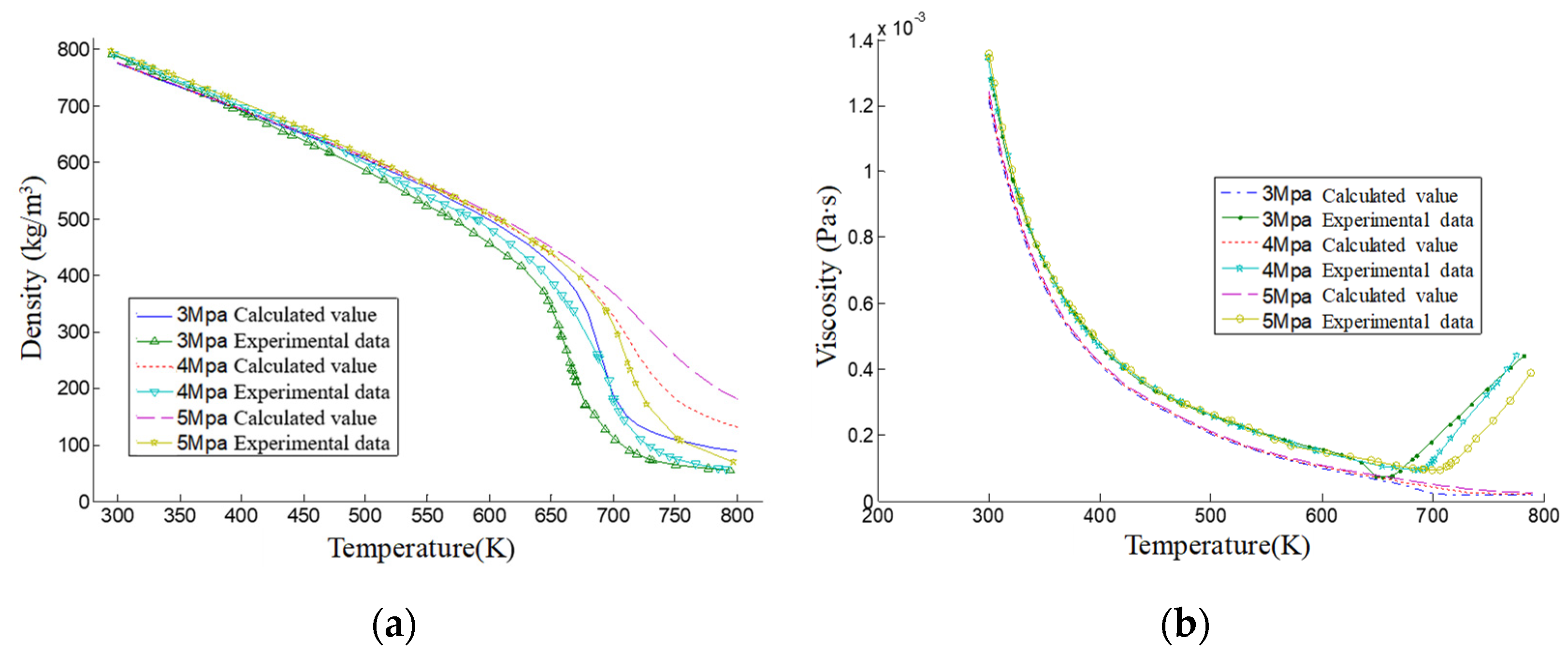
2.3. Material Properties

In this paper, a 10-component kerosene surrogate model [20] is adopted. The temperature range of kerosene in the cooling channel is 300~900 K, and the pressure varies from 3 MPa to 25 MPa. The SUPERTRAPP physical properties calculation software is used to calculate the density, viscosity, specific heat capacity, thermal conductivity and sound velocity of kerosene within the given temperature and pressure ranges. Take two physical properties as an example, Figure 3 presents the comparison of the physical properties computed by the 10-component kerosene surrogate model in this paper and published experimental results. Figure 3a shows a good comparison of the calculated density value of the kerosene surrogate model and the measured value from Deng et al. [21] under the operating pressure of 3 MPa, 4 MPa and 5 MPa and temperature from 295 K to 796 K for RP-3. Figure 3b illustrates the comparison of viscosity between calculated values and the experimental value from Deng et al. [22]. When the temperature exceeds 700 K, the difference in physical properties appears, because of the cracking and coking of kerosene at high temperatures. In general, the surrogate model can describe the properties of kerosene well with a temperature lower than 700 K.

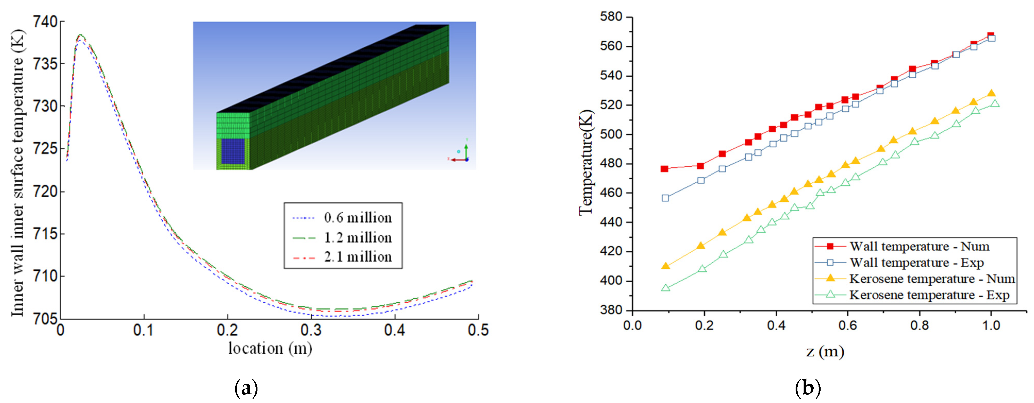
2.4. Numerical Scheme and Validation

With incompressible Boussinesq approximation, the physical process of flow and heat transfer of kerosene in the heating channel can be described by the following governing equations:
( ρ u j ) x j = 0  
( ρ u j u i ) x j = p x i + x j [ μ e f f ( u i x j + u j x i ) ]
T x i = x j [ λ ρ c p ( T x j + T x i ) ]
where u stands for the velocity, p for pressure, T for temperature, λ for the thermal conductivity, c p for the specific heat capacity and μ e f f for the effective viscosity. In this paper, the numerical simulation of the supercritical flow and heat transfer characteristics of kerosene with polymer in a rectangle channel is calculated by FLUENT, using the RNG k-ε turbulence mode with enhanced wall function. This model consists of two transport equations. One is kinetic energy equation (k) as shown in Equation (5):
t ( ρ k ) + x j ( ρ u i k ) = x j [ α k μ e f f k x j ] + G K + G b ρ ε Y M + S k  
In this equation G K = μ t ( μ i x j + μ j x i ) μ i x j , G b = β g i μ t P r t T x i and Y M = 2 ρ ε M t 2 , represent the turbulent flow energy generated by the average velocity gradient, the buoyancy, and the contribution of the fluctuating dilatation in compressible turbulence to the overall dissipation rate, respectively. In G b , β is the coefficient of heat expansion, M t = k / a 2 is the Mach Number and S k is the source term. a = γ R T is the speed of sound. The second equation is the kinetic energy dissipation equation, meant to calculate the energy dissipation rate (ε):
t ( ρ ε ) + x j ( ρ u i ε ) = x j [ α ε μ e f f ε x j ] + C 1 ε ε k ( G K + C 3 ε G b ) C 2 ε ρ ε 2 k R ε + S ε  
where μ eff = μ + μ t with μ t = ρ C μ k 2 ε . C 1 ε , C 2 ε , C 3 ε are constants and α k , α ε are the reciprocal of the Prandtl number of the turbulent kinetic energy k equation and the diffusion ε equation, respectively.   C μ = 0.0845 is constant and S ε is the source term.
In discretization, the second-order upwind difference scheme is applied to the convection term, the second-order center difference is used for the diffusion term, and the Semi-Implicit Method for Pressure-Linked Equations (SIMPLE) algorithm is used. The turbulence intensity and the hydraulic diameter are used to set the parameters of the turbulence. For other boundary conditions, velocity and pressure values are imposed at the computational domain’s inlet and outlet zones, respectively. The non-slip wall condition is applied to all the remaining wall surfaces of the channel.
As for the utilized grid, a structural-type grid is adopted, as shown in Figure 4, where the locally refined mesh was adopted. Three grids were selected for grid independence verification, namely 0.6 million, 1.2 million and 2.1 million, respectively. The three grids were simulated under similar conditions for verification. We take 300 K of the inlet temperature, 60 m/s of the inlet velocity, 30 MW/m2 of the heat flux of walls, and 20 MPa of the outlet pressure. Numerical simulation results in terms of the inner surface average temperature of the inner wall of the channel along the flow direction are shown in Figure 4. It is demonstrated that the difference in predicted wall temperatures is less than 1%. Therefore, the grid with 1.2 million cells satisfies the calculation accuracy.
To verify that the simulation scheme is suitable for the flow and heat transfer process of kerosene in the cooling channel. We chose an experiment by Zhu et al. [23] of the kerosene flow in a round pipe with heating of 151.75 kW/m2 as the validation. In the validation, the inlet temperature is 400 K; mass flux is 2 g/s; operating pressure is 5 MPa; the pipe has a diameter of 1.8 mm and length of 1000 mm. The comparison between calculation values and experimental data, in Figure 4b, can confirm the validity of the numerical method with the 10-component kerosene surrogate model.

3. Results

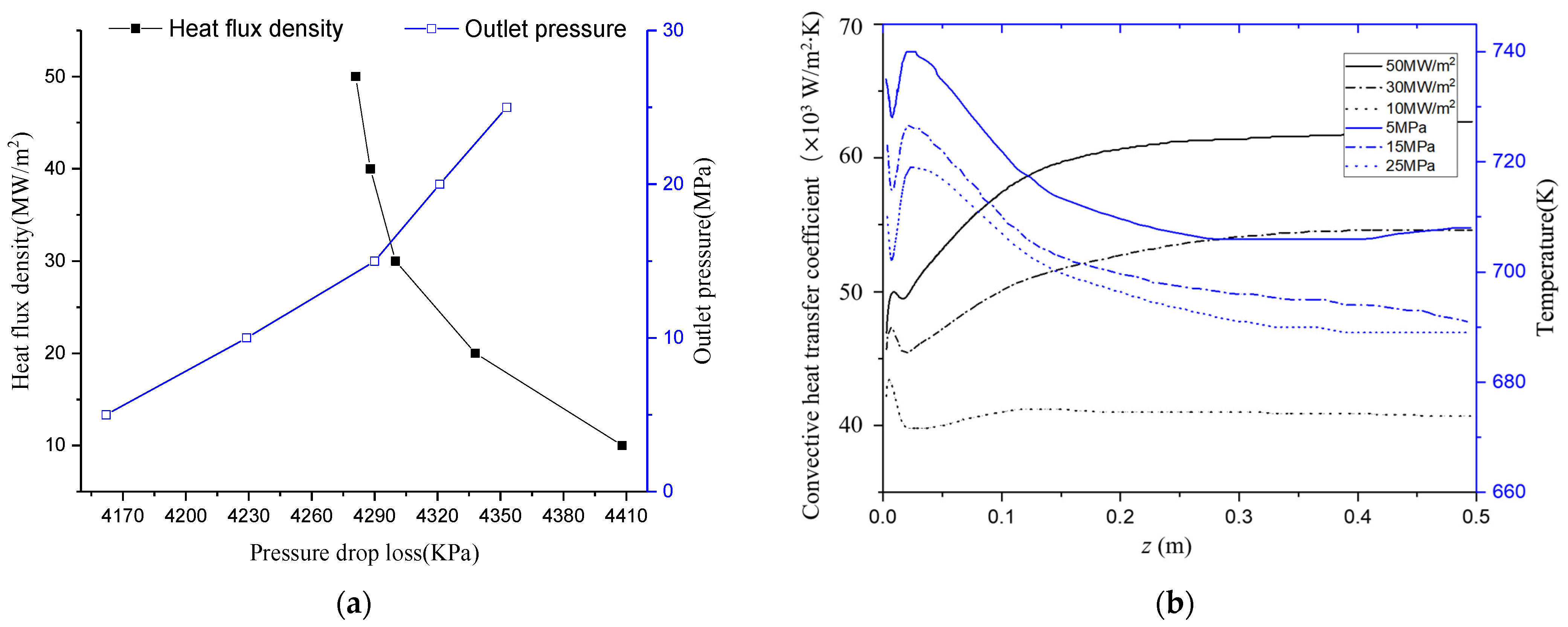
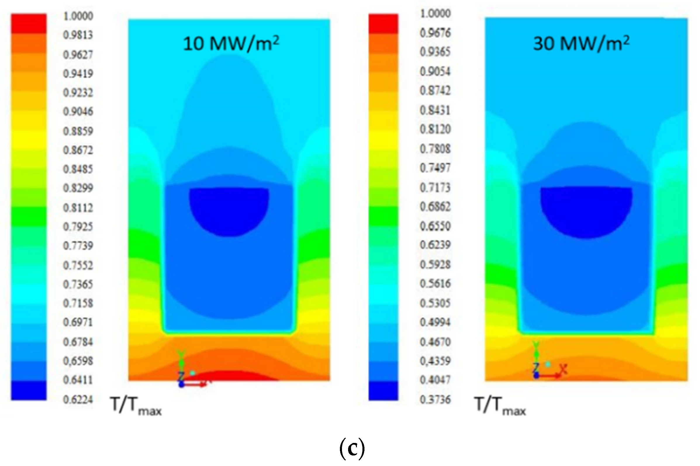
3.1. Pure Kerosene Flow in Rectangular Channel

Considering the regenerative cooling channel as the background. The wall heat flux density under five operating conditions was analyzed and its effect was investigated. As the heat flux density on the wall increase, the temperature of kerosene increases, the viscosity of kerosene inside the channel decreases, the velocity increases continuously, and the heat transfer performance becomes stronger. As shown in Figure 5a, it illustrates the pressure drop loss corresponding to different heat flux and different outlet pressure. The wall heat flux increases, the temperature of kerosene increases. With the increase in temperature of kerosene and decrease in working pressure, the decrease in viscosity and density reduce the pressure drop loss. The influence of pressure increase on heat transfer of kerosene flow is manifested in the increase in kerosene viscosity and density, which increases the critical temperature of kerosene and suppresses the turbulence development. It benefits to have working conditions with a temperature of kerosene lower than the critical temperature that derives a small fluctuation of physical properties. Figure 5b indicates that the convective heat transfer coefficient increases with the increase in heat flux, and the convective heat transfer coefficient has a significant bump near the inlet of the channel. The reason tells that the thermal boundary layer is very thin at the inlet, which is conducive to heat transfer, and the convective heat transfer coefficient suddenly increases. Along the flow direction, the thermal boundary layer gradually becomes thicker, the resistance of heat transfer increases, and the heat transfer efficiency decreases. Meanwhile, the temperature of kerosene gradually increases along the flow direction, the viscosity decreases, the velocity increases, and the turbulence intensity increases with high Re, which will increase the convective heat transfer coefficient. The working pressure of the combustion chamber of a liquid oxygen kerosene rocket engine is normally higher than 10 MPa, Figure 5b depicts that the inner surface temperature of the inner wall changes along the flow direction roughly the same. The magnitude of wall temperature at 5 MPa shows a significant offset to the other two cases because of its high critical temperature. Therefore, under ultra-high-pressure conditions, the heat transfer is better under high-pressure conditions. When the pressure is high, such as 15 MPa and 25 MPa, the physical property of kerosene has a slight change, which induces a little decrease in velocity. In Figure 5c, temperature distribution patterns are similar under different heat fluxes. The kerosene at different temperatures has different viscosities, which will promote velocity and temperature stratification. The temperature of kerosene near the top wall is lower than that in the center area of the channel, and the viscosity is larger than that in the center area. There is a velocity gradient in the wall and the center area itself. Due to the decrease in heat transfer caused by the change of velocity gradient and physical property, the temperature in the fluid domain of the cooling passage is divided into three layers, forming semi-circular radiation. Meanwhile, the channel structure, material and heating position make its semicircle radial distribution, which indicates that the increase in heat flux density enhances the heat transfer performance of the cooling channel.

3.2. Effects of the Polymer Additive

By comparing the flow behaviors and temperature characteristics of polymer kerosene solution and kerosene under different Reynolds numbers; the drag reduction rate and heat transfer reduction rate of polymer kerosene solution were analyzed. It should be noted that in the study of channel flow, the wall shear stress of a two-dimensional channel can be simplified to the τ w = H 2 L P . Where L is the length of the channel; P is the pressure difference, and H is the height. For the wall frictional resistance coefficient; the Fanning friction coefficient ( f = 2 τ w / ρ V 2 ) is used, where V is the inlet velocity.
Figure 6a compares the Fanning friction coefficient of kerosene and polymer kerosene solution under different Reynolds numbers, and the maximum of Fanning friction coefficient f = 0.58 R e 0.58 given by Virk’s Asymptote [24], which describes the drag reduction limit of the polymer additive under different Reynolds numbers. With the turbulence flow, the Fanning friction coefficient of the drag reduction solution is similar to the trend of Virk’s Asymptote. The curve offset of the Fanning friction coefficient of the polymer kerosene solution to that of the kerosene flow depicts the turbulent drag reduction.
The Fanning friction coefficient is used to measure the drag deceleration ratio ( DR = 100 ( f 0 f ) / f 0 ) ; where the Fanning friction coefficients for kerosene and flow and polymer solution are designated by f 0 and f , respectively. Figure 6b shows the deceleration rate (DR) of drag obtained by comparing results between polymer kerosene solution and pure kerosene. The rate of drag reduction increases rapidly with the flow rate increase. When the case of Re equals approximately 27,900, roughly reaching the maximum performance of the polymer additive, the growth of the drag reduction rate becomes flat with respect to high Reynolds numbers, and the maximum drag reduction rate is 46.8%. However, to describe the reduction in the convective heat transfer capacity of the turbulent drag reduction flow, we use the heat transfer reduction rate 100 ( N u 0 N u ) / N u 0 ) . N u 0 is the Nusselt number of kerosene, N u is the Nusselt number of the polymer kerosene solution. As the Reynolds number increases, the heat transfer reduction rate increases continuously, and the maximum heat transfer reduction rate reaches 37.5%. The addition of the polymer additive is disadvantageous for the heat transfer of the cooling channels.
Figure 7 illustrates dimensionless velocity distributions in the case of Re = 27,900. The corresponding sections of velocity profile of the pure kerosene flow conforms well to the velocity distribution of the viscous sublayer (U+ = y+, y+ < 5) and the logarithmic sublayer (U+ = 2.5lny+ + 5.5, y+ > 40), respectively. The velocity distribution of polymer kerosene is much lower than the limit one of Virk asymptote (U+ = 11.7lny+ − 17.0); the viscous sublayer of the polymer kerosene solution has a wider range of y+ than that of the pure kerosene. The addition of the polymer thickens the transition zone, and the entire velocity distribution has a larger magnitude at the core zone of the flow. It also weakens the fluid turbulence in the near wall region, and generates significant reductions of the velocity in the boundary layer, which weakens the momentum and heat transfer near the wall. Therefore, the heat transfer capacity is reduced with the turbulent drag reduction effect.

4. Conclusions

To reduce the energy loss of the cooling channel for high pressure refueling liquid oxy-kerosene rocket engine, this paper considers the turbulence drag reduction in the regenerative cooling technology using kerosene as the coolant. FLUENT with a compiled UDF is used to numerically analyze flow and heat transfer characteristics of the supercritical kerosene and the effect of polymer additives on these characteristics. The accuracy of the numerical calculation method is verified from the relative experiments.
By analyzing the influence of polymer additives on flow and heat transfer characteristics of the supercritical kerosene, the following important conclusions are obtained. The increase in inlet velocity causes a corresponding increase in heat transfer coefficient, but at the same time, there would be a larger pressure drop loss. Increasing the heat flux could enhance the heat transfer performance of the channel and reduces the pressure drop loss. Changes in the physical properties of kerosene under high-pressure conditions would lead to changes in the flow state and have a certain influence on the velocity, but the influence of working pressure changes is much less than that of heat flux and inlet velocity. Therefore, in contrast to the negligible influence of working pressure on the heat transfer, the inlet temperature, inlet velocity, and the heat flux on the channel wall are driving factors for flow and heat transfer characteristics of the supercritical kerosene. Again, in contrast to the flow and heat transfer condition in cases with pure kerosene, polymer additive play a crucial role in drag reduction. The maximum drag reduction ratio can reach 46.8%, but the maximum heat transfer reduction rate is also raised to 37.5%. Even though the pressure benefited using an additive can increase the thrust of the engine, the reduction in heat transfer is unfavorable for regenerative cooling.
In general, the 10-component kerosene surrogate can well describe the supercritical physical properties of kerosene. However, the calculated value at high temperatures and the actual physical property error increase due to the complex reaction of cracking and coking of kerosene. Therefore, it is necessary to consider further improvements of the surrogate model in future works.

Author Contributions

Conceptualization, B.L., Y.W. and W.C.; methodology, B.L., Y.W., M.T. and X.Z.; software, formal analysis, visualization, W.L., X.Z. and M.T.; validation, B.L. and W.C.; writing—original draft preparation, writing—review and editing, B.L., W.L., X.Z.; supervision, Y.W. and W.C. All authors have read and agreed to the published version of the manuscript.

Funding

This research was funded by the National Natural Science Foundation of China (Grant No. 51708151, 51576051, 51906037), the China Postdoctoral Science Foundation (Grant No.2019T120274), and the Fundamental Research Funds for the Central Universities (Grant No. HIT.NSRIF.2020049).

Data Availability Statement

The data presented in this study are available on request from the corresponding author.

Acknowledgments

This work has been supported financially by the National Natural Science Foundation of China (Grant No. 51708151, 51576051, 51906037), the China Postdoctoral Science Foundation (Grant No.2019T120274), and the Fundamental Research Funds for the Central Universities (Grant No. HIT.NSRIF.2020049), which is gratefully acknowledged by the authors. We are also grateful for the help provided by Xinyu Zhang, Alexis Muhirwa, and Deli Zhou to this work.

Conflicts of Interest

The authors declare no conflict of interest.

References

  1. Liu, Z.; Pan, H.; Feng, S.; Bi, Q. Dynamic behaviors of coking process during pyrolysis of China aviation kerosene RP-3. Appl. Therm. Eng. 2015, 91, 408–416. [Google Scholar] [CrossRef]
  2. Fu, Y.; Tao, Z.; Xu, G.; Deng, H.; Jia, Z. Experimental Study of Flow Distribution for Aviation Kerosene in Parallel Helical Tubes Under Supercritical Pressure. Appl. Ther. Eng. 2015, 90, 102–109. [Google Scholar] [CrossRef]
  3. Rashed, M.K.; Salleh, M.A.M.; Abdulbari, H.A.; Ismail, M.H.S. Enhancing the Drag Reduction Phenomenon within a Rotating Disk Apparatus Using Polymer-Surfactant Additives. Appl. Sci. 2016, 6, 355. [Google Scholar] [CrossRef] [Green Version]
  4. Paterson, R.W.; Abernathy, F.H. Turbulent flow drag reduction and degradation with dilute polymer solutions. J. Fluid Mechan. 1970, 43, 689–710. [Google Scholar] [CrossRef]
  5. Berman, N.S. Evidence for molecular interactions in drag reduction in turbulent pipe flows. Polymer Eng. Sci. 1980, 20, 451–455. [Google Scholar] [CrossRef]
  6. Dai, J.L.; Li, W.D.; Xa, X. Studies on the relationship between drag reduction and coil dimension of polymer reducer. Oilfield Chem. 1989, 6, 60–66. CNKI:SUN:YJHX.0.1989-01-009. (In Chinese) [Google Scholar]
  7. Brostow, W. Drag reduction and mechanical degradation in polymer solutions in flow. Polymers 1983, 24, 631–638. [Google Scholar] [CrossRef]
  8. Liaw, G.C.; Zakin, J.L.; Patterson, G.K. Effects of molecular characteristics of polymers on drag reduction. Aiche J. 1971, 17, 391–397. [Google Scholar] [CrossRef]
  9. Novelli, G.; Ferrari, L.A.; Vargas, G.G.; Loureiro, B.V. A synergistic analysis of drag reduction on binary polymer mixtures containing guar gum. Int. J. Biol. Macromol. 2019, 137, 1121–1129. [Google Scholar] [CrossRef]
  10. Wu, Y.G.; Zhao, X.D.; Liao, Q.D. The prediction and time-average velocity distribution of dilute polymer solutions drag reduction in pipe flow. J. Shanghai Instit. Mechan. Eng. 1987, 7, 4–8. (In Chinese) [Google Scholar]
  11. Cai, W.H.; Li, F.C.; Zhang, H.N. DNS study of decaying homogeneous isotropic turbulence with polymer additives. J. Fluid Mechan. 2010, 665, 334–356. [Google Scholar] [CrossRef]
  12. Li, C.F.; Xu, S.D.; Feng, X.D.; Wang, Y.H. Numerical simulation on heat transfer characteristics for turbulent drag-reducing flow with additives. Drain. Irrig. Machin. 2009, 27, 196–199. (In Chinese) [Google Scholar]
  13. Ebrahimi, A.; Naranjani, B.; Milani, S.; Javan, F.D. Laminar convective heat transfer of shear-thinning liquids in rectangular channels with longitudinal vortex generators. Chem. Eng. Sci. 2017, 173, 264–274. [Google Scholar] [CrossRef]
  14. Gong, K.; Cao, Y.; Feng, Y.; Zhang, Y.; Qin, J. Flow and Mass Transfer of Pyrolytic Aviation Kerosene in Curved Channel. J. Thermophys. Heat Transf. 2021, 35, 53–62. [Google Scholar] [CrossRef]
  15. Edwards, T.; Maurice, L.Q. Surrogate Mixtures to Represent Complex Aviation and Rocket Fuels. J. Propuls. Power 2001, 17, 461–466. [Google Scholar] [CrossRef]
  16. Bruno, T.J.; Huber, M.L. Evaluation of the Physicochemical Authenticity of Aviation Kerosene Surrogate Mixtures. Part 2: Analysis and Prediction of Thermophysical Properties. Energy Fuels 2010, 24, 4266–4276. [Google Scholar] [CrossRef]
  17. Zhang, Y.J.; Zhong, F.Q.; Xing, Y.F.; Zhang, X.Y. Numerical study on turbulent flow and convection heat transfer in right-angle elbow of supercritical kerosene. In Proceedings of the Chinese Congress of Theoretical and Applied Mechanics-2015 Proceeding, Chengdu, China, 25–27 December 2015. (In Chinese). [Google Scholar]
  18. Bird, R.B. Useful Non-Newtonian Models. Annu. Rev. Fluid Mech. 1976, 8, 13–34. [Google Scholar] [CrossRef]
  19. Jia, Z.X.; Xu, G.Q.; Deng, H.W.; Wen, J. Dynamic viscosity measurements of aviation hydrocarbon fuel RP-3 at sub-critical pressures. J. Beijing Univ. Aeronaut. Astronaut. 2014, 40, 934–938. (In Chinese) [Google Scholar]
  20. Zhong, F.; Fan, X.; Yu, G.; Li, J.; Sung, C.-J. Heat Transfer of Aviation Kerosene at Supercritical Conditions. J. Thermophys. Heat Transf. 2009, 23, 543–550. [Google Scholar] [CrossRef] [Green Version]
  21. Deng, H.W.; Zhang, C.B.; Xu, G.Q.; Tao, Z.; Liu, G.Z. Density Measurements of Endothermic Hydrocarbon Fuel at Sub- and Supercritical Conditions. J. Chem. Eng. Data 2011, 56, 2980–2986. [Google Scholar] [CrossRef]
  22. Deng, H.W.; Zhang, C.B.; Xu, G.Q.; Zhang, B.; Tao, Z.; Zhu, K. Viscosity Measurements of Endothermic Hydrocarbon Fuel from (298 to 788) K under Supercritical Pressure Conditions. J. Chem. Eng. Data 2012, 57, 358–365. [Google Scholar] [CrossRef]
  23. Zhu, J.; Tao, Z.; Deng, H.; Wang, K.; Yu, X. Numerical investigation of heat transfer characteristics and flow resistance of kerosene RP-3 under supercritical pressure. Int. J. Heat Mass Transf. 2015, 91, 330–341. [Google Scholar] [CrossRef]
  24. Virk, P.S. Drag reduction fundamentals. Aiche J. 1975, 21, 625–656. [Google Scholar] [CrossRef]
Figure 1. Schematic diagram of the cooling channel and the physical picture.
Energies 14 06758 g001
Figure 2. The effect of the shear ratio on the kinematic viscosity for the JZM polymer additive.
Energies 14 06758 g002
Figure 3. Comparisons of calculated values and experimental data (a) density under different pressure conditions (b) viscosity under different pressure conditions, with different temperatures of kerosene.
Energies 14 06758 g003
Figure 4. (a) Grid independence and (b) validation by kerosene flow in a heating pipe.
Energies 14 06758 g004
Figure 5. Effects of heat flux density on (a) pressure drop loss, (b) convective heat transfer coefficient at the center line, and (c) contours of normalized temperature at z = 250 mm.
Energies 14 06758 g005aEnergies 14 06758 g005b
Figure 6. Influence on flow and heat transfer versus different Reynolds numbers, by the addition of polymer additive (a) Fanning friction coefficient, (b) heat transfer reduction rate and deceleration rate.
Energies 14 06758 g006
Figure 7. Dimensionless velocity distribution with wall distance for different flow boundary layers.
Energies 14 06758 g007
Publisher’s Note: MDPI stays neutral with regard to jurisdictional claims in published maps and institutional affiliations.

