Article

Numerical Investigation of Microchannel Heat Sink with Trefoil Shape Ribs

1
Department of Mechanical Engineering, University of Engineering & Technology, Peshawar 25120, Pakistan
2
Department of Mechanical Engineering, Aerospace and Aviation Campus, Air University Islamabad, Kamra 43570, Pakistan
3
Department of Mechanical Engineering, CECOS University of Information Technology and Emerging Sciences, Peshawar 25000, Pakistan
4
School of Engineering, Edith Cowan University, Joondalup, WA 6027, Australia
5
School of Mechanical and Design Engineering, University of Portsmouth, Portsmouth PO1 3DJ, UK
6
Department of Automated Mechanical Engineering, South Ural State University, Lenin Prosp. 76, 454080 Chelyabinsk, Russia
*
Authors to whom correspondence should be addressed.
Energies 2021, 14(20), 6764; https://doi.org/10.3390/en14206764
Submission received: 9 September 2021 / Revised: 4 October 2021 / Accepted: 14 October 2021 / Published: 17 October 2021
(This article belongs to the Special Issue Computational Heat Transfer and Fluid Mechanics)

Abstract

:
The present study investigates the thermo-hydraulic characteristics of a microchannel sink with novel trefoil Shaped ribs. The motivation for this form of rib shape is taken from the design of lung alveoli that exchange oxygen and carbon dioxide. This study has been conducted numerically by using a code from the commercially available Fluent software. The trefoil shaped ribs were mounted on the centerline of different walls of the microchannel in three different configurations. These consisted of base wall trefoil ribs (MC-BWTR), sidewall trefoil ribs (MC-SWTR), all wall trefoil ribs (MC-AWTR) and smooth channel (MC-SC) having no ribs on its wall. The streamline distance between the ribs was kept constant at 0.4 mm, and the results were compared by using pressure drop (∆p), Nusselt number (Nu), thermal resistance (Rth) and thermal enhancement factor (η). The results indicated that the addition of trefoil ribs to any wall improved heat transfer characteristics at the expense of an increase in the friction factor. The trends of the pressure drop and heat transfer coefficient were the same, which indicated higher values for MC-AWTR followed by MC-SWTR and a lower value for MC-BWTR. In order to compare the thermal and hydraulic performance of all the configurations simultaneously, the overall performance was quantified in terms of the thermal enhancement factor, which was higher than one in each case, except for MC-AWTR, in 100 < Re < 200 regimes. The thermal enhancement factor in the ribbed channel was the highest for MC-SWTR followed by MC-BWTR, and it was the lowest for MC-AWTR. Moreover, the thermal enhancement factor increases with the Reynolds number (Re) for each case. This confirms that the increment in the Nusselt number with velocity is more significant than the pressure drop. The highest thermal enhancement factor of 1.6 was attained for MC-SWTR at Re = 1000, and the lowest value of 0.87 was achieved for MC-AWTR at Re = 100.

1. Introduction

The increasing demand for digitalization has shifted the trend of the modern world towards the miniaturization of electronic equipment where hundreds of thousands of transistors are installed on a single silicon chip. Due to the reduction in the sizes of these equipment, the power density increased rapidly and can be as high as up to 1 W/mm2. However, great care is needed to maintain such equipment for its safety and improved life cycle. Therefore, modern techniques including cooling using liquid such as a micro-jet, heat pipe, spray impingement and microchannel cooling are introduced to fulfill the requirement of higher heat dissipation [1]. Over time, the cooling techniques have been improved from cooling by force convection and air to more advanced techniques.
The microchannel cooling system was first coined in 1981 by Tuckerman and Pease [2]. Microchannel cooling is a passive technique for dissipating heat from electronic devices without occupying a larger space than other dissipating setups. A microchannel heat sink (MCHS) with smooth geometry is used to dissipate heat from different devices. The usage and capacity of microelectronic equipment increased drastically; as a result, an increased amount of heat is produced inside this equipment. To dissipate this large amount of heat, a smooth MCHS will be unable for that much dissipation. Therefore, the thermal performance of smooth MCHS needs improvement. The thermal performance of MCHS can be improved by performing some modifications to the smooth one and then some thermal performance parameters such as thermal enhancement factor (η), friction factor (f) and Nusselt number (Nu) will be compared with a smooth channel after modification (adding some extended surfaces or cavities) to the channel. In most cases, the better thermal performance of MCHS is associated with irreversibility in the flow field, which is computed in terms of friction factor (f), entropy generation (Sgen) and thermal resistance (Rth). The main objective of many researchers is to increase the heat dissipation rate (Nusselt number (Nu)) with minimal pressure loss [3,4,5,6].
Many researchers worked on the effect of extended surfaces (fins or ribs) on the performance improvement of MCHS. For example, Rehman et al. [7] added dimple shaped ribs to the smooth channel for enhancement in the overall performance of the smooth channel. In their study, different cases were used, which included base wall ribs, sidewall ribs and all walls’ ribs. Moreover, aligned, staggered and mixed configurations of each case were investigated numerically. Their results concluded that the case in which all walls were ribbed had better overall performance for each configuration. The worst performance was noted for the case in which ribs were added to the sidewall. Similarly, numerical studies and comparisons of heat transfer, friction factor and thermal enhancement factor of six different micro-channels were carried out by Zhu et al. [8], and they intended to report the best one. The study compared smooth rectangular micro-channel, side grooved rectangular micro-channel, side grooved with diamond shape ribs, side grooved with rectangular shape ribs, side grooved with elliptic shape ribs and side grooved with forwarding triangular shape ribs micro-channel. The results concluded that the combination of grooves and ribs has better performance than simple ribbed micro-channel. The side grooved with rectangular shape ribs micro-channel has the best overall performance at Re = 500, relative rib width = 0.25 mm and minimum rib-groove distance = 0.1 mm.
Xiao et al. [9] worked on the thermal improvement of micro-channel by producing turbulence in a flow field with the help of V-shape ribs. A significant enhancement in the overall performance of micro-channel has been noted from this numerical study. Similarly, Hassani et al. [10] conducted a numerical and experimental study to investigate the enhancement in the overall performance of MCHS by adding pins and chamber shape cavity to it. In their study, four different cases were used, which included smooth micro-channel, smooth micro-channel with pins, smooth micro-channel with chamber shape cavity and smooth micro-channel with pins and chamber shape cavity. Their results concluded that the addition of pins improved heat transfer by 44.8% and chamber shape cavity by 3.7%, while the simultaneous addition of pins and cavity improved heat transfer by 37.5%. The highest enhancement factor was noted for the pin located at the middle of the cavity. Furthermore, Ahmad et al. [11] used cylindrical shape ribs and cavities to numerically investigate the performance enhancement in MCHS with different cases. In this study, a base wall with cylindrical shape ribs, a sidewall with cylindrical shape ribs and all walls with cylindrical shape ribs were compared. Moreover, the effects of rib spacing for all wall ribs cases and comparisons of all wall ribs, all wall cavities and the combination of both were also taken into account in this study. It was concluded that the case of all wall ribs performed best among all cases, based on entropy generation, thermal enhancement factor, thermal resistance and transport efficiency.
Yang et al. [12] proposed three different pin fin cross sections attached to micro-channel heat sinks to improve heat dissipation capacity. These cross-sections include rhombus, hydrofoil and sinusoidal shapes. Their experimental and numerical results concluded that the performance of the sinusoidal cross section performed best among the three cases compared. Similarly, Naqiuddin et al. [13] studied the effects of structure parameters on rectangular micro-channel and found that for any structure, the performance in terms of heat transfer increases at the cost of higher pressure drop. The average temperature of the channel was reduced by 33 K with an increase of 1000 kPa pressure drop. The optimum performance was noted for the coolant’s flow rate of less than 200 mL/min. Similarly, Wang et al. [14] carried a numerical study of rectangular micro-channel with sidewall truncated ribs. Three different ribs parameters, including truncation gap height, width and ribs arrangement, were used to study the improvement in the hydro-thermal behavior of MCHS in flow regimes of 100 < Re < 1000. Their study confirmed that the results of truncated ribs are far better than their counterpart traditional ribs; the parallel arrangement results in a higher overall heat transfer coefficient.
Chuan et al. [15] used porous ribs instead of solid ribs with a straight channel to assess the performance of the micro-channel. They examined that, with porous ribs, the increment in pressure drop is lower than compared to solid ribs of exact dimensions. Moreover, the same porous rib increased the thermal resistance at the same time. Similarly, Wang et al. [16] proposed a multi-objective genetic optimization technique for the optimal design of MCHS. In their study, double-layered MCHS with semi-porous ribs was considered. It was concluded that the decrement in thermal resistance is linked with an increment in pumping power. For an optimum design, pumping power is reduced by 16.40% and thermal resistance by 14.06% compared to the reference design. Furthermore, Ahmad et al. [17] proposed four different novel shapes of ribs attached to the sidewall of rectangular microchannel heat sinks, including trapezoidal, rectangular, elliptical and hydrofoil shapes for the improvement of the hydro-thermal performance of MCHS. The results revealed that each case improved overall heat transfer performance. Moreover, elliptical ribs have better thermal performance; however, the hydrofoil file has better performance in terms of friction factor and pressure loss.
Keeping in view the above literature, it is very obvious that the addition of each type of ribs enhances heat transfer with an increase in pumping power. Considerable research has been performed on traditional shapes of ribs; however, no significant work was found on unique shape ribs. In this study, bio-inspired rib shape (trefoil) is used where ribs are added in three different wall configurations consisting of ribs added to the base wall (BWTR), Sidewall (SWTR) and (AWTR). The addition of trefoil shape ribs is expected to significantly improve the overall performance of MCHS. The novelty of this work is due to the unique bio-inspired shape of ribs, and the motivation is basically taken from the lungs of humans; the lung’s internal structure consists of trefoils such as shape alveoli which are involved in the exchange of oxygen and carbon dioxide.
The present study aims to investigate the performance of MCHS numerically with novel trefoil ribs using ANSYS Fluent. This study aims to analyze the performance of MCHS by employing a novel shaped rib at different walls. The proposed models of novel ribs include trefoil shape ribs. The use of trefoil rib is the special novelty of this study, and it has not been investigated in the past literature. In most of the previous papers, the ribs were mounted on the sidewalls of MCHS in the transverse configuration. However, in this study, the ribs were mounted in the centerline configuration and mounted on different walls, i.e., base wall, sidewall and all walls. This study assesses the performance of MCHS with trefoil shape ribs by using numerical simulation in a laminar flow regime with Reynolds number (Re) in the range of 10–1000. Moreover, the performance of the base wall with trefoil ribs (BWTR), sidewall with trefoil ribs (SWTR) and all walls with trefoil ribs (AWTR) was compared with each other and with smooth micro-channel based on thermal resistance, pressure drop, friction factor ratio, heat transfer coefficient, Nusselt number ratio and thermal enhancement factor.

2. Materials and Methods

In the present study, the micro-channel is made of copper, and water is used as a coolant. Numerical simulations of the microchannel (3D) using CFD techniques (RANS Simulations) are analyzed. During numerical simulations, the smooth micro-channel and micro-channel with trefoil shape ribs attached to the centerline of base, side and to all walls with a streamline distance of 0.4 mm were modelled. The model was meshed and imported to CFD Fluent in order to calculate Δ p , h, f / f o , N u / N u 0   , Rth and η with the addition of trefoil shape ribs. The details of the material used and methodology adopted for the present study are given in the following section respectfully.

2.1. Geometrical Shape of MCHS

In the present study, a rectangular microchannel is used because of its superior thermal performance among circular, hexagonal, rectangular and triangular cross-sections [18]. Ribs in the trefoil shape are attached to the base wall, sidewall and all walls with a stream-wise distance (pitch) of 0.4 mm; the computational domain of each case and geometric details of the trefoil rib are shown in Figure 1. Moreover, the thermophysical properties of both the fluid (water) and solid (copper) domains are kept constant and are given in Table 1.

2.2. Governing Equations

The fluid is a Newtonian fluid with constant thermophysical properties, and the flow is laminar, steady-state and incompressible. Moreover, the effects of radiation and body forces are negligible and can be neglected. With all these assumptions, the governing equations for solid as well as a fluid domain can be presented as follows:
Continuity equation for fluid:
u x + v y + w z = 0
where u , v and w are the velocity component of fluid in the x , y and z directions, respectfully. The movement equations in x-direction, y-direction and z-direction are written as stated below:
u u x + v u y + w u z = 1 ρ f p x + μ f ρ f ( 2 u x 2 + 2 u y 2 + 2 u z 2 )
u v x + v v y + w v z = 1 ρ f p y + μ f ρ f ( 2 v x 2 + 2 v y 2 + 2 v z 2 )
u w x + v w y + w w z = 1 ρ f p z + μ f ρ f ( 2 w x 2 + 2 w y 2 + 2 w z 2 )
where ρ f represents the density, and μ f is the dynamic viscosity of the working fluid.
The energy equation for fluid and solid domains can be written as follows:
u T f x + v T f y + w T f z = k f ρ f C P f ( 2 T f x 2 + 2 T f y 2 + 2 T f z 2 )
k s ( 2 T s x 2 + 2 T s y 2 + 2 T s z 2 ) = 0
where T f   is the fluid temperature, k f is the thermal conductivity and C P f is the specific heat of the working fluid.   T s is the temperature, and k s is the thermal conductivity of the solid domain.
The following boundary conditions were used to solve the above equations.
At the inlet of the channel where x = 0 mm, the velocity-inlet boundary conditions with a fluid inlet temperature of 293.15 K are assumed to be as follows.
u = u i n  
T f = T i n
The different values for u i n are calculated by using an Re number in the range of 100 to 1000.
At the outlet of the channel, where x = 10 mm, we have the following.
p = p o u t = 1   a t m
At the bottom surface, the uniform heat flux is given by the following.
q = 100 w c m 2
At inner wall of the channel, no slip boundary conditions are applied as follows.
u = v = w = 0
k s T s n = k f T f n
At all the remaining walls, the adiabatic conditions are used as follows.
T s y = T s z = 0

2.3. Numerical Method and Mesh Independence

ANSYS Fluent is utilized for the numerical solution in the present study. The second-order difference schemes for discretization of diffusion terms and second-order upwind schemes for convection term are used in the present case. The convergence criteria of 10−6 are used for all variables. Different mesh sizes for the MC-BWT case for Re = 500 are solved, and the relative error in Δ p and Nu is calculated to check the reliability of the solution and summarized in Table 2:
e % = P 2 P 1 P 1 100
where P1 is the value of any parameter with the smallest mesh size, and P2 is the value with other mesh sizes.
As shown in Table 2, for Mesh No. 3, the relative error in pressure was less than 0.2%, and the relative error in Nu was less than 0.5%; thus, this mesh, with 811,646 number of elements, was used for analysis in the present study.

2.4. Data Reduction

In MCHS, the η is used for performance measurement of different micro-channels; it is a function of both ratios of N u and f and is given by the following equation [19].
η = ( N u N u 0 ) ( f f 0 ) 1 3
In this equation, f   is the Darcy friction factor [20], and N u is the Nusselt number given by the following:
f = 2 D h Δ p L c h ρ f u m 2
N u = h a v g D h k f
where D h is the hydraulic diameter,   Δ p   is the pressure drop, L c h is the length of the channel and h a v g is the average heat transfer coefficient and can be calculated by following relationships:
D h = 2 H c h W c h H c h + W c h
h a v g = q w A b a s e 2 ( W c h + H c h ) L c h Δ T
where H c h is the height, W c h is the width of the channel, q w is the heat flux and A b a s e is the area of the base wall. Δ T is the temperature difference between channel wall temperature ( T w ) and fluid mean temperature ( T f ), and they are given by the following.
Δ T = T w T f
T w = T w x , y d y d x d y d x
T b = T b x , y d y d x d y d x
T f = T f i , x ρ f i , x   | v . d A | d x ρ f i , x   | v . d A | d x
The overall thermal resistance is given as follows.
R t o t = R c o n d + R c o n v + R c a p  
R t o t = T b T c h q w A b + T c h T f q w A b + T f T i n q w A b = T b T i n q w A b

3. Results

The accuracy of numerical schemes used for the present study is first validated with available experimental work in literature. The validated numerical modal is then used for calculating the Δ p , h, f / f o , N u / N u 0 , Rth and η for MC-BWTR, MC-SWTR and MC-AWTR. The calculated values for ribbed channels are compared with the reference case (MC-SC), which are discussed in detail in the following sections.

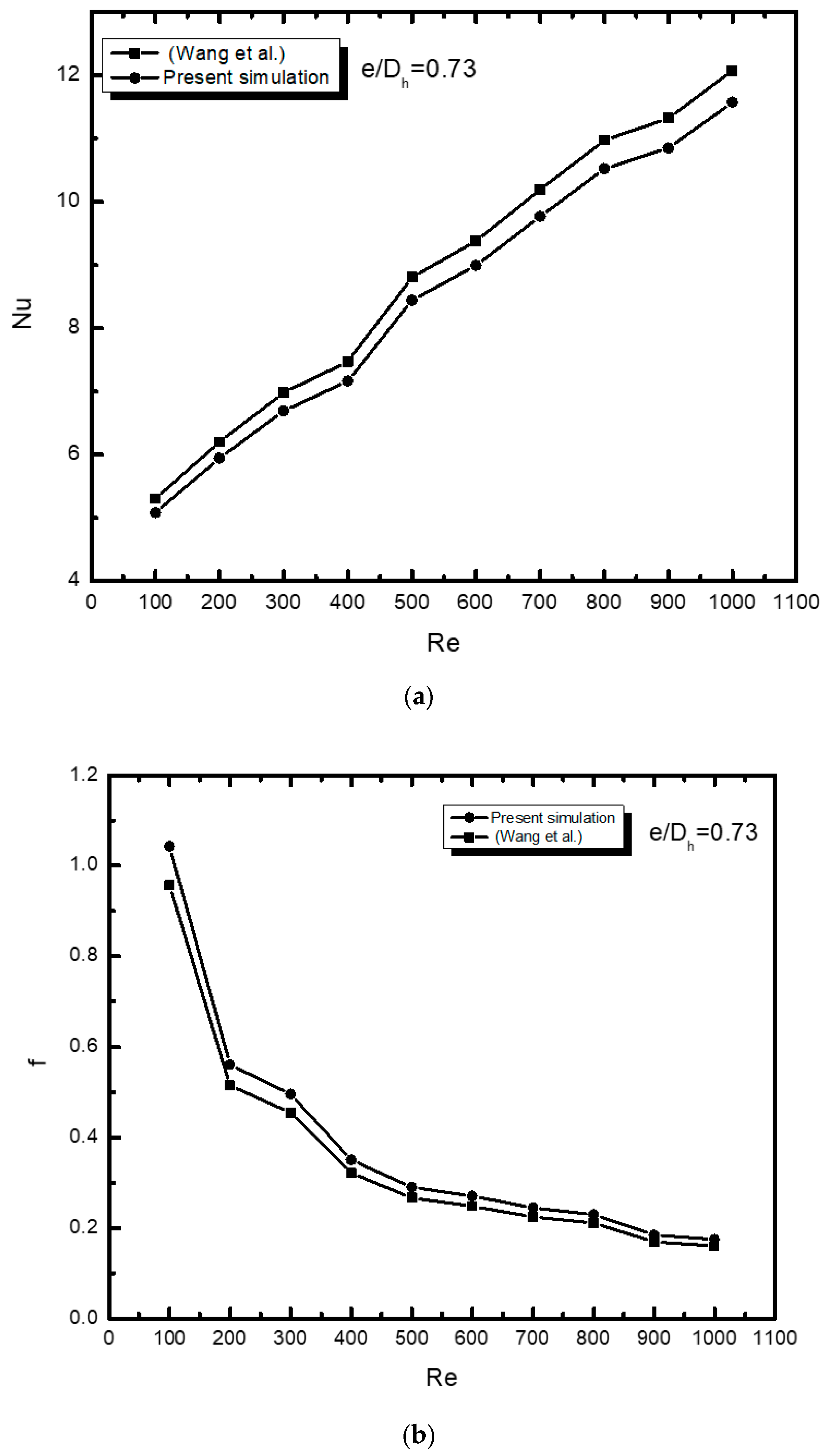
3.1. Model Validation

As shown in Figure 2, the Nu and f values were calculated and compared to the experimental work of Wang et al. [21] with the uniform inlet velocity, Tin = 293 K, which is calculated from Re and a heat flux of 100 W/cm2 with the same conditions as used in the experimental study [21]. The obtained results were close to the experimental results available in the literature with less than 5% deviation; hence, the present model can be used for calculating the thermal-hydraulic perimeters of MCHS.

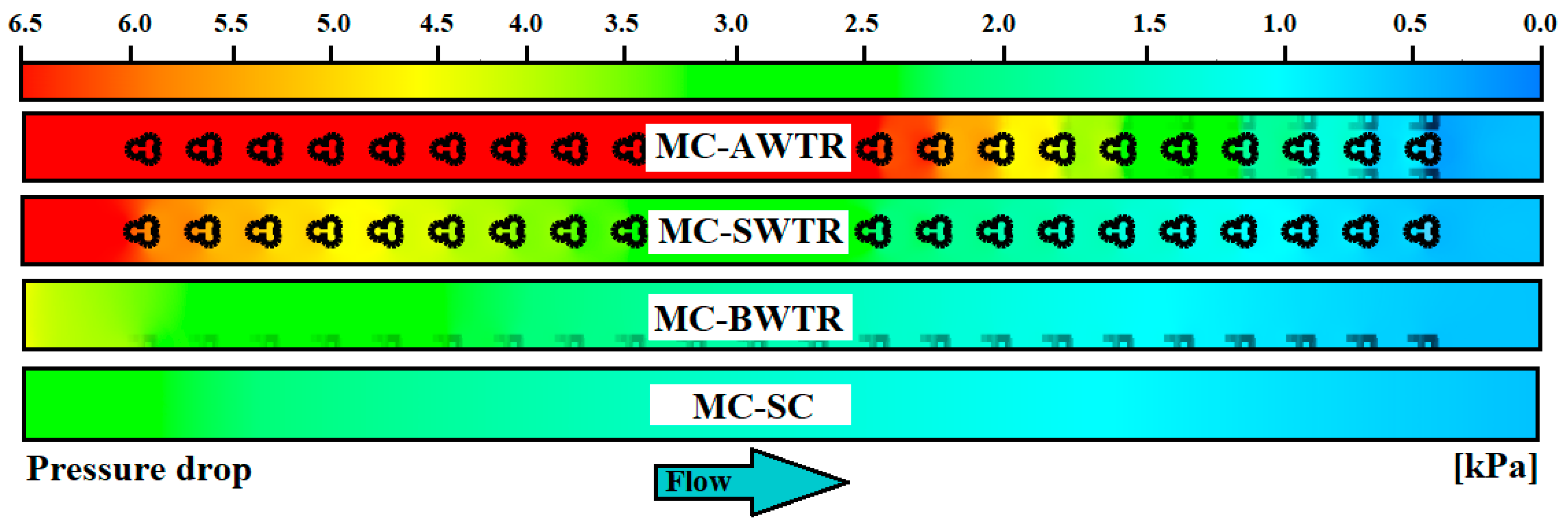
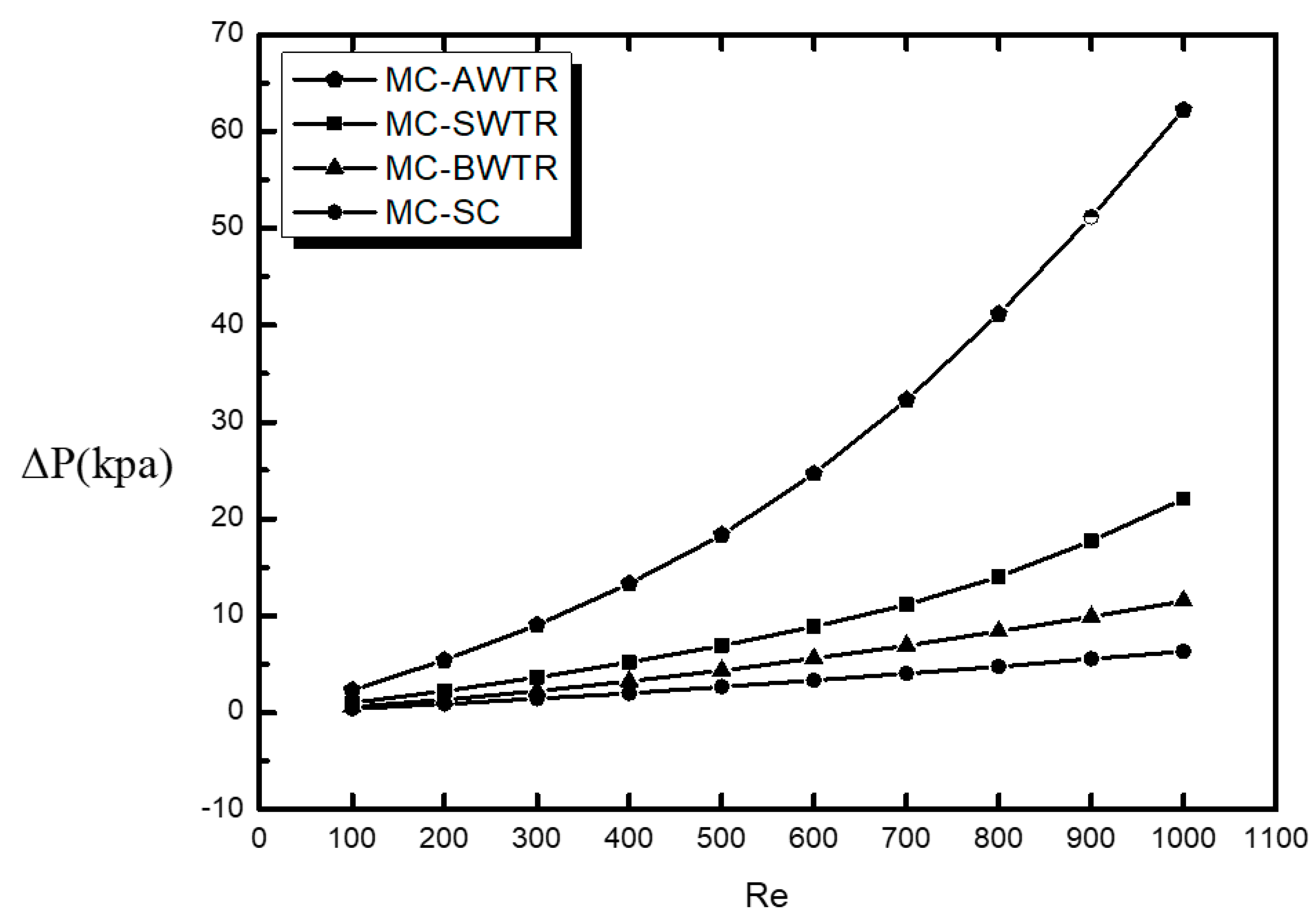
3.2. Characteristics of Temperature and Pressure Distribution

The temperature distribution for MCHS with trefoil shaped ribs was added to the base wall (BWTR), sidewall (SWTR) and all wall (AWTR) cases together with the smooth channel, which is shown in Figure 3. This was performed in order to study the temperature distribution (cooling) with the addition of trefoil shape ribs. MC-AWTR case showed better cooling in terms of temperature drop followed by MC-SWTR and MC-BWTR, respectively.
The increase in thermal performance was at the cost of an increase in power required to pump the same amount of fluid because the ribs blocked the flow and increased the pressure requirement. The pressure distribution was the determining factor for pumping power; the pressure distributions of all ribbed cases along with smooth channel are presented in Figure 4. The pressure drop in the smooth channel was due to the friction of the wall, while for the ribbed channel, it was the combined effect of wall roughness and resistance offered to the flow by ribs. The pressure drop of MC-SC is minimum, and the pressure drop for MC-AWTR is highest because of the presence of a higher number of ribs.
The temperature distribution (cooling diagram) recommended the MC-AWTR case, while the pressure distribution recommended MC-BWTR. Other performance parameters can be analyzed for final conclusions.

3.3. Performance Comparison

Performance measurement of all cases was carried out for Re = 100–1000 with a step of 100, and the results are presented in contrasting graphs to indicate the improvements made by the trefoil shaped ribs. In addition to the performance improvements in the different cases and the reference case, MC-SCs were compared by plotting Δ p , h, f / f o , N u / N u 0 , Rth and η.
The Δ p of the MCHS with trefoil shaped ribs and a straight channel are displayed in Figure 5. The lowest Δ p was attained in the MC-SC case, which was only produced by the wall’s roughness. The Δ p in the ribbed channel cases, MC-BWTR, MC-SWTR and MC-AWTR, was a combination of Δ p by the wall’s roughness and Δ p produced by the blockage offered by ribs. The Δ p for the MC-BWTR case was minimal compared with the other ribbed cases, and this was due to the ribs being attached to only one wall. However, in the MC-SWTR and MC-AWTR cases, the ribs were attached to either two or four walls, respectively. In the MC-SWTR case, the ribs were attached to two walls; therefore, the number of ribs, in this case, was higher than for MC-BWTR. As such, the Δ p was more than the MC-SC and MC-BWTR cases. A maximum Δ p was noted for the MC-AWTR case because each wall contained ribs and blocked the flow, thereby causing the Δ p to rise. At Re < 250, the Δ p for MC-SC, MC-BWTR and MC-SWTR was almost the same, whereas the MC-AWTR case displayed higher Δ p . Moreover, in the range of 100 < Re < 600, the MC-BWTR Δ p was almost equal to MC-SC compared to Δ p in the other cases, which was significantly higher. The pressure drop increases with an increase in Re for all cases; however, this increase is minimal in the low Re range, while the increase is maximal in the higher Re range, i.e., Re > 500. Moreover, the pressure drop behaviour against Re of MC-AWTR is stiffer when compared to other ribbed cases such as MC-SWTR and MC-BWTR, which is flattened and indicates that the increase in Δ p for MC-AWTR case is higher than MC-SWTR and MC-BWTR.
Figure 6 shows the comparison of h for the various MCHSs together with the MC-SC. It is clear that the h value in all ribbed cases was significantly higher than for the MC-SC. The addition of trefoil shaped ribs caused better mixing and produced higher h values as a result. The heat transfer coefficient for the MC-AWTR case was highest, and it was the lowest for MC-BWTR. This could be because the number of ribs in MC-AWTR is greater than that of MC-BWTR, which provides more heat transfer area and better mixing of fluid. Moreover, the MC-SWTR case had better performance in terms of heat transfer than the MC-SC and MC-BWTR cases. The increase in h at Re < 200 from MC-SC to the ribbed channel was smaller; however, at Re > 200, the increase was significantly higher because the turbulence was higher at Re, which caused high heat transfer. Furthermore, h increases with an increase in Re. The highest increase is noted for each case compared to the straight channel (MC-SC) at Re = 1000, which is 3, 2.4 and 1.7 times for MC-AWTR, MC-SWTR and MC-BWTR, respectively.
The friction caused by the addition of ribs to the base wall, sidewalls and all walls resulted in an increase in friction factor. The reltive increase in friction factor with trefoil shaped ribs was calculated in terms of friction factor ratio ( f / f o ) and plotted against Re, as shown in Figure 7. It is clear that the f / f o for MC-BWTR and MC-SWTR was considerably smaller than the ratio for MC-AWTR. The f / f o   at Re = 1000 for MC-AWTR and MC-SWTR is 1.9 and 5.39 times higher when compared to MC-BWTR, respectively, because the friction factor is the measure of the resistance to flow, which is at the maximum in the case of the low flow area of MC-AWTR. The f / f o ratio rose with the increase in Re, while an increase in the SC-BWTR case was almost negligible, as indicated by the flatness of the curve. This was because very few turbulence enhancers were present at the base wall. The increase in the f / f o for MC-SWTR with an increase in the Re was insignificant up to Re < 700 regimes; however, the increase was significant above Re > 700 regimes for the MC-AWTR case. The f / f o rose with the increase in Re number throughout due to the presence of ribs at all walls.
Figure 8 shows the comparison of the Nu for various MCHSs along with the MC-SC. The Nu is a dimensionless number used to indicate the capability of heat transfer by a channel. The higher the Nu number, the more effective heat transfer will be. Figure 8 indicates that the minimum value of Nu was observed for MC-SC, while the maximum value was noted for MC-AWTR. Conversely, MC-BWTR had a smaller Nu than MC-SWTR and MC-AWTR. The average percentage increase in Nu is 142%, 90% and 51% for MC-AWTR, MC-SWTR and MC-BWTR, respectively, when compared to MC-SC. The Nu was directly proportional to the effective heat transfer area, which was maximum for MC-AWTR and minimum for MC-SC. The effective heat transfer area for MC-SWTR was higher than MC-BWTR, and this explained why MC-SWTR performed better in terms of Nu than MC-BWTR. Moreover, Nu inclined linearly with Re for all cases except MC-SWTR after Re > 600. This was because the ribs were attached to both sides in MC-SWTR, which produced turbulence compared to other cases at higher velocity.
In order to compare the effectiveness of the heat transfer among ribbed channels, the N u / N u 0   of the ribbed channel and the MC-SC was plotted against the Re, and the results are presented in Figure 9. It is evident that MC-AWTR performed exceptionally well in comparison to the MC-SC in terms of Nu; the performance of MC-AWTR was three times superior to MC-SC at Re = 1000. MC-BWTR had a slight increase in Nu compared to MC-SC: the maximum value of N u / N u 0 is 1.5 at Re = 1000, half of the MC-AWTR at the same Re. MC-SWTR performance in terms of Nu ratio was better than MC-BWTR and slightly lower than MC-AWTR; therefore, this case’s performance was 2.5 times higher than the MC-SC at Re = 1000. The value of N u / N u 0 increased smoothly with Reynolds number except for MC-SWTR in Re > 600. The increase in the value of N u / N u 0 was higher with Re and MC-BWTR in Re < 200, where the curve was nearly flat, representing a minor increase in N u / N u 0 with Re.
MCHS performed better thermally with the addition of ribs to any wall; however, the addition of ribs declined the hydrodynamic performance by increasing pressure drop, which was not required. As a result, there should be a trade-off between thermal improvement and pressure drop, which could be calculated in terms of overall η. The η for trefoil shaped ribs of different wall configuration MCHS was plotted against the Re number and is presented in Figure 10. It was clear that MC-SWTR had a higher value of η among all cases for any Re, although its heat transfer was less than MC-AWTR; however, its Δ p was quite low, making the η high. The η for MC-AWTR was lowest among all cases; the increase in Nusselt number for this configuration is associated with a higher Δ p , making the value of η the lowest. The value of η for MC-BWTR was higher than MC-AWTR and lower than MC-SWTR. Figure 10 shows that the value of η for all cases was higher than one except for MC-AWTR in Re < 200 in which the increase in Nu did not compensate for the increase in Δ p . Moreover, the value of η increased in increment in Re for each case, which confirms that the increment in Nu was more significant than the increment in Δ p . The highest η value of 1.6 was attained for MC-SWTR at Re = 1000, whereas the lowest value of 0.87 was achieved for MC-AWTR at Re = 100. The thermal enhancement for MC-BWTR and MC-AWTR was almost the same in 700 < Re < 900. The increase in η with Re for MC-BWTR was nearly uniform throughout. By contrast, MC-SWTR and MC-AWTR were non-uniform. For MC-AWTR, the η increase was more significant at Re < 700 and less effective at Re > 700 because the increase in Δ p was very high than compared to Nu. For MC-SWTR in Re > 700 regimes, the increase in η was more rapid with Re, indicating that the increment in Nu at high Re was more significant than the increment in Δ p for sidewall trefoil ribs.
Figure 11 shows the total Rth for various ribbed channel configurations against Re in a range of 100–1000. Total Rth demonstrates the capability of the micro-channel to transfer heat with given pumping power. The higher the value Rth is, the lower the heat transfer will be with respect to pumping power. MC-SC had a higher value than any other ribbed case confirming the evidence based on the η: The performance of each ribbed case was better than the MC-SC. MC-AWTR had minimum Rth compared to MC-BWTR, which had maximum values among ribbed channels; however, MC-SWTR had the highest η, and its Rth was more elevated than MC-AWTR due to the low number of ribs that caused lower heat transfer for the same power in MC-SWTR.

4. Conclusions

In this study, the bio-inspired rib shape (trefoil) is used where ribs are added in three different wall configurations consisting of ribs added to the base wall (BWTR), Sidewall (SWTR) and (AWTR). The addition of trefoil shaped ribs significantly improved the overall performance of MCHS. The novelty of this work is due to the unique bio-inspired shape of the rib, which is basically taken from lungs of human, and the lung’s internal structure consists of trefoils-like shaped alveoli that are actually involved in the exchange of oxygen and carbon dioxide.
The present study utilizes the Fluent code to investigate the heat transfer and flow field of MCHS with trefoil shaped ribs. The trefoil shaped ribs in this study were mounted to the center of the base wall, sidewall and all walls with a streamline distance of 0.4 mm. The performance improvement has been calculated in terms of Δ p , h, f, Nu, Rth and η for Reynolds number in the range of Re = 100 to Re = 1000. Based on the results discussed in the present study, the following significant points are concluded as follows:
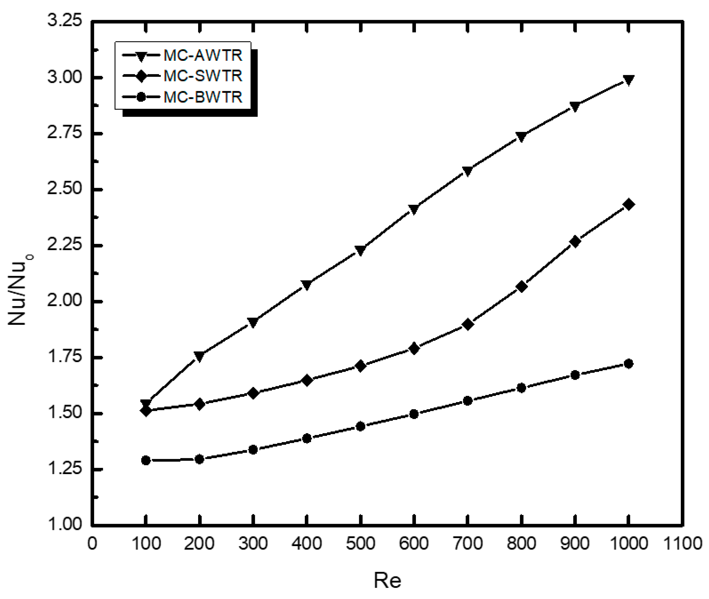
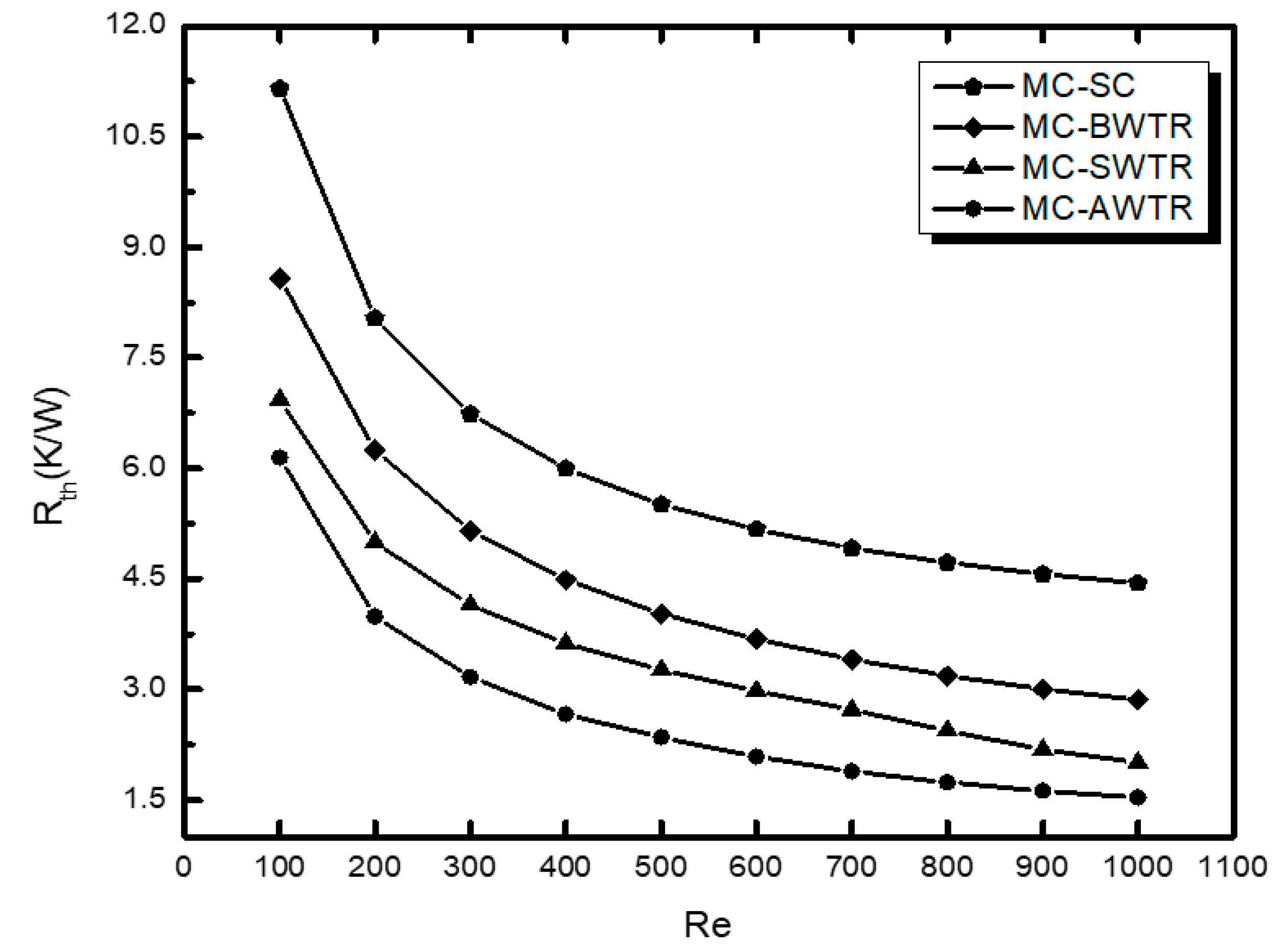
  • The addition of trefoil ribs to any wall improved heat transfer characteristic (h and Nu) of MC-SC; the improvement was greater in MC-AWTR followed by MC-SWTR and minimum for MC-BWTR.
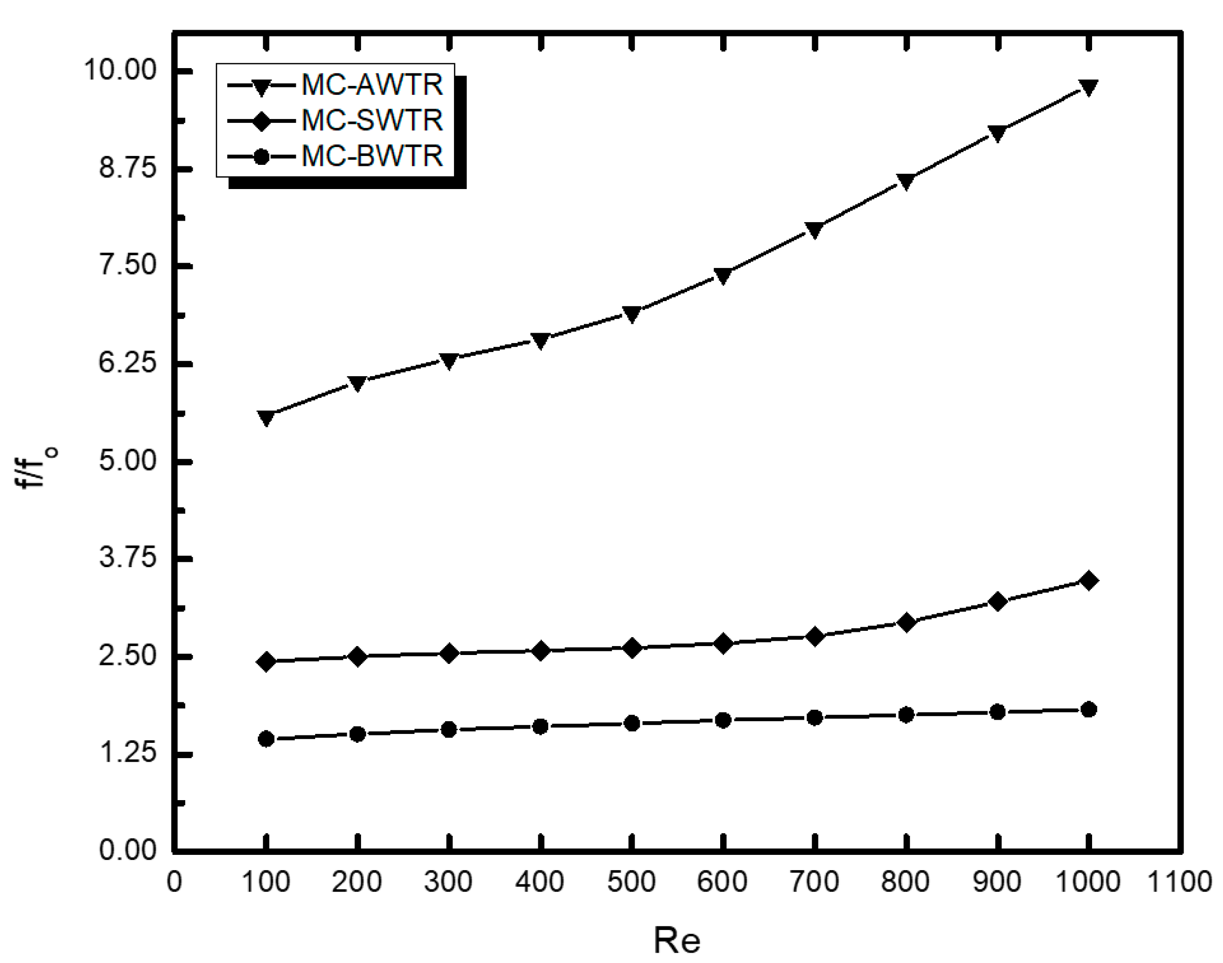
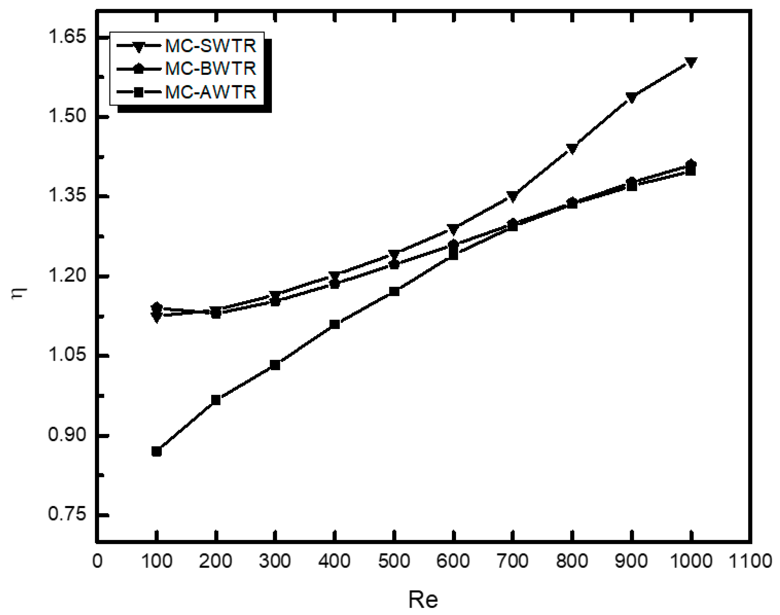
  • The addition of ribs to any wall has increased the friction factor and, hence, the pumping power. This increase is minimum for MC-BWTR and maximum for MC-AWTR, whereas MC-SWTR is moderate. The addition of ribs improves heat transfer at the expense of an increase in the friction factor (pumping power), which is quantified in terms of η. This factor was higher than one in each case, except for MC-AWTR in 100 < Re < 200. The η for the ribbed channel was highest for MC-SWTR followed by MC-BWTR and lowest for MC-AWTR.
  • Although the heat transfer capability of MC-AWTR is superior to others, its overall performance is inferior, thereby confirming that the heat transfer coefficient is not the only criteria for modification of MC-SC. On the other hand, the overall heat transfer enhancement of MC-SWTR was higher than any other case throughout the study, and its value was significantly high in Re > 700.
  • Moreover, η increases with Re for each case, which confirms that the increment in Nu with Re is more significant than the increment in Δ p . The highest η value of 1.6 is attained for MC-SWTR at Re = 1000. By contrast, the lowest value of 0.87 was achieved for MC-AWTR at Re = 100.

Author Contributions

Conceptualization, F.A., S.A. and K.A.; methodology, K.A., S.A, F.A. and N.H.; validation, K.A., S.A, F.A., N.H., M.A., K.G., A.V. and D.Y.P.; investigation, S.A., K.A., F.A. and N.H.; writing—original draft preparation, S.A. and F.A.; writing—review and editing, M.A., K.G, A.V. and D.Y.P. All authors have read and agreed to the published version of the manuscript.

Funding

This research received no external funding.

Institutional Review Board Statement

Not applicable.

Informed Consent Statement

Not applicable.

Data Availability Statement

The data presented in this study are available upon request.

Acknowledgments

The authors acknowledge the support of UET Peshawar and Air University, Islamabad, for providing the computational facilities to conduct this research study.

Conflicts of Interest

The authors declare no conflict of interest.

Nomenclature

MCHSMicrochannel heat sink
MC-AWTRAll wall trefoil ribbed microchannel
MC-AWSRSide wall trefoil ribbed microchannel
MC-AWBRBase wall trefoil ribbed microchannel
ReReynolds number
NuNusselt number
fFriction factor
LLength of the MCHS (mm)
HchHeight of the channel (mm)
WchWidth of the channel (mm)
DhHydraulic diameter (mm)
ΔTTemperature difference (K)
∆pPressure drop (Pa)
qwWall flux (W/cm2)
CpSpecific heat capacity at constant pressure (J/kg K)
µDynamic viscosity (kg/ms)
kThermal conductivity (W/mK)
ρDensity (kg/m3)
ηThermal enhancement factor

References

  1. Xu, M.; Lu, H.; Gong, L.; Chai, J.C.; Duan, X. Parametric numerical study of the flow and heat transfer in microchannel with dimples. Int. Commun. Heat Mass Transf. 2016, 76, 348–357. [Google Scholar] [CrossRef] [Green Version]
  2. Tuckerman, D.B.; Pease, R.F.W. High-performance heat sinking for VLSI. IEEE Electron Device Lett. 1981, 2, 126–129. [Google Scholar] [CrossRef]
  3. Ahmad, F.; Cheema, T.A.; Ur Rehman, M.M.; Abbas, A.; Woo Park, C. Thermal enhancement of microchannel heat sink using rib surface refinements. Numer. Heat Transf. Part A Appl. 2019, 76, 851–870. [Google Scholar] [CrossRef]
  4. Liu, X.; Yu, J. Numerical study on performances of mini-channel heat sinks with non-uniform inlets. Appl. Therm. Eng. 2016, 93, 856–864. [Google Scholar] [CrossRef]
  5. Rehman, M.M.U.; Cheema, T.A.; Ahmad, F.; Khan, M.; Abbas, A. Thermodynamic Assessment of Microchannel Heat Sinks with Novel Sidewall Ribs. J. Thermophys. Heat Transf. 2020, 34, 243–254. [Google Scholar] [CrossRef]
  6. Ali, S.; Ahmad, F.; Hassan, M.; Rehman, Z.; Wadood, A.; Ahmad, K.; Park, H. Thermo-fluid Characteristics of Microchannel Heat Sink with Multi-configuration NACA 2412 Hydrofoil Ribs. IEEE Access 2021, 9, 128407–128416. [Google Scholar] [CrossRef]
  7. Rehman, M.M.U.; Cheema, T.A.; Ahmad, F.; Abbas, A.; Malik, M.S. Numerical investigation of heat transfer enhancement and fluid flow characteristics in a microchannel heat sink with different wall/design configurations of protrusions/dimples. Heat Mass Transf. 2020, 56, 239–255. [Google Scholar] [CrossRef]
  8. Zhu, Q.; Chang, K.; Chen, J.; Zhang, X.; Xia, H.; Zhang, H.; Wang, H.; Li, H.; Jin, Y. Characteristics of heat transfer and fluid flow in microchannel heat sinks with rectangular grooves and different shaped ribs. Alex. Eng. J. 2020, 59, 4593–4609. [Google Scholar] [CrossRef]
  9. Xiao, H.; Liu, Z.; Liu, W. Turbulent heat transfer enhancement in the mini-channel by enhancing the original flow pattern with v-ribs. Int. J. Heat Mass Transf. 2020, 163, 120378. [Google Scholar] [CrossRef]
  10. Hassani, S.M.; Khoshvaght-Aliabadi, M.; Mazloumi, S.H.; Rehman, S.; Alimoradi, A. Improving thermal performance of microchannels by combining rectangular pin with chamber. Appl. Therm. Eng. 2021, 186, 116373. [Google Scholar] [CrossRef]
  11. Ahmad, F.; Cheema, T.A.; Mohib Ur Rehman, M.; Ilyas, M.; Park, C.W. Thermodynamic analysis of microchannel heat sink with cylindrical ribs and cavities. J. Heat Transf. 2020, 142, 092503. [Google Scholar] [CrossRef]
  12. Yang, D.; Jin, Z.; Wang, Y.; Ding, G.; Wang, G. Heat removal capacity of laminar coolant flow in a micro channel heat sink with different pin fins. Int. J. Heat Mass Transf. 2017, 113, 366–372. [Google Scholar] [CrossRef]
  13. Naqiuddin, N.H.; Saw, L.H.; Yew, M.C.; Yusof, F.; Ng, T.C.; Yew, M.K. Overview of micro-channel design for high heat flux application. Renew. Sustain. Energy Rev. 2018, 82, 901–914. [Google Scholar] [CrossRef]
  14. Wang, G.; Chen, T.; Tian, M.; Ding, G. Fluid and heat transfer characteristics of microchannel heat sink with truncated rib on sidewall. Int. J. Heat Mass Transf. 2020, 148, 119142. [Google Scholar] [CrossRef]
  15. Chuan, L.; Wang, X.D.; Wang, T.H.; Yan, W.M. Fluid flow and heat transfer in microchannel heat sink based on porous fin design concept. Int. Commun. Heat Mass Transf. 2015, 65, 52–57. [Google Scholar] [CrossRef]
  16. Wang, T.H.; Wu, H.C.; Meng, J.H.; Yan, W.M. Optimization of a double-layered microchannel heat sink with semi-porous-ribs by multi-objective genetic algorithm. Int. J. Heat Mass Transf. 2020, 149, 119217. [Google Scholar] [CrossRef]
  17. Ahmad, F.; Cheema, T.A.; Khan, A.; Mohib-Ur-Rehman, M.; Yildizhan, H. Hydrothermal Investigation of the Performance of Microchannel Heat Sink with Ribs Employed on Side Walls. J. Non-Equilib. Thermodyn. 2021. [Google Scholar] [CrossRef]
  18. Moradikazerouni, A.; Afrand, M.; Alsarraf, J.; Mahian, O.; Wongwises, S.; Tran, M.D. Comparison of the effect of five different entrance channel shapes of a micro-channel heat sink in forced convection with application to cooling a supercomputer circuit board. Appl. Therm. Eng. 2019, 150, 1078–1089. [Google Scholar] [CrossRef]
  19. Karwa, R.; Sharma, C.; Karwa, N. Performance evaluation criterion at equal pumping power for enhanced performance heat transfer surfaces. J. Sol. Energy 2013, 37, 23–32. [Google Scholar] [CrossRef] [Green Version]
  20. Steinke, M.E.; Kandlikar, S.G. Single-phase liquid friction factors in microchannels. Int. J. Therm. Sci. 2006, 45, 1073–1083. [Google Scholar] [CrossRef]
  21. Wang, G.; Niu, D.; Xie, F.; Wang, Y.; Zhao, X.; Ding, G. Experimental and numerical investigation of a microchannel heat sink (MCHS) with micro-scale ribs and grooves for chip cooling. Appl. Therm. Eng. 2015, 85, 61–70. [Google Scholar] [CrossRef]
Figure 1. Computational domain of (a,b) MC-BWTR, (c,d) MC-SWTR, (e,f) MC-AWTR and (g) geometric details of trefoil rib.
Energies 14 06764 g001
Figure 2. Validation of (a) Nusselt number and (b) friction factor with Wang et al. [21].
Energies 14 06764 g002
Figure 3. Temperature distribution of MCHS with trefoil shaped ribs attached to different walls.
Energies 14 06764 g003
Figure 4. Pressure distribution of MCHS with trefoil shape ribs attached to different walls.
Energies 14 06764 g004
Figure 5. Comparison of pressure drop for various wall configurations MCHS.
Energies 14 06764 g005
Figure 6. Comparison of heat transfer coefficient for different wall configurations of MCHS.
Energies 14 06764 g006
Figure 7. Comparison of friction factor ratio for different wall configurations MCHS.
Energies 14 06764 g007
Figure 8. Comparison of Nusselt number for different wall configurations MCHS.
Energies 14 06764 g008
Figure 9. Comparison of Nusselt number ratio for different wall configurations MCHS.
Energies 14 06764 g009
Figure 10. Comparison of thermal enhancement factor for different wall configurations MCHS.
Energies 14 06764 g010
Figure 11. Comparison of total thermal resistance for different wall configurations MCHS.
Energies 14 06764 g011
Table 1. Thermophysical properties of materials.
ρ (kg/m3)Cp (/kg/K)k (W/m/K)µ (kg/m/s)
Copper8978381387.6
Water998.248120.60.001003
Table 2. Mesh independence test.
Mesh NoNo of ElementsPressure Drop (Pa)Error (%)NuError (%)
1568,9564342.4780.5811.682550.83
2691,1944350.4750.3411.652810.58
3811,6464360.4150.1711.639140.46
4963,9764366.1390.03811.652630.058
51,231,5604367.813 11.58557
Publisher’s Note: MDPI stays neutral with regard to jurisdictional claims in published maps and institutional affiliations.

