Abstract
The development of electric aircraft is becoming an important technology for achieving the goals set by the European Commission for the reduction of gases emissions by 2050 in the aeronautical transportation system. However, there is a technology gap between the current values of specific power in commercial electric machines and those required for aeronautical applications. Therefore, the search for alternative materials and non-conventional designs is mandatory. One emergent solution is using superconducting machines and systems to overcome the current limits of conventional electrical machines. This work reviews the new hybrid and all-electric aircraft tendencies, complementing it with recent research on the design and development of high specific power superconducting machines. This includes the main topologies for hybrid and all-electric aircraft, with an overview of the ongoing worldwide projects of these aircraft types, systematizing the main characteristics of their propulsion systems. It also includes the research on superconducting machines to achieve high specific power and consider the impact on the redesign of aircraft systems, the electrical, cooling, and fuel source systems.
1. Introduction
In 2011, the EU published the Flightpath 2050: Europe’s Vision for Aviation report, with goals for commercial aircraft until 2050 [1]. The goals are to reduce 75% in emissions, 90% in and 65% in noise emission due to flying. In 2019, NASA also set similar goals, but for 2035 [2]. To meet these goals, the Advanced Research Projects Agency-Energy (ARPA-E) started, in the same year, a funded project for the development of an all-electric aircraft, with clear targets for efficiency, specific power, power, speed, and costs [3]. These two long-term projects from NASA and ARPA-E incited worldwide research for the development of Hybrid-Electric Aircraft (HEA) and All-Electric Aircraft (AEA).
The research of aircraft electrification has been a research topic since the 1980s. In 1985, NASA issued a technical report [4] detailing a study in which replacing several conventional systems with electrical ones could reduce the aircraft’s empty weight by 10%, consequently reducing required engine thrust and fuel consumption by 13% and 9%, respectively. This electrification was first effectively started by electrically controlling the surface actuators, such as ailerons, elevators, rudders, and spoilers, which were previously controlled using mechanical and hydro-mechanical systems [5]. Another development towards electrification was the replacement of hydraulic systems by electrical equivalents, such as the landing gear and the wing anti-icing protection. Their replacement with electrical systems raises the electric power requirements, increasing the need for more available power and thus a need for a higher number/volume of energy sources [6]. However, the advantages of using electrical systems are relevant. The reduction in weight and fuel consumption and the reductions in engine noise and emissions are possible with electrical systems, increasing the overall efficiency of the aircraft’s powertrain [4,5]. This initial research served as a consolidation step for more exhaustive research in power electronics, fault-tolerant power distribution systems, and electrically driven actuators for More Electric Aircraft (MEA) [5,7,8,9,10,11]. Successful implementations of the MEA are the Boeing 787 [12], and the Airbus A380 [6], with variable frequency starter-generators mechanically coupled to the aircraft jet engines. The starter-generators, coupled with a battery pack, provide all the electric power required, successfully electrifying most aircraft auxiliary systems.
With the successes of Boeing and Airbus, and combining with the policy targets for 2035 and 2050, the aeronautic industry is shifting to hybrid and electric solutions for commercial aircraft. Although there is extensive knowledge and research in these areas, few projects and companies have invested in electric solutions. Also, there is still a technological gap between the current values of specific power in commercial electric machines and the ones required for aeronautical applications. Therefore, the search for alternative materials and non-conventional designs is mandatory. One emergent solution is using superconducting machines (SMs) to overcome specific power limits of current electrical machines. Although there is research on SMs for aircraft applications and a wide range of research on the HEA and AEA subjects with the possibility of using SM technology [13,14,15,16,17], few analyze this through an integrative view involving the electrical machine, the cooling system, and new types of energy sources. Taking this view into account, the objective of this review article is to analyze research on superconducting electrical machines but now considering their impact on the redesign of aircraft systems: electrical, cooling, and fuel source.
This article is structured in the following way: first, it is made a review of HEAs and AEAs, where the differences from conventional aircraft are shown, and the most common proposed topologies are presented. Afterward, an overview of the ongoing worldwide projects of these aircraft is shown, collecting the common characteristics of the propulsion systems. In the following section, using the information of the previous section, the propulsion system is discussed, focusing on the energy source and the propulsion system. The next section reviews SM for high specific power applications, focusing on projects under development and prototypes, not excluding initial design and simulations. Next, the information on HEA and AEA will be complemented with the SM, and a discussion on the implications of implementing SM in the aircraft’s propulsion system is made. Finally, the conclusions are drawn, retaining the main topics of this review article.
2. Hybrid and All-Electric Aircraft
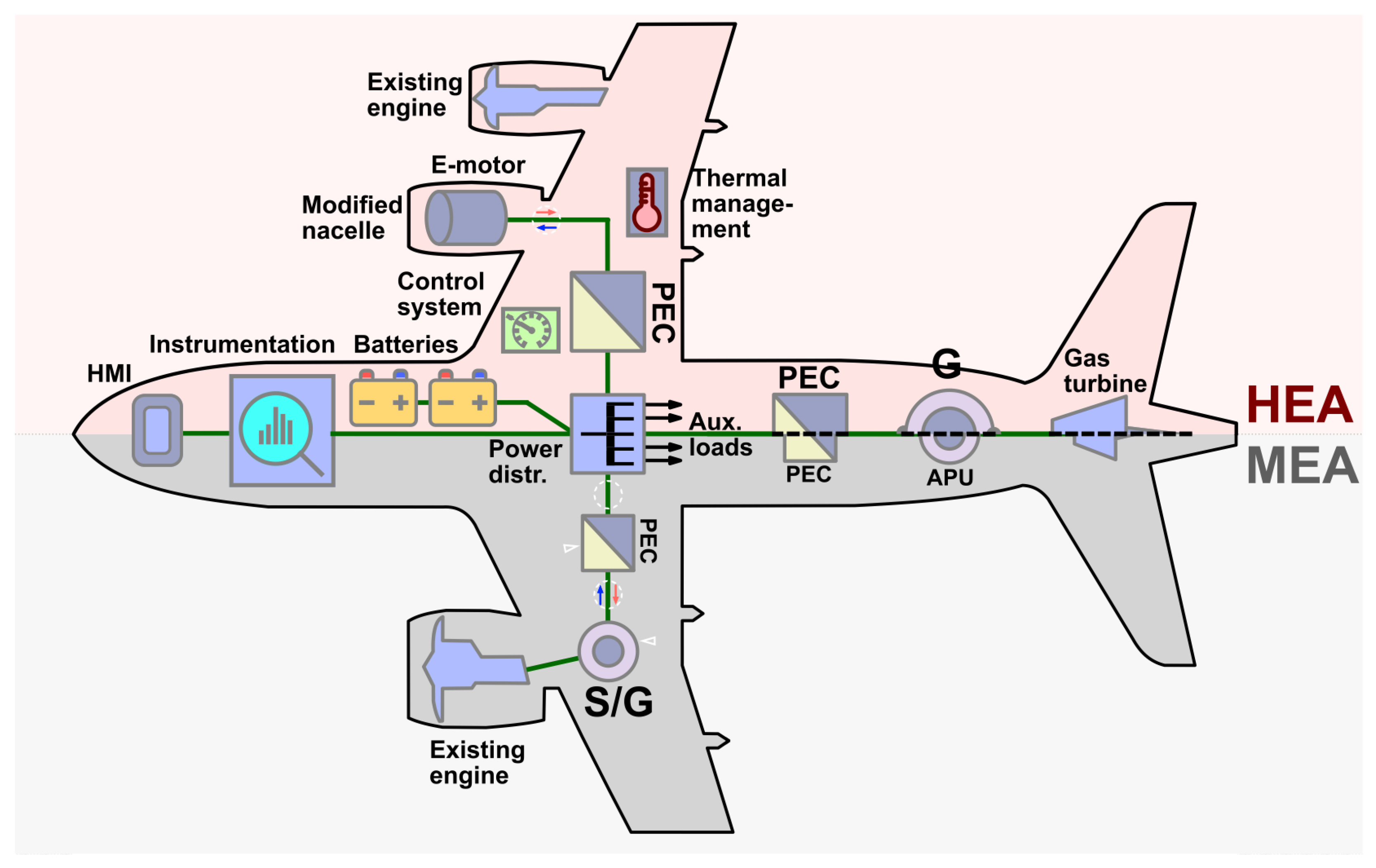
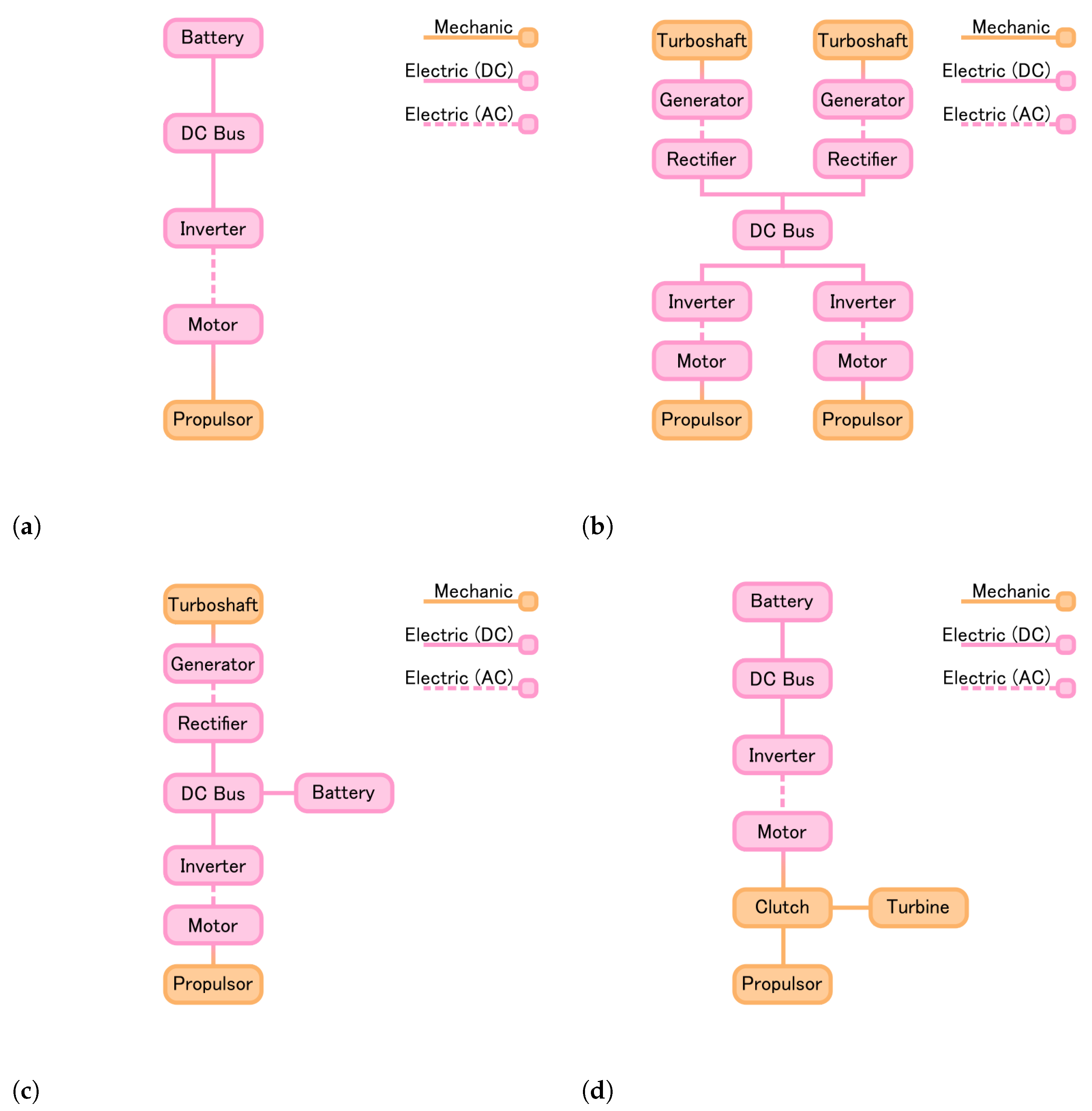
Hybrid-Electric Aircraft are categorized by having electrical and mechanical power sources or powertrains, depending on the configuration. The most common configurations for HEA have a power source of combustion type, with all-electric propulsion, or a combination of combustion and electrical propulsion (see Figure 1). To complement the energy source, batteries are present in most of the hybrid topologies. Ref. [18] refers to different degrees of hybridization, starting from a turboelectric configuration and ending in the all-electric configuration (Figure 2).
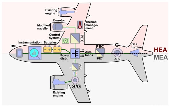
Figure 1.
Side-by-side comparison of the MEA and HEA main topologies. Adapted from [11], licensed under CC BY 4.0.
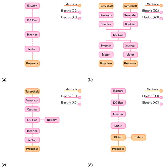
Figure 2.
Main topologies for aircraft hybridization. (Adapted from [18]). (a) All Electric; (b) Twin Turboelectric; (c) Hybrid Series; (d) Hybrid Parallel.
In the turboelectric topologies, the reconfiguration of the architecture of the powertrain system is similar to the MEA concept used in [6,12], as seen in Figure 1. In the MEA, the propulsion system provides the main power source, having an auxiliary power unit with a gas turbine in the aircraft’s tail. Only the gas turbines and generator in the tail are used in a HEA with a turboelectric configuration, removing the need for a starter-generator coupled with the propulsion engines, since smaller motors can directly start them, or not having them all if the propulsion is fully electric.
For the series and parallel hybrid configuration (Figure 2c,d), batteries are used as an additional power source. Hence, depending on the size of the aircraft, the batteries can be the main power source or a secondary auxiliary source. This additional energy source proves to be advantageous. Not only does it increase redundancy in the powertrain system, with two power sources, but it is also possible to perform balance management, optimizing on what level one system is the main source and the other is the auxiliary source [19].
Lastly, in AEA configuration, complete electrification of the aircraft is the end goal of [1,2]. Its propulsive power is provided by electrochemical energy, stored in batteries or fuel cells, to electric motors coupled to propulsors. The main configurations of AEA were discussed in [20], and the most promising topology is of a distributed propulsion kind, using several smaller electric motors (1 to 2 MW) distributed along with the aircraft. As stated in [20], the development and manufacturing of electric motors on the 1 to 2 MW power are currently achievable and economical compared to larger, higher power electric motors. An additional advantage of distributed propulsion is the availability of developing electric machines of this size in the next few years, making prototypes and testing possible for AEAs.
2.1. Worldwide Projects
2.1.1. NASA STARC-ABL
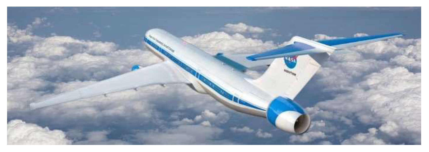
The STARC-ABL (Figure 3) is a 150-passenger class commercial transport concept with a traditional “tube-and-wing” shape [21]. It is a turboelectric HEA concept developed by NASA. It combines several experiences from projects such as Subsonic Ultra Green Aircraft Research (SUGAR) and N3-X [22]. Like a traditional aircraft, the STARC-ABL has two jet engines mounted under each wing, and each engine is coupled to an electric generator. The generated electric power is transmitted to the aircraft’s tail, where an all-electric propulsor is mounted. This propulsion configuration not only reduces the drag but also takes advantage of this extra flow to produce more trust, improving fuel efficiency [23]. The specifications of the STARC-ABL achieve a cruising speed of 0.7 Mach (about 835 km/h), with a mission range of 6500 km. To achieve this, each engine generates electrical power of roughly 1.4 MW, and the all-electric propulsor provides a thrust power of 2.61 MW [24]. This project is currently active, and the necessary technology to develop a prototype is expected to be available from 2030 to 2035 [22].
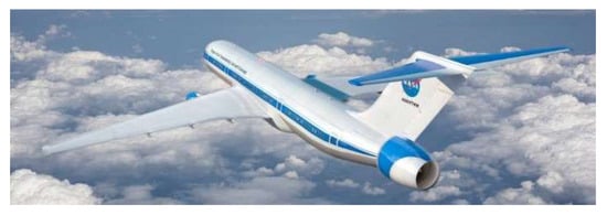
Figure 3.
STARC-ABL concept aircraft.
2.1.2. NASA N3-X
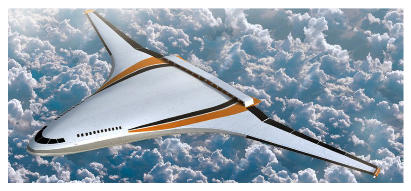
Another NASA project, the N3-X (Figure 4), is a fully turboelectric aircraft with distributed propulsion to reduce over 70% of fuel consumption [25]. The technology proposed for the propulsion is a superconducting one, spanning 16 SC motors through the aircraft’s tail, all supplied by turboshaft engines, each in the tip of the wing. Coupled with the turboshafts are two electrical generators, also superconducting. The use of SC machines is due to their high efficiency and high specific power [26,27,28,29]. This aircraft makes the electric power transmission with SC power cables and cryogenic power inverters and rectifiers. For cooling, it is used liquid Hydrogen () directly or by a reverse Brayton cycle refrigerator cryocooler. The is also used to supply a portion of the fuel for the turboshafts. The aircraft is expected to have a cruising speed of 0.84 Mach (1029 km/h), a mission range of 13,890 km, and a carrying capacity of 300 pax [22]. At cruise speed, the total thrust power provided by the SC motors is 25 MW (1.56 MW each motor) [30]. The design improvements allow the reduction of aerodynamic drag of by 80% and a noise reduction to 64 Effective perceived noise in decibels (EPNdB) [31]. Considering the availability of new electric propulsion technology and new electric power transmission systems, a maiden flight is scheduled for 2040 [32].
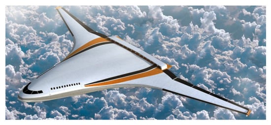
Figure 4.
N3-X concept aircraft.
2.1.3. Airbus E-Fan X
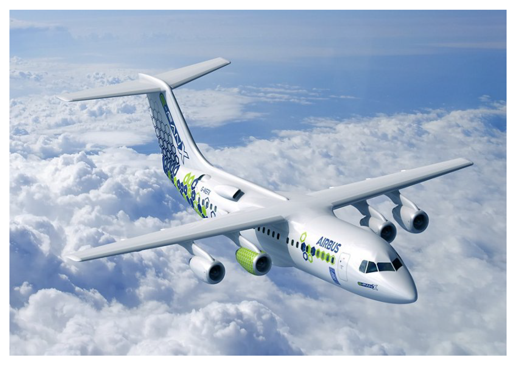
E-FAN X (Figure 5) is a project led by Airbus, Rolls Royce, and Siemens, canceled in 2020. It was expected the first test flight in 2021. The project’s aircraft, the BAe 146, was powered by four engines. One propulsion unit was powered by a 2 MW electric motor connected to a 3 kV onboard power supply via an inverter. It was a serial hybrid system, with a built-in gas turbine driving a 2.5 MW electric generator in the fuselage, with 2 MW of available power from batteries. The platform is designed to explore challenges such as thermal management, altitude, and dynamic effects in high-performance electrical propulsion systems while maintaining high reliability and safety [22]. The E-FAN X, being the first prototype and conception of a partial hybrid aircraft, had some major problems regarding its hybridization. In [33], an exhaustive analysis of this project’s economic and technological viability is made. It is concluded there that, due to the increased weight, the installed batteries had a mass of 2000 kg, making the project not viable. The added power does not support this significant increase in weight since batteries currently have low specific power (1 kW/kg), decreasing the aircraft’s payload weight. This, in turn, increases the costs per passenger in every aspect for the E-FAN X. The author in [33] also states that, even without added batteries, the E-FAN X still needs to reduce payload weight, which makes this project not viable compared to conventional combustion engine aircraft of the same type. However, it ends with a good remark on the project: due to reusing a BAe 146, there was no margin for design and aerodynamic optimization. One way to improve this project is to consider the design and parameter optimization of a new aircraft.
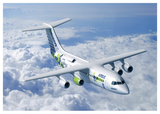
Figure 5.
E-FAN X concept aircraft. The green engine was substituted by an electric motor.
3. Propulsion System Requirements
The propulsion systems for the HEA and AEA can be sectioned into three parts: the energy source, the power transmission, and the propulsion system. Each of these is a critical part of the propulsion system, with the same relevance, and importance. In this section, a detailed discussion of the energy sources and the propulsion is made, not focusing on power transmission. Power transmission is a complex system on its own, having added complexity in aircraft applications, which deserves a separate topic on its own. However, for some information about power transmission systems, see, for example, [9,10,20,22].
3.1. Energy Source
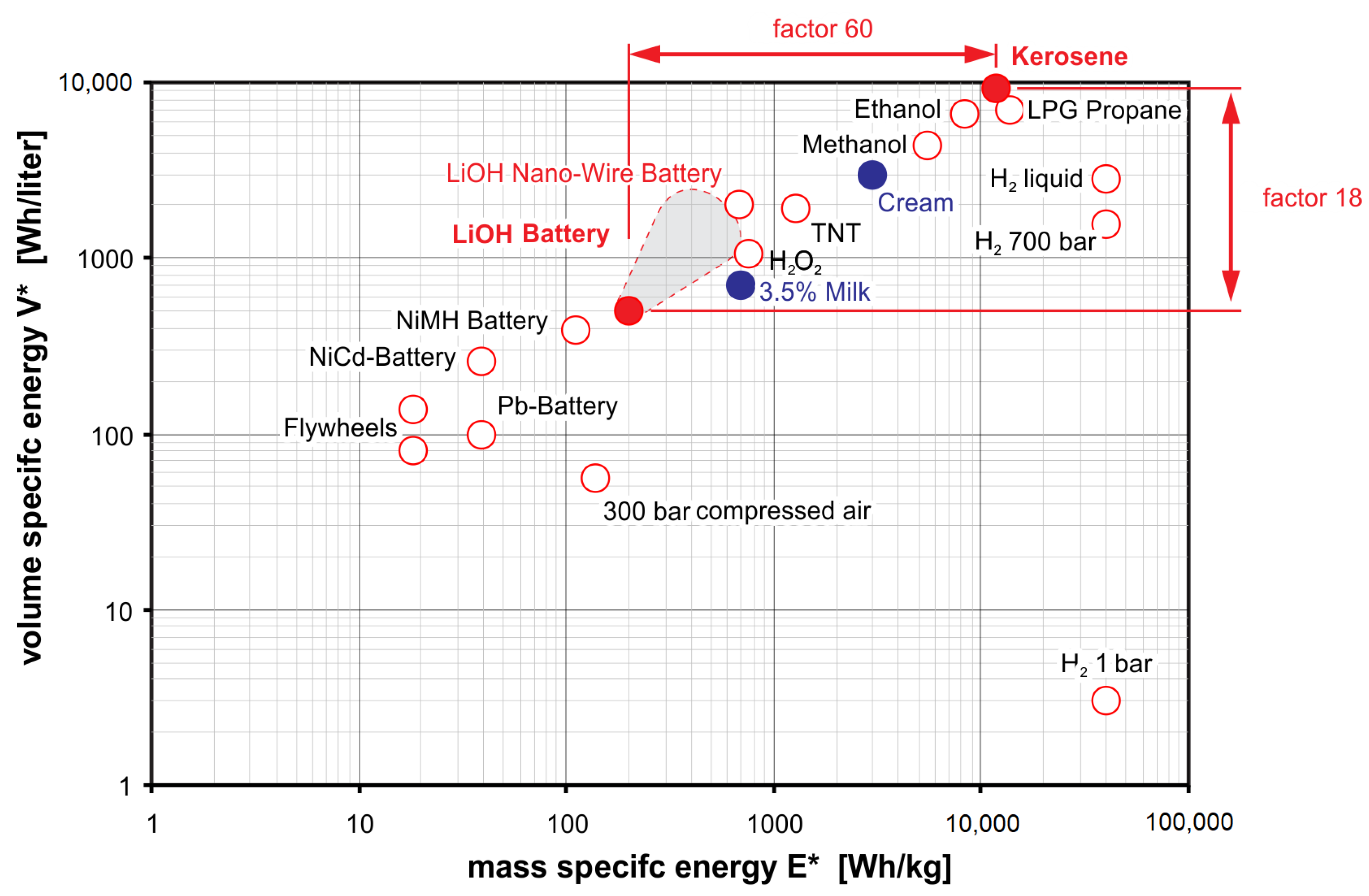
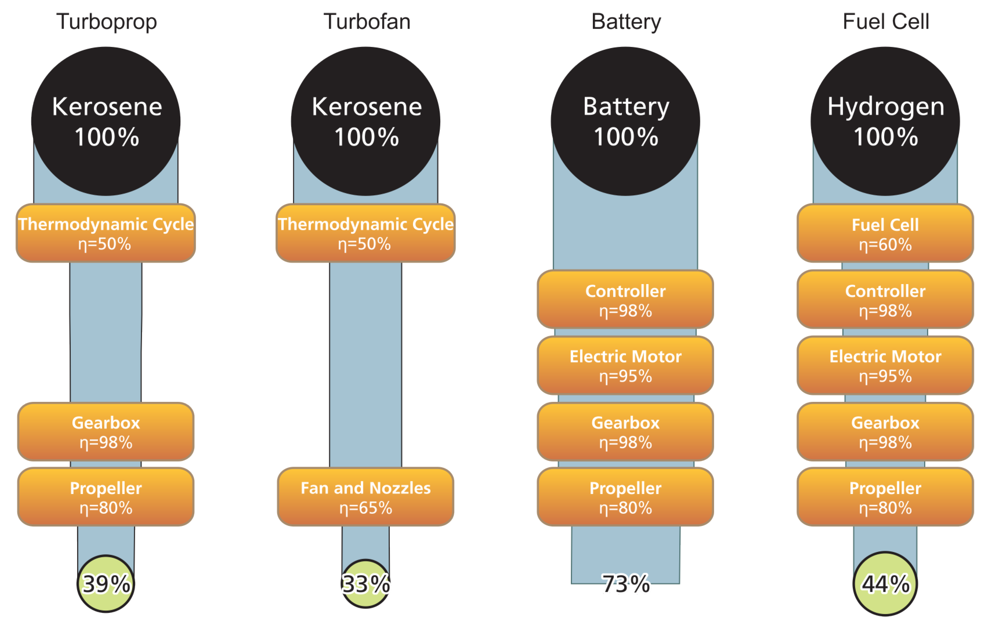
For the HEA and AEA configurations, the selection of energy sources varies. In HEA, fuel combustion is still used, so using conventional jet fuel (kerosene) is still applicable. However, if gas turbines are used for power generation, other fuel sources, such as hydrogen or methane, can be used. For the auxiliary energy source, batteries or fuel cells can be used. On the other hand, in AEA, only electrochemical options are available: batteries and fuel cells. To discuss and compare each energy source, consider a typical 200 passenger commercial aircraft, which uses kerosene as a fuel source. To compare different energy sources, their specific energy, be it volumetric (kW/), or gravimetric (kW/kg) are key. Figure 6 resumes the specific energy of different energy sources. Kerosene has sixty times higher mass-specific energy than batteries and eighteen times higher volume-specific energy. For a full comparison, the efficiency of both energy sources must be considered. Using the values in Figure 7 of [34], the overall efficiency of a system using kerosene is about 39%, while typical Li-ion batteries propulsion systems have an overall efficiency of 73%. Considering these efficiency values, the specific energy gap between both sources is narrower but still significant. Batteries still are around 32 times heavier and 10 times larger. This is a clear disadvantage for aircraft since their mass and volume are important characteristics, affecting their thrust-to-weight ratio, terminal velocity, and maximum take-off weight. Therefore, the current battery technology is not suited for large aircraft applications.
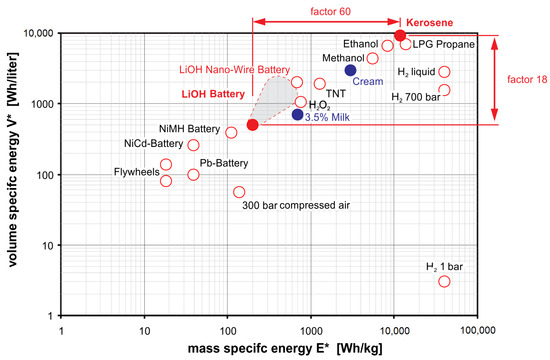
Figure 6.
Volume and mass-specific energy characteristics of different types of energy sources [34]. Credits: NATO.
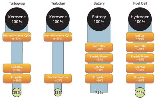
Figure 7.
Typical onboard conversion chains with typical component efficiencies and total chain efficiency [34]. Credits: NATO.
Fuel cells, with their use of hydrogen, can be a good candidate for AEA applications. Using the data from Figure 6, liquid hydrogen has four times higher mass-specific energy while having a third of the volume-specific energy of kerosene. Using the values of [34], both systems have similar overall efficiency, which indicates that less mass is required using hydrogen, while storage volume must increase. Both systems are similar, indicating viability to use fuel cells in AEA. These calculations were done using liquid hydrogen, stored at a temperature below .
3.2. Electric Propulsion
There are two major aspects to consider in the electric propulsion of HEA and AEA: specific power and efficiency. The current commercially available electric motors can achieve specific powers of around 4 to 10 kW/kg, proving sufficient for smaller aircraft, e.g., 2-seaters [35]. However, for passenger-class aircraft, there is a need for specific powers higher than 10 kW/kg [27]. One example is the NASA project, the STARC-ABL, referred to in Section 3, which is projected to have electric motors with a specific power of 13 kW/kg. This indicates that there is a need to develop a new kind of electric motor with higher specific powers. One possible solution for this challenge is the use of superconducting materials. Ref. [29] specify target estimations for SC machines of 20 kW/kg to 30 kW/kg, respectively. These values are surplus for the current needs in electric aircraft projects, increasing the viability of HEA and AEA. Another advantage is the estimated efficiency of SC motors when compared to conventional motors. Although already in the 98% range for typical large power electric motors [35], the SC motors prove to have higher efficiency [36]. Combining their high efficiency and high specific power, there is a promise for efficient, more compact electric motors for aircraft applications. One could argue that if SC motors have a 1% increase in efficiency is not a great achievement when discussing already high efficiencies. However, 1% in the reduction of energy consumption in the scale of an aircraft (power of the order of MW and energy consumptions of the order of MWh) can lead to savings in fuel.
Another advantage of using electrical propulsion with high specific power is allowing distributed propulsion. Using distributed propulsion, new aircraft designs are possible, allowing a more aerodynamic aircraft. This, in turn, can lead to higher efficiency and safety, cost reduction, and decreased noise [20]. A distributed propulsion system can be considered safer due to its increased redundancy. This is what the N3-X design referred to in Section 2.1.2 proposes. Its distributed propulsion is sectioned into 4 sectors, each with 4 electric motors. Each sector must be designed to provide 50% of the total required thrust power, giving extra redundancy in the propulsion, ensuring a proper flight or a safe landing in case of a single or multiple motor failure.
3.3. Cooling
For aircraft propulsion, the cooling system is an important aspect for the efficiency and reliability of engines in a conventional aircraft, or in case of electric propulsion, in an HEA or AEA. Conventional aircraft uses oil or air to cool their engines, which are two effective means for conventional electric machines. However, due to the temperature requirements for superconductivity, SMs need a more complex system for cooling. To achieve a superconducting state, the temperature needs to be lower than 90 K for the new generation of high-temperature superconductors, or lower (around 20 K) for old generations of superconducting materials. Hence, cooling agents such as liquid nitrogen (77 K) and liquid hydrogen (33 K) are possible candidates. This cooling requires additional systems, which will increase the weight and used volume of the aircraft, reducing payload and volume capacity. The best suggested cryogenic systems are ones using reverse-Brayton cycle cryocooler (RBCC), which are already used within aerospace applications, showing high reliability and efficiency, and can take advantage of using superconducting machines as cold heat exchangers [37], not requiring its own cold heat exchanger, sharing the total weight and volume capacity with the electric propulsion. NASA also confirms this in their studies on the N3-X concept, referred to in Section 2.1.2, in which they assume in the design a two-stage RBCC.
Complementing the decision of using as a cooling agent is its use in fuel/energy source. The use of as fuel for the new hybrid/electric aircraft is consensual among several researchers and projects. The Polaris project, a liquid hydrogen turbo-electric transport aircraft [38], is a design concept combining a liquid hydrogen fuel system with superconducting power transmission. First, the reduction of emissions using instead of kerosene are in agreement with the metrics set by EU flightpath 2050 and NASA goals for 2035 [1,2]. Second, using as fuel and cooling can be realized without additional power demand or systems since the needs to be evaporated before being burnt. The Polaris project also discusses how the fuel tanks need to be redesigned to accommodate the temperature and pressure required, and also safety issues regarding the use of . In both cases, the steps and precautions are detailed, ensuring reliable processes for airlines to follow. In [39], a more general study employed by the EU commission is done, analyzing the technological, economic, and climate impact of switching fuel sources to . It states that hydrogen used as a primary energy source for propulsion for fuel cells or direct burn-in thermal (gas turbine) engines can feasibly power aircraft with entry into service by 2035 for short-range aircraft. Costing less than €18 ($20) extra per person on a short-range flight and reducing climate impact by 50 to 90%, hydrogen could play a central role in the future mix of aircraft and propulsion technologies by 2035. Currently, it is not economically viable for medium and long-range flights, although if the hydrogen demand increases overall in several industry sectors, this will mitigate the initial cost disadvantages. Technological-wise, a new redesign of storage and fuel distribution is needed to make it possible for a long-range flight aircraft.
4. Superconducting Electrical Machines
Currently, the literature does not present enough machines for commercial aircraft applications in the prototype stage or more advanced stages. Since superconducting machines are still a trending topic in the research area of electric machines, most machine designs are still in the first stages, in the simulation and modeling phase. The main research is on the properties and limits of superconducting materials. For example, in [40], a review of the challenges in implementing superconducting machines with superconducting ring magnets in the rotor for aircraft applications is presented. Here, the specified challenges are the high-speeds (>16,000 rpm) may influence the performance and limits of the SC ring, the minimum bending radius of SC tapes can be a barrier for machine dimensioning, and transverse tensile stress are a problem when using epoxy resin as the SC ring tape stabilizer. These challenges are mainly mechanical and structure, requiring new engineering solutions for the design and construction of the SCM. AC SC losses are another challenge, as highlighted by [41], especially in cases where the critical current drops due to the interaction with external magnetic fields.
Despite the importance of the challenges above, this section is dedicated to presenting the reader designs of superconducting machines, which are in the prototype state, concerning aircraft applications, with experimental data for nominal power, speed, specific power, and efficiency. These parameters are summarized in Table 1, for each research reviewed. In the following subsections, a detailed explanation of machines with particular interest for commercial aircraft or drawn important conclusions for the design of superconducting machines are made. Particular interest in prototypes and experimental data is sought.

Table 1.
Survey of superconducting machine designs with efficiency and specific power metrics.
4.1. Synchronous Machine with HTS Field Windings
The research in [42] refers to the application of superconductors to the field windings of a synchronous AC generator. It is considered an airborne high-power-density superconducting generator under construction at the authors’ company. The requirements for this application are high specific power, fast startup capability, and high terminal voltage. In this way, a 20 MW synchronous generator was constructed with NbTi superconductor for the field windings, cooled with liquid helium (4.2 K). Operating at around 6000 rpm, it provides power converted to a rectified voltage of 40 kV DC, with a maximum continuous operational run of 5 min. Due to these short runtimes, thermal restrictions and material fatigue are less demanding, making possible the construction of a smaller machine, which allowed a final design with a specific power of 22 kW/kg. In addition, due to the high voltages produced, the lifetime is short. It was selected to be 100 h, which specified an armature insulation system and resulted in a design life of 1200 missions. Because of the nature of this machine, it is not suitable for commercial aircraft applications. Nonetheless, the construction and testing of this application highlight important aspects to be considered in the design of HTS field windings synchronous machines, such as the mechanical stresses in generator’s structure due to high current and magnetic flux densities; the required heat-transfer capacity of the coolants and their total mass flow to maintain the superconducting state in the field coils, and also to effectively cool the generator; the type of shield used, be it ferromagnetic or conductive, shielding the aircraft from the intense magnetic field of the generator.
Another electric motor designed for aerospace propulsion is the one presented in [47]. The motor has been designed for an aerospace distributed fan propulsion system with an aerospace benchmark specification of 1 MW. With superconducting bulk magnets mounted on a conventional rotor core and MgB2 superconducting wires in the stator, the motor is to achieve a speed of 12,000 rpm, operating at a temperature of 20 K, with a final volume of 0.0637 . From the several designs analyzed in the research, two are highlighted here: the 8 pole air core, or coreless, which is a stator air core design, and the 8 poles magnetic stator, which is the conventional ferromagnetic stator. Only simulation results are available, showing that the overall efficiencies are the same between these two designs, 99.37%. The total stator weight is 0.5 kg for the coreless design and 308 kg for the magnetic stator. These differences greatly affect the final specific power, in which the air-core design takes the lead. Considering design strategies, AC losses in the stator are particularly sensitive to the main rotor field. Therefore, in all designs, a magnetic screening is used. Additionally, the temperature restriction of 20 K imposes a significant load on the cryocoolers, especially for the air core design, due to the large air volume of the machine. The best-case scenario for the cryocoolers is the magnetic stator design, which sets the overall efficiency (motor + cryocooler) of 97%. Ref. [47] presents a centralized system with large cryocoolers and liquid methane as a possible solution. This suggests that the new electric aircraft needs a total redesign to accommodate these new systems while guaranteeing their goals.
4.2. Air-Core Radial Flux
In [50], a design of a radial flux, the air-core superconducting synchronous machine is proposed. By removing the iron core and its saturation limits, designs with increased air-gap flux densities can now be considered, due to SC coils’ higher magnetomotive force (MMF) capabilities compared with copper coils. Using similar technology to the magnetic resonance imaging machines, compensating SC coils are used to contain the machine’s magnetic field instead of the conventional iron core.
A basic sizing project was done, showing the design for a , machine. This is indicative of an increase of specific power relative to conventional electric machines, in which [26] points at . One drawback to consider is the length of SC wire needed to achieve the required MMF and effective shielding. The results show a minimum of around 15 km length of SC wire for a magnetic flux density in the armature of 1.5 T. This greatly increases the costs of the motor, using the current price of SC, making it economically inviable. It is stated that by using LTS, the costs are reduced by ten-fold, compared with HTS. Although this is true, the use of LTS requires the system to be cooled in the region of or lower ( for the SC used in [50]). This requires a cooling system that uses liquid helium, and for commercial aircraft applications, it would increase overall production and maintenance costs, which is counterproductive. One air-core design using HTS cooled with liquid hydrogen proves to be more useful due to the cooling and fuel source duality [53].
4.3. Axial-Flux Partially Superconducting Machine
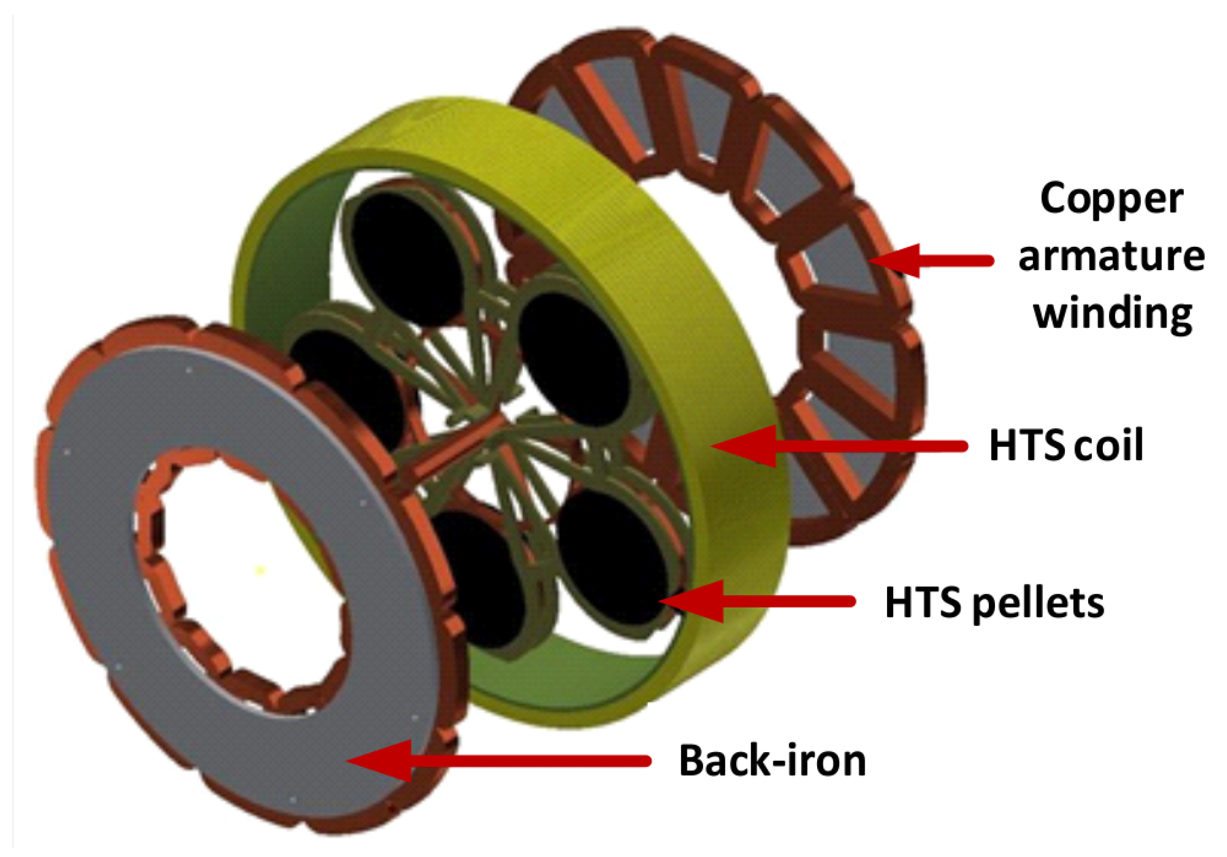
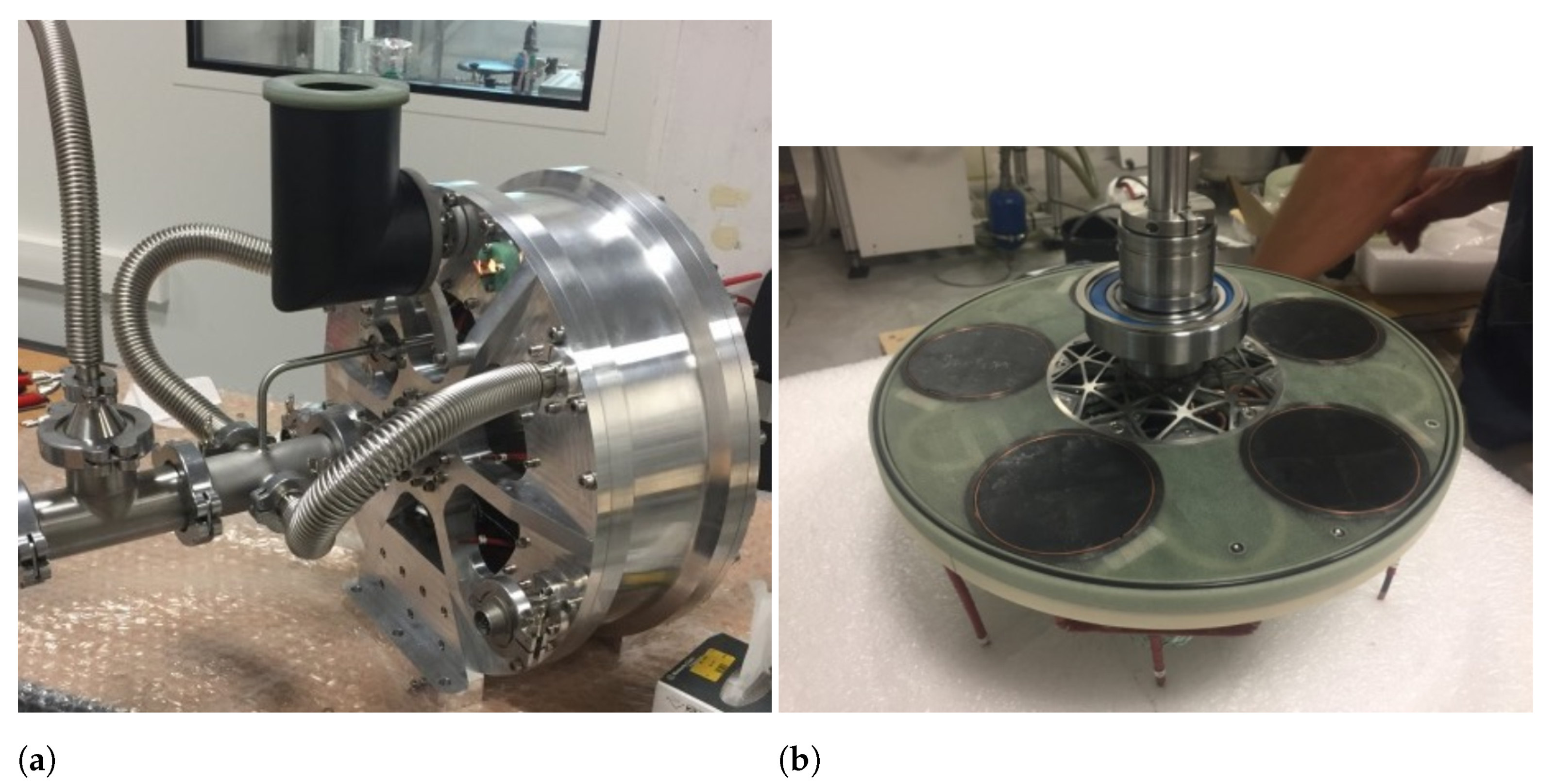
Another design to increase the specific power of electrical machines is the one developed in [46,54,55]. A partially superconducting electrical machine is designed and developed. It is a brushless axial flux machine (Figure 8) designed to avoid all the maintenance and safety issues of a brush system and the additional weight of a rotating diode system. This motor works on the principle of flux modulation. As shown in Figure 8, the HTS coil carries a direct current, which creates the main axial flux of the machine. Due to the diamagnetic nature of the HTS, the pellets create an effective magnetic shield, deviating the flux lines around them, modulating the magnetic flux, creating a space-periodic magnetic flux along the machine’s azimuth. With this modulation, when the HTS shield rotates, it induces a back-electromotive force to the armature winding terminals, effectively creating a synchronous machine.
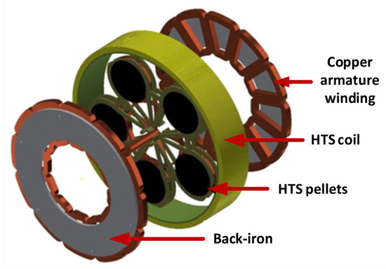
Figure 8.
Concept of axial-flux partially HTS machine from [46], licensed under CC BY 3.0.
To have a high specific power, the machine’s weight is important. In this sense, the materials used in its construction have a higher importance in the design than in conventional machines. The prototype (Figure 9) consists of a rotor (Figure 9b) made with a fiberglass/epoxy composite and titanium support. The HTS pellets are inserted in copper rings, soldered to the copper pipes that provide the cooling. The stator uses concentric double-layer windings with a lower length than distributed windings, successfully reducing its weight. To reduce weight and increase the specific power due to increased magnetic flux density, a thin hollow cylinder of laminated iron is used to support the armature windings. A closed-loop of helium under pressure is used for the cooling of the HTS coil and pellets. The cryostat is made of aluminum to make it more lightweight.
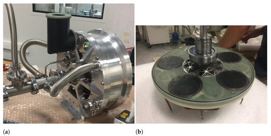
Figure 9.
50 kW superconducting machine prototype from [46], licensed under CC BY 3.0. (a) Prototype withouth cryostat; (b) Rotor.
In [46], a prototype was developed and no-load tests were made. The tests were performed using the prototype as a generator, with a speed of 250 rpm, and with the HTS coil supplied by a current of 120 A. The armature voltage of one winding was measured. The no-load tests showed that the numerical analysis modeled well enough the behavior of the HTS pellets, successfully validating the flux modulation of the machine. Regarding developed voltage, the authors in [46] were expecting phase-to-phase voltage values of 535 V in the armature winding. Using the no-load experimental data, they made linear extrapolations to compute the total phase-to-phase armature voltage as the thin back-iron is rapidly saturated. The total expected armature voltage is between 296 V and 316 V, which do not correspond to the initial predicted value of 535 V. The authors point out two factors. First, the prototype’s final air gap length and the number of turns in the armature windings were modified due to the initial design’s construction feasibility. Second, due to the grain boundaries of the HTS pellets, which are zones where the flux penetration is higher, the modulation of the flux was not following the simulated models, reducing the flux through the armature windings. The final prototype was designed to achieve a power of , with a total weight (machine and cryostat) of . This project is still under development, and the research on superconducting bulk characteristics and machine design is being conducted [54,55].
This design and its prototype is a major breakthrough in the development of new electrical machines for aircraft applications, where the key design aspects are compactness and lightness, while maintaining the same overall power output required for conventional aircraft. However, its maturity is still not reached. First, the specific power is not high enough for aircraft. The machine’s specific power is under , far from the required 15–20 kW/kg stated in Section 3.2. There are some possibilities to increase its specific power. One can consider, inspired by [50], the use of an HTS shielding instead of back iron to reduce machine’s weight, as HTS bulks are less dense than iron ( instead of ), making the machine an air-core one. This can increase the magnetic flux density in the armature, also increasing the induced back-electromotive force.
The windings in the armature can also be made using HTS coils, making a fully superconducting electric machine. Due to their high current and low losses, fewer turns are needed, reducing the armature weight. Losses due to varying magnetic fields and AC currents in HTS coils can be disruptive in their operating conditions, leading to quenching and loss of superconductivity. However, if liquid hydrogen is used for its cooling, the limits of magnetic fields and current densities are higher [56]. Additionally, there are more complex configurations of HTS tapes, such as stacks, Roebel [57], and CORC [58], which can prove useful in increasing the current transport and magnetic flux density creation [59,60].
Regarding the cooling aspects, the use of liquid helium can prove to be a disadvantage over liquid hydrogen or liquid methane since it cannot be used as a fuel source for HEA. Although not directly affecting the machine’s weight, having another reservoir for the cooling agent increases the aircraft’s overall weight, which hinders its performance.
5. Discussion
Several ideas were discussed throughout this article, exposing some major points for the upcoming HEA and AEA. Firstly, it is important to discuss the major aspects of HEA and AEA, which are its powertrain.
The specific power for the electric propulsion of a passenger-class aircraft needs to be higher than 10 kW/kg. The use of superconducting electric motors is expected to allow specific power values to a level around 25 kW/kg. Values of this magnitude significantly reduce the total weight of the aircraft. For example, the Boeing 777 Jet engine has a specific power of 10 kW/kg. Using propulsion with 25 kW/kg, there is a 60% reduction in the mass of the turbine, which can be used to increase the payload. Moreover, superconducting materials make possible the design of electrical machines with an air-core structure and shielding materials, with smaller volumes compared to a typical aircraft jet engine, increasing the aircraft’s volume capacity.
One inconvenience in using superconducting technology is its cooling. To achieve a superconducting state, the temperature needs to be lower than 90 K for the new generation of high-temperature superconductors, or lower (around 20 K) for old generations of superconducting materials. Hence, the use of cooling agents such as liquid nitrogen (77 K) and liquid hydrogen (33 K) are possible candidates. This cooling requires additional systems, which will increase the weight and used volume of the aircraft, reducing payload and volume capacity. The best suggested cryogenic systems are ones using reverse-Brayton cycle cryocooler (RBCC). Additionally, the superconducting machine can be part of the cryocooler in this cooling system, being its cold heat exchange part. In this way, with a carefully combined design of the cooling and propulsion systems, one can seek synergy between them.
For the energy source, a complete electrical source is not possible. As seen in Section 3.1, battery technologies are still far from their applicability in a HEA or AEA, as it requires around 32 times more weight to have the same energy source of kerosene, also being 10 times larger in volume. One possible alternative is to use fuel cells that can use to produce the electric power. has four times more mass-specific energy than kerosene, which increases aircraft payload. However, it needs 3 times the volume capacity of kerosene, which is a clear trade-off between mass and volume.
In HEA, specifically in a turboelectric aircraft, the use of for fuel, together with superconducting propulsion, can prove advantageous. Since superconducting propulsion requires a cryogenic cooling system, and the SCM can be used as the cold heat exchanger part, this same cryogenic cooling system can be used to pump the , which absorbs the heat from the SCM, evaporating it, so it can be used as fuel for the gas turbine. This synergy between these three systems allows weight and volume reduction when comparing it with three independent systems.
Although some possible solutions were provided above, the research reviewed indicates that conventional aircraft designs may not suitable to do substitutions and/or modifications in the powertrain, maintaining the aircraft’s original fuselage. With the projects discussed in Section 2.1, a redesign of the aircraft is sought, not only to accommodate the changes in the powertrain, through a distributed propulsion, and extra redundancies due to the nature of the electrification of the aircraft, but also to take advantage of new designs, aerodynamic-wise. In this sense, with the efforts being made to bring HEA and AEA for the near future, current airliners need to seek designs that can accommodate the cryo-electrification of airplanes.
6. Conclusions
This review article sought to analyze the research on superconducting electrical machines considering their impact on redesigning the electrical, cooling, and fuel systems of aircrafts. It was presented propulsion topologies for aircraft with their main characteristics. An overview of most worldwide projects was shown, stating their propulsion topology and main characteristics. The energy sources and electric propulsion were also discussed, referencing liquid hydrogen as a cooling agent for the aircraft and the superconducting electrical propulsion systems. Finally, two main configurations for superconducting motors were analyzed and discussed.
The need for new designs of aircraft to take advantage of the electrical propulsion systems is of extreme importance to guarantee the projected plans of the EU and NASA. As seen in the NASA projects and the now-canceled E-FAN X project, replacing the propulsion on the aircraft or complete redesign of a distributed propulsion system is key to progress towards lower fuel consumption and lower gas emissions, and an overall increase in efficiency.
Regarding energy sources, batteries have not currently high enough specific powers to be considered for aircraft. Better alternatives lead towards the same end goals, such as using gas turbines, in the turboelectric case or fuel cells, in the all-electric case. Both these systems can use liquid hydrogen (in the fuel cell case, it is mandatory), meaning that the liquid hydrogen can be used as a fuel source or as a cooling agent. This proves advantageous in superconducting electric propulsion, which only requires one reservoir for the fuel and the cooling agent.
Using superconducting electric machines in aircraft can prove quite advantageous regarding efficiency, specific power, and the possibility of a distributed propulsion system. However, special attention must be given to the use of superconductors. Primarily, superconductors are required to be cooled to cryogenic temperatures. This leads to the use of cryogenic systems, which can increase the system’s weight, proving counterproductive to superconducting machines. It is recommended to include the cryocooler system in the design of the machine and the fuel system to allow the possibility of its weight reduction. It is also recommended designs that use a low volume of iron or ferromagnetic materials prioritize ensuring that electric machines are lighter and more compact.
Author Contributions
Conceptualization, P.J.d.C.B. and J.F.P.F.; investigation, F.F.d.S.; writing—original draft preparation, F.F.d.S.; writing—review and editing, F.F.d.S.; supervision, J.F.P.F.; project administration, P.J.d.C.B. All authors have read and agreed to the published version of the manuscript.
Funding
This work was supported by FCT, through IDMEC, under LAETA, project UID/EMS/50022/ 2020, and by FCT fellowship SFRH/BD/145998/2019 to F.F.d.S. as a Ph.D. student at Técnico Lisboa.
Conflicts of Interest
The authors declare no conflict of interest. The funders had no role in the design of the study; in the collection, analyses, or interpretation of data; in the writing of the manuscript, or in the decision to publish the results.
References
- European Commission. Flightpath 2050: Europe’s Vision for Aviation—Report of the High-Level Group on Aviation Research; EU Publications: Luxembourg, 2012. [Google Scholar]
- NASA Aeronautics. NASA Aeronautics Strategic Implementation Plan: 2019 Update; Technical Report NP-2017-01-2352-HQ; National Aeronautics and Space Administration (NASA): Whasington, DC, USA, 2019.
- Advanced Research Projects Agency-Energy (ARPA-E). Aviation-Class Synergistically Cooled Electric-Motors with Integrated Drives (ASCEND) SBIR/STTR. Funding Opportunity No. DE-FOA-0002239. Available online: https://arpa-e-foa.energy.gov/FileContent.aspx?FileID=ba7241ab-ff7d-4e23-b3b4-d947b14b7d89 (accessed on 11 February 2021).
- NASA. Advanced Secondary Power System for Transport Aircraft; Technical Report NASA-TP-2463; National Aeronautics and Space Administration (NASA): Whasington, DC, USA, 1985.
- Naayagi, R.T. A review of more electric aircraft technology. In Proceedings of the 2013 International Conference on Energy Efficient Technologies for Sustainability, Nagercoil, India, 10–12 April 2013; pp. 750–753. [Google Scholar] [CrossRef]
- Adams, C. A380: ‘More Electric’ Aircraft. Available online: https://www.aviationtoday.com/2001/10/01/a380-more-electric-aircraft/ (accessed on 14 July 2021).
- Wheeler, P.; Bozhko, S. The More Electric Aircraft: Technology and challenges. IEEE Electrif. Mag. 2014, 2, 6–12. [Google Scholar] [CrossRef]
- Sarlioglu, B.; Morris, C.T. More Electric Aircraft: Review, Challenges, and Opportunities for Commercial Transport Aircraft. IEEE Trans. Transp. Electrif. 2015, 1, 54–64. [Google Scholar] [CrossRef]
- Chen, J.; Wang, C.; Chen, J. Investigation on the Selection of Electric Power System Architecture for Future More Electric Aircraft. IEEE Trans. Transp. Electrif. 2018, 4, 563–576. [Google Scholar] [CrossRef]
- Buticchi, G.; Bozhko, S.; Liserre, M.; Wheeler, P.; Al-Haddad, K. On-Board Microgrids for the More Electric Aircraft—Technology Review. IEEE Trans. Ind. Electron. 2019, 66, 5588–5599. [Google Scholar] [CrossRef] [Green Version]
- Nøland, J.K.; Leandro, M.; Suul, J.A.; Molinas, M. High-Power Machines and Starter-Generator Topologies for More Electric Aircraft: A Technology Outlook. IEEE Access 2020, 8, 130104–130123. [Google Scholar] [CrossRef]
- Boeing. 787 Propulsion System. Available online: https://www.boeing.com/commercial/aeromagazine/articles/2012_q3/2/ (accessed on 11 June 2021).
- Alexander, R.; Meyer, D.; Wang, J. A Comparison of Electric Vehicle Power Systems to Predict Architectures, Voltage Levels, Power Requirements, and Load Characteristics of the Future All-Electric Aircraft. In Proceedings of the 2018 IEEE Transportation Electrification Conference and Expo (ITEC), Long Beach, CA, USA, 3–15 June 2018; pp. 194–200. [Google Scholar] [CrossRef]
- Cano, T.C.; Rodrmguez, A.; Lamar, D.G.; Castro, I.; Albiol-Tendillo, L.; Khalil, Y.F.; Kshirsagar, P. Future of Electrical Aircraft Energy Power Systems: An architecture review. IEEE Trans. Transp. Electrif. 2021, 7, 1915–1929. [Google Scholar] [CrossRef]
- Schäfer, A.W.; Barrett, S.R.H.; Doyme, K.; Dray, L.M.; Gnadt, A.R.; Self, R.; O’Sullivan, A.; Synodinos, A.P.; Torija, A.J. Technological, economic and environmental prospects of all-electric aircraft. Nat. Energy 2019, 4, 160–166. [Google Scholar] [CrossRef] [Green Version]
- Gnadt, A.R.; Speth, R.L.; Sabnis, J.S.; Barrett, S.R.H. Technical and environmental assessment of all-electric 180-passenger commercial aircraft. Prog. Aerosp. Sci. 2019, 105, 1–30. [Google Scholar] [CrossRef] [Green Version]
- Sahoo, S.; Zhao, X.; Kyprianidis, K. A Review of Concepts, Benefits, and Challenges for Future Electrical Propulsion-Based Aircraft. Aerospace 2020, 7, 44. [Google Scholar] [CrossRef] [Green Version]
- Brelje, B.J.; Martins, J.R.R.A. Electric, hybrid, and turboelectric fixed-wing aircraft: A review of concepts, models, and design approaches. Prog. Aerosp. Sci. 2019, 104, 1–19. [Google Scholar] [CrossRef]
- Hoelzen, J.; Liu, Y.; Bensmann, B.; Winnefeld, C.; Elham, A.; Friedrichs, J.; Hanke-Rauschenbach, R. Conceptual Design of Operation Strategies for Hybrid Electric Aircraft. Energies 2018, 11, 217. [Google Scholar] [CrossRef] [Green Version]
- Barzkar, A.; Ghassemi, M. Electric Power Systems in More and All Electric Aircraft: A Review. IEEE Access 2020, 8, 169314–169332. [Google Scholar] [CrossRef]
- ASAB Projects. Single-Aisle Turboelectric Aircraft with Aft Boundary-Layer Propulsion. Available online: https://sacd.larc.nasa.gov/asab/asab-projects-2/starc-abl/ (accessed on 20 August 2021).
- Schefer, H.; Fauth, L.; Kopp, T.H.; Mallwitz, R.; Friebe, J.; Kurrat, M. Discussion on Electric Power Supply Systems for All Electric Aircraft. IEEE Access 2020, 8, 84188–84216. [Google Scholar] [CrossRef]
- Kratz, J.L.; Thomas, G.L. Dynamic Analysis of the STARC-ABL Propulsion System. In Proceedings of the AIAA Propulsion and Energy 2019 Forum, Indianapolis, IN, USA, 19–22 August 2019. [Google Scholar] [CrossRef] [Green Version]
- Welstead, J.; Felder, J.L. Conceptual Design of a Single-Aisle Turboelectric Commercial Transport with Fuselage Boundary Layer Ingestion. In Proceedings of the 54th AIAA Aerospace Sciences Meeting, San Diego, CA, USA, 4–8 January 2016. [Google Scholar] [CrossRef] [Green Version]
- Dae Kim, H.; Felder, J.L.; Tong, M.T.; Berton, J.J.; Haller, W.J. Turboelectric distributed propulsion benefits on the N3-X Vehicle. Aircr. Eng. Aerosp. Technol. 2014, 86, 558–561. [Google Scholar] [CrossRef]
- Haran, K.S.; Kalsi, S.; Arndt, T.; Karmaker, H.; Badcock, R.; Buckley, B.; Haugan, T.; Izumi, M.; Loder, D.; Bray, J.W.; et al. High power density superconducting rotating machines—Development status and technology roadmap. Supercond. Sci. Technol. 2017, 30, 123002. [Google Scholar] [CrossRef]
- Zhang, X.; Bowman, C.L.; O’Connell, T.C.; Haran, K.S. Large electric machines for aircraft electric propulsion. IET Electr. Power Appl. 2018, 12, 767–779. [Google Scholar] [CrossRef]
- Dezhin, D.; Ivanov, N.; Kovalev, K.; Kobzeva, I.; Semenihin, V. System Approach of Usability of HTS Electrical Machines in Future Electric Aircraft. IEEE Trans. Appl. Supercond. 2018, 28, 1–5. [Google Scholar] [CrossRef]
- Berg, F.; Palmer, J.; Miller, P.; Husband, M.; Dodds, G. HTS Electrical System for a Distributed Propulsion Aircraft. IEEE Trans. Appl. Supercond. 2015, 25, 1–5. [Google Scholar] [CrossRef]
- Armstrong, M.J.; Blackwelder, M.; Bollman, A.; Ross, C.; Campbell, A.; Jones, C.; Norman, P. Architecture, Voltage, and Components for a Turboelectric Distributed Propulsion Electric Grid; Technical Report EDNS04000038188/002; National Aeronautics and Space Administration (NASA): Whasington, DC, USA, 2019. [Google Scholar]
- Madonna, V.; Giangrande, P.; Galea, M. Electrical Power Generation in Aircraft: Review, Challenges, and Opportunities. IEEE Trans. Transp. Electrif. 2018, 4, 646–659. [Google Scholar] [CrossRef]
- Papathakis, K.V.; Kloesel, K.J.; Lin, Y.; Clarke, S.; Ediger, J.J.; Ginn, S. Design and Development of a 200-kW Turbo-Electric Distributed Propulsion Testbed. Available online: https://ntrs.nasa.gov/search.jsp?R=20160009765 (accessed on 20 August 2021).
- Benegas Jayme, D. Evaluation of the Hybrid-Electric Aircraft Project Airbus E-Fan X. Master’s Thesis, Hamburg University of Applied Sciences, Hamburg, Germany, 2019. [Google Scholar]
- Hepperle, M. Electric Flight—Potential and Limitations. Energy Efficient Technologies and Concepts of Operation. 2012. Available online: https://elib.dlr.de/78726/ (accessed on 14 October 2021).
- El-Refaie, A.; Osama, M. High specific power electrical machines: A system perspective. CES Trans. Electr. Mach. Syst. 2019, 3, 88–93. [Google Scholar] [CrossRef]
- Tangudu, J.; Tao, Z.; Kshirsagar, P. Analytical Model and Design Space Studies a Superconducting Machine for an Aircraft Application. In Proceedings of the AIAA Propulsion and Energy 2020 Forum, New Orleans, LA, USA, 24–28 August 2020. [Google Scholar] [CrossRef]
- Palmer, J.; Shehab, E. Modelling of cryogenic cooling system design concepts for superconducting aircraft propulsion. IET Electr. Syst. Transp. 2016, 6, 170–178. [Google Scholar] [CrossRef] [Green Version]
- Dietl, T.; Karger, J.; Kaupe, K.; Pfemeter, A.; Weber, P.; Zakrzewski, A.; Strohmayer, A. Polaris—Design of Liquid Hydrogen Turbo-Electric Transport Aircraft. 2018. Available online: https://www.dglr.de/publikationen/2018/480344.pdf (accessed on 14 October 2021).
- Fuel Cells and Hydrogen Joint Undertaking. Hydrogen-Powered Aviation: A Fact-Based Study of Hydrogen Technology, Economics, and Climate Impact by 2050; FCH JU Publications: Luxembourg, 2020. [Google Scholar]
- Yazdani-Asrami, M.; Zhang, M.; Yuan, W. Challenges for developing high temperature superconducting ring magnets for rotating electric machine applications in future electric aircrafts. J. Magn. Magn. Mater. 2021, 522, 167543. [Google Scholar] [CrossRef]
- Weng, F.; Zhang, M.; Lan, T.; Wang, Y.; Yuan, W. Fully superconducting machine for electric aircraft propulsion: Study of AC loss for HTS stator. Supercond. Sci. Technol. 2020, 33, 104002. [Google Scholar] [CrossRef]
- Gamble, B.B.; Keim, T.A. High-Power-Density Superconducting Generator. J. Energy 1982, 6, 38–44. [Google Scholar] [CrossRef]
- Schiferl, R.F.; Zhang, B.X.; Driscoll, D.I.; Shoykhet, B.A.; Dykhuizen, R.C. Development Status of a 125 Horsepower Superconducting Motor. In Advances in Cryogenic Engineering Materials; Summers, L.T., Ed.; Springer: Boston, MA, USA, 1997; pp. 977–984. [Google Scholar] [CrossRef]
- Nick, W.; Frank, M.; Klaus, G.; Frauenhofer, J.; Neumuller, H.W. Operational Experience With the World’s First 3600 rpm 4 MVA Generator at Siemens. IEEE Trans. Appl. Supercond. 2007, 17, 2030–2033. [Google Scholar] [CrossRef]
- Sivasubramaniam, K.; Zhang, T.; Lokhandwalla, M.; Laskaris, E.T.; Bray, J.W.; Gerstler, B.; Shah, M.R.; Alexander, J.P. Development of a High Speed HTS Generator for Airborne Applications. IEEE Trans. Appl. Supercond. 2009, 19, 1656–1661. [Google Scholar] [CrossRef]
- Colle, A.; Lubin, T.; Ayat, S.; Gosselin, O.; Leveque, J. Test of a Flux Modulation Superconducting Machine for Aircraft. J. Phys. Conf. Ser. 2020, 1590, 012052. [Google Scholar] [CrossRef]
- Manolopoulos, C.D.; Iacchetti, M.F.; Smith, A.C.; Berger, K.; Husband, M.; Miller, P. Stator Design and Performance of Superconducting Motors for Aerospace Electric Propulsion Systems. IEEE Trans. Appl. Supercond. 2018, 28, 1–5. [Google Scholar] [CrossRef] [Green Version]
- Karashima, T.; Nakamura, T.; Ikeda, K.; Amemiya, N.; Yoshikawa, M.; Itoh, Y.; Terazawa, T.; Ohashi, Y. Experimental and Analytical Studies on Highly Efficient Regenerative Characteristics of a 20-kW Class HTS Induction/Synchronous Motor. IEEE Trans. Appl. Supercond. 2017, 27, 1–5. [Google Scholar] [CrossRef]
- Kalsi, S.S.; Hamilton, K.A.; Badcock, R.A. Superconducting rotating machines for aerospace applications. In Proceedings of the 2018 Joint Propulsion Conference, Cincinnati, OH, USA, 9–11 July 2018. [Google Scholar] [CrossRef]
- Haran, K.S.; Loder, D.; Deppen, T.O.; Zheng, L. Actively Shielded High-Field Air-Core Superconducting Machines. IEEE Trans. Appl. Supercond. 2016, 26, 98–105. [Google Scholar] [CrossRef]
- Komiya, M.; Aikawa, T.; Sasa, H.; Miura, S.; Iwakuma, M.; Yoshida, T.; Sasayama, T.; Tomioka, A.; Konno, M.; Izumi, T. Design Study of 10 MW REBCO Fully Superconducting Synchronous Generator for Electric Aircraft. IEEE Trans. Appl. Supercond. 2019, 29, 1–6. [Google Scholar] [CrossRef]
- Filipenko, M.; Kühn, L.; Gleixner, T.; Thummet, M.; Lessmann, M.; Möller, D.; Böhm, M.; Schröter, A.; Häse, K.; Grundmann, J.; et al. Concept design of a high power superconducting generator for future hybrid-electric aircraft. Supercond. Sci. Technol. 2020, 33, 054002. [Google Scholar] [CrossRef]
- Dezhin, D.; Dezhina, I.; Ilyasov, R. Superconducting Propulsion System with LH2 Cooling for All-Electric Aircraft. J. Phys. Conf. Ser. 2020, 1559, 12143. [Google Scholar] [CrossRef]
- Colle, A.; Lubin, T.; Lévêque, J. Design of a Superconducting Machine and its Cooling System for an Aeronautics Application. Eur. Phys. J. Appl. Phys. 2021. [Google Scholar] [CrossRef]
- Dorget, R.; Nouailhetas, Q.; Colle, A.; Berger, K.; Sudo, K.; Ayat, S.; Lévêque, J.; Koblischka, M.R.; Sakai, N.; Oka, T.; et al. Review on the Use of Superconducting Bulks for Magnetic Screening in Electrical Machines for Aircraft Applications. Materials 2021, 14, 2847. [Google Scholar] [CrossRef]
- Yagotintsev, K.; Anvar, V.A.; Gao, P.; Dhalle, M.J.; Haugan, T.J.; Laan, D.C.V.D.; Weiss, J.D.; Hossain, M.S.A.; Nijhuis, A. AC loss and contact resistance in REBCO CORC®, Roebel, and stacked tape cables. Supercond. Sci. Technol. 2020, 33, 085009. [Google Scholar] [CrossRef]
- Goldacker, W.; Grilli, F.; Pardo, E.; Kario, A.; Schlachter, S.I.; Vojenčiak, M. Roebel cables from REBCO coated conductors: A one-century-old concept for the superconductivity of the future. Supercond. Sci. Technol. 2014, 27, 093001. [Google Scholar] [CrossRef] [Green Version]
- van der Laan, D.C.; Weiss, J.D.; McRae, D.M. Status of CORC® cables and wires for use in high-field magnets and power systems a decade after their introduction. Supercond. Sci. Technol. 2019, 32, 033001. [Google Scholar] [CrossRef] [Green Version]
- Grilli, F.; Zermeño, V.; Vojenčiak, M.; Pardo, E.; Kario, A.; Goldacker, W. AC Losses of Pancake Coils Made of Roebel Cable. IEEE Trans. Appl. Supercond. 2013, 23, 5900205. [Google Scholar] [CrossRef]
- Laan, D.C.V.D.; Weiss, J.D.; Trociewitz, U.P.; Abraimov, D.; Francis, A.; Gillman, J.; Davis, D.S.; Kim, Y.; Griffin, V.; Miller, G.; et al. A CORC® cable insert solenoid: The first high-temperature superconducting insert magnet tested at currents exceeding 4 kA in 14 T background magnetic field. Supercond. Sci. Technol. 2020, 33, 05LT03. [Google Scholar] [CrossRef]
Publisher’s Note: MDPI stays neutral with regard to jurisdictional claims in published maps and institutional affiliations. |
© 2021 by the authors. Licensee MDPI, Basel, Switzerland. This article is an open access article distributed under the terms and conditions of the Creative Commons Attribution (CC BY) license (https://creativecommons.org/licenses/by/4.0/).

