Abstract
The effects of doping manganese ions into a cerium oxide lattice for a thermochemical two-step water-splitting cycle to produce oxygen and hydrogen and new synthesis methods were experimentally investigated. In order to comparison of oxygen/hydrogen producing performance, pristine CeO2, a coprecipitation method for Mn-CeO2, and a direct depositing method for Mn-CeO2 with different particle sizes (50~75, 100–212, over 212 μm) and doping extents (0, 5, 15 mol%) were tested in the context of synthesis and fabrication processes of reactive metal oxide coated ceramic foam devices. Sample powders were coated onto zirconia (magnesium partially stabilized zirconia oxide, MPSZ) porous foam at 30 weight percent using spin coating or a direct depositing method, tested using a solar reactor at 1400 °C as a thermal reduction step and at 1200 °C as a water decomposition step for five repeated cycles. The sample foam devices were irradiated using a 3-kWth sun-simulator, and all reactive foam devices recorded successful oxygen/hydrogen production using the two-step water-splitting cycles. Among the seven sample devices, the 5 mol% Mn-CeO2 foam device, that synthesized using the coprecipitation method, showed the greatest hydrogen production. The newly suggested direct depositing method, with its contemporaneous synthesis and coating of the Mn-CeO2 foam device, showed successful oxygen/hydrogen production with a reduction in the manufacturing time and reactants, which was lossless compared to conventional spin coating processes. However, proposed direct depositing method still needs further investigation to improve its stability and long-term device durability.
1. Introduction
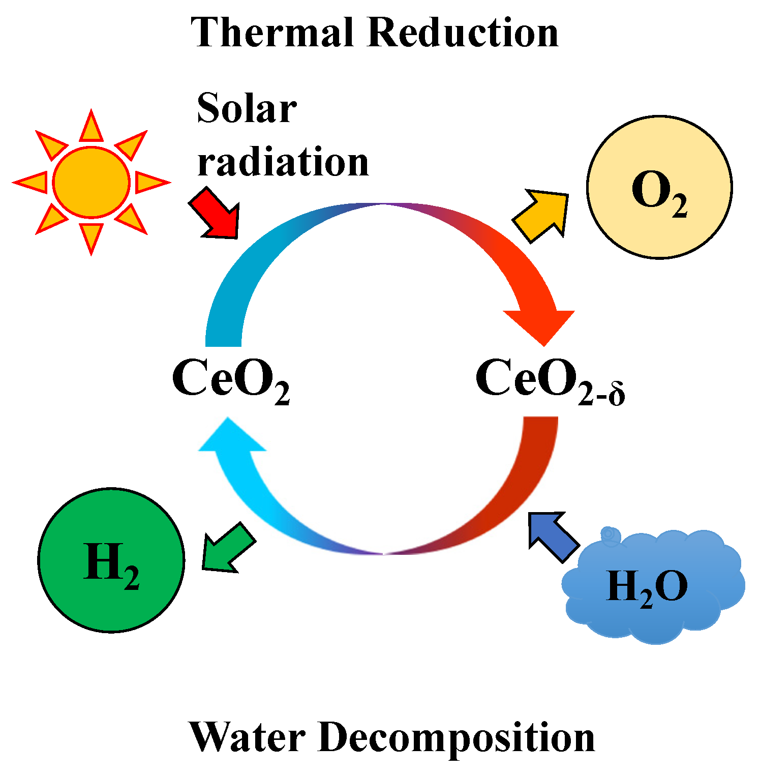
The thermochemical two-step water-splitting cycle system is an attractive method to produce hydrogen via the dissociation of water. Due to the inexhaustible magnitude and usability of solar energy, the solar-driven two-step water-splitting thermochemical cycle is generally considered a solution for hydrogen production from water [1]. Among the various metal oxides or redox materials, Fe3O4/FeO system was suggested by Nakamura (1977), who conducted thermodynamic analyses on the possibility of a two-step water-splitting cycle for oxygen/hydrogen production [2,3]. Then, other redox materials, such as NiFe2O4, ZnO/Zn, and CeO2, were proved to suitable materials for a solar-driven two-step H2O/CO2-splitting cycle for solar fuel production [4,5,6,7,8,9,10]. Recently, CeO2 (cerium oxide) had received considerable attention as a potential reactive metal oxide for a two-step water splitting-cycle and has reported higher oxygen/hydrogen productivity due to its higher reaction kinetics. Figure 1 describes a schematic diagram of a non-stochiometric CeO2/CeO2-δ thermochemical two-step water-splitting cycle reaction that utilize solar energy to produce oxygen and hydrogen. The two-step water-splitting cycle can be explained using the two equations below, where Equation (1) is for the thermal reduction step for oxygen evolved from CeO2, and Equation (2) is the subsequent water decomposition step, where the reduced CeO2-δ is oxidized and returns to its original state. The reactivity of CeO2 has been reported in the literature using the micron and grams scale of powder test, pellet block, reticulated structure, and granule particles with a fluidizing type bed reactor [11,12,13,14,15,16].
CeO2 → CeO2-δ + δ/2O2
CeO2-δ + δH2O → CeO2 + δH2
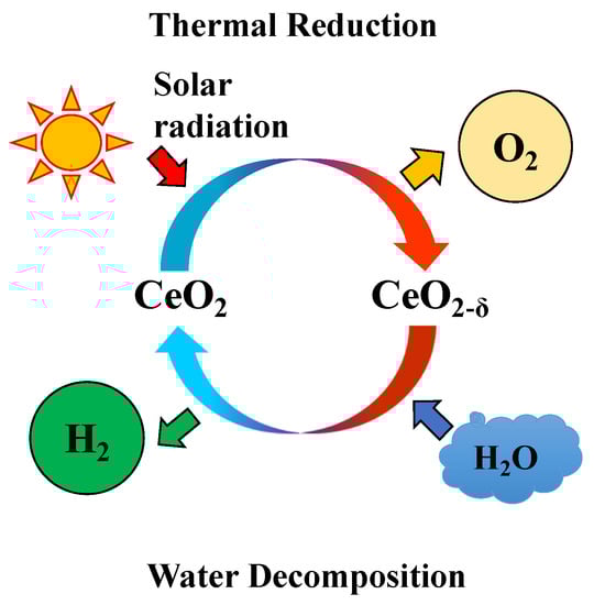
Figure 1.
Schematic diagram of solar-driven thermochemical two-step water-splitting cycle from non-stoichiometric ceria.
The effective thermal reduction temperature of CeO2 to split up the O2 from CeO2 lattice is high (up to 1500 °C), it continues to be a hurdle in the design of solar reactors and their operations. Currently, research on the CeO2/Ce2O3 system cycle has moved toward performing the thermal reduction step at temperatures below the melting temperature of CeO2/Ce2O3 and promoting oxygen and hydrogen production performances by doping CeO2 with other elements. In order to decline of temperature for thermal reduction and improve the reactivity, the substitution of a different material in CeO2, such as iron, manganese, cobalt, and zirconia (Fe, Mn, Co, and Zr) etc., has been tested to promote oxygen/hydrogen productivity [17]. In earlier researches of doped-ceria cycles, alkaline earths (e.g., calcium or strontium; Ca or Sr), other elements (e.g., zirconia or aluminium; Zr or Al), transition elements (e.g., manganese, iron, cobalt, nickel and copper; Mn, Fe, Co, Ni, or Cu) [18], and lanthanides (e.g., lanthanum, praseodymium, samarium, gadolinium, or terbium; La, Pr, Sm, Gd, or Tb) [19,20,21] have been investigated for their thermochemical cycles [17,22,23,24].
However, most reported literature focused on the powder scale and tested using smaller scales. In this study, a multivalent cation Mn was selected to improve hydrogen productivity for a M-CeO2 (M is the dopant material) foam device using two different synthesis and coating methods. One is the coprecipitation method for the synthesis of 5 mol% and 15 mol% of Mn-CeO2 powder with three different particle size ranges, and the application of the spin coating method for the fabrication of reactive Mn-CeO2 foam devices. The other one method is a newly developed direct deposition method where the doping and coating processes are conducted simultaneously, for the fabrication of 5 mol% and 15 mmol% Mn-CeO2 foam devices. For comparison of the reactivity, a pristine CeO2-coated foam device was also prepared. All prepared sample devices were evaluated using five cyclic tests of a two-step water-splitting cycle with a 3-kWth artificial sun-simulator. The experimental condition of the thermal reduction temperature was 1400 °C over 45 min, and then the water decomposition step was 1200 °C for 60 min. After the five cyclic tests, the oxygen and hydrogen productivity were compared and discussed.
2. Materials and Methods
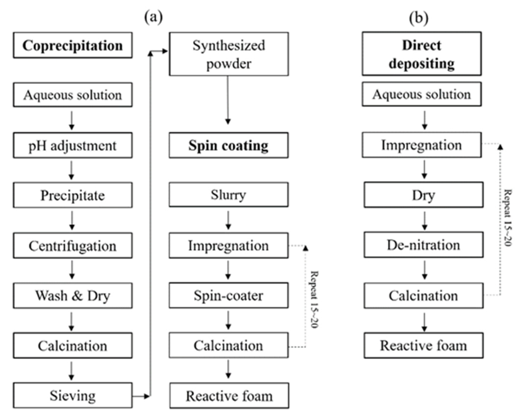
The reactive foam device samples for the two-step water-splitting cycle for oxygen/hydrogen productivity estimation were fabricated using two different methods. The first was the synthesis of Mn-CeO2 powder via a coprecipitation method, and then coating onto a disk-type porous foam (MgO partially stabilized zirconia, MPSZ) using a spin coating process. The other method was a direct depositing method, which contemporaneous synthesizes and coats the Mn-CeO2 foam device.
Figure 2 shows a schematic diagram of coprecipitation synthesis with the subsequent spin coating process in Figure 2a, and direct depositing process for synthesis and fabrication of Mn-CeO2 coated reactive foam device in Figure 2b.

Figure 2.
Schematic diagram of synthesis of Mn-CeO2 and fabrication of Mn-CeO2 coated foam devices: (a) synthesized by coprecipitation method and spin coating process, (b) direct depositing method.
In terms of the foam support matrix for coating the reactive Mn-CeO2, this study decided to use magnesium partially stabilized ZrO2 (MPSZ) (product model of Foseco Japan Ltd.) rather than SiSiC or SiC based support, which have been used by other researchers as a solar irradiations absorber or as a redox metal oxide support matrix, as MPSZ has higher quality with regard to heat resistance ability and resistance to chemical corrosion [7,8,25,26]. The CeO2/Mn-CeO2 foam device made using the coprecipitation method combine with the spin coating process and then a direct depositing method on MPSZ foam matrix was fabricated using different powder sizes and extents of Mn doping.
The coprecipitation method with a spin coating process needs two separated processes. First, the synthesis of Mn-CeO2 powder and then a milling and sieving process. After preparation of the Mn-CeO2 powder, an aqueous slurry needs to be made for the spin-coating process. During the spin-coating process of synthesized Mn-CeO2 on to foam, there are significant losses of synthesized Mn-CeO2 powder. This synthesis and coating process consumes a great deal of time for the preparation/fabrication of the Mn-CeO2-coated reactive foam device.
On the other hand, the direct depositing method has the advantage of a rapid fabrication time and is lossless for Mn-CeO2. The doping and coating processes are conducted simultaneously, which can save time in terms of fabrication, and does not lose reactive materials. In addition, by the third stage of the dry and calcination temperature program, the residual nitrate (NO3−) in the solution can be effectively removed, and a homogenous coat surface can be achieved. The detailed steps for each synthesis and coating process are explained in the following sections.
2.1. Pristine CeO2 Foam Device Using a Spin-Coating Method
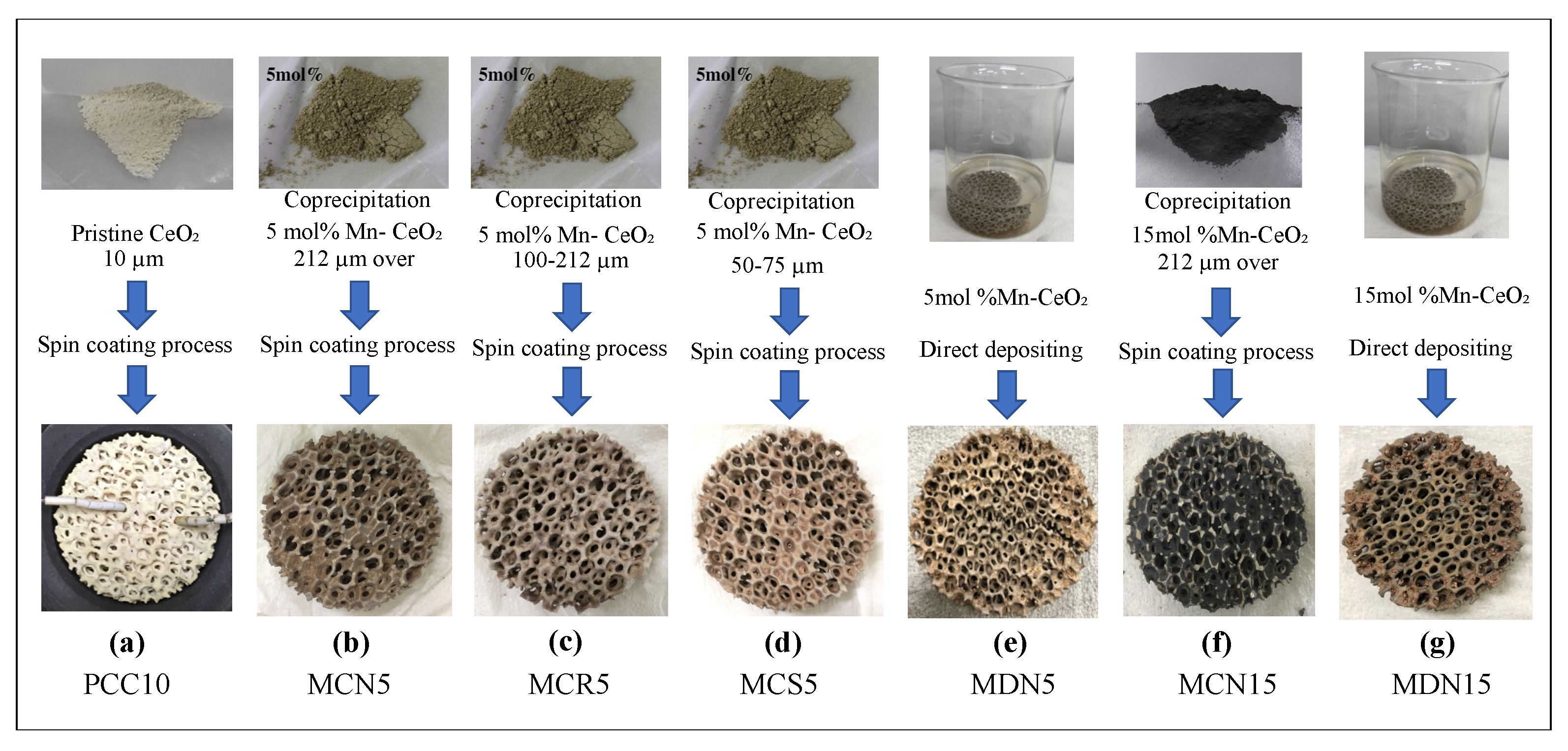
Figure 3 and Table 1 show all devices that were fabricated and tested in this study, and are categorized according to synthesis method and particle size. Sample (a) is a photograph of a pristine-CeO2-coated foam device. In order to estimation the oxygen and hydrogen production performance of the several prepared Mn-CeO2-coated foam devices, a pristine CeO2-coated foam device was also fabricated. The pristine ceria powder (99.9% purity, 10 μm) was ordered and obtained from Kojundo Chemical Laboratory Co., Ltd. (Saitama, Japan). The ceria-containing slurry was composed of 10 g of pristine CeO2 powder, 33 mL of chemically-purified water, 0.1 g of sodium polyacrylate (as a role of dispersant), and 0.1 g of acrylic resin (as a role of binder). The shape of foam matrix had a diameter of 60 mm (mm.), a thickness of 15 mm., and a pore/cell size of 10 cpi (cell number per linear inch). The impregnating wet process was conducted under reduced pressure in order to eliminate the air bubbles remained in the foam/pores and to induce homogeneous surface coating of the MPSZ foam. The sufficiently wet MPSZ foam was placed in a spin coater and rotated at 150 rpm for 1 min, in order to purge the unnecessary excess slurry from the foam pores to avoid clogging. After rotation, the foam was heated to 1200 °C for the calcination process for 60 min in air stream [26]. These steps of spin coating process for preparation of pristine CeO2 coated foam device were repeated approximately 15–20 times. The loading amount of pristine CeO2 was measured and confirmed from the weight difference, before and after loading. The final loaded amount of pristine CeO2 was recorded at 30 weight percent (wt%).
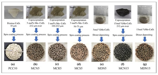
Figure 3.
Photograph of CeO2/Mn-CeO2 powder samples and reactive CeO2/Mn-CeO2 coated foam devices. (a) Pristine CeO2 spin-coated foam device (PCC10); (b) co-precipitation with 5 mol% Mn-CeO2 spin-coated foam device with over 212-µm powder size (MCN5); (c) co-precipitation with 5 mol% Mn-CeO2 spin-coated foam device with powder size of 100–212 µm (MCR5); (d) co-precipitation with 5 mol% Mn-CeO2 spin-coated foam device with powder size of 50–75 µm (MCS5); (e) direct deposition of 5 mol% Mn-CeO2 foam device (MDN5); (f) co-precipitation with 55 mol% Mn-CeO2 spin-coated foam device with over 212-µm powder size (MCN15); and (g) direct deposition of 15 mol% Mn-CeO2 foam device (MDN15).

Table 1.
Sample names and specifications of synthesis method, dopant extent, particle size, and weight percent of the seven prepared foam devices.
2.2. Coprecipitation Method and Spin-Coating Method for Mn-CeO2 Foam Device
The samples (b, c, d, and f) in Figure 3, which are Mn-doped CeO2-powder-coated foam devices, were synthesized using a wet impregnation process with involving co-precipitation method of the precursor by a complexed aqueous solution of Ce(NO3)3·6H2O (purity 98.0%) and Mn(NO3)2·6H2O (purity 98.0%). These materials were purchased from Wako Pure Chemical Industries, Ltd. (http://www.wako-chem.co.jp (accessed on 15 May 2018). Chemically-purified water which free of O2, CO2, and impurities was prepared by passing N2 gas through purified water for a few hours. The above listed reagents were dissolved in purified water at appropriate concentrations. The potential of hydrogen (pH) of each aqueous solution was adjusted to 8.5 by adding 0.15 mol dm−3 NaOH solution, therefore, resulted in the formation of the precursor. After heating the aqueous solution to 65 °C, air was bubbled into the suspension for 2 h while the pH was maintained at 8.5 via continuous addition of NaOH solution. The synthesized solid grains were collected via centrifugation machine at 3000 rpm (KS-4000, Kubota), washed with purified water with acetone. After the washing the synthesized Mn-CeO2 grain powder, it dried under vacuum at 100 °C for 1 day. Then the synthesized Mn-CeO2 grain powders were calcined at 900 °C for 2 h under air, before implement the high-temperature cyclic reactions [17]. After the synthesis of the Mn-CeO2 grain powder, it was hand milled and sieved using three different size levels: over 212 μm, 100–212 μm, and 50–75 μm, for comparing the coating surfaces. Then, the spin-coating method was implemented to coat the foam devices in the same manner as the pristine CeO2 coated foam device preparation process. The degree of transition element dopants were set to 5, 15 mol% of the total (dopant + cerium) metal content when the Mn-doped CeO2 was synthesized using the co-precipitation method. All devices were loaded with Mn-CeO2 up to 30 wt% as with the prepared pristine CeO2 foam device.
2.3. Direct Depositing Method for Mn-CeO2 Foam Device
Samples (e, g) were Mn-doped CeO2 powder-coated foam device, which were synthesized and coated using a direct depositing method. The uncoated MPSZ foam matrix was impregnated with a complexed aqueous solution of Ce(NO3)3·6H2O (purity 98.0%), Mn(NO3)2·6H2O (purity 98.0%) with purified water. After impregnation for 1 min, the wet foam device was dried from electric furnace at 120 °C for 3 h under air. Then, it was heated to 400 °C for 3 h in order to eliminate the remained NO3− phase. At the last step, the direct doped Mn-CeO2 foam device was calcinated at 1200 °C for 1 h under air. The impregnation to calcination process was repeated 15~20 times same as spin coating method for 30 wt% coating weight percent. The direct depositing method has the advantage of no necessary of a neutralization process because sodium hydroxide (NaOH) is not involved to the synthesis process. The magnitude of Mn dopant were set to 5, 15 mol% of the total (manganese + cerium) content which was the same as the co-precipitation method, in order to compare the reactivity. All devices were loaded with Mn-CeO2 up to 30 wt%, which was the same as the other prepared foam devices. Approximately, the fabrication time of the foam device using the direct deposition method need only one third the time compared to the co-precipitation and spin coating method. Furthermore, there was no loss of synthesized materials during the reactive foam device fabrication process.
2.4. XRD Results of the Synthesized 5, 15 mol% Mn-CeO2 Materials
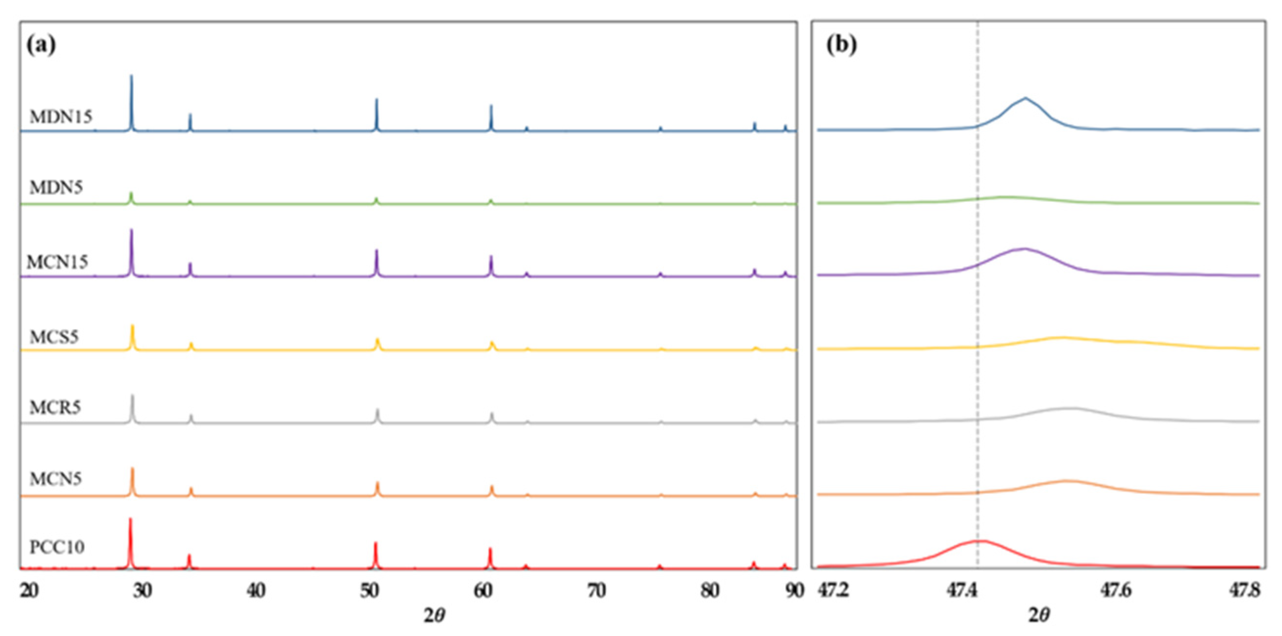
Figure 4 shows XRD (X-ray powder diffraction with CuKa radiation, MXeLabo, MAC Science) patterns of each original Mn-CeO2 material synthesized via the co-precipitation method and direct depositing method, 5, 15 mol%, and of the pristine CeO2, for comparison. In the Figure 4a, a series of peaks due to the fluorite structure were apparent from all seven samples. No new peak points by the Mn doping were recorded. This result means that the 5 and 15 mol% Mn-doped CeO2 maintains the fluorite structure of the cerium-based oxide as a single phase, indicating that the Mn additions were incorporated into the crystal structure as a solid solution [17].
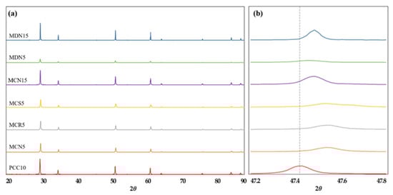
Figure 4.
XRD pattern of all prepared foam devices: (a) XRD pattern for the range of (2θ = 20–90°) and (b) expanded range of (2θ = 47.2–47.8°) which showing the peak shift toward higher diffraction angle by the incorporation of Mn into CeO2.
Further, in the 2θ = 47.2–47.8° range in Figure 4b, the XRD peaks for 5 and 15 mol% Mn–CeO2 were shifted toward higher diffraction angle, comparing to the original CeO2 peak. This peak shift supports the incorporation of Mn ions into the CeO2 with a fluorite type structure during both synthesis process. In the case of MCN5, MCR5, MCS5, and MDN5 sample, which synthesized to 5 mol% Mn-CeO2, shows smooth peak height than MCN15 and MDN15 which synthesized to 15 mol% Mn-CeO2.
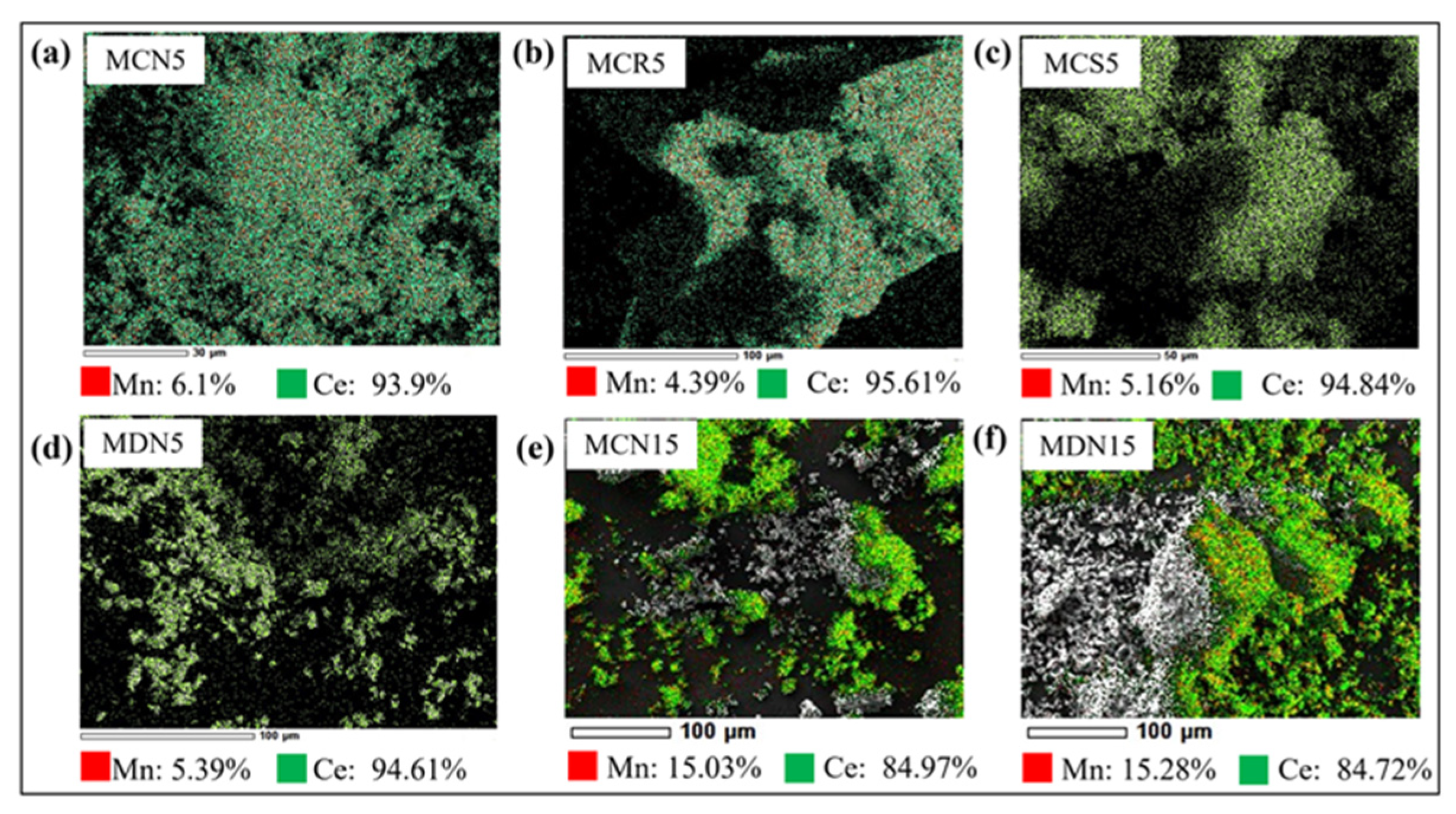
2.5. SEM/EDS Analysis for Verifying Mn-CeO2 Materials
Figure 5 shows the analysis result of scanning electron microscopy/energy dispersive X-ray spectroscopy (SEM/EDS, JCM-6000 NeoScope) for 5 and 15 mol% Mn-CeO2 coated foam devices: (a) MCN5, (b) MDN15, (c) MCS5, (d) MDN5, (e) MCN15, and (f) MDN15 for validation of Mn content. The measurement was implemented 3 times for one sample foam device surface, the Mn, and Ce content percent were estimated by the average value. From Figure 5a–d, which the 5mol% Mn-CeO2 designed cases shows the content value of 4.39~6.1% for Mn, and 93.9~95.61% for Ce. In comparison, the case of Figure 5e,f, which MCN15 and MDN15 (15mol% Mn-CeO2) show the content value of 15.03% and 15.28% for Mn, and 84.97% and 84.72% for Ce. It shows that the both synthesis and coating process are having good reliability for fabrication of Mn-CeO2 coated foam device for applying the two-step water splitting cycle solar reactor.
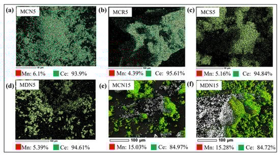
Figure 5.
Analysis of scanning electron microscopy(SEM)/energy dispersive X-ray spectroscopy (EDS) of synthesized (a) MCN5, (b) MDN15, (c) MCS5, (d) MDN5, (e) MCN15, and (f) MDN15.
3. Experimental Setup
Figure 6 describes the experimental setup of the solar reactor for carrying out the two-step water-splitting cycle using CeO2/Mn-CeO2 foam devices. The solar reactor body was made of SUS310S material, which served as the continuous two-step reactor and as a support for the foam devices. The prepared reactive foam devices were placed in the center of the reactor interior, which was exposed to concentrated solar irradiation via a transparent quartz window. There were three inlets in the device’s side, and one outlet on the bottom of foam device center. The temperature of the tested reactive foam device was measured using a B-type thermocouple at the center of foam device surface (Tcenter) and a K-type thermocouple at the side of foam device (Tside) [26]. Two thermocouples were installed in the pores of the center and side of foam device in order to measure the foam device’s exact temperature and to avoid direct exposure to incident irradiated light.
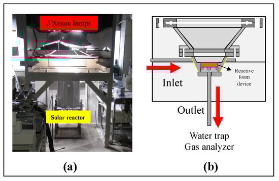
Figure 6.
(a) Photograph of a 3 kWth sun-simulator. (b) Schematic diagram of solar reactor with a reactive foam device for the two-step water-splitting cycle.
In this series of foam device reactivity performance experiments, the two-step water-splitting cycle was performed via sun-simulator irradiations with preheating of the reactive foam device. Before starting the thermal reduction (T-R) step, the intensity of irradiated light from the lamps of the sun-simulator was controlled to linearly heat up the foam device. Figure 6a shows the solar reactor involving reactive foam device and located to below three 6-kW Xe-arc 3 lamps of the sun-simulator (SFS-6003A, Nihon Koki), aligned with the axis of the oval concentrator of the sun-simulator. The parabolic reflection surfaces in the sun-simulator reflected the Xe-lamp lights downwards onto the focal spot. The reactive foam device in the solar reactor was set on the focal spot of concentrated irradiation. The diameter of the irradiation concentrated focal spot was measure to 6 cm. Furthermore, the flux intensity of the irradiation was previously measured using a circular-foil gauge type heat flux sensor (64–1000-20/SW-1C-150, Medtherm), which offered a power of 3 kWth [8].
The pre-heating temperature was raised from ambient temperature to 1000 °C over 45 min with a flow of 1.5 dm3/min for the N2 (purity: 99.999%) gas stream. The temperature was controlled using a lamp power controller. After the pre-heating step, the concentrated Xe-light irradiation was increased to 1400 °C, with the N2 gas stream being injected from the 3 holes of foam device at 2 dm3/min to operate the T-R step. The temperature of the foam device (Tcenter) was aimed to 1400 °C during the T-R step by monitoring the B-type thermocouple in the foam device center. The T-R step was continued for 45 min of oxygen evolution and release to out of reactor. After the T-R step, the intensity of irradiation of the sun-simulator was adjusted to 1200 °C, and the gas stream suppling into the solar reactor was switched from N2 gas to a H2O/N2 gas mixture for the W-D step. The H2O/N2 gas mixture was prepared as follows: purified liquid water was supplied to an electric heat type spiral steam generator using a positive displacement type peristaltic(roller) pump at a constant rate of 4 cc/min to generate steam. By the combine steam pipeline and carrier N2 gas line at 1 dm3/min, the generated steam/N2 mixture was injected into the solar reactor. The reduced reactive foam device was subjected to steam/N2 gas mixture for 60 min for hydrogen production. The temperature of the foam device during operate the W-D step was keep to 1200 °C. The T-R step and subsequent W-D steps were alternately repeated 5 times. After the W-D step in each cycle, the hydrogen or steam mixture which remaining in the reactor interior were purged by passing carrier N2 gas through the solar reactor over 1 h. Table 2 explains the experimental operating conditions of each step, from pre-heating to the T-R step, W-D step, and purge step.
Table 2.
Experimental conditions of the two-step water-splitting cycle with reactive foam device using 3 kWth sun-simulator.
A sample amount of the effluent gas in the reactor outlet was passed through a capillary tube and entered a residual gas analyzer mass spectrometer (RG–102P, Ulvac, Inc., Chigasaki, Japan) in order to evaluate the O2/H2 magnitude in the product gases as well as the production rates of O2/H2. During the T-R/W-D steps, degree and changes of O2/H2 partial pressure in the product gases were recorded with reference to the reaction time, then the amounts of evolved/produced O2/H2 were determined from the profiles of the partial pressure of O2/H2. Complementally, the mass spectrometer system includes the standard O2/H2 gas reservoir that can supply a constant flow rate as a reference. The standard O2/H2 suppling gas reservoir was utilized to calibrate the relations between partial pressure and the O2/H2 evolved/produced magnitude or amount.
Additionally, a partial amount of the produced gas was sampled by syringe then hydrogen concentration in the produced gas was determined by gas chromatography analyzer (GC-8A, Shimadzu, Japan) using a thermal conductivity detector (TCD) and Molecular Sieve 5A. The amount of hydrogen which produced through the W-D step operating was determined by the concentration of hydrogen profile series in the sample gases.
4. Results and Discussion
The continuous cyclic test of the thermochemical two-step water-splitting cycle, with the CeO2/Mn-CeO2 coated reactive foam devices, was performed for each of the five cycles. During the T-R step, the center temperature of the foam device was set and kept to 1400 °C for 45 min, while the side temperature of the foam device was recorded to 1200 °C. After the T-R step, a subsequent W-D step was operated under the device center temperature at 1200 °C for 60 min while the side temperature was recorded to 1000 °C. As the concentrated irradiation from sun-simulator has a gaussian distribution, which is the heat flux intensity of the center zone being stronger than the annular side zone, the temperature difference (ΔT = Tcenter − Tside) between the center and side of foam device was monitored during all cyclic tests. In order to define the amount of evolved oxygen from the T-R step, and the produced hydrogen amount from the W-D step these were measured and analyzed using a mass spectrometer and gas chromatography.
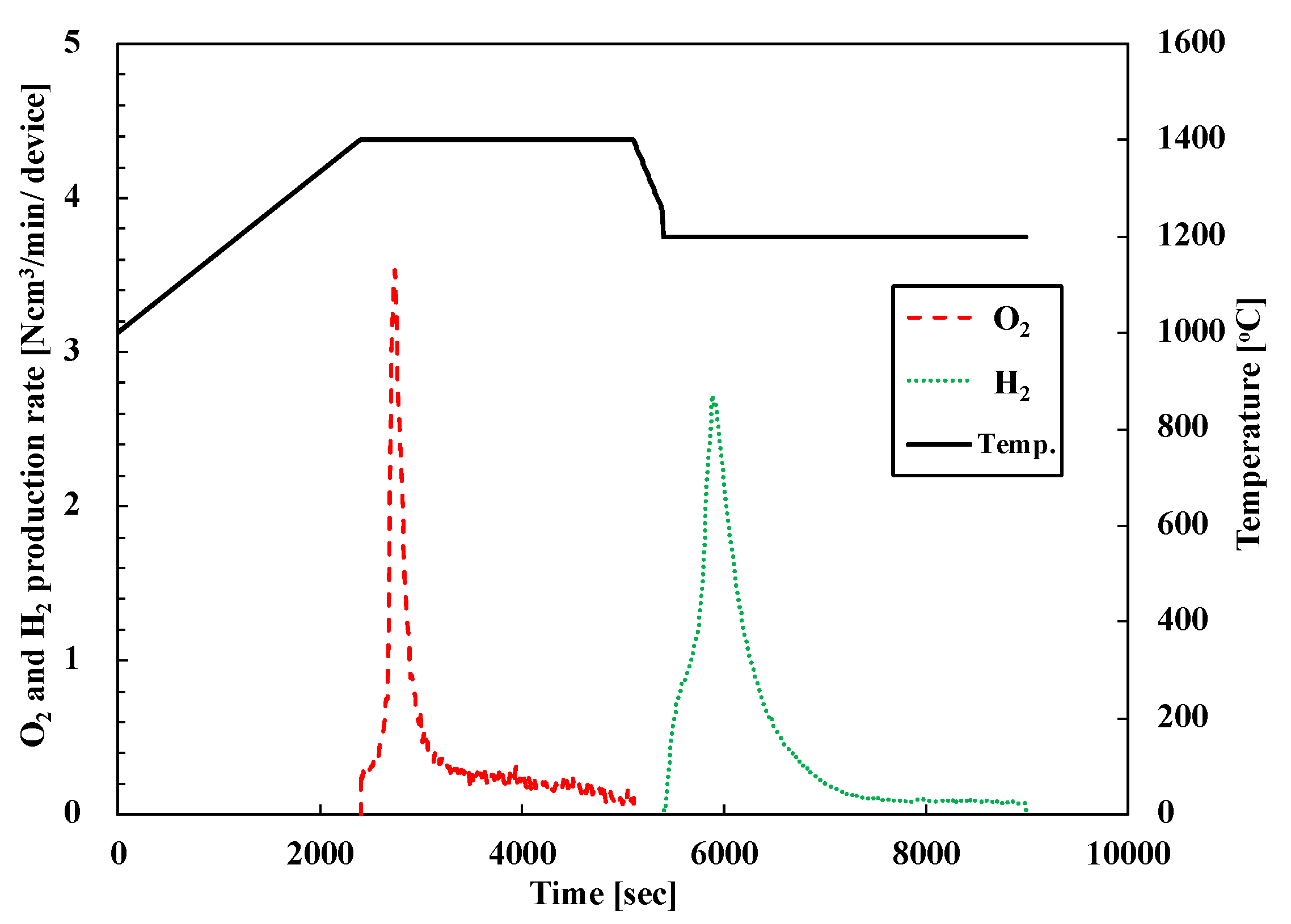
Figure 7 shows the O2/H2 production rate of representative PCC10 (pristine CeO2 foam device) for the first cycle. The black lines indicate the device center temperature and the dotted line indicate the oxygen (red) and hydrogen (green) production rates. Hydrogen production from the PCC10 foam device was successfully performed via a two-step water-splitting cycle with a 3-kWth sun-simulator. After starting the T-R step, the oxygen was evolved rapidly for 10 min, and then, the production rate was gradually reduced. Then, in the course of the W-D step, hydrogen was produced rapidly 15 min via the oxidation of the reduced PCC10 foam device and continued for 45 min. The produced amount of oxygen was 43.1 Ncm3 and hydrogen was 58 Ncm3 for the first cycle.
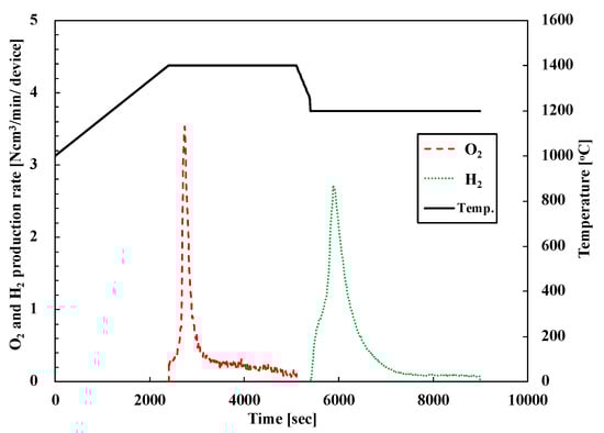
Figure 7.
O2 and H2 evolution profiles of two-step water-splitting cycle of pristine CeO2 foam device (PCC10) in the first cycle.
All seven of the prepared foam devices were tested for five cycles using the same sequence as the PCC10′s first cycle. Each cycle’s results are summarized in Table 3. Table 3 shows O2/H2 production amounts for each cycle, the total production amount of five cycles, the average amount of five cycles, and the H2/O2 ratio; it can be discussed in terms of the reactivity and production performance of the tested all reactive foam devices.
Table 3.
Experimental result of five cyclic tests, total production amount, and average production amounts for oxygen and hydrogen.
4.1. Comparison of Oxygen/Hydrogen Total Production Amount
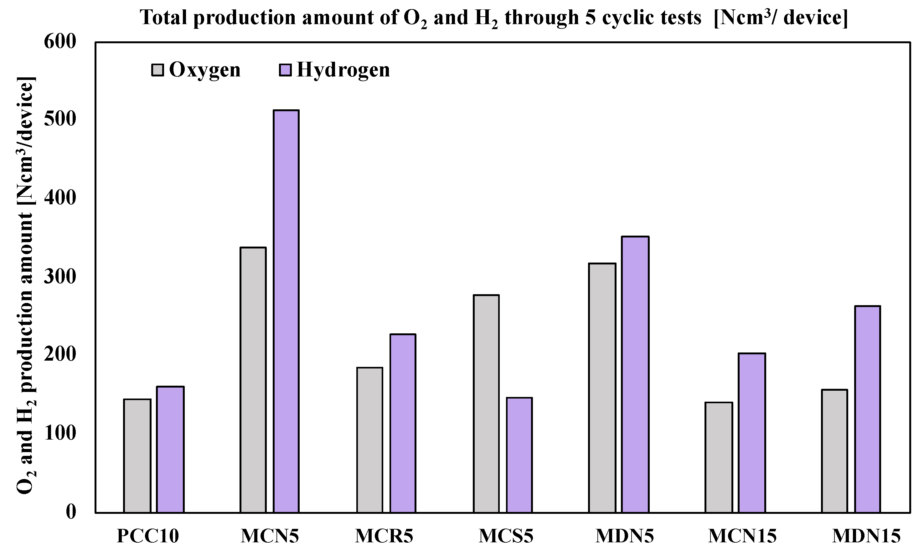
After the five cyclic tests of the seven prepared foam devices, the productivity of oxygen and hydrogen was compared. Figure 8 shows a graph of the total production amount. According to the total oxygen production amount, it was recorded in the order of MCN5 > MDN5 > MCS5 > MCR5 > MDN15 > PCC10 > MCN15. Among the seven foam devices, the largest amount of oxygen was recorded from MCN5 (5 mol% Mn-CeO2-Coprecipitation method, over 212 μm) at an amount of 338.1 Ncm3 for five cycles. This was 2.34-times greater than PCC10 (pristine CeO2 foam device) with a T-R step at 1400 °C/W-D step at 1200 °C. Almost all the Mn-CeO2 foam devices recorded a higher total oxygen production amount than PCC10, except for MCN15, which showed a positive effect of Mn ion doping into CeO2 to enhance the oxygen productivity for both the synthesis and coating methods.
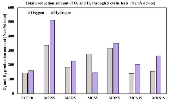
Figure 8.
Total production amount of O2 and H2 through 5 cyclic tests (Ncm3/device).
In terms of hydrogen productivity, the total hydrogen production amount was recorded in the order of MCN5 > MDN5 > MDN15 > MCR5 > MCN15 > PCC10 > MCS5. The largest amount of hydrogen was recorded from MCN5 (5 mol% Mn-CeO2-co-precipitation method, over 212 μm) at an amount of 513.1 Ncm3 for five cycles. This was 3.17-times greater than PCC10 (pristine CeO2 foam device). Almost all Mn-CeO2 foam devices recorded a higher total oxygen production amount than PCC10, except for MCS5, which showed the positive effects of Mn ion doping into CeO2 to enhance the hydrogen productivity also for both the synthesis and coating methods.
Only comparing 5 mol% Mn-CeO2 foam devices, the order of oxygen amounts was MCN5 > MDN5 > MCS5 > MCR5, and the hydrogen amounts were MCN5 > MDN5 > MCR5 > MCS5. MCN5, which was the 5 mol% Mn-CeO2-co-precipitation method (over 212 μm), showed the greatest oxygen and hydrogen production amounts. The second largest oxygen and hydrogen amounts were recorded from MDN5 (5 mol% Mn-CeO2-direct depositing method), which showed higher reactivity than MCR5 and MCS5 that were synthesized using the co-precipitation method and spin coating.
In addition, for the case of 15 mol% Mn-CeO2 foam devices (MCN15 and MCN15), the results showed that MDN15 recorded a higher productivity of oxygen and hydrogen than MCN15. This result showed that the newly developed direct depositing method was effective for the fabrication of Mn-CeO2 coated foam devices for two-step water-splitting cycles.
Generally, the uniformity of the coating surface was established from smaller particle sizes. Via SEM image analysis, the order of uniformity of the coating surfaces was MCS5 > MDN5 > MCR5 > MCN5 among the 5 mol% Mn-CeO2 foam devices. However, the highest oxygen and hydrogen amounts was recorded from MCN5, which was coated by largest particle size. Among the three different particle sizes of MCN5, MCR5, and MCS5, the results showed that the larger particle size was effective for the reactivity of 5 mol% Mn-CeO2 co-precipitation spin-coating cases.
4.2. Comparison of Oxygen/Hydrogen Average Productivity and Cyclicity
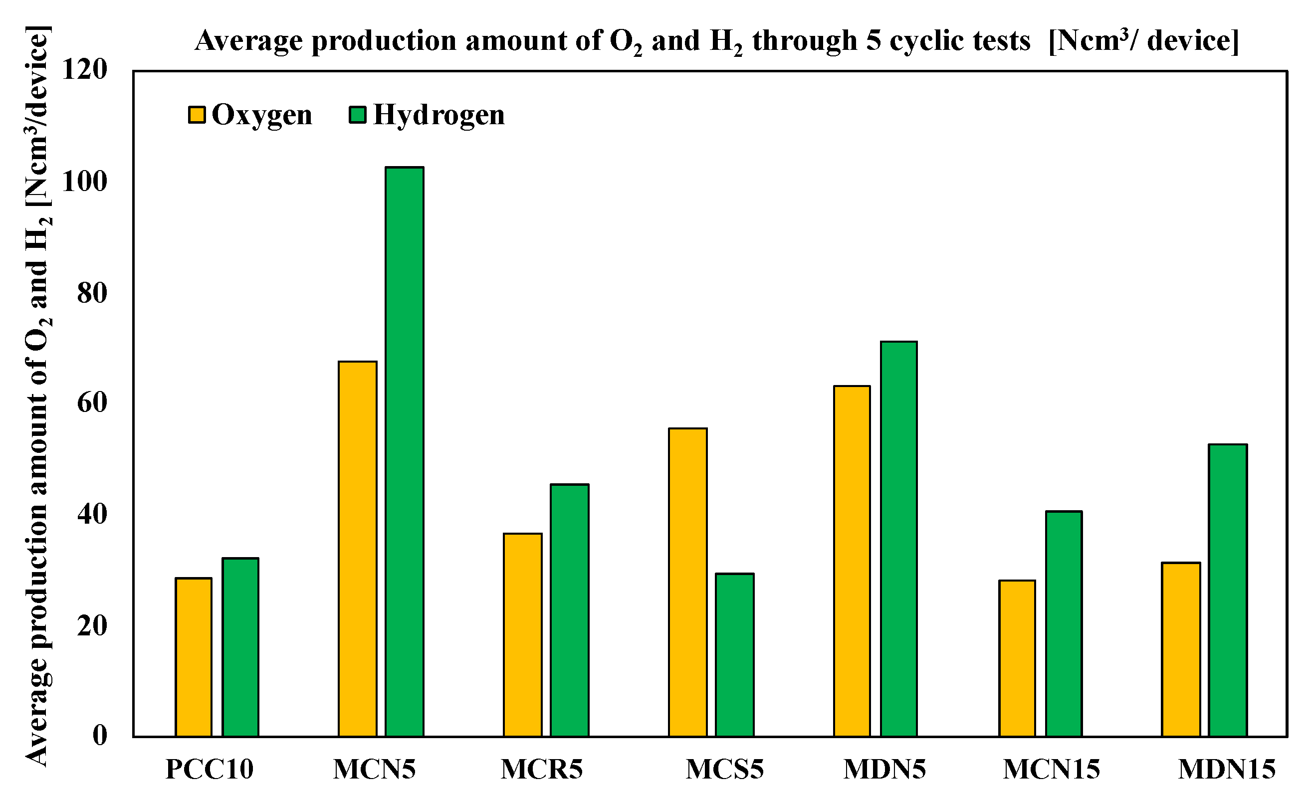
Figure 9 shows the average oxygen and hydrogen production amounts of the tested samples. According to average product amounts, the oxygen amounts were in the order of MCN5 > MDN5 > MCS5 > MCR5 > MDN15 > MCN15 > PCC10 and the hydrogen amounts were in the order of MCN5 > MDN5 > MDN15 > MCR5 > MCN15 > PCC10 > MCS5; which was the same as the total production amount order. The H2/O2 ratios of the samples are compared and described in the Table 3. The highest ratio was recorded from MDN15 at 1.68 and the order of all samples was MDN15 > MCN5 > MCN15 > MCR5 > PCC10 > MDN5 > MCS5. The ideal stoichiometric ratio of H2/O2 for ceria-based water splitting cycle reaction among the samples, was for MDN15 which showed the nearest value to the stoichiometric reaction ratio.
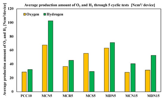
Figure 9.
Average production amount of O2 and H2 through 5 cyclic tests (Ncm3/device).
The amount of Mn content in the Mn-CeO2 for both the co-precipitation and spin coating methods and the direct depositing method was 5 mol% Mn-CeO2 and showed higher oxygen and hydrogen productivity compared with MCN5 vs. MCN15 and MCN15 vs. MDN15. This explains that the 5 mol% of Mn-CeO2 was a more effective foam device for the water-splitting cycle than 15 mol% Mn-CeO2 with a T-R-step temperature range of 1400 °C and W-D step of 1200 °C. This is a new and different report compared with other literature that has studied powder scale.
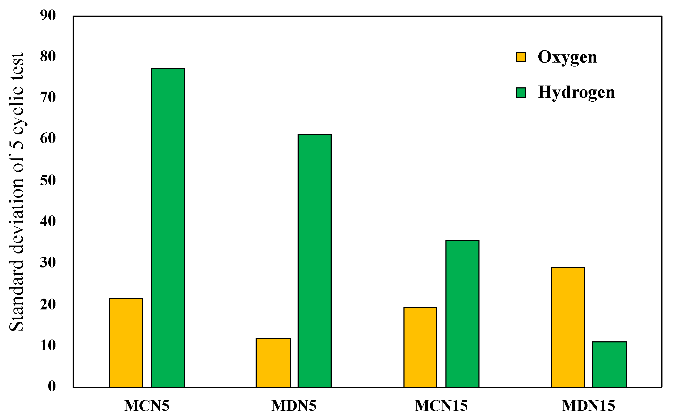
During the five cyclic tests, the oxygen and hydrogen production amounts showed a gradual decrease due to surface coating degradation. After the five cyclic tests of all prepared devices, the standard deviation from the first to the fifth cycle of the representative four devices, MCN5, MDN5, MCN15 and MDN15, was compared.
Figure 10 shows the standard deviation from the first to the fifth cycle for estimation of the stable reactivity through five cycles. The results shows that MCN15 and MDN15, which are 15 mol% Mn-CeO2 foam devices, recorded lower values than the MCN5 and MDN5 samples. The higher Mn doping extent resulted in a higher stable reactivity. In term of comparison of the synthesis methods, which were co-precipitation method samples versus direct depositing method samples (MC series vs. MD series), the direct depositing method samples recorded lower standard deviation values in both 5 and 15 mol% Mn-CeO2 foam devices. When considering the relationship between the standard deviation of oxygen and hydrogen, there is no significant relation in these results.

Figure 10.
Standard deviation of four representative 5 and 15 mol% Mn-CeO2 foam devices for oxygen and hydrogen.
According to this result, the direct depositing method for the synthesis of Mn-CeO2 and coating on a foam matrix is a new and promising method for the fabrication of reactive foam devices for driving solar two-step water-splitting cycle hydrogen production at lower temperature ranges.
5. Conclusions
In order to develop a higher reactivity redox metal oxide coated reactive foam device for two-step water-splitting cycle hydrogen production, the synthesis of Mn-CeO2 materials and the coating processes were studied. The co-precipitation method was applied to fabricate three different particle size ranges (over 212 μm, 100–212 μm, and 50–75 μm) of 5 mol% Mn-CeO2, which were coated on a foam device using a spin-coating method. In addition, a higher Mn content version with 15 mol% Mn-CeO2 (over 212 μm) was also fabricated. On the other hand, a new direct depositing method which uses doping and coating processes was simultaneously conducted was used to fabricated 5 and 15 mol% Mn-CeO2 foam devices. All prepared devices tested oxygen and hydrogen productivity through five cyclic tests of the two-step water-splitting cycle with a temperature range in the T-R step of 1400 °C and W-D step at 1200 °C using a 3-kWth sun-simulator. All sample devices showed successful two-step water-splitting cycle hydrogen production, and the reactivity and cyclicity were compared.
- Almost all Mn-CeO2 foam devices recorded higher oxygen and hydrogen productivity.
- The order of oxygen production amounts through the five cycles was MCN5 > MDN5 > MCS5 > MCR5 > MDN15 > PCC10 > MCN15.
- The order of hydrogen production amounts through the five cycles was MCN5 > MDN5 > MDN15 > MCR5 > MCN15 > PCC10 > MCS5.
- MCN5 recorded the largest oxygen and hydrogen amounts among all tested sample devices.
- Among the three different size range samples, MCN5, MCR5, and MCS5, the larger particle size coated foam device, MCN5, recorded higher oxygen and hydrogen production amounts.
- In terms of Mn doping amounts, 5 mol% Mn-CeO2 foam devices, MCN5, MCR5, and MDN5, showed higher hydrogen production than 15 mol% Mn-CeO2 foam devices, MCN15 and MDN15.
- Regarding the cyclicity, the newly developed direct depositing method samples, MDN5 and MDN15, showed lower standard deviations for the five cycle results than coprecipitation and spin coated foam devices, which are MCN5 and MCN15.
- The newly suggested direct depositing method for Mn-CeO2 foam devices showed a rapid fabrication time by one third than co-precipitation and spin-coating methods and recorded successful oxygen and hydrogen production with lower standard deviations.
- However, the proposed synthesis method, fabricated and tested foam devices are still need to further investigations to improve the its stability from long-term cycle tests.
Author Contributions
Conceptualization, H.-S.C.; methodology, H.-S.C.; software, S.B.; validation, N.G., T.K. and H.-S.C.; formal analysis, H.-S.C., J.-K.K.; investigation, H.-S.C.; resources, H.-S.C., T.K.; data curation, H.-S.C.; writing—original draft preparation, H.-S.C.; writing—review and editing, H.-S.C.; visualization, H.-S.C.; supervision, H.-S.C.; project administration, T.K.; funding acquisition, T.K. All authors have read and agreed to the published version of the manuscript.
Funding
This research received no external funding.
Institutional Review Board Statement
Not applicable.
Informed Consent Statement
Not applicable.
Conflicts of Interest
The authors declare no conflict of interest.
References
- Ghoniem, A.F. Needs, resources and climate change: Clean and efficient conversion technologies. Prog. Energy Combust. Sci. 2011, 37, 15–51. [Google Scholar] [CrossRef]
- Nakamura, T. Hydrogen production from water utilizing solar heat at high temperatures. Sol. Energy 1977, 19, 467–475. [Google Scholar] [CrossRef]
- Kodama, T.; Gokon, N. Thermochemical cycles for high-temperature solar hydrogen production. Chem. Rev. 2007, 107, 4048–4077. [Google Scholar] [CrossRef]
- Kaneko, H.; Taku, S.; Tamaura, Y. Reduction reactivity of CeO2-ZrO2 oxide under high O2 partial pressure in two-step water splitting process. Sol. Energy 2011, 85, 2321–2330. [Google Scholar] [CrossRef]
- Koepf, E.; Villasmil, W.; Meier, A. Pilot-scale solar reactor operation and characterization for fuel production via the Zn/ZnO thermochemical cycle. Appl. Energy 2016, 165, 1004–1023. [Google Scholar] [CrossRef]
- Abanades, S.; Charvin, P.; Flamant, G. Design and simulation of a solar chemical reactor for the thermal reduction of metal oxides: Case study of zinc oxide dissociation. Chem. Eng. Sci. 2007, 62, 6323–6333. [Google Scholar] [CrossRef]
- Müller, R.; Lipiński, W.; Steinfeld, A. Transient heat transfer in a directly-irradiated solar chemical reactor for the thermal dissociation of ZnO. Appl. Therm. Eng. 2008, 28, 524–531. [Google Scholar] [CrossRef]
- Gokon, N.; Murayama, H.; Nagasaki, A.; Kodama, T. Thermochemical two-step water splitting cycles by monoclinic ZrO2-supported NiFe2O4 and Fe3O4 powders and ceramic foam devices. Sol. Energy 2009, 83, 527–537. [Google Scholar] [CrossRef]
- Al-Shankiti, I.; Ehrhart, B.D.; Weimer, A.W. Isothermal redox for H2O and CO2 splitting—A review and perspective. Sol. Energy 2017, 156, 21–29. [Google Scholar] [CrossRef]
- Schieber, G.L.; Stechel, E.B.; Ambrosini, A.; Miller, J.E.; Loutzenhiser, P.G. H2O splitting via a two-step solar thermoelectrolytic cycle based on non-stoichiometric ceria redox reactions: Thermodynamic analysis. Int. J. Hydrogen Energy 2017, 42, 18785–18793. [Google Scholar] [CrossRef]
- Ackermann, S.; Sauvin, L.; Castiglioni, R.; Rupp, J.L.M.; Scheffe, J.R.; Steinfeld, A. Kinetics of CO2 Reduction over Nonstoichiometric Ceria. J. Phys. Chem. C 2015, 119, 16452–16461. [Google Scholar] [CrossRef] [PubMed] [Green Version]
- Scheffe, J.R.; Steinfeld, A. Oxygen exchange materials for solar thermochemical splitting of H2O and CO2: A review. Mater. Today 2014, 17, 341–348. [Google Scholar] [CrossRef]
- Jarrett, C.; Chueh, W.; Yuan, C.; Kawajiri, Y.; Sandhage, K.H.; Henry, A. Critical limitations on the efficiency of two-step thermochemical cycles. Sol. Energy 2016, 123, 57–73. [Google Scholar] [CrossRef]
- Lange, M.; Roeb, M.; Sattler, C.; Pitz-Paal, R. T-S diagram efficiency analysis of two-step thermochemical cycles for solar water splitting under various process conditions. Energy 2014, 67, 298–308. [Google Scholar] [CrossRef]
- Rudisill, S.G.; Venstrom, L.J.; Petkovich, N.D.; Quan, T.; Hein, N.; Boman, D.B.; Davidson, J.H.; Stein, A. Enhanced oxidation kinetics in thermochemical cycling of CeO2 through templated porosity. J. Phys. Chem. C 2013, 117, 1692–1700. [Google Scholar] [CrossRef]
- Kodama, T.; Bellan, S.; Gokon, N.; Cho, H.S. Particle reactors for solar thermochemical processes. Sol. Energy 2017, 156, 113–132. [Google Scholar] [CrossRef]
- Gokon, N.; Suda, T.; Kodama, T. Thermochemical reactivity of 5–15 mol% Fe, Co, Ni, Mn-doped cerium oxides in two-step water-splitting cycle for solar hydrogen production. Thermochim. Acta 2015, 617, 179–190. [Google Scholar] [CrossRef]
- Scheffe, J.R.; Steinfeld, A. Thermodynamic analysis of cerium-based oxides for solar thermochemical fuel production. Energy Fuels 2012, 26, 1928–1936. [Google Scholar] [CrossRef]
- Chueh, W.C.; Haile, S.M. Ceria as a thermochemical reaction medium for selectively generating syngas or methane from H2O and CO2. ChemSusChem 2009, 2, 735–739. [Google Scholar] [CrossRef] [Green Version]
- Zhou, G.; Gorte, R.J. Thermodynamic investigation of the redox properties for ceria–hafnia, ceria–terbia, and ceria–praseodymia solid solutions. J. Phys. Chem. B 2008, 112, 9869–9875. [Google Scholar] [CrossRef] [PubMed]
- Le Gal, A.; Abanades, S. Dopant incorporation in ceria for enhanced water-splitting activity during solar thermochemical hydrogen generation. J. Phys. Chem. C 2012, 116, 13516–13523. [Google Scholar] [CrossRef]
- Jiang, Q.; Zhou, G.; Jiang, Z.; Li, C. Thermochemical CO2 splitting reaction with Cex M1−xO2−δ (M = Ti4+, Sn4+, Hf4+, Zr4+, La3+, Y3+ and Sm3+) solid solutions. Sol. Energy 2014, 99, 55–66. [Google Scholar] [CrossRef]
- Kaneko, H.; Miura, T.; Ishihara, H.; Taku, S.; Yokoyama, T.; Nakajima, H.; Tamaura, Y. Reactive ceramics of CeO2–MOx (M= Mn, Fe, Ni, Cu) for H2 generation by two-step water splitting using concentrated solar thermal energy. Energy 2007, 32, 656–663. [Google Scholar] [CrossRef]
- Scheffe, J.R.; Weibel, D.; Steinfeld, A. Lanthanum–strontium–manganese perovskites as redox materials for solar thermochemical splitting of H2O and CO2. Energy Fuels 2013, 27, 4250–4257. [Google Scholar] [CrossRef]
- Cho, H.S.; Gokon, N.; Kodama, T.; Kang, Y.; Lee, H. Improved operation of solar reactor for two-step water-splitting H2 production by ceria-coated ceramic foam device. Int. J. Hydrogen Energy 2015, 40, 114–124. [Google Scholar] [CrossRef]
- Cho, H.-S.; Kodama, T.; Gokon, N.; Bellan, S.; Nishigata, N. Experimental Study of Mn-CeO2 Coated Ceramic Foam Device for Two-Step Water Splitting Cycle Hydrogen Production with 3kW Sun-Simulator. In Proceedings of the 25th SolarPACES, Daegu, Korea, 1–4 October 2019; Available online: https://aip.scitation.org/doi/10.1063/5.0029890 (accessed on 10 March 2021).

Publisher’s Note: MDPI stays neutral with regard to jurisdictional claims in published maps and institutional affiliations. |
© 2021 by the authors. Licensee MDPI, Basel, Switzerland. This article is an open access article distributed under the terms and conditions of the Creative Commons Attribution (CC BY) license (https://creativecommons.org/licenses/by/4.0/).