Article

Multi-Objective Decentralized Model Predictive Control for Inverter Air Conditioner Control of Indoor Temperature and Frequency Stabilization in Microgrid

by
Jonglak Pahasa
1,*,
Potejanasak Potejana
2 and
Issarachai Ngamroo
3
1
Department of Electrical Engineering, School of Engineering, University of Phayao, Phayao 56000, Thailand
2
Department of Industrial Engineering, School of Engineering, University of Phayao, Phayao 56000, Thailand
3
Department of Electrical Engineering, School of Engineering, King Mongkut’s Institute of Technology Ladkrabang, Bangkok 10520, Thailand
*
Author to whom correspondence should be addressed.
Energies 2021, 14(21), 6969; https://doi.org/10.3390/en14216969
Submission received: 29 September 2021 / Revised: 16 October 2021 / Accepted: 20 October 2021 / Published: 23 October 2021
(This article belongs to the Topic Power System Modeling and Control)

Abstract

:
Microgrid (MG) is a novel concept for a future distribution power system that enables renewable energy sources (RES). The intermittent RES, such as wind turbines and photovoltaic generators, can be connected to the MG via a power electronics inverter. However, the inverter interfaced RESs reduce the total inertia and damping properties of the traditional MG. Consequently, the system exhibits steeper frequency nadir and the rate of change of frequency (RoCoF), which may degrade the dynamic performance and cause the severe frequency fluctuation of the system. Smart loads such as inverter air conditioners (IACs) tend to be used for ancillary services in power systems. The power consumption of IACs can be regulated to suppress frequency fluctuation. Nevertheless, these IACs, regulating power, can cause the deviation of indoor temperature from the temperature setting. The variation in indoor temperature should be controlled to fulfill residential comfort. This paper proposes a multi-objective decentralized model predictive control (DMPC) for controlling the power consumption of IACs to reduce MG frequency fluctuation and control the variation in indoor temperature. Simulation results on the studied microgrid with the high penetration of wind and photovoltaic generator demonstrate that the proposed DMPC is able to regulate frequency deviation and control indoor temperature deviation as a user preference. In addition, the DMPC has a superior performance effect to the proportional-integral (PI) controller in terms of reducing frequency deviation, satisfying indoor temperature preferences, and being robust to the varying numbers of IACs.

1. Introduction

1.1. Motivation

Due to the considerable growth of renewable energy sources (RES) and distributed generations (DG), the concept of microgrid (MG) has become increasingly interesting worldwide [1,2,3]. The MG is generally referred to as a self-sustained small distribution power system comprised of loads, DG, and/or energy storage systems [3,4,5,6,7]. The MG can be operated in two modes, i.e., grid-connected or islanded modes [3,4,5,6,7,8]. The islanded operational mode of MG is significantly more challenging than the grid-connected mode because the voltage and frequency regulation of the MG is no longer dominated by the main grid [1,2,3,4,5]. The balance of power generation and loads in the MG is normally controlled by the microgrid central controller [1]. The DG, based on RES such as wind and photovoltaic (PV) generation, is conventionally connected to the MG by a power electronic inverter [9,10,11]. The capacity of installed inverter-based DG in power systems is rapidly growing [11]; however, the converter-interfaced DG to the power system causes the absence of rotational masses from synchronous generators (SGs), which leads to a lack of inertia and damping properties [9,11]. Consequently, the system exhibits steeper frequency nadir and the rate of change of frequency (RoCoF), which may degrade the dynamic performance, cause severe frequency deviation, and challenge the operation of sensitive equipment, such as protective relays in the grid [9,11]. The issue of low inertia has been reported to occur in various countries with high penetration of RESs. In September 2016, a black out occurred in South Australia due to the lack of inertia; the system could not accommodate rapid changes in frequency during sudden load imbalance [11].

1.2. Literature Review

In order to increase the inertial response of inverter-interfaced DG and improve frequency regulation, various techniques have been proposed in the literature [1,2,9,11]. The virtual synchronous generator (VSG) has been introduced as an effective solution for increasing system inertia [10]. The VSG mimics the behavior of conventional SGs in large power systems. VSG controllers have been designed, based on the swing equation, to imitate the static and dynamic characteristics of the SG [10]. However, the inertia emulator needs the conventional battery energy storage system (BESS) or other storage devices to inject power into the power system. Additionally, the BESS has been used for mitigating power fluctuation from RESs. Nevertheless, the poor life cycle of BESS has been identified as the key barrier of BESSs which hampers the development of the MG [8]. The controlling of DG-based RESs, such as wind and photovoltaic (PV) generation, has been proposed to suppress frequency deviation and increase the MG’s inertial response [10]. However, the controlling output power of wind and PV generators reduces the output power that the wind and PV can generate.
As explained above, the mismatch of power generation and load can be reduced by the generator side control. The studies of generator side controls for improving inertia of the inverter-based DGs have been studied by various researchers [1,2,3,8,11]. However, the ability of the generator side control may limit when the system operates against the severe frequency fluctuations. Therefore, controlling the power consumption of the controllable load is an interesting procedure to increase the inertia of the MG. The high penetration of RESs should have less effect on power system stability.
Recently, controllable loads, such as plug-in hybrid electric vehicles (PHEVs) [12] and air conditioners (ACs) [13,14,15,16,17,18,19,20,21] have been used to suppress frequency deviation. The PHEVs designed for traveling may not be appropriate for solving the severe frequency fluctuation of the MG. On the other hand, the increase in ambient temperature, remarkably, causes a high number of ACs in the power system [13,14,15,16,17,18,19,20,21]. The ACs are encouraged to act as a thermal battery for providing demand-side management [13,14,15], operating reserves [16], compensation for power fluctuations from the PV generator [17], and in primary frequency regulations (PFR) [18,19,20,21].
There are two types of ACs applying for PFR: the regular fixed frequency ACs and inverter ACs (IACs). The compressors of the regular ACs can only operate in two modes, i.e., on mode or off mode, while the compressors of the IACs can be adjusted continuously [20]. The on/off ACs for PFR work by turning on the ACs when the frequency is high, or the indoor temperature hits the maximum limit, and turning off the ACs when the frequency is low, or the indoor temperature hits the minimum limit [18,19]. However, the on/off switch ACs require the resetting of the indoor temperature to the nominal operating when the indoor temperature hits the minimum/maximum limit, which may not be appropriate to suppress severe frequency deviation. In any case, the IACs for PFR work by controlling the power consumption of IACs to suppress frequency deviation and maintain the indoor temperature as simultaneously defined [20,21]. The IACs have superior performance to the on/off ACs because the inverters of IACs can be controlled by frequency adjustment and temperature set-point changes. In [20], the IACs were used for the mitigating frequency oscillation of a multi-area interconnected power system. In [21], the coordinated control of IACs groups has been proposed. Nevertheless, in [20,21], the number of IACs participating in frequency regulation is constant for one day, and the control parameters are optimized, based on the fixed number of participating IACs. Nevertheless, when some IACs have accidentally stopped participation in PFR, the designed controller may deteriorate and may not successfully handle the PFR. Therefore, the controller designed for a variable number of IACs is expected.
Moreover, as proposed in [20,21], the IACs applied for PFR cause a slight temperature variation, which does not affect user comfort. Nevertheless, the preferable indoor temperature variation of each person/area is different, depending on the purpose for cooling the room or area. For example, a home living room tolerates a smaller temperature variation than a department store. In addition, based on the benefit of frequency ancillary services of smart loads for the low inertia power system explained in [22,23,24], the higher ability of the smart load for PFR can get a higher returned benefit to the owner. Therefore, the different indoor temperature range, which has a different ability to suppress frequency deviation, should result in the beneficial difference returned to the IACs owner. In this manner, the power control of IACs must work in problems with multiple objective functions, i.e., regulating frequency deviation and maintain the indoor temperature varied among the preference range. Therefore, the multi-objective distributed controller is required for controlling each IAC.
Model predictive control (MPC) is an efficient control technique with high performance [25,26,27,28,29]. Among the different control schemes, MPC demonstrates its success in several industrial applications for numerous technical constraints that can be included in the controller design [25,26,27,28]. The distributed MPC (DMPC) is also gradually developing for the control of large-scale systems with the development of communication network technologies, which allow the control technologies and methodologies to utilize their potential for improving control [28]. The DMPC is successfully applied for power management of connected microgrids [30], voltage coordination in multi-area power systems [31], and load frequency control of multi-area power systems after deregulation [32]. Moreover, the multi-objective MPC has been proposed for improving the virtual inertia of permanent magnet synchronous generator (PMSG)-based wind turbines [33].

1.3. Methodology and Contributions

This paper intends to study the multi-objective DMPC for controlling the power consumption of IACs for PFR. The objectives of the DMPC controller consist of (1) to reduce the microgrid frequency fluctuation caused by wind and PV power generations, and (2) to maintain the varied indoor temperatures among IACs owner-acceptable ranges. The contribution of the proposed method can be summarized as follows:
(1)
With multiple objectives (frequency deviation and indoor temperature deviation) of the controlling, the power consumption of IACs is able to maintain the indoor temperature inside the preferable range while regulating the frequency deviation.
(2)
The temperature weights of multi-objective DMPC are optimized by the firefly algorithm (FA) to minimize the frequency deviation and control the indoor temperature, which varied inside the preference ranges.
(3)
The proposed multi-objective DMPC is able to control the power consumption of a varied number of IACs and produce various ranges of temperature deviation satisfied with IACs owner preference.
(4)
This is the first paper that deals with controlling indoor temperature and frequency deviation simultaneously. The proposed method can apply to the microgrid, which does not have any energy storage system and operates at a severe frequency fluctuation. The IAC owners can decide whether or not to use their IACs for frequency regulation. Therefore, the power system is more stable by the multi-objective DMPC control IACs, in comparison to the conventional IAC load in the microgrid.
The organization of this paper is as follows. First, the studied system and its model are explained in Section 2. Next, the multi-objective DMPC for IACs control is described in Section 3. Subsequently, the simulation results are shown in Section 4. Finally, the conclusions are provided in Section 5.

2. Microgrid and Its Model

2.1. Microgrid

Figure 1 depicts the microgrid with the DMPC for IAC control employed in the study. System details are diesel generator 25 MW, PV generator 10 MW, wind generator 12.5 MW, 16 MW IACs, and 20 MW load [12,21,34]. The system base is 20 MW. The total number of IAC is 2000 units, and each unit has a capacity of 8 kW. The communication links connect the magnitude of electric devices in the distributed locations and exchange their status information and control instructions [12]. In actual practice, a frequency measurement device, such as a phase-locked loop (PLL), is used for measuring the feedback frequency deviation signal [35,36]. The effects of frequency measurements and PLL dynamics should be added to the system modeling by a second-order model [36]. However, this work does not consider the effects of frequency measurements and PLL dynamics.
Due to the sudden power change from the intermittent PV power, wind power, and load fluctuation, the diesel generator may not sufficiently compensate for power because of its slow dynamic response [12,34]. The fast dynamic response of the IACs is expected to significantly compensate for real-power imbalance in the system by controlling the energy consumption of the IACs [20,21].
Conventionally, the IAC has been used to produce indoor temperature for residential comfort. The actual value of the indoor temperature is crucial. However, for somebody living in an apartment, it does not matter if the temperature deviation is. Therefore, the controlling of indoor temperature deviation, i.e., controlling IAC power consumption, is able to apply for PFR. In this manner, we need two controllers: one for the frequency variation (upper level) and one for the temperature. In addition, to take advantages of IAC for PFR, the various indoor temperature variation levels have been considered the selected choices for the IAC’s owner. Therefore, the IACs have been classified into several groups to perform the various indoor temperature deviations control. Each group has been controlled separately to produce desired indoor temperature deviation and simultaneously maintain system frequency deviation. The temperature controller(s), in this case, works against their upper and lower limits, and this “flexibility” provides the possibility of using IACs in controlling the frequency deviation. The DMPC is used for controlling frequency and indoor temperature deviations simultaneously, as shown in Figure 1 and Figure 2.
Figure 2 displays the linearized model of the studied microgrid. The IACs are controlled by the DMPC, as shown in Figure 3. The system parameters are shown in Table 1. The linearized state equations of the microgrid can be expressed as follows:
x = A x +   B u
y = C x   + D u
A =       [ 1 T c 0 0 0 0 0 0 0 1 2 H D 2 H 1 2 H 0 0 1 2 H 1 2 H 1 2 H 0 0 1 T t 1 T t 0 0 0 0 0 1 R T g 0 1 T g 1 T g 0 0 0 0 K i 0 0 0 0 0 0 0 0 0 0 0 1 0 0 0 0 0 0 0 0 1 0 0 0 0 0 0 0 0 1 ] ,           B = [ K P T c 0 0 0 0 0 0 0 ] ,  
C = [ 0 1 0 0 0 0 0 0 ] ,   D = [ 0 ] .
where the state vector x = [ΔPIACs Δf ΔPDS ΔPGov ΔPInt ΔPLoad ΔPWind ΔPSolar]T. y is the output vector, u is the control signal, Δf = ffref is the deviation between the microgrid frequency f and the reference frequency f r e f , Δ P I A C s = P I A C s P I A C s ,   r e f is the deviation of the operating power P I A C s and the reference power P I A C s ,   r e f , of the IACs. Δ P D S = P D S P D S ,   r e f is the deviation between the output power P D S and the reference output power P D S ,   r e f of the diesel turbine, Δ P G o v = P G o v P G o v ,   r e f is the deviation between the output power P G o v and the reference output power P G o v ,   r e f of the diesel governor, and Δ P I n t = P I n t P I n t ,     r e f is the deviation between the output power P I n t and the reference output power P I n t ,     r e f of the diesel integrator.
Δ P L o a d = P L o a d P L o a d ,     r e f is the deviation between the load power P L o a d and the reference load power P L o a d ,     r e f , Δ P W i n d = P W i n d P W i n d ,   r e f , is the deviation between the wind power P W i n d and the reference wind power P W i n d ,   r e f , and Δ P S o l a r = P S o l a r P S o l a r ,     r e f is the deviation between the solar power P S o l a r and the reference solar power P S o l a r ,     r e f . T c is the time constant of IACs, T g and T t are the governor and turbine time constants of the diesel generator, respectively. R is the primary droop factor, and Ki is the secondary frequency controller. H and D are the inertia constant and damping coefficients of the microgrid, respectively. This state space is employed as the model in the DMPC calculations. The saturation block is used to limit the power output of IACs for regulating frequency.

2.2. IAC Model

The linearized model of IAC for PFR is shown in Figure 2 [20,37,38]. The IAC model composes a room’s thermal model and an electrical model of the IAC.
(1)
The thermal model of a room is developed to study the operating characteristics of IACs. The thermal model of a room is a model, which describes the relationship between the room temperature and the thermal deviation of the room from the refrigerating capacity of the IACs. The room temperature ( T i n d o o r ) can be defined as
T i n d o o r = Q g Q I A C C A   ρ A   V R   s  
Q g = ( U O , A S R + C A   ρ A   V R ξ ) ( T A T i n d o o r ) + Q D i s
where Q g is the total heat gain of the room that comes from the heat transfer between the indoor and outdoor air. Q I A C is the refrigerating capacity of the IACs, and Q D i s is the heat radiation from disturbances, such as people, lights, and appliances. C A and ρ A are the heat capacity and the density of the air, respectively, V R is the room’s volume, and S R is the surface area of the room. s is the frequency variable, and T A is the ambient temperature. U O , A and ξ are the heat transfer coefficient and air exchange times between the room and the ambiance.
(2)
The electrical model of IACs is provided using inverter interfaced IACs. The IAC’s compressor can change the speed continuously by adjusting the operating frequency. The operating power and refrigerating capacity are regulated with the operating frequency and can be expressed as
Δ P I A C = K P T c s + 1 Δ f I A C + μ P
Δ Q I A C = K Q T c s + 1 Δ f I A C + μ Q
where Δ P I A C = P I A C P I A C , r e f is the deviation of the operating power P I A C and the reference power P I A C , r e f of the IAC. Δ Q I A C = Q I A C Q I A C , r e f is the deviation of the refrigerating capacity Q I A C and the reference refrigerating capacity Q I A C , r e f of the IAC. Δ f I A C = f I A C f I A C , r e f is the deviation of the operational frequency fIAC and the reference operational frequency f I A C , r e f of the IAC. K P , K Q , μ P , and μ Q are the constant coefficients, T c is the time constant of the compressor of the IAC.
The relationship between the operating power P I A C and the refrigerating capacity Q I A C can be described as
Q I A C = K Q K P P I A C + K P μ Q K Q μ P K P
The frequency deviation of the IACs is mainly based on the gap between the temperature setpoint and the current room temperature and can be expressed as
Δ f I A C = K 1   Δ T i n d o o r
where K 1 is the temperature controller of the IACs and Δ T i n d o o r = T i n d o o r T i n d o o r ,   s e t , is the deviation between the indoor temperature   T i n d o o r and the temperature setpoint   T i n d o o r ,   s e t .
If the IACs are used for PFR, the IAC operating frequency would also be influenced by the system frequency, which can be described as
Δ f I A C = K 1   Δ   T i n d o o r + K 2   Δ f
where K 2 is the controller of the IACs for PFR.

2.3. IACs for Primary Frequency Control

The application of IACs for primary frequency control is performed by controlling the power consumption of IACs. Figure 4 depicts the IACs power control and the related room temperature against frequency deviation used in this study. The IAC control can be divided into the five following regions.
Region (1): The microgrid operates at under-frequency ( Δ f ) , and the indoor temperature hits the maximum limit ( T i n d o o r = T i n d o o r max ) . Therefore, the IACs consume power at the minimum limit ( P I A C s = P I A C s min ) for regulating frequency to the setpoint ( Δ f = 0 ) .
Region (2): The microgrid operates at under-frequency, and the indoor temperature varies among the maximum limit and setpoint ( T i n d o o r , s e t < T i n d o o r < T i n d o o r max ) . The power consumption from IACs varies among the minimum limit and the setpoint ( P I A C s min < P I A C s < P I A C s ,   s e t ) to stabilize frequency deviation.
Region (3): The microgrid operates at a dead band frequency, and the indoor temperature is at the setpoint ( T i n d o o r = T i n d o o r ,   s e t ) . The IACs consume power at the setpoint (PIACs,set).
Region (4): The microgrid operates at over-frequency (+Δf), and the indoor temperature varies among the setting temperature and the minimum limit ( T i n d o o r min < T i n d o o r < T i n d o o r ,   s e t ) . The IACs consume power among the expected power and the maximum limit ( P I A C s ,   s e t < P I A C s < P I A C s max ) .
Region (5): The microgrid operates at over-frequency, and the indoor temperature hits the minimum limit ( T i n d o o r min ) . Therefore, the IACs consume power at the maximum limit ( P I A C s max ) .

3. Multi-Objective DMPC for IACs Control

3.1. MPC Method

The conventional MPC produces a control signal based on the current measurements and future output predictions. The objective of the MPC is to determine a sequence of the control moves, i.e., the manipulated input variable so that the predicted response optimally moves to the setpoint.
The general discrete-time linear time-invariant (LTI) state space can be represented as [25,26,27,28,29],
x ( k + 1 ) = A   x ( k ) + B u   u ( k ) + B d   d ( k ) + B v   v ( k ) y ( k ) = y ˜ ( k ) + z ( k ) = C   x ( k ) + D u   u ( k ) + D d   d ( k ) + D v   v ( k ) + z ( k ) }
where x is the vector of m state variables, u is the manipulated variables, d is the measured disturbances, v is the unmeasured disturbances, y is the vector of plant output, and z is the measurement noise. A ,   B u ,   B d ,   B v ,   C ,   D u ,   D d , and D v are the constant matrices of appropriate size. The variable y ˜ represents the plant output before the addition of measurement noise, and k is the current time index.
The MPC problem is the computation of the control signal u ( k ) as the solution of the quadratic program, which is defined as
min u ( k ) M j = 1 M [ y ( k + j ) r ( k + j ) ] T   W y [ y ( k + j ) r ( k + j ) ] + [ u ( k ) u ( k 1 ) ] T W u [ u ( k ) u ( k 1 ) ]
Subject to
y ( k + 1 ) = y ( k ) + A i = 0 n T δ i u ( k i )
Δ u max + u ( k 1 ) u ( k ) Δ u max + u ( k 1 ) ,
where r ( k + j ) is the desired profile, n T is the number of impulse response coefficients used to model the system, δ i is the step response coefficient, M is the control horizon, W y and Wu are the positive semidefinite weighting matrices. Each weight ( W y ,     W u ) is assumed to be a constant multiplied by the identity matrix.

3.2. Decentralized MPC

The decentralized MPC (DMPC) refers to the problem of controlling a multivariable dynamical process. The DMPC comprises several interacting subsystems and is subject to constraints in computation and communication in an efficient way [28,29]. The control problem of DMPC is divided into a set of local MPCs of smaller size. Each controller is based on a local model of the overall dynamics, possibly neglecting existing dynamical interactions. The global performance objective is suitably mapped into a local objective for each of the local MPC problems.
The general discrete-time LTI state space of the nth DMPC can be represented by [28,29],
x n ( k + 1 ) = A n   x n ( k ) + B u , n u n ( k ) + B d , n d n ( k ) + B v , n v n ( k ) y n ( k ) = y ˜ n ( k ) + z n ( k ) = C x n ( k ) + D u , n u n ( k ) + D d , n d n ( k ) + D v , n v n ( k ) + z n ( k ) }
The DMPC solves the following optimization problem,
min u ( k ) M n j = 1 M n [ y n ( k + j ) r n ( k + j ) ] T   W y , n [ y n ( k + j ) r n ( k + j ) ] + [ u n ( k ) u n ( k 1 ) ] T W u , n [ u n ( k ) u n ( k 1 ) ]
Subject to
y n ( k + 1 ) = y n ( k ) + A n i = 0 m T δ i , n u n ( k i )
Δ u n max + u n ( k 1 ) u n ( k ) Δ u n max + u n ( k 1 ) ,
where r n ( k + j ) is the desired profile, m T is the number of impulse response coefficients used to model the system, δ i , n is the step response coefficient, M n is the control horizon, W y , n and W u , n are the positive semidefinite weighting matrices, of the nth DMPC.

3.3. Multi-Objective DMPC for IACs Control

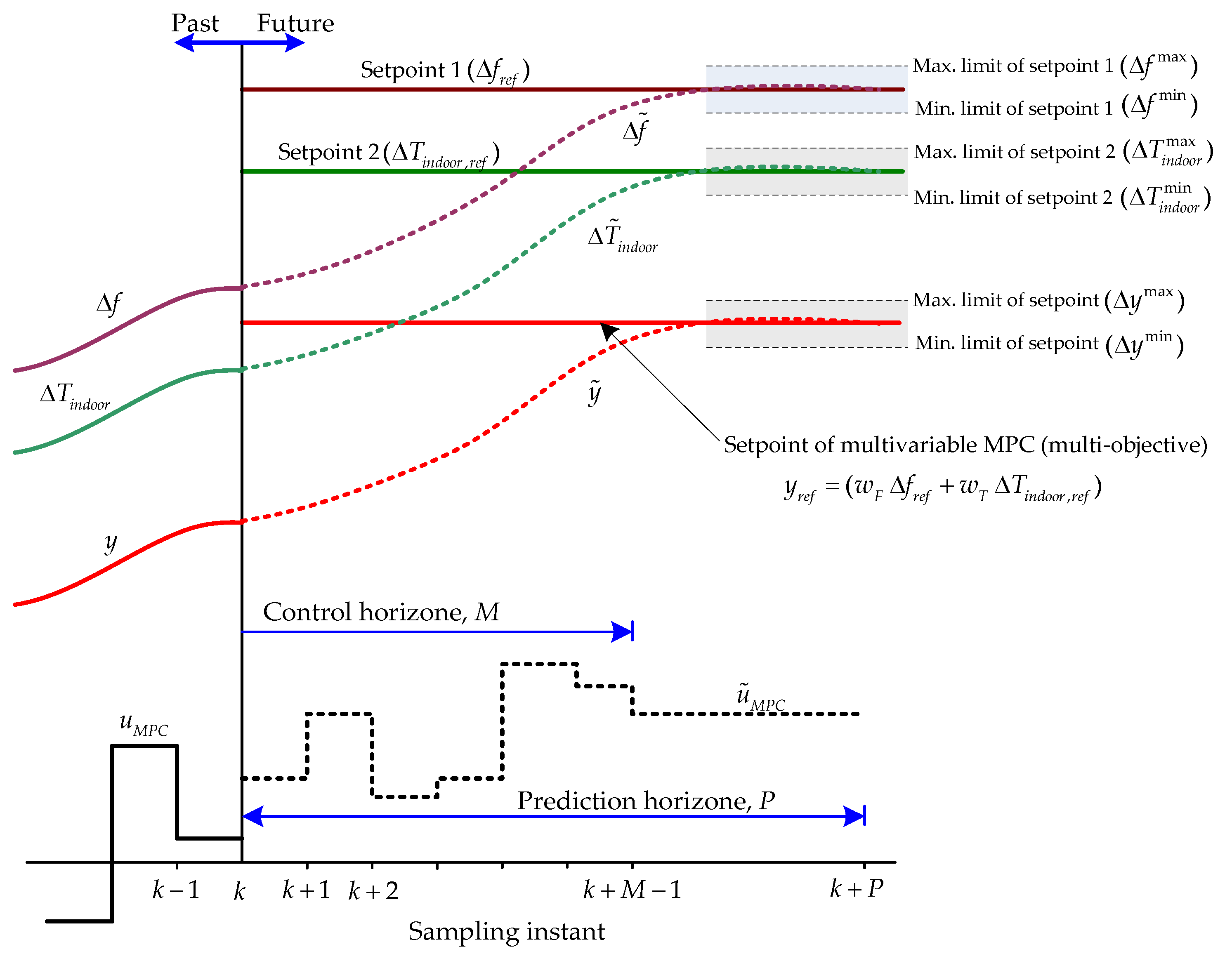
Typically, the MPC can apply for controlling multiple-input multiple-output (MIMO) and single-input single-output (SISO) systems [25,26,27,28,29]. However, the MPC may deteriorate for (reduce to) a single-input multiple-output (SIMO) system (i.e., single control signal with multi-objective controlling) because it is difficult to find the single optimal control signal to produce (satisfy) two objectives. Therefore, the multi-objective MPC has been proposed in this work, as shown in Figure 5. The multi-objective of MPC sums up the multiple setpoints to a single setpoint and the system is transferred to be the SISO system.
As shown in Figure 5, the multivariable MPC is applied for the power control of IAC groups in order to provide two objectives: (1) to stabilize the frequency deviation of microgrid ( Δ f ) , and (2) to maintain the indoor temperature of the IACs oscillating in the acceptable indoor temperature deviation range ( Δ T i n d o o r ) . The multivariable MPC for IACs control consists of setpoint one and setpoint two. Setpoint one is the reference frequency deviation ( Δ f r e f ) , which has the minimum–maximum deviation limits of Δ f min and Δ f max , respectively. Setpoint two is the reference of indoor temperature deviation ( Δ T i n d o o r ,   r e f ) which has the minimum–maximum deviation limits of Δ T i n d o o r min and Δ T i n d o o r max , respectively. The setpoint one and setpoint two are multiplied by weights w F and w T , respectively, before being summed up to be the setpoint of conventional MPC, i.e., y r e f = w F Δ f r e f + w T Δ T i n d o o r ,   r e f .
In addition, to control the temperature for the people’s comfort, the IACs are divided into n groups. Each IAC group has different ranges of acceptable indoor temperature limits. The DMPC is used to control the consumption power of the IAC group.
Figure 6 displays the details of setpoint one, setpoint two, and control signals of the IAC group. For setpoint one, the frequency deviation varies between the minimum and maximum limits. Setpoint one is set at the same desired minimum and maximum limits for all DMPCs. For setpoint two, the indoor temperature deviations are set based on the IAC owner preferences. Each IAC group has different desired minimum and maximum temperature deviation limits. For the control signal, each DMPC has its control signal, which is used to control the power consumption of the IAC group to produce the desired frequency deviation (Setpoint 1) and the indoor temperature deviation (Setpoint 2) set in advance.
Note that the system in Figure 6 is the MIMO system. However, for the problem of controlling one group of IACs, we consider the study system to be the SIMO system (Single input: the consumption power of IAC, multiple outputs: indoor temperature variation and system frequency deviation). When two outputs sum up to be one output, the SIMO system is transferred to the SISO system. This consideration is intended to explain one group of IACs.
The IAC groups are classified based on the preferred indoor temperature deviation ranges [ Δ T i n d o o r ,   n min       Δ T i n d o o r ,   n max ] . As shown in Figure 6, when setting the desired frequency deviation of the microgrid [ Δ f min       Δ f max ] for all DMPCs and selecting the different w T ,   n for each DMPCs can make [ Δ T i n d o o r ,   n min       Δ T i n d o o r ,   n max ] for each IAC group different.
In this work, the conventional MPC is applied for the IAC controller with the objective to control each group of IACs. Therefore, the structure of MPC in this work does not change. However, the control signal before summing up is a different signal. Then, the different MPCs are used for each IAC group and in this work, is called DMPC. Therefore, the state vector ( x n = [ Δ P I A C s ,   n     Δ f     Δ P D S     Δ P G o v     Δ P I n t     Δ P L o a d     Δ P W i n d     Δ P S o l a r ] T ) is different for the nth IAC group.
Consider the microgrid with IAC control in Figure 2 and the state space in (1) and (2), the multi-objective DMPC for the nth IAC group can be formulated as
x n ( k + 1 ) = A   x n ( k ) + B u u n ( k ) + B d d n ( k ) + B v v n ( k ) y n ( k ) = y ˜ n ( k ) + z n ( k ) = C x n ( k ) + D u u n ( k ) + D d d n ( k ) + D v v n ( k ) + z n ( k ) }
where x n = [ Δ P I A C s ,   n     Δ f     Δ P D S     Δ P G o v     Δ P I n t     Δ P L o a d     Δ P W i n d     Δ P S o l a r ] T . It can be assumed that all IAC groups have the same state space model plant, i.e., A ,   B u , B d , B v ,   C ,   D u ,   D d , and D v .
The DMPC solves the following optimization problem,
min u n ( k ) M j = 1 M [ y n ( k + j ) y r e f , n ( k + j ) ] T   W y [ y n ( k + j ) y r e f , n ( k + j ) ] + [ u n ( k ) u n ( k 1 ) ] T W u [ u n ( k ) u n ( k 1 ) ]
Subject to
y n ( k + 1 ) = y n ( k ) + A i = 0 n T δ i   u n ( k i )
Δ u n max + u n ( k 1 ) u n ( k ) Δ u n max + u n ( k 1 ) ,
where y n ( k + j ) = w F , n Δ f n ( k + j ) + w T , n Δ T i n d o o r ,   n ( k + j ) is the output of the system which is the summation of frequency deviation and temperature deviation multiplied by the weights. y r e f , n ( k + j ) = w F , n Δ f r e f , n ( k + j ) + w T , n Δ T i n d o o r ,   r e f , n ( k + j ) is the desired profile, δ i , n is the step response coefficient of the nth DMPC for controlling the nth IACs group.
In addition, weights of the nth IACs group, i.e., w F , n and w T ,   n , are optimized in Section 3.4 to minimize Δ f and produce the desired Δ T i n d o o r ,   n with the acceptable deviation ranges, such as [ Δ T i n d o o r ,   n min       Δ T i n d o o r ,   n max ] .

3.4. Weight Tuning of Multi-Objective DMPC

To produce the effective multi-objective DMPC control, tuning weights ( w F , n and w T ,   n ) of the two setpoints ( Δ f and Δ T i n d o o r ,   n ) is a necessary procedure. Selecting appropriate weights of each objective can produce different minimum and maximum ranges of the setpoints ( [ Δ f min       Δ f max ] and [ Δ T i n d o o r ,     n min           Δ T i n d o o r ,     n max   ] ). The objective with significant weight is more important than the objective with a smaller weight. The significant weight can produce a flat minimum–maximum range of the setpoint, while a small weight can produce a wide minimum–maximum range. Moreover, each setpoint has a different minimum–maximum range, i.e., the frequency deviation has the minimum–maximum range of ± 0.5     Hz . In contrast, the indoor temperature deviation has the minimum–maximum ranges of ±0.5 °C to ±0.3 °C. In addition, controlling the indoor temperature deviation is more accessible than controlling the microgrid frequency deviation. Therefore, the weighting of frequency deviation is more significant than the weighting of indoor temperature deviation. For simplicity, in this work, the frequency deviation weights of each DMPC are set to the same, i.e., w F , n = w F , and the indoor temperature weights are adjusted to maintain the indoor temperature in the acceptable ranges.
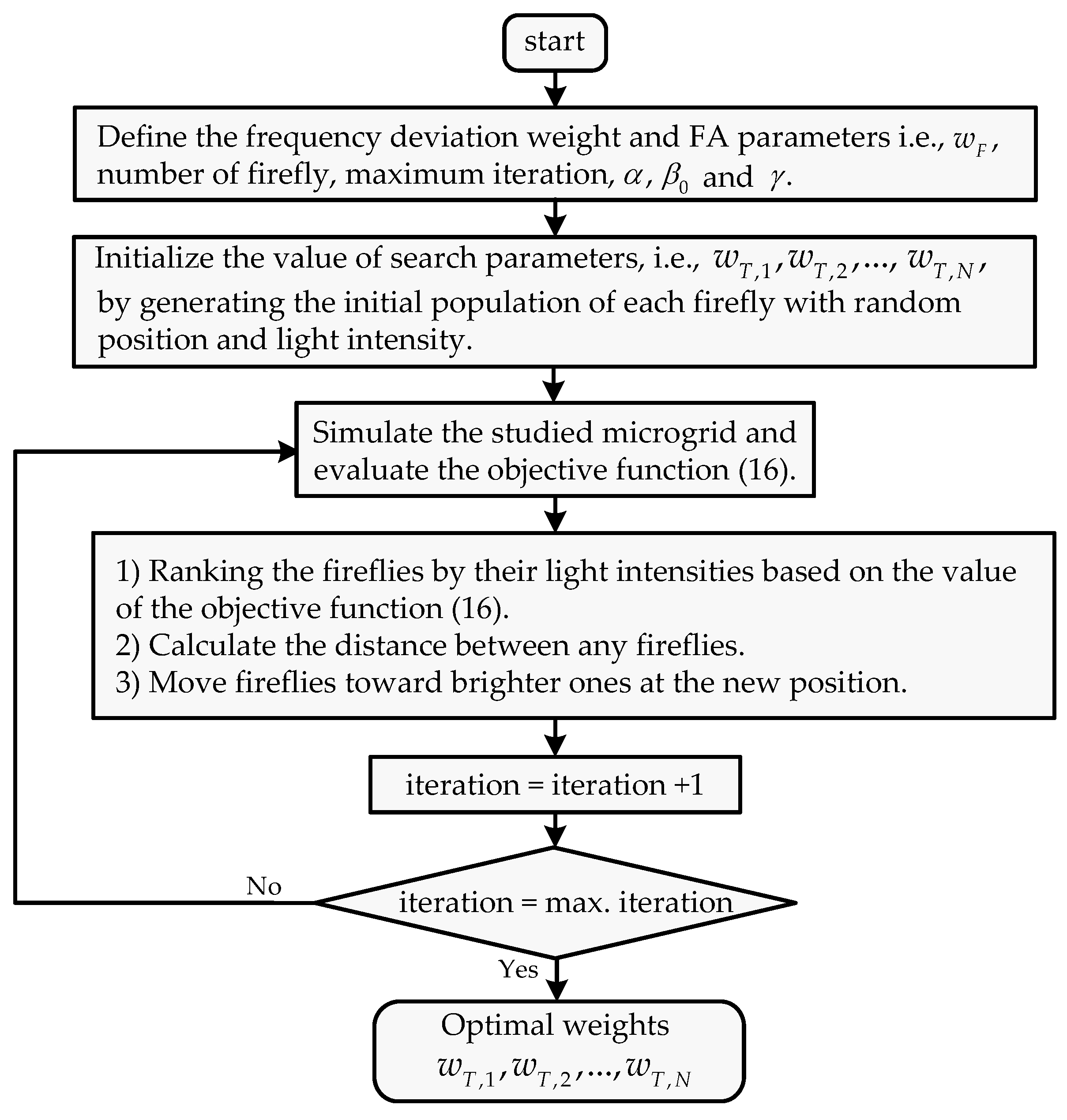
The indoor temperature deviation weights of the N groups of IACs ( w T , 1 ,     w T , 2 ,   ,   w T , N ) are optimized by the firefly algorithm (FA) [39]. The objective of the optimization is to minimize the integral absolute frequency deviation and maintain the indoor temperature deviation varied among the acceptable limits. The optimization problem can be formulated by
Minimize     J 1 =     t i n i t t f i n a l | Δ f ( t )   | d t
Subject to
Δ T i n d o o r ,   n min Δ T i n d o o r ,   n ( t ) Δ T i n d o o r ,   n max ,
w T ,   n min w T ,   n ( t ) w T ,   n max ,                 n = 1 , , N
where t is the time instant, t i n i t and t f i n a l are the initial and the final simulation times, respectively. The procedure of the FA-based temperature weight tuning is shown in Figure 7. Note that α is the randomization parameter, β 0 is the attractiveness at iteration 0, and γ is the light absorption coefficient of the FA [37].

4. Simulation Results

The simulation results are conducted by the MATLAB/Simulink program. In the simulation studies, it is supposed that the studied microgrid in Figure 1, with parameters in Table 1, is performed under the random load, PV power, wind power, outdoor temperature, and number of IACs, of the three case studies, as shown in Figure 8. In this work, the DMPCs have been used to control the IAC groups in order to stabilize the frequency of MG and maintain the indoor temperature in acceptable ranges.
As shown in Figure 8, in case 1, the PV power is perfect, the wind power is smooth, the load and the number of IACs are high, and the outdoor temperature is low. This case assumes that the frequency fluctuates little in a typical case. In case 2, the PV power significantly fluctuates, the wind power fluctuates, but with a lower magnitude around mid-day (10.00–16.00 h), the load and the number of IACs are low, and the outdoor temperature is high. In case 3, the PV and wind power significantly fluctuate; the load, the number of IACs, and the outdoor temperature are high. The variation in the number of IACs shown in Figure 8 implies that the total consumption power of IAC participation in PFR varies among daytime hours. Therefore, the MPC controller should successfully handle the variation in the IAC number.
Furthermore, the parameters of the thermal and electrical model of IACs are provided as follows [20]: the heat capacity C a = 1.005     kJ / kg / ° C , the density of the air ρ a = 1.205     kJ / m 3 , the room’s volume V R = 250   m 3 , the surface area of the room S R = 100   m 2 , the ambient temperatures T A set as in Figure 8d, the heat transfer coefficient UO,A = 3.6 W/m3/°C, and the air exchange times between the room and the ambiance ξ = 0.5   h 1 .
In addition, the IACs are assumed to be classified into six groups. For simple simulation, the number of IACs in each group are the same, i.e., the number of IACs in Figure 8e are divided by 6. For each IAC group, the minimum and maximum ranges of indoor temperature deviations are set as ±0.5 °C, ±1.0 °C, ±1.5 °C, ±2.0 °C, ±2.5 °C, and ±3.0 °C, as shown in Table 2. The IAC owner selects these indoor temperature deviation ranges. For example, if the IAC owner selects the indoor temperature deviation range ±0.5 °C and sets the indoor temperature as 25 °C, when the IAC is turned on, the indoor temperature varies between 24.5 °C and 25.5 °C. The frequency deviations of all DMPCs are set as ± 0.5   Hz , which is consistent with the allowance frequency of the studied microgrid.
In the design of DMPCs, some parameters are selected based on [12], and the others are set based on trial and error to produce frequency deviation and temperature deviation as defined. The parameters of DMPC controllers are set as follows: P = 10 ,   M = 3 , sampling time interval = 0.1 s, W y = 1 ,   W u = 0.1 , range of control signal u = [ 0       1 ] , range of output y = [ 0.01       0.01 ] , reference frequency deviation Δ f r e f = 0 , and the reference indoor temperature deviation Δ T i n d o o r , r e f = 0 . Note that all six IAC groups use the same DMPCs parameters.
In the optimization of weights of multi-objective DMPC, the frequency deviation weight is set to 50 (i.e., w F = 50 ), and the indoor temperature deviations weights are optimized by FA, as displayed in Figure 7. The parameters of FA and search parameters are provided as follows: the number of fireflies = 20, maximum iteration = 100, α = 0.5 , β 0 = 0.1 , γ = 1 , and [ w T ,   n min           w T ,   n max ] = [ 0.001           1 ] . [ Δ T i n d o o r ,   n min       Δ T i n d o o r ,   n max ] are provided in Table 2.
Moreover, the weights of indoor temperature are optimized based on the time of day, 00.01–07.00 h, 07.01–18.00 h, and 18.01–24.00 h. Between 07.01–18.00 h, two temperature weights are used based on the PV power generation pattern, i.e., perfect PV (case 1) and non-perfect PV (cases 2 and 3). As a result, the convergence curve of the objective function of FA is shown in Figure 9. Table 2 shows the weight of indoor temperature deviations. The weights of non-perfect PV are higher than the weights of perfect PV due to the high fluctuation of frequency caused by the non-perfect PV.
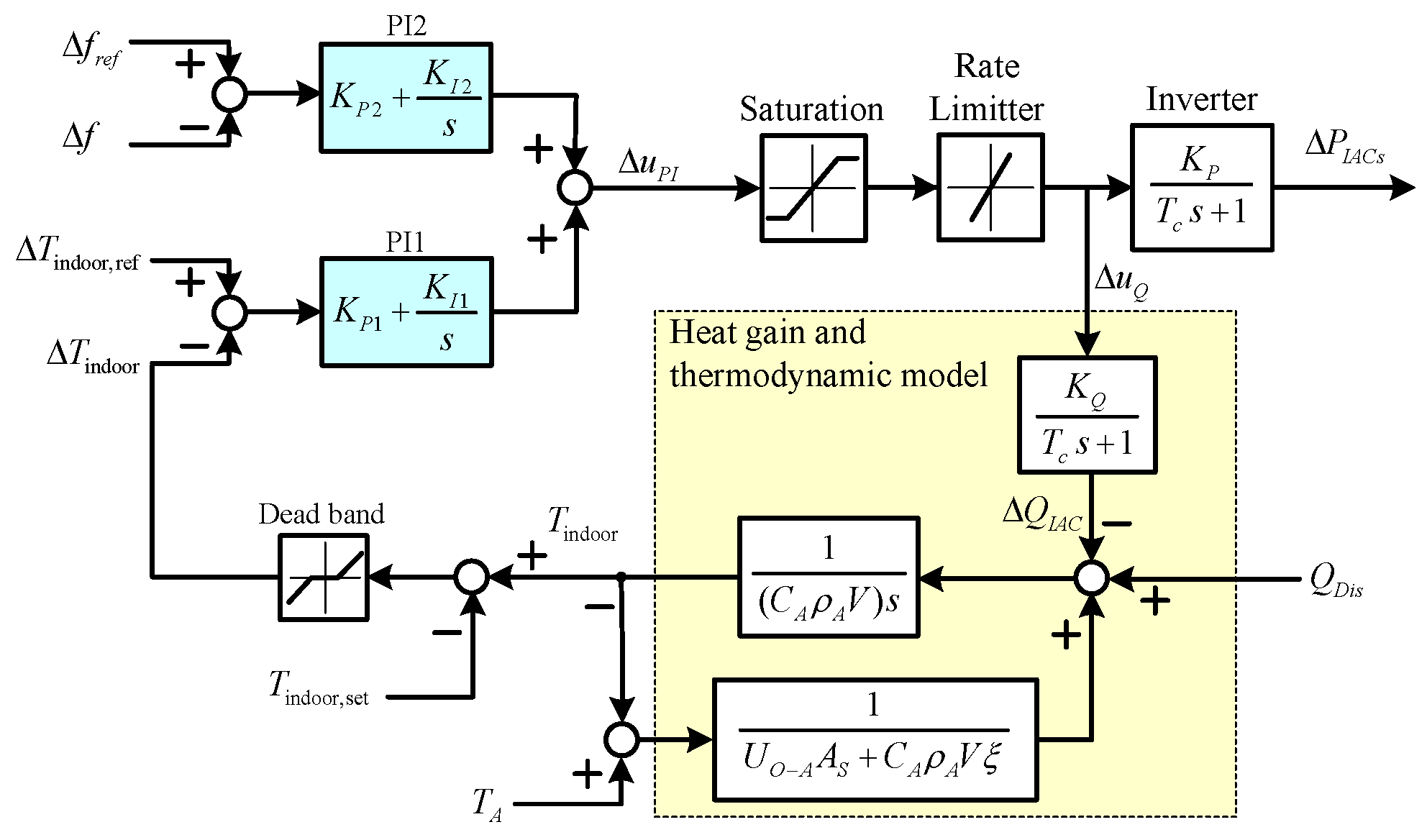
To evaluate the effectiveness of the proposed multi-objective DMPC performance, the DMPC is compared to “PI” and “No PFR” controllers. The “PI” is the centralized proportional integral (PI), which is used to control the power consumption of the IACs for PFR. Figure 10 shows the PI controllers for IAC control. The PI1 is used to control the indoor temperature, while the PI2 is used to control the microgrid frequency deviation. The PI parameters are optimized by FA, the same as the DMPC, to produce the minimum of integral absolute frequency deviation and maintain the indoor temperature deviation, the same as the average temperature of the DMPC, i.e., ± ( 0.5 + 1.0 + 1.5 + 2.0 + 2.5 + 3.0 ) / 6 = ± 1.75   ° C. The problem of PI parameter optimization can be formulated by
Minimize     J 2 =     t i n i t t f i n a l | Δ f ( t )   | d t
Subject to
Δ T i n d o o r min Δ T i n d o o r ( t ) Δ T i n d o o r max
where Δ T i n d o o r min = 1.75 °C and Δ T i n d o o r max = 1.75 °C are the minimum and maximum of indoor temperature deviation. Consequently, the optimal PI parameters obtained from the FA optimization are K P 1 = 3.251 , K I 1 = 0.037 , K P 2 = 4.982 , and K I 2 = 0.473 .
Moreover, the “No PFR” is the IAC that acts as a conventional load and does not participate in PFR. Referred to in Figure 10, only the PI1 is used to control the indoor temperature. Therefore, the PI1 parameters are set as K P 1 = 0.527 and K I 1 = 0.032 to produce minimum temperature deviation.
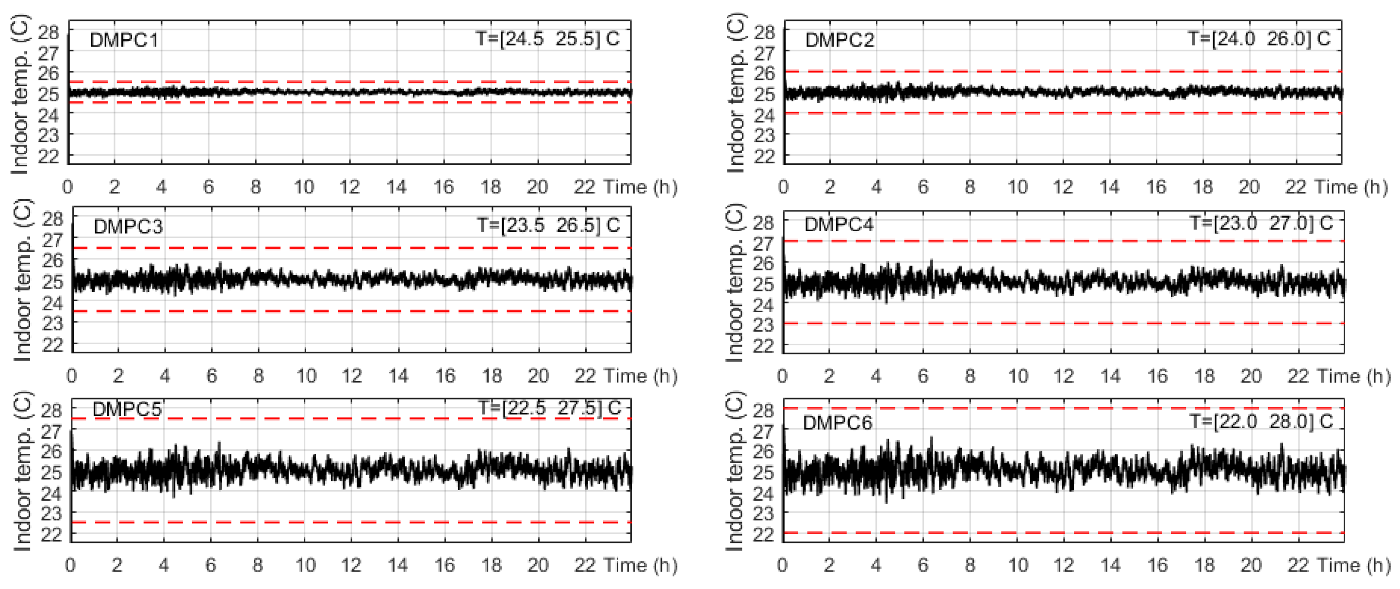
Figure 11 displays the indoor temperature deviation by DMPCs of case 1. The setting temperature is 25 °C. For DMPC 1, the user minimum–maximum temperature deviation preferences are ±0.5 °C. Therefore, the indoor temperature of DMPC 1 varies between 24.5 °C and 25.5 °C. Similarly, for DMPC 2–6, due to the user preference temperature, deviations are ±1 °C, ±1.5 °C, ±2 °C, ±2.5 °C, and ±3 °C, and the indoor temperatures of DMPCs 2–6 vary between [24 °C–26 °C], [23.5 °C–26.5 °C], [23 °C–27 °C], [22.5 °C–27.5 °C], and [22 °C–28 °C], respectively. The DMPCs can successfully regulate the indoor temperature for each IAC group, as defined in advance.
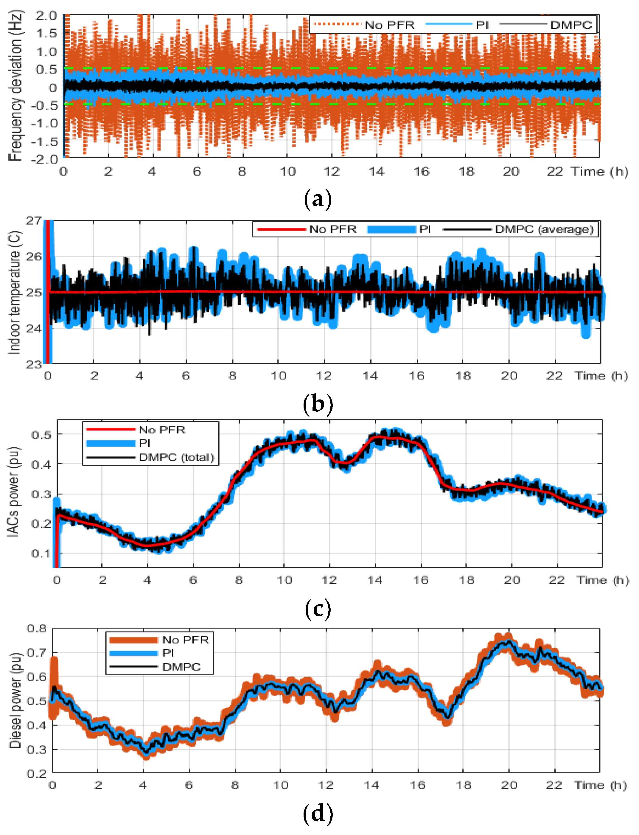
Figure 12 exhibits the frequency deviation, indoor temperature, IAC power consumption, and diesel power of case 1. As shown in Figure 12a, the frequency deviation of No PFR is higher than the frequency limit of ± 0.5 Hz, while the frequency deviations of PI and DMPC are lower than the frequency limit. This wider frequency band for steady-state operation ( ± 0.5 Hz) may be applied without adversely impacting the quality of supply expected by the connected customers and improving the economic efficiency of the associated investment [4,5].
Figure 12b shows the indoor temperature of No PFR, PI, and DMPC. The case of No PFR can keep the indoor temperature at the setting temperature (25 °C), while the PI and DMPC can successfully regulate the indoor temperature near the setting temperature with acceptable variation ranges (±1.75 °C).
Figure 12c displays the IACs consumption power of No PFR, PI, and DMPC. The IACs consumption power in the case of No PFR is very smooth, while the IACs consumption power of PI and DMPC oscillates across the smooth line of the No PFR. The variation in IAC power consumption of PI and DMPC is used for regulating system frequency. Figure 12d displays the diesel power of No PFR, PI, and DMPC. The diesel power of No PFR oscillates more than that of PI and DMPC.
Figure 13 and Figure 14 depict the simulation results of case 2. In this case, PV generation fluctuates between 7.00–18.00 h. Therefore, the frequency deviation significantly fluctuates between 7.00–18.00 h. However, the frequency reduction in the case of the DMPCs is higher than that of the PI controller.
Figure 15 and Figure 16 show the simulation results of case 3. In this case, the indoor temperature setting is changed during simulation time, i.e., 22 °C, 23 °C and 24 °C, respectively. The DMPC can maintain frequency deviation in the acceptable range as well as produce temperature as the user-defined, successfully. In addition, the DMPC can produce a smaller frequency deviation than the PI controller.
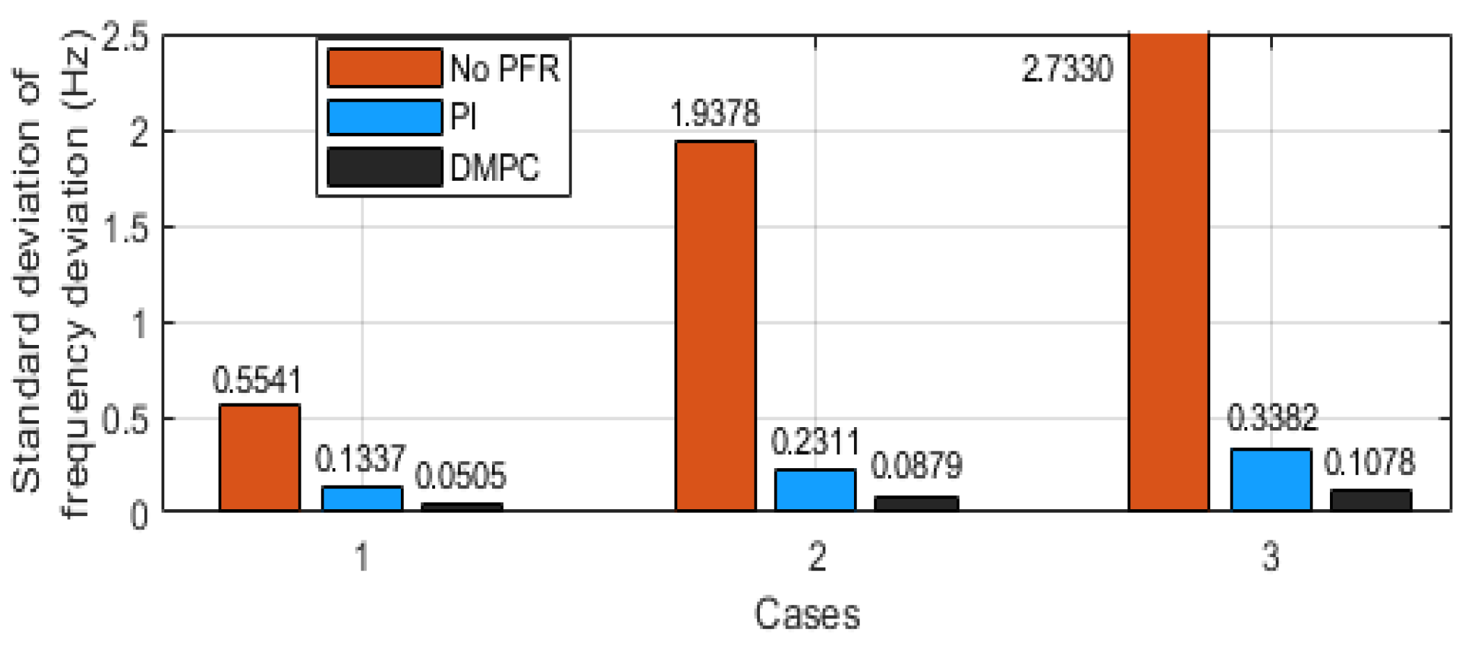
Figure 17 displays the standard deviation (STD) of the frequency deviation of cases 1–3. For case 1, the STD of frequency deviation of No PFR is 0.5541. This means that most of the frequency spread (around 80%) from the reference frequency is ± 0.5541   Hz . Similarly, the frequency spreads from the reference’s frequency of the PI and the DMPC are ± 0.1337   Hz and ± 0.0505     Hz , respectively. For case 2, the frequency spreads from the reference’s frequency of No PFR, PI, and DMPC are ± 1.9378   Hz , ± 0.2311   Hz , and ± 0.0879     Hz , respectively. For case 3, the frequency spreads from the reference’s frequency of No PFR, PI, and DMPC are ± 2.7330   Hz , ± 0.3382   Hz , and ± 0.1078   Hz , respectively. As shown in the three cases, the DMPC has the lowest STD, which indicates that the frequency in the case of DMPC is more adjacent to the reference frequency than that of No PFR and PI.
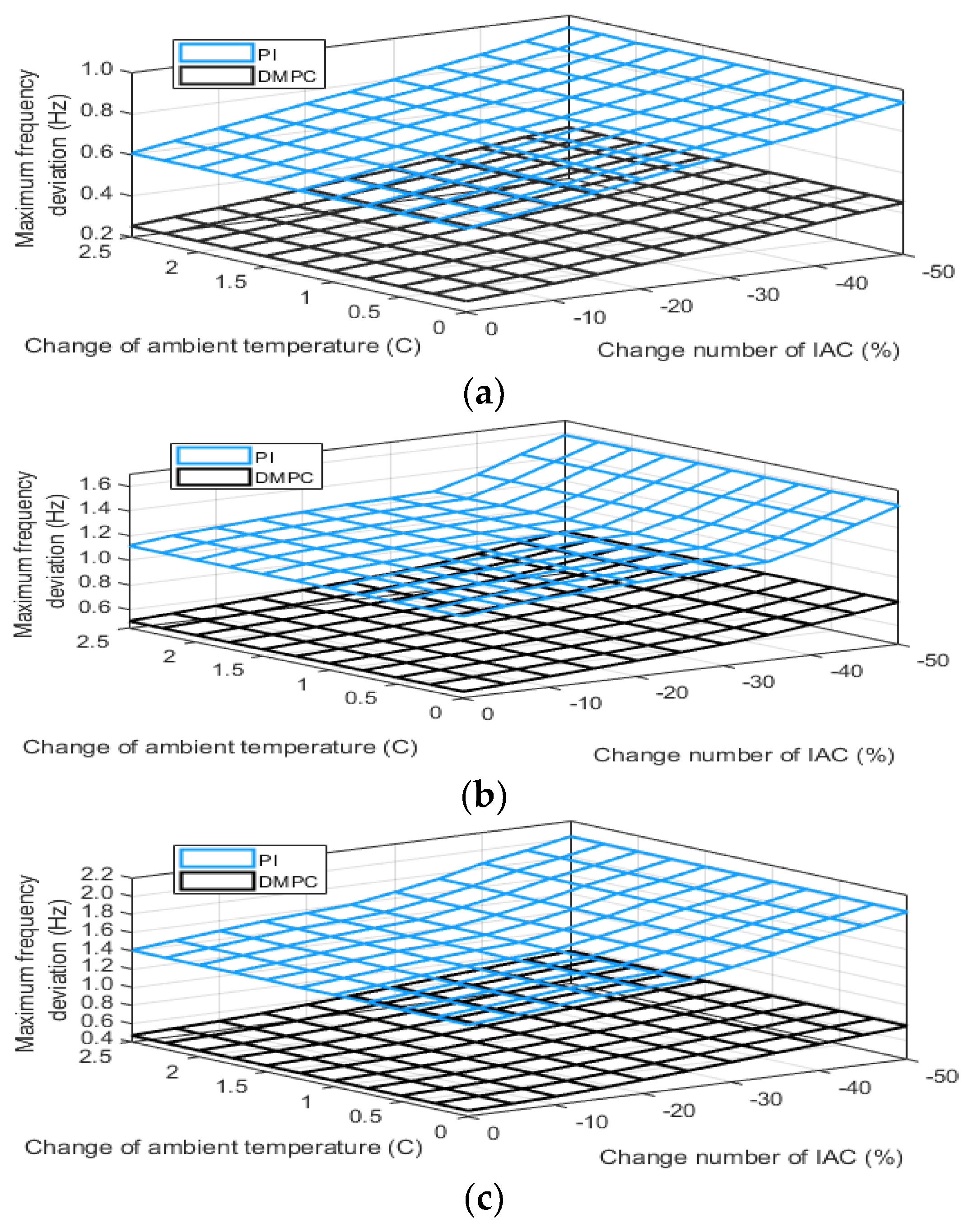
To confirm the robustness of the control method against the changing number of IACs from nominal number to −50%, and the change in ambient temperature from 0 °C to 2.5 °C, as shown in Figure 18, it can be observed that the change in ambient temperature does not change the variation of maximum frequency deviation. In contrast, the decreasing number of IAC causes the variation of maximum frequency deviation. However, the variation of maximum frequency deviation in the case of DMPC is lower than that of PI. These results imply that the DMPC is superior to PI in terms of the number of IAC variations.
The simulation results of the three case studies confirm that the DMPC is superior to No PFR and PI. The system’s frequency, which is controlled by the DMPC, oscillates in terms of the acceptable limits, while some parts of the frequencies in the cases of No PFR and PI oscillate out of the frequency limits. Moreover, the DMPC can change the indoor temperature according to the user’s preference and is robust to temperature and number of IACs variations over the PI controller.

5. Conclusions

In this paper, we propose a multi-objective decentralized model predictive control (DMPC)-based inverter air conditioner (IAC) power consumption control for stabilizing frequency deviation and maintaining varied indoor temperature in a preferred range. The study can be concluded as follows:
(1)
The controlling of IAC power consumption is used to suppress the frequency deviation of microgrid with high penetration of wind and PV generators.
(2)
The multi-objective DMPC is used to control the power consumption of the six IAC groups classified by acceptable variation of the indoor temperature range.
(3)
In the multi-objective DMPC design procedure, the weights of temperature deviation of the six IACs groups are optimized using the firefly algorithm (FA) to minimize the integral absolute frequency deviation and maintain the indoor temperature inside the acceptable ranges.
(4)
Simulation results on the studied microgrid demonstrate that the DMPC is able to suppress the frequency variation and control the temperature deviation concurrently when the temperature setting is constant and adjusted.
(5)
The DMPC is able to reduce frequency deviation, satisfying indoor temperature preferences, and is robust to the various number of IACs, over the proportional-integral PI controller.
In addition, in future work, the IACs will be used for virtual inertia emulator control of the microgrid with high penetration renewable energy resources.

Author Contributions

Conceptualization, J.P. and I.N.; methodology, J.P.; software, J.P.; validation, J.P.; formal analysis, J.P.; investigation, J.P.; resources, J.P.; data curation, J.P.; writing—original draft preparation, J.P.; writing—review and editing, J.P., P.P. and I.N.; visualization, J.P.; supervision, J.P. and I.N.; project administration, J.P.; funding acquisition, J.P., P.P. and I.N. All authors have read and agreed to the published version of the manuscript.

Funding

This work was supported by the National Research Council of Thailand.

Conflicts of Interest

The authors declare no conflict of interest.

Nomenclature

ACAir conditioner
BESSBattery energy storage system
DGDistributed generation
DMPCDecentralized model predictive control
FAFirefly algorithm
IACInverter air conditioner
MGMicrogrid
MPCModel predictive control
PFRPrimary frequency regulation
PHEVPlug-in hybrid electric vehicle
PIProportional integral
PMSGPermanent magnet synchronous generator
PVPhotovoltaic
RES Renewable energy sources
RoCoFRate of change of frequency
SGSynchronous generator
VSGVirtual synchronous generator

References

  1. Han, Y.; Li, H.; Shen, P.; Coelho, E.A.A.; Guerrero, J.M. Review of active and reactive power sharing strategies in hierarchical controlled microgrids. IEEE Trans. Power Electron. 2017, 32, 2427–2451. [Google Scholar] [CrossRef] [Green Version]
  2. Bose, U.; Chattopadhyay, S.K.; Chakraborty, C.; Pal, B. A novel method of frequency regulation in microgrid. IEEE Trans. Ind. Appl. 2019, 55, 111–121. [Google Scholar] [CrossRef]
  3. Hajimiragha, A.H.; Zadeh, M.R.D.; Moazeni, S. Microgrids Frequency Control Considerations Within the Framework of the Optimal Generation Scheduling Problem. IEEE Trans. Smart Grid 2014, 6, 534–547. [Google Scholar] [CrossRef]
  4. Technical Advice on Performance Standards for Stand-Alone Power Systems. Australian Energy Market Commission, 14 April 2020, Project Number: 12526485. Available online: https://www.aemc.gov.au/sites/default/files/2020-05/GHD%20Report%20-%20AEMC%20Performance%20standards%20for%20SAPS%202020.04.14.pdf (accessed on 16 October 2021).
  5. IEEE 1547.4-2011—IEEE Guide for Design, Operation, and Integration of Distributed Resource Island Systems with Electric Power Systems. IEEE Standards Coordinating Committee 21, USA. 20 July 2011. Available online: https://ieeexplore.ieee.org/servlet/opac?punumber=5960749 (accessed on 16 October 2021).
  6. Lasseter, R.H.; Paigi, P. Microgrid: A conceptual solution. In Proceedings of the 2004 IEEE 35th Annual Power Electronics Specialists Conf. (IEEE Cat. No.04CH37551), Aachen, Germany, 20–25 June 2004; Volume 6, pp. 4285–4290. [Google Scholar]
  7. Ahmethodzic, L.; Music, M. Comprehensive review of trends in microgrid control. Renew. Energy Focus 2021, 38, 84–96. [Google Scholar] [CrossRef]
  8. Sitompul, S.; Fujita, G. Impact of Advanced Load-Frequency Control on Optimal Size of Battery Energy Storage in Islanded Microgrid System. Energies 2021, 14, 2213. [Google Scholar] [CrossRef]
  9. Mazzeo, D.; Matera, N.; De Luca, P.; Baglivo, C.; Congedo, P.M.; Oliveti, G. A literature review and statistical analysis of photovoltaic-wind hybrid renewable system research by considering the most relevant 550 articles: An upgradable matrix literature database. J. Clean. Prod. 2021, 295, 126070. [Google Scholar] [CrossRef]
  10. Fang, J.; Li, H.; Tang, Y.; Blaabjerg, F. On the Inertia of Future More-Electronics Power Systems. IEEE J. Emerg. Sel. Top. Power Electron. 2019, 7, 2130–2146. [Google Scholar] [CrossRef]
  11. Othman, M.H.; Mokhlis, H.; Mubin, M.; Talpur, S.; Aziz, N.F.A.; Dradi, M.; Mohamad, H. Progress in control and coordination of energy storage system-based VSG: A review. IET Renew. Power Gener. 2020, 14, 177–187. [Google Scholar] [CrossRef]
  12. Pahasa, J.; Ngamroo, I. Coordinated PHEV, PV, and ESS for Microgrid Frequency Regulation Using Centralized Model Predictive Control Considering Variation of PHEV Number. IEEE Access 2018, 6, 69151–69161. [Google Scholar] [CrossRef]
  13. Zhang, W.; Lian, J.; Chang, C.; Kalsi, K. Aggregated modeling and control of air conditioning loads for demand response. IEEE Trans. Power Syst. 2013, 28, 4655–4664. [Google Scholar] [CrossRef]
  14. Palensky, P.; Dietrich, D. Demand Side Management: Demand Response, Intelligent Energy Systems, and Smart Loads. IEEE Trans. Ind. Inform. 2011, 7, 381–388. [Google Scholar] [CrossRef] [Green Version]
  15. Song, M.; Gao, C.; Yan, H.; Yang, J. Thermal Battery Modeling of Inverter Air Conditioning for Demand Response. IEEE Trans. Smart Grid 2018, 9, 5522–5534. [Google Scholar] [CrossRef]
  16. Hui, H.; Ding, Y.; Liu, W.; Lin, Y.; Song, Y. Operating reserve evaluation of aggregated air conditioners. Appl. Energy 2017, 196, 218–228. [Google Scholar] [CrossRef]
  17. Mahdavi, N.; Braslavsky, J.H.; Seron, M.M.; West, S. Model Predictive Control of Distributed Air-Conditioning Loads to Compensate Fluctuations in Solar Power. IEEE Trans. Smart Grid 2017, 8, 3055–3065. [Google Scholar] [CrossRef]
  18. Shi, Q.; Li, F.; Liu, G.; Shi, D.; Yi, Z.; Wang, Z. Thermostatic load control for system frequency regulation considering daily demand profile and progressive recovery. IEEE Trans. Smart Grid 2019, 10, 6259–6270. [Google Scholar] [CrossRef]
  19. Mendieta, W.; Canizares, C.A. Primary Frequency Control in Isolated Microgrids Using Thermostatically Controllable Loads. IEEE Trans. Smart Grid 2021, 12, 93–105. [Google Scholar] [CrossRef]
  20. Hui, H.; Ding, Y.; Lin, Z.; Siano, P.; Song, Y. Capacity allocation and optimal control of inverter air conditioners considering area control error in multi-area power systems. IEEE Trans. Power Syst. 2020, 35, 332–345. [Google Scholar] [CrossRef]
  21. Jiang, T.; Ju, P.; Wang, C.; Li, H.; Liu, J. Coordinated control of air-conditioning loads for system frequency regulation. IEEE Trans. Smart Grid 2021, 12, 548–560. [Google Scholar] [CrossRef]
  22. Xiao, Y.; Su, Q.; Bresler, F.S.S.; Carroll, R.; Schmitt, J.R.; Olaleye, M. Performance-based regulation model in PJM wholesale markets. In Proceedings of the 2014 IEEE PES General Meeting|Conference & Exposition, National Harbor, MD, USA, 27–31 July 2014; pp. 1–5. [Google Scholar]
  23. Blum, D.H.; Zakula, T.; Norford, L.K. Opportunity cost quantification for ancillary services provided by heating, ventilating, and air-conditioning systems. IEEE Trans. Smart Grid 2017, 8, 1264–1273. [Google Scholar] [CrossRef]
  24. Li, W.; Du, P.; Lu, N. Design of a New Primary Frequency Control Market for Hosting Frequency Response Reserve Offers From Both Generators and Loads. IEEE Trans. Smart Grid 2017, 9, 4883–4892. [Google Scholar] [CrossRef]
  25. Maciejowski, J.M. Predictive Control with Constraints; Prentice-Hall: Upper Saddle River, NJ, USA, 2001. [Google Scholar]
  26. Rossiter, J.A. Model-based Predictive Control: A Practical Approach; CRC Press: Boca Raton, FL, USA, 2003. [Google Scholar]
  27. Seborg, D.E.; Edgar, T.F.; Mellichamp, D.A. Process Dynamics and Control, 2nd ed.; John Wiley & Sons, Inc.: Hoboken, NJ, USA, 2003. [Google Scholar]
  28. Rawlings, J.B.; Mayne, D.Q. Model Predictive Control: Theory and Design; Nob Hill Publishing: Madison, WI, USA, 2009. [Google Scholar]
  29. Bemporad, A.; Ricker, N.L.; Morari, M. Model Predictive Control Toolbox™ User’s Guide; MATH WORKS Inc.: Natick, MA, USA, 2019. [Google Scholar]
  30. Zheng, Y.; Li, S.; Tan, R. Distributed Model Predictive Control for On-Connected Microgrid Power Management. IEEE Trans. Control. Syst. Technol. 2018, 26, 1028–1039. [Google Scholar] [CrossRef]
  31. Moradzadeh, M.; Boel, R.; Vandevelde, L. Voltage coordination in multi-area power systems via distributed model predictive control. IEEE Trans. Pow. Syst. 2013, 28, 513–521. [Google Scholar] [CrossRef] [Green Version]
  32. Ma, M.; Zhang, C.; Liu, X.; Chen, H. Distributed Model Predictive Load Frequency Control of the Multi-Area Power System after Deregulation. IEEE Trans. Ind. Electron. 2016, 64, 5129–5139. [Google Scholar] [CrossRef]
  33. Qin, S.; Chang, Y.; Xie, Z.; Li, S. Improved virtual inertia of PMSG-based wind turbines based on multi-objective model-predictive control. Energies 2021, 14, 3612. [Google Scholar] [CrossRef]
  34. Rafiee, A.; Batmani, Y.; Ahmadi, F.; Bevrani, H. Robust load-frequency control in islanded microgrids: Virtual synchronous generator concept and quantitative feedback theory. IEEE Trans. Power Syst. 2021, 36. [Google Scholar] [CrossRef]
  35. Kerdphol, T.; Rahman, F.S.; Watanabe, M.; Mitani, Y. Robust Virtual Inertia Control of a Low Inertia Microgrid Considering Frequency Measurement Effects. IEEE Access 2019, 7, 57550–57560. [Google Scholar] [CrossRef]
  36. Rakhshani, E.; Rodriguez, P. Inertia emulation in AC/DC interconnected power systems using derivative technique considering frequency measurement effects. IEEE Trans. Power Syst. 2017, 32, 3338–3351. [Google Scholar] [CrossRef]
  37. HHui, H.; Ding, Y.; Zheng, M. Equivalent Modeling of Inverter Air Conditioners for Providing Frequency Regulation Service. IEEE Trans. Ind. Electron. 2019, 66, 1413–1423. [Google Scholar] [CrossRef]
  38. Hui, H.; Ding, Y.; Chen, T.; Rahman, S.; Song, Y. Dynamic and Stability Analysis of the Power System with the Control Loop of Inverter Air Conditioners. IEEE Trans. Ind. Electron. 2021, 68, 2725–2736. [Google Scholar] [CrossRef]
  39. Yang, X.S. Engineering Optimisation: An Introduction with Metaheuristic Applications; Wiley: Hoboken, NJ, USA, 2010. [Google Scholar]
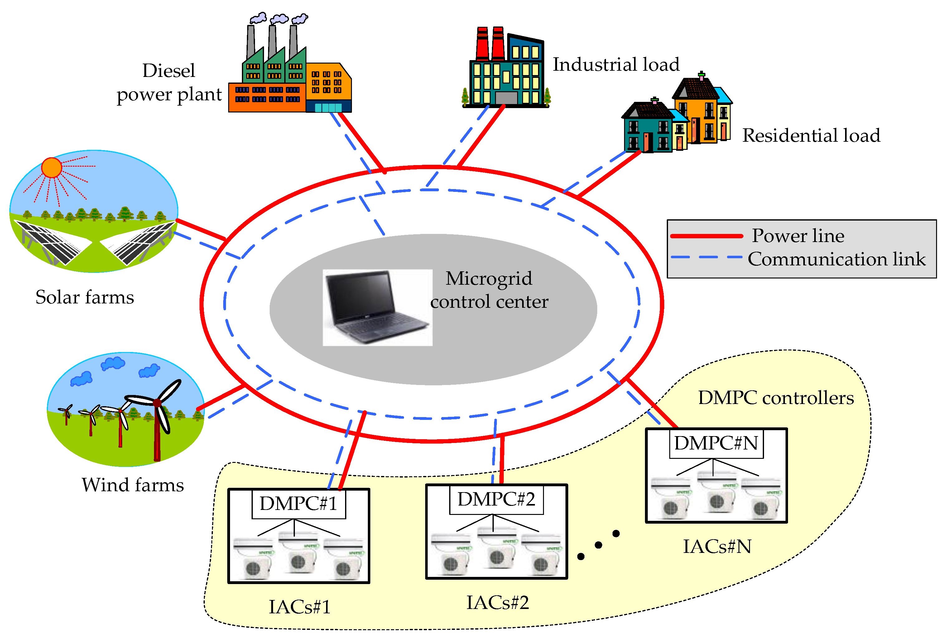
Figure 1. Microgrid with DMPC for IACs control.
Energies 14 06969 g001
Figure 2. Linearized model of the study microgrid with DMPC.
Energies 14 06969 g002
Figure 3. The multivariable DMPC for IACs control.
Energies 14 06969 g003
Figure 4. IACs power control and indoor temperature against frequency deviation.
Energies 14 06969 g004
Figure 5. Multivariable MPC for IACs control.
Energies 14 06969 g005
Figure 6. Details of setpoints and control signal of DMPCs for IACs control.
Energies 14 06969 g006
Figure 7. The procedure of FA-based temperature weight tuning.
Energies 14 06969 g007
Figure 8. Case studies: (a) PV power deviation, (b) wind power deviation, (c) random load deviation, (d) outdoor temperature, and (e) number of IAC.
Energies 14 06969 g008
Figure 9. Convergence curve of FA for the indoor temperature weight tuning.
Energies 14 06969 g009
Figure 10. PI controllers for IACs control.
Energies 14 06969 g010
Figure 11. Indoor temperature deviation of the DMPCs for IAC control of case 1 (the blue line is the indoor temperature, and the red dash lines are the minimum and maximum limits of the indoor temperature).
Energies 14 06969 g011
Figure 12. Simulation results of case 1 (a) frequency deviation (green dash lines are the frequency minimum and maximum limits), (b) indoor temperature, (c) IACs power consumption, and (d) diesel power.
Energies 14 06969 g012
Figure 13. Indoor temperature deviation of the DMPCs for IAC control of case 2.
Energies 14 06969 g013
Figure 14. Simulation results of case 2 (a) frequency deviation, (b) indoor temperature, (c) IACs power, and (d) diesel power.
Energies 14 06969 g014
Figure 15. Indoor temperature deviation of the DMPCs for IACs control of case 3.
Energies 14 06969 g015
Figure 16. Simulation results of case 3 (a) frequency deviation, (b) indoor temperature, (c) IACs consumption power, and (d) diesel power.
Energies 14 06969 g016
Figure 17. Standard deviation of frequency deviation.
Energies 14 06969 g017
Figure 18. Absolute maximum frequency deviation when system parameters change: (a) case 1, (b) case 2, and (c) case 3.
Energies 14 06969 g018
Table 1. System Parameters.
ParametersValue
Reference frequency, f r e f (Hz)50
Inertia constant, H (s)0.1
Damping characteristic of load, D (pu)0.12
Governor time constant, T g (s)0.1
Turbine time constant, T t (s)0.4
Primary droop factor, R (Hz/pu.MW)0.4
Secondary frequency controller, K i (s)0.1
Total number of IAC (units)2000
Capacity of IAC (kW)8
Time constant of the compressor of the IACs, T c (s)0.02
Compressor of the IACs gain, K P 40
Feedback heat gain of the IACs, K Q 120
Table 2. Weighs of indoor temperature deviations for DMPCs.
[ Δ T i n d o o r ,   n min       Δ T i n d o o r ,   n max ]
(°C)
w T
00.01–07.00 h07.01–18.00 h
(Perfect PV/Non-Perfect PV)
18.01–24.00 h
DMPC 1[−0.5 0.5]0.4860.504/0.8190.347
DMPC 2[−1.0 1.0]0.2930.301/0.5020.283
DMPC 3[−1.5 1.5]0.2990.223/0.3050.166
DMPC 4[−2.0 2.0]0.1610.167/0.2350.115
DMPC 5[−2.5 2.5]0.0310.029/0.1150.043
DMPC 6[−3.0 3.0]0.0120.023/0.1050.014
Publisher’s Note: MDPI stays neutral with regard to jurisdictional claims in published maps and institutional affiliations.