Abstract
Invertor as a virtual synchronous generator (VSG) to provide virtual inertia and damping can improve the stability of a microgrid, in which the damping is one of the fundamental problems in dynamics. From the view of the Hamiltonian dynamics, this paper researches the damping formation mechanism and damping injection control of VSG. First, based on the energy composition and dynamic characteristics of VSG, the differential equations system of VSG is established and is transformed into the generalized Hamiltonian system. Second, the effects of the three parameters of VSG, the damping coefficient D, active power droop coefficient, and time constant of excitation TE on damping characteristics are researched from a dynamic perspective, and simulation research is carried out with an isolated microgrid. Lastly, the control design method of Hamiltonian structure corrections used to add the damping factor and design the equivalent control inject damping to improve the stability of the isolated microgrid. Research shows that the voltage and frequency stability of the isolated microgrid can be effectively improved by selecting three key parameters of VSG and damping injection control. The innovations of this paper are 1. The Hamiltonian model of the inverter is deduced and established by taking the inverter as a virtual generator. 2. Based on the Hamiltonian model, damping characteristics of inverter in the microgrid are studied. 3. Hamiltonian structure correction method is applied to the inverter, and equivalent damping injection is designed to improve the stability of the microgrid.
1. Introduction
It has become a standard configuration model that the DC storage unit and inverter are used to compensate for adjustment in a microgrid. The inverter unit is regarded as the virtual synchronous generator (VSG) to provide virtual inertia and virtual damping for the microgrid to improve control performance. After this idea is put forward, extensive attention is received. From 2008 up to now, several topologies are introduced for the VSG systems [1], such as the VSYNC project [2], the Institute of Electrical Power Eng. (IEPE) at Clausthal University of Technology in Germany [3], the VSG research team at Kawasaki Heavy Industries (KHIs) [4], and the ISE Laboratory in Osaka University in Japan [5].
Research has been focused on the virtual inertia and virtual damping provided by the VSG [6,7,8,9]. According to existing problems in the inverter, grid-connect to provide improved methods are the main research approach. A pre-synchronization control method is used to make the output the same as the reference value under the sudden change of frequency and voltage amplitude [10] and is used to eliminate the phase jump [11]. Considering a special operation condition to design a controller of VSG, for example, a comprehensive control strategy of VSG under unbalanced voltage conditions is proposed to solve the current unbalance and power oscillations [12]; oscillation damping and proper transient active power-sharing are achieved by adjusting the virtual stator reactance based on state-space analyses [13], control design of VSG during symmetrical voltage fault [14], a novel control strategy based on the virtual synchronous generator (VSG) for improving transient response of parallel power converters during large disturbance in the stand-alone microgrid [15], the algebraic-type VSG with a minimal number of parameters has an ability to suppress the system frequency and voltage deviations [16], a VSG based on superconducting magnetic energy storage technology to emulate the needed inertia power [17], the transient angle stability of a paralleled synchronous and virtual synchronous generators (SG-VSG) system is investigated by comparing it with that of the paralleled VSGs system. It is observed that the paralleled SG-VSG system is more prone to transient instability due to the differences between their speed governors [18]. Decoupling the active and reactive power can obtain a multi-loop control structure in the inverter [19,20]. The influence of VSG key parameters, e.g., virtual inertia, damping factor, and droop coefficient on system stability are investigated, and the corresponding mathematical calculation method of the unstable region is obtained [21]. The control performance of VSG can be further improved by combining it with the control theory, such as virtual synchronous generator control strategy in microgrid application for stand-alone sites [22], using the improved whale algorithm to improve the frequency control ability of virtual synchronous generator [23], an H∞ robust control method for robust\optimal tuning of the virtual parameters [24], self-tuning algorithms to search for optimal parameters during the operation of the VSG to minimize the amplitude and rate of change of the frequency variation [25], and so on. In these studies, VSG is usually placed in a microgrid environment and studied by combining signal analysis and simulation, but few studies have been carried out from the perspective of system dynamics.
The key issue of VSG is the virtual inertia and damping which are essential problems of dynamics. Therefore, from the perspective of system dynamics to study operation and control of VSG, it is possible to obtain more inner dynamics characteristics and structure information of VGS. The generalized Hamiltonian control theory developed in recent years shows many excellent properties in revealing the dynamic mechanism of system operation control. Its structure matrix provides the connection information for the system parameters, while its damping matrix provides the damping characteristics on the port of system parameters [26,27,28]. Many achievements have been made in the application of generalized Hamiltonian theory to power and energy systems, including the Hamiltonian modeling and the stabilizing method [29,30], the energy-based robust Hamiltonian adaptive control [31] combined with power system robust control theory [32], energy shaping and damping inject, etc. Some exploratory work has been carried out on the generalized Hamiltonian modeling of the inverter and VSG in microgrid systems. The second-order Hamiltonian model is derived by simplifying the grid-connected VSG as an equivalent circuit form [33,34]. The Hamiltonian function of AC microgrid containing spinning machines, power electronic inverters, and energy storage devices are constructed to analyze the stability of microgrid [35]. A port-controlled Hamiltonian model of dual active bridge source-side converters in a microgrid is built [36].
Based on the typical inverter structure and the concept of VSG, this paper establishes the generalized Hamiltonian model of VSG, constructs the isolated micro-grid system for simulation, and studies the formation mechanism of VSG damping and the problem of controlling injection damping.
2. Virtual Synchronous Generator
2.1. Structure of Invertor Unit
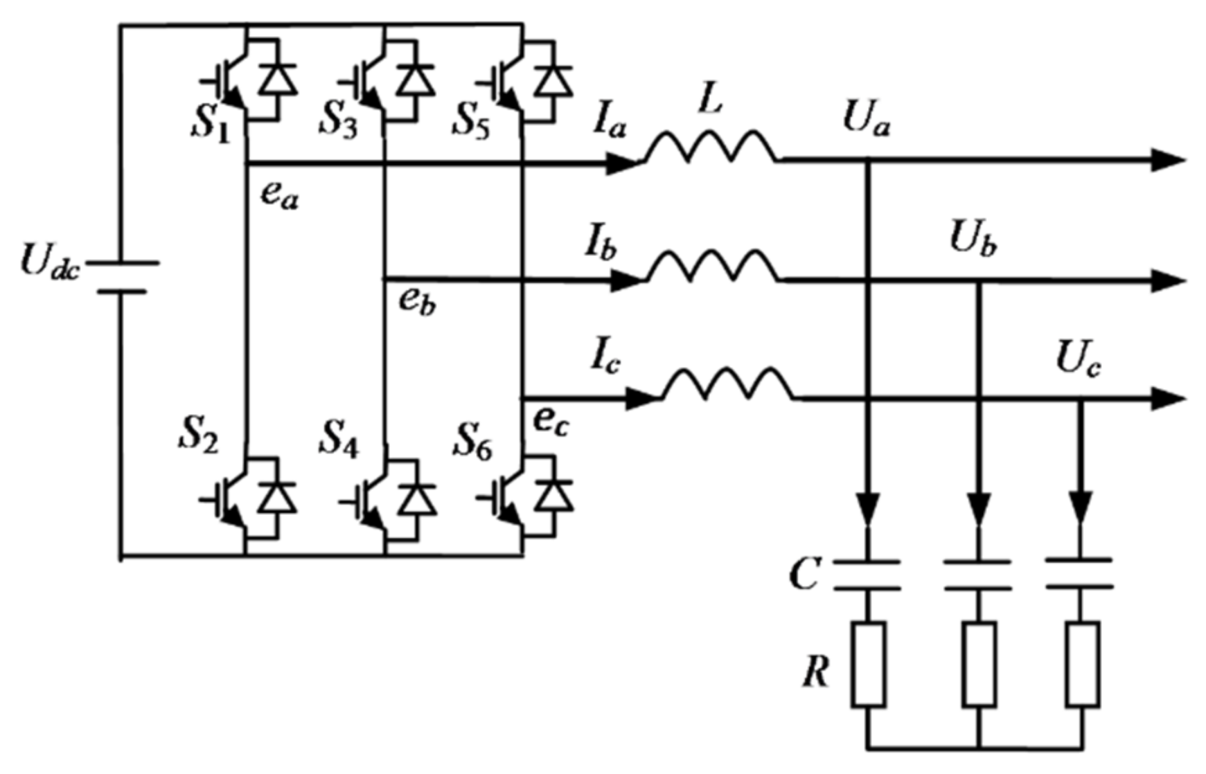
The main circuit of the inverter unit is shown in Figure 1. The Udc is the output of energy storage unit, and can be regarded as a constant voltage source. S1–S6 are the power switching device that forms the three-phase bridge inverter circuit.
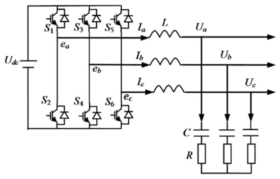
Figure 1.
Invertor unit.
When the invertor is regarded as VSG, the inductance of the bridge arm is regarded as the stator winding of the generator. So L, R, Ia, and Ua are a phase reactance, resistance, current, and voltage of stator winding, respectively. ea is the internal electric source of a phase of the generator, which can be expressed as E∠φ, E is the internal electromotive force, φ is the phase angle.
2.2. Virtual Stator Unit
According to the electromechanical coupling dynamics, the charge of capacitor ea-c, eb-c and ec-c are the generalized displacement, then current Iabc= [Ia Ib Ic]T are the generalized velocity. The energy of VSG include magnetic energy Wm = L(Ia2 + Ib2 + Ic2), electric field energy We = (ea-b2 + ea-c2 + eb-c2)/(2C), and dissipated energy Fd = R(Ia2 + Ib2 + Ic2)/2. The voltage of line Eabc is regarded as an external force. The Lagrange function of VSG is L = Wm − We, and then the Lagrange equation is
Noted to Uabc= ∂We/∂eabc-c, Equation (1) can be expanded as follows.
Equation (2) is the terminal voltage equation of VSG.
Considering eabc-c= CUabc, variables eabc-c in the electric field energy We are replaced by Uabc. Using the Xad basic value system and the Park transformation, and ignoring the 0 axis component, the generalized velocity selected as udq= [ud uq]T, then the Lagrange function of the stator in per unit is:
where XL and XC are the reactance of inductance and capacitance converted into d, q coordinate in per unit, id, iq, ud, and uq are current and voltage of stator d, q axis in per unit.
Equation (2) can be transformed into a normalized form of the d, q axis as follows.
2.3. Virtual Excitation Unit
The excitation system of VSG can be simplified as a first-order link as follows.
where ∆E = E − E0 is the increment of internal electric potential in per unit, E and E0 is the electromotive force and its initial value in per unit, uref and ut is the reference voltage and terminal voltage in per unit, KE is the gain coefficient, TE is the time constant of excitation.
The virtual excitation unit is constructed by combining the droop control of reactive power which is Qref − Q = −bQ(uref − ut). So the differential equation of excitation concluding droop control of reactive power can be expressed as follows.
where ZQ = idcosφ − iqsinφ, Q and Qref are the reactive power of VSG and its reference value in per unit, respectively, uref is the reference value of voltage in per unit, bQ is the droop coefficient of reactive power.
2.4. Rotor of VSG
While an inverter is constructed according to a virtual generator, the virtual generator with the salient pole effect ignored, one magnetic pole logarithm is adopted. A similar generator motion equation is
where TB is the inertia time constant of VSG in (s), pm is the mechanical power in per unit, pe is the active power in per unit, D is the damping coefficient, ω is the angular velocity in per unit.
The mechanical power of the invertor is obtained from droop control of active power, that is pref − pm = − bp(ωref − ω) where pref and ωref are reference value of active power and angular velocity in per unit, respectively, bp is the droop coefficient of active power.
The Equation (7) can be transformed as follows.
In the next section, it can be seen that this transformation can ensure the full rank of the input matrix and satisfy the transformation required in Hamiltonian structure modification.
2.5. Structure of VSG
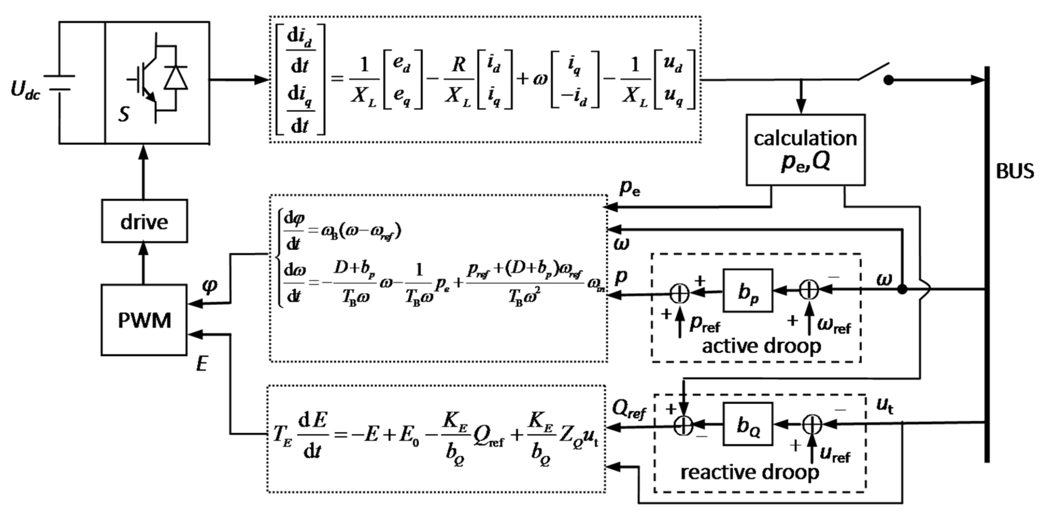
From what has been discussed above, the framework structure of VSG can be constructed as Figure 2.
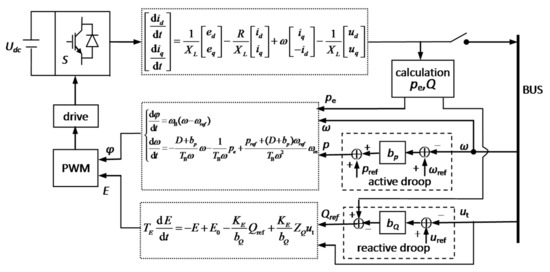
Figure 2.
VSG framework.
In Figure 2, the PWM and drive are execution units of VSG. VSG controls active power and reactive power output of the invertor according to changes of bus frequency and voltage and maintains the stability of bus frequency and voltage.
3. Hamiltonian Model of VSG
3.1. Hamiltonian Function
- (1)
- Virtual stator unit
According to the Hamiltonian principle, the generalized momentum is defined as pd = ∂L/∂id and pq = ∂L/∂iq, then the Hamiltonian function is . The Hamiltonian function of the virtual stator unit can be obtained from the Lagrange function Equation (3).
- (2)
- Virtual excitation unit
The basic form of the virtual excitation unit is given in Equation (5). The transfer function of Equation (5) can be simulated by a classic RC circuit, where the electric energy of capacitance can be regarded as a Hamiltonian function [37]. Therefore, Hamiltonian function of virtual excitation unit can be obtained as follows.
- (3)
- Virtual rotor unit
The energy of the rotor unit is the inertia potential energy. According to the Hamiltonian principle, the inertia potential energy of the rotor is transformed from Lagrange to Hamiltonian, and the form of the Hamiltonian remains same. The Hamiltonian function of the virtual rotor unit is
- (4)
- Hamiltoni an function of VGS
The Hamiltonian function of VSG is equal to the sum of the energies of the stator, rotor, and excitation, that is
3.2. Hamiltonian Model of VSG
There are transformation relationships based on the Hamiltonian function ∂H/∂φ = pe, ∂H/∂ω = TBω, ∂H/∂id = XLid, ∂H/∂iq = XLiq, and ∂H/∂E = TE(E − E0). These Hamiltonian transformations can be used to replace state variables, and then differential equation can be written as Hamiltonian equation.
The Equation (4) can be rewritten as
VSG adopts d-axis voltage orientation, that is eq = 0, ed = E. Considering the input control term is the bus voltage, denoted as utin. This treatment is to keep Equation (13) in an affine nonlinear equation form. In the network operation of the inverter, inverter outlet voltage ut is equal to the voltage of the connected bus utin. Ignoring the salient pole effect of VSG and the line reactance, so Xq∑ = Xd’∑ = X,ud = utsinφ, uq = utcosφ.
The Equation (8) can be rewritten as
Referring to the traditional third-order generator model, d, q axis current is id = (E − utcosφ)/XL and iq = utsinφ/XL. In the Hamiltonian function, id and iq imply the rotor variable φ, and the partial derivative of the implicit function is ∂H/∂φ = pe.
From the principle of VSG, the bus frequency is the input controllable variable, denoted as ωin. To keep Equation (14) in the form of affine nonlinear equation, in the last item of Equation (14), ωin is approximately replaced by ω. Since the angular frequency changes very little in the connect-grid operation condition, this approximation makes the reference power term of VSG have some errors in the transient process, but the errors will not be too large. When it enters the steady state, ω = ωin, the errors are eliminated.
The Equation (6) can be rewritten as
From the above transformation processes, they are all equivalent transformations based on differential equations. Therefore, the corresponding differential equations and Hamiltonian equations are mathematically equivalent.
Selected variables x = [φ ω id iq E]T, Equations (13)–(15) can be written in unification form. Considering matrix transformation J(x) = [T(x)−TT(x)]/2 and R(x) = −[T(x) + TT(x)]/2, the standard form of the generalized Hamiltonian system can be obtained as follows.
J(x) is the antisymmetric structure matrix, R(x) is the symmetric damping matrix, g(x) is the control input channel matrix, u is the input matrix, which includes bus frequency ωin and bus voltage utin.
4. Structure Modification of Hamiltonian
4.1. Basic Theory
Antisymmetric matrix Ja(x) is used to modify the structure matrix, Jd(x) = J(x) + Ja(x), and JTa(x) = −Ja(x), where symmetric matrix Ra(x) is used to modify the damping matrix, Rd(x) = R(x) + Ra(x), and RTa(x) = Ra(x). Then the equivalence transformation of Hamiltonian system (16) can be given as follows.
The above equation shows that, under appropriate conditions, the equivalent control w can be used to equivalent the change of The Hamiltonian structure, which is also the essence of the control design of Hamiltonian structure modification. The following equivalent transformations must be satisfied.
Multiply both sides of the Equation (18) gT(x). If the g(x) is column full rank matrix, then gT(x)g(x) is reversible, so
α is the additional control generated by the Hamiltonian structure modification.
In the Hamiltonian Equation (16), if u is replaced by w, it is mathematically equivalent to modifying the structure [Ja(x) − Ra(x)], because of the existence of additional control α.
4.2. Damping Injection
The stability of frequency and voltage are the key indexes of the isolated microgrid. However, there is no relevance between mechanical and electrical in the Hamiltonian system (16). This section attempts to increase the damping correlation between the bus voltage and the frequency so that the frequency and the voltage fluctuation are mutually restricted to better improve the stability of the isolated micro-grid. In the Hamiltonian model, the state variable x2 is the angular velocity ω, and the state variable x5 is the excitation electromotive force E. To increase the damping correlation between the ω and E, the corresponding position of the structure and the damping matrix is modified. Let Ja(x) = 0,Ra(x) is
According to Equation (20), the additional control can be obtained as
where , .
When the additional control could be calculated by Equation (20), g(x) must be column full rank matrix, so gT(x)g(x) satisfies the reversible condition. This is why the transformation form of Equation (8) is adopted.
5. Simulation Experiment
5.1. Simulation System
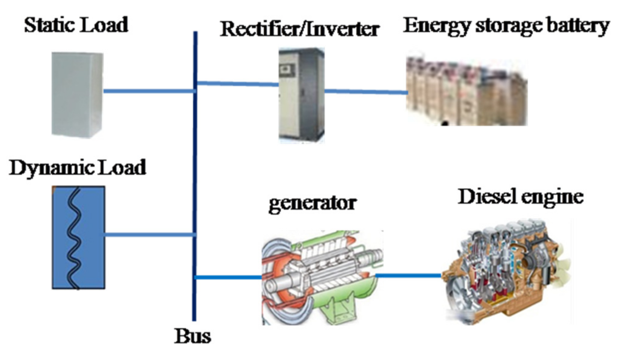
The isolated microgrid is shown in Figure 3.
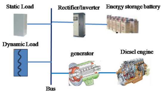
Figure 3.
Isolated micro grid.
In Figure 3, parameters of diesel generator sets (DGS), invertor unit, static load and dynamic load are all converted with power basic value of DGS. The model of dynamic load is the electromechanical transit model of electromotor [38], in which the active power of each motor is 0.1 pu and the reactive power is 0.047 pu. The change of dynamic load is simulated by the different numbers of electromotor.
The main parameters of the DGS: active power 1250 kW, rated speed n = 1500 r/min, m1 = 0.8 kg, mechanical damping coefficient c1 = 10.0 N.s/mm, spring stiffness k1 = 3.6, the maximum stroke of the shaft output 10 mm, the moment of inertia J = 71.822 kg·m2, the number of poles p = 2, and equivalent damping coefficient D = 2.1753. DGS use the traditional PID control, which the governor PID parameters are KP = 2.0, KI = 2.0, KD = 0.1, excitation PID parameters are KP = 2.0, KI = 2.0, KD = 0.1.
Using the Hamiltonian differential model of VSG replaced theinverter unit in the simulation calculation. LetD = 2, bP = 10, and bQ = −35.
Initial operation conditions: active power of DGS is 0.8 pu, reactive power of DGS is 0.6 pu; active power and reactive power of invertor are 0.0, the inverter works in a standby state; electromotors put in operation with active power 0.7 pu, reactive power 0.3291 pu. Other power is balanced by static loads to ensure the initial balance of bus power.
Simulation case: at t = 0.5 s, the motor is put into operation to simulate the nonlinear load mutation, the active power step is 0.1 pu, and the reactive power step is 0.047 pu.
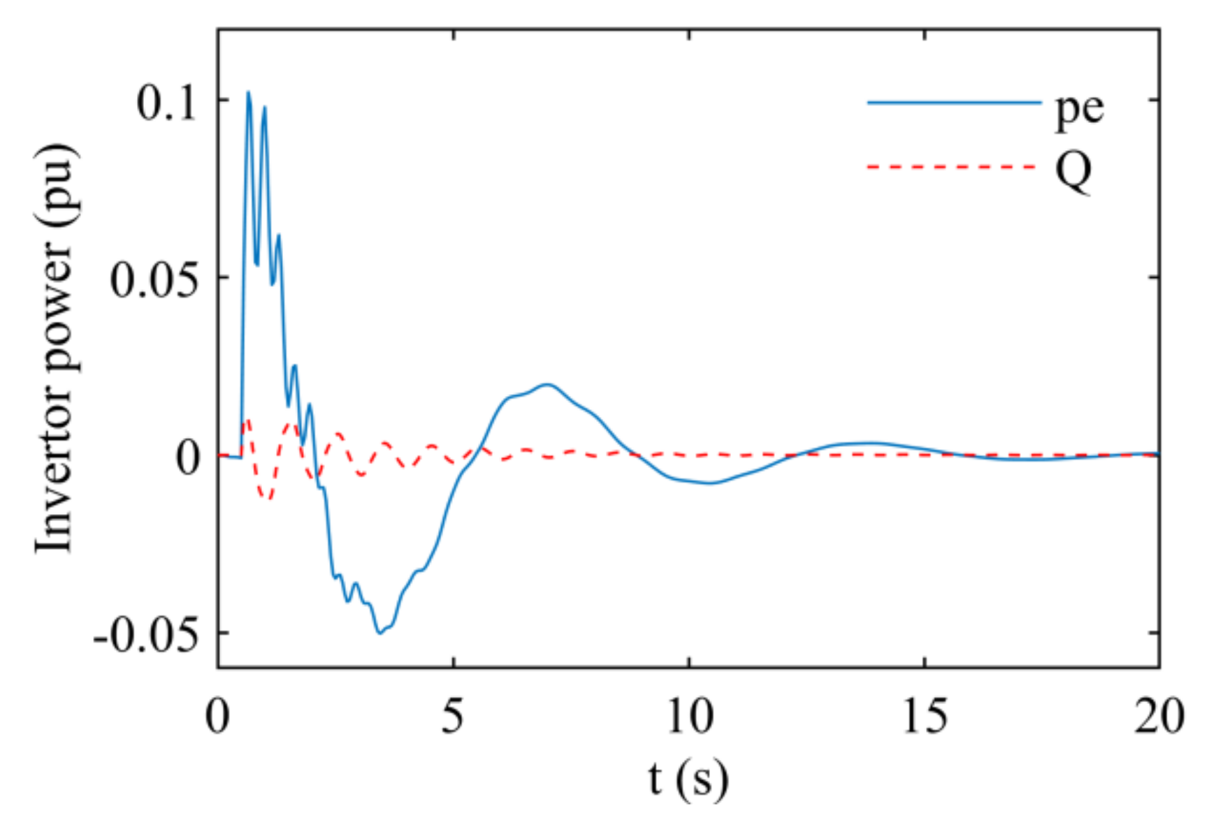
The power changes of the invertor are shown in Figure 4.
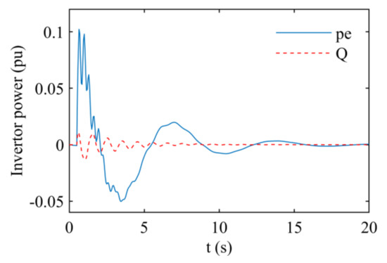
Figure 4.
Power changes of invertor in transient.
When loads change suddenly, the invertor supplies the power vacancy rapidly due to the regulation lag of DGS. After the regulation of DGS is finished, the invertor operates at a standby state, in which active power and reactive power of output are zero. Figure 4 reflects such an operation mode of invertor in the isolated microgrid.
5.2. Damping Characteristic Analysis
- (1)
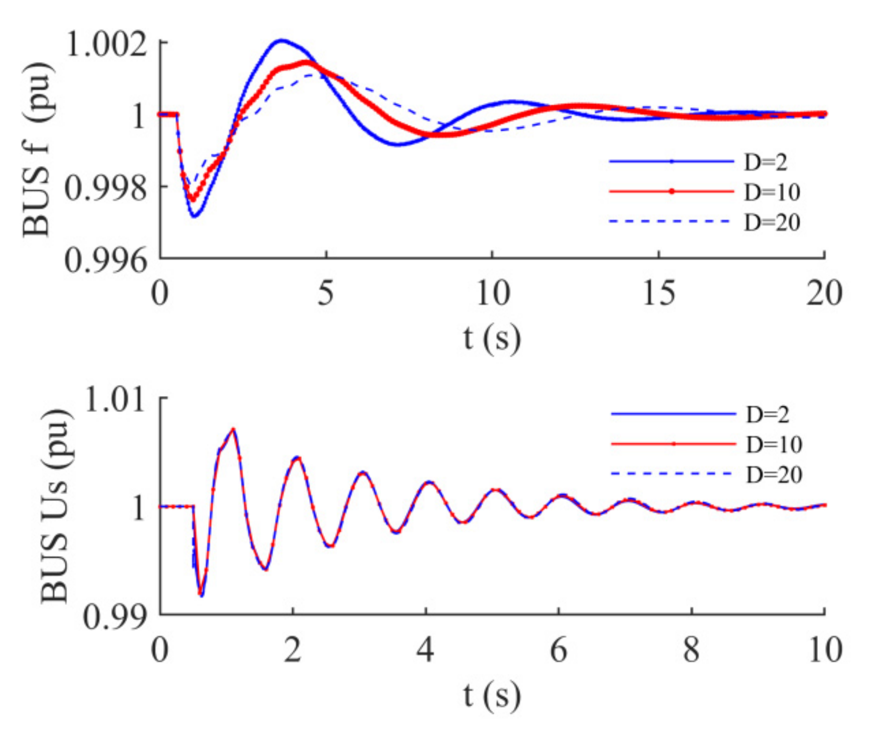
- The damping coefficient D of VSG is located in row 2 and column 2 of damping matrix R(x), which represents the corresponding state variable of angular velocity. From the view of dynamics, the position that the factor located is self-correlation damping of angular velocity, on which only the damping characteristics of angular velocity have an effect. As the damping coefficient D increases, the oscillation amplitude of bus frequency decreases and the attenuation speeds up. In other words, the damping of angular frequency oscillation increases, while the change of bus voltage is not obvious. See Figure 5.
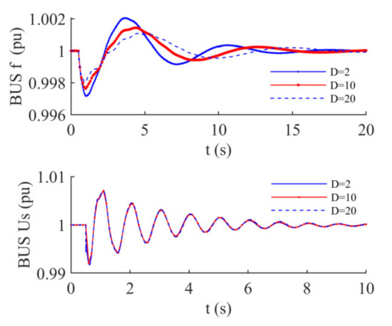 Figure 5. Effect of damping coefficient on bus frequency and voltage.
- (2)
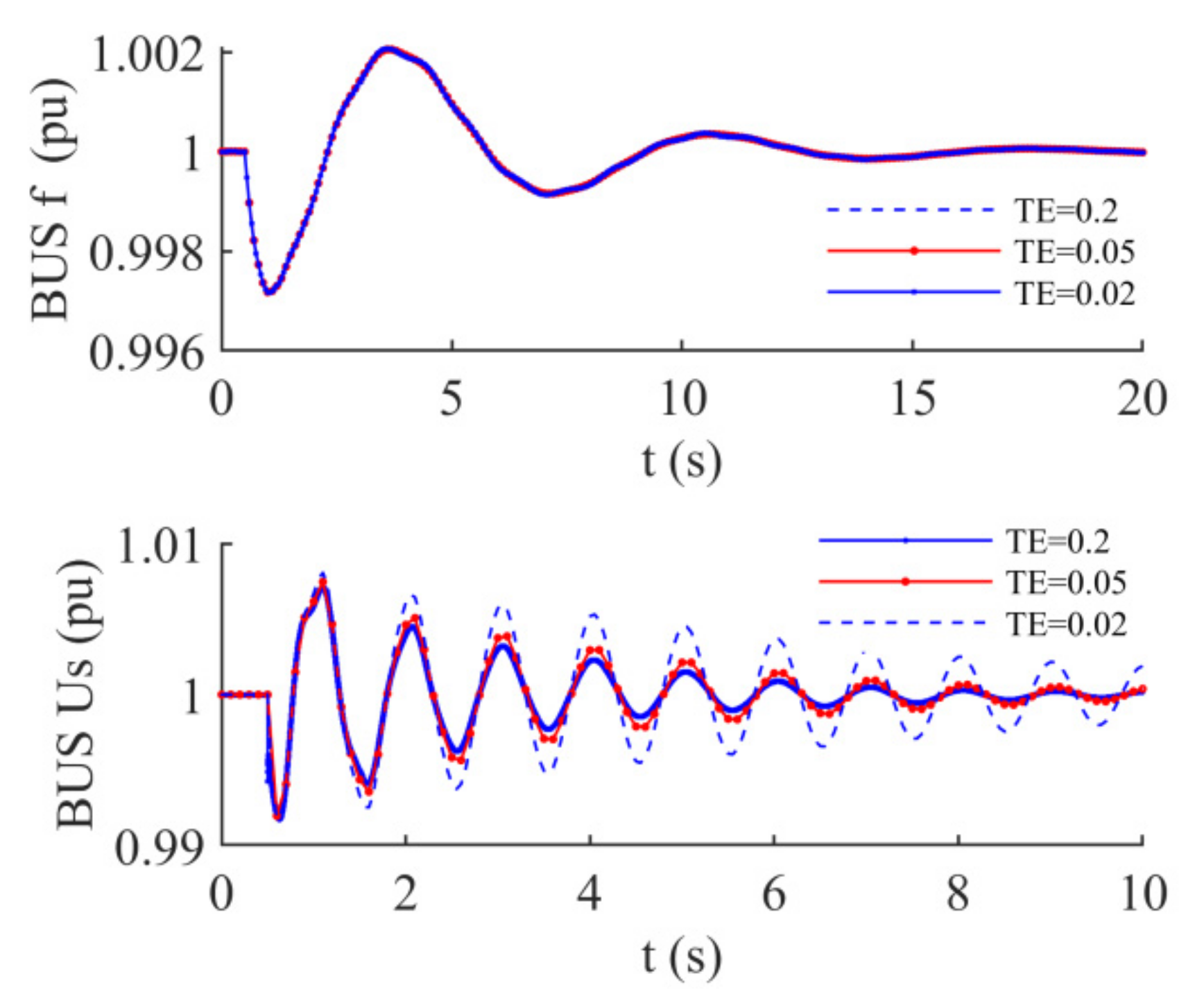
- The time constant of excitation TE relates to the state variables x3 and x5 in damping matrix R(x). Form the view of dynamics, where the element located at row 5 and column 5 is self-correction damping factor of x5, where the element located at row 3 and column 5 is cross-correction damping factor of x3 and x5. Therefore, the change of TE would affect the damping oscillation characteristics of bus voltage. Given different TE, the change of bus frequency and voltage is shown in Figure 6.
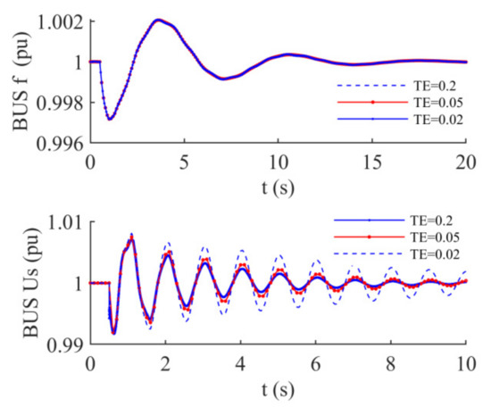 Figure 6. Effect of TE on bus frequency and voltage.
When TE decreases, the item in the damping matrix increases, and the bus voltage oscillation amplitude increases, which is equivalent to the decrease in the bus voltage oscillation damping. The value of TE has positive damping property. Figure 6 also shows that different TE given has little effect on the change of bus frequency.
Further simulation shows that TE < 0.2, the value of TE has little effect on the bus voltage, so it is not feasible to further increase the voltage oscillation damping by increasing TE.
- (3)
- Effect of active power droop coefficient
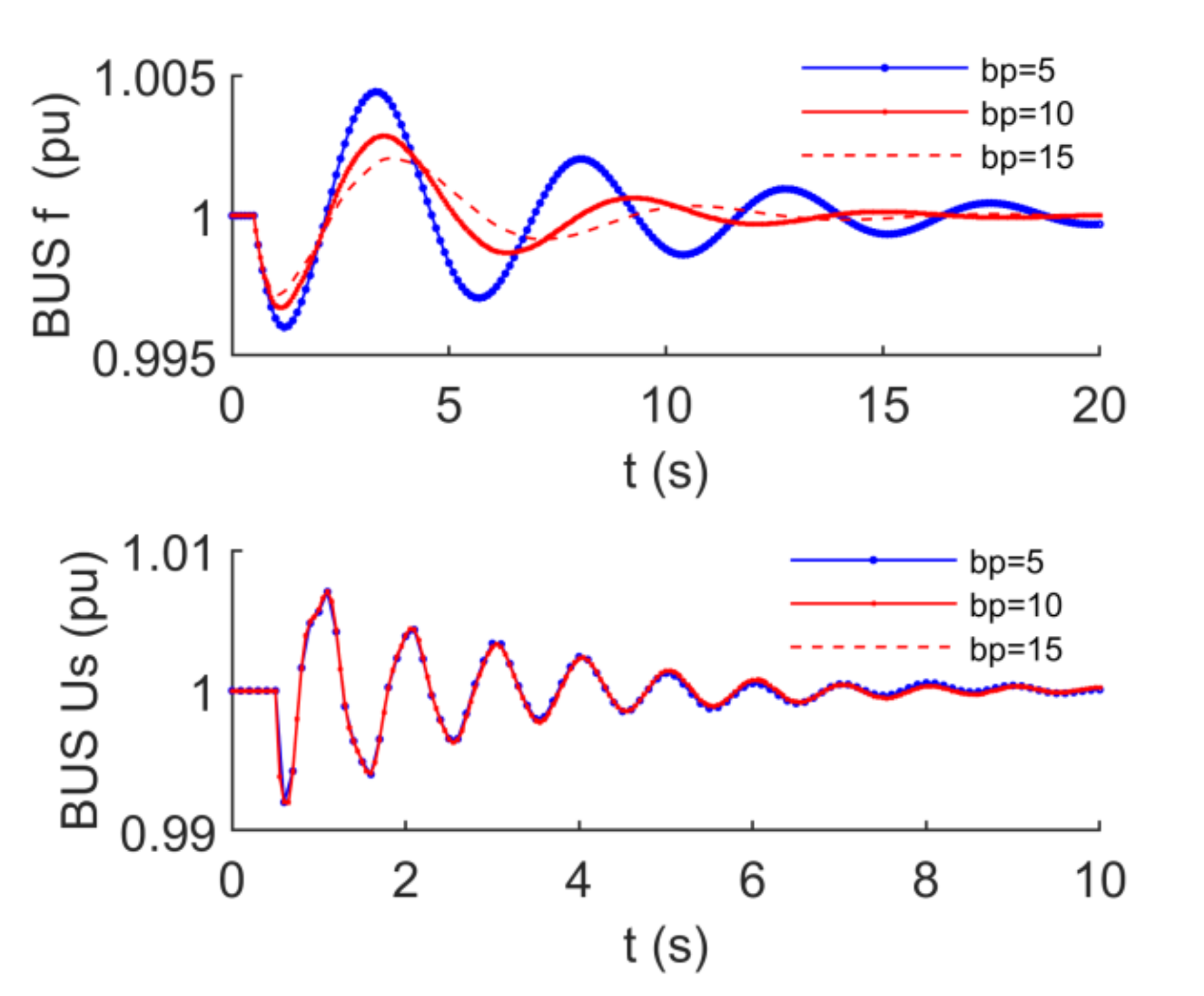
The active power droop coefficient bp is located at the same position with the damping coefficient in the damping matrix R(x), which means that the bp has the same characteristics with damping coefficient. Given different bp values, the changes of bus frequency and voltage are shown in Figure 7.
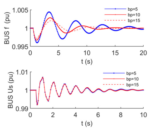
Figure 7.
Effect of active power droop coefficient on bus frequency and voltage.
Figure 7 shows that the effect of droop coefficient bp on oscillation damping of bus frequency is large. Its role is equivalent to the damping coefficient. However, the effect of bp on the oscillation of bus voltage can be ignored. The result is consistent with revealing by Hamiltonian structure dynamic.
5.3. Damping Injection Control
In the damping matrix of the Hamiltonian model, the correlation factor r25 relative to the angular velocity ω and the excitation electromotive force E is added. After the damping correlation is added, the equivalent control corresponding to the structure modification is calculated by Equation (20).
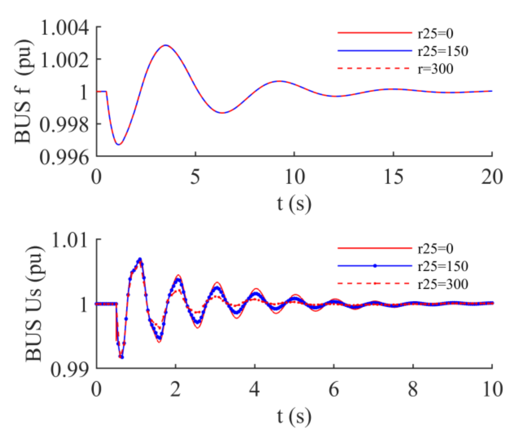
Let the inverter damping coefficient D = 2, TE = 0.2. Simulation analysis is carried out under the same simulation condition. The bus voltage and frequency changes under different values of r25 are shown in Figure 8.
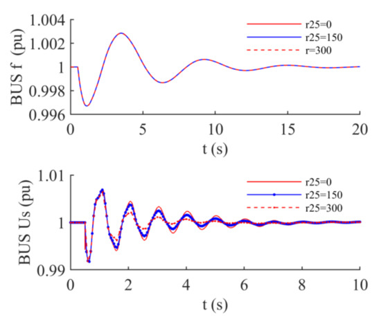
Figure 8.
Effect of relevance factor r25 on bus frequency and voltage.
In Figure 8, the bus frequency is little affected by the value of r25. From the damping modification additional control substituting the initial steady state data of the simulation condition into the damping modification additional control (20), the coefficient of the additional control item of the angular velocity in the first row is 1.7896 × 10⁻⁵. It is because this coefficient is very small, the structure modification has little influence on the angular frequency change when the given r25 is not very large. The damping correlation correction does not affect the change of the angular frequency, which is equivalent to get rid of the constraint of the angular frequency, and provides convenience for the selection of r25 to improve the bus voltage oscillation.
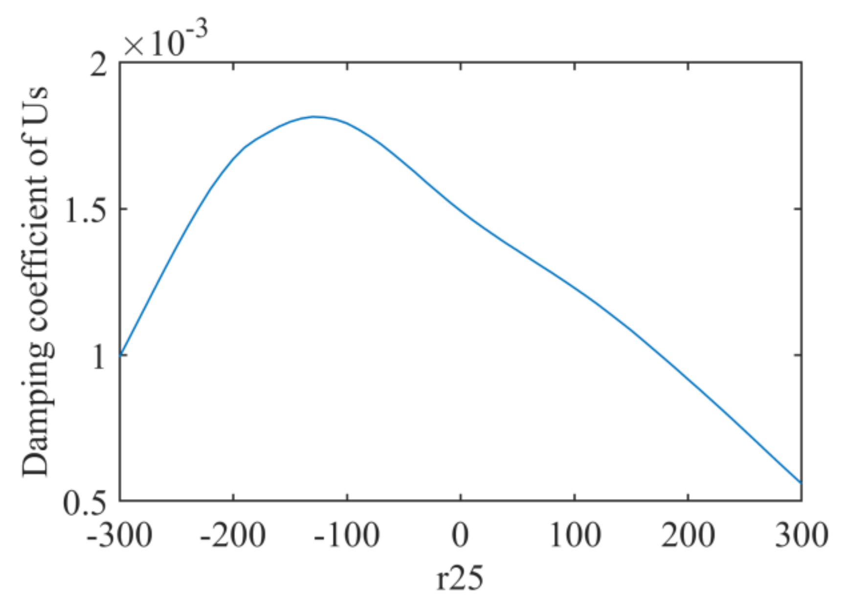
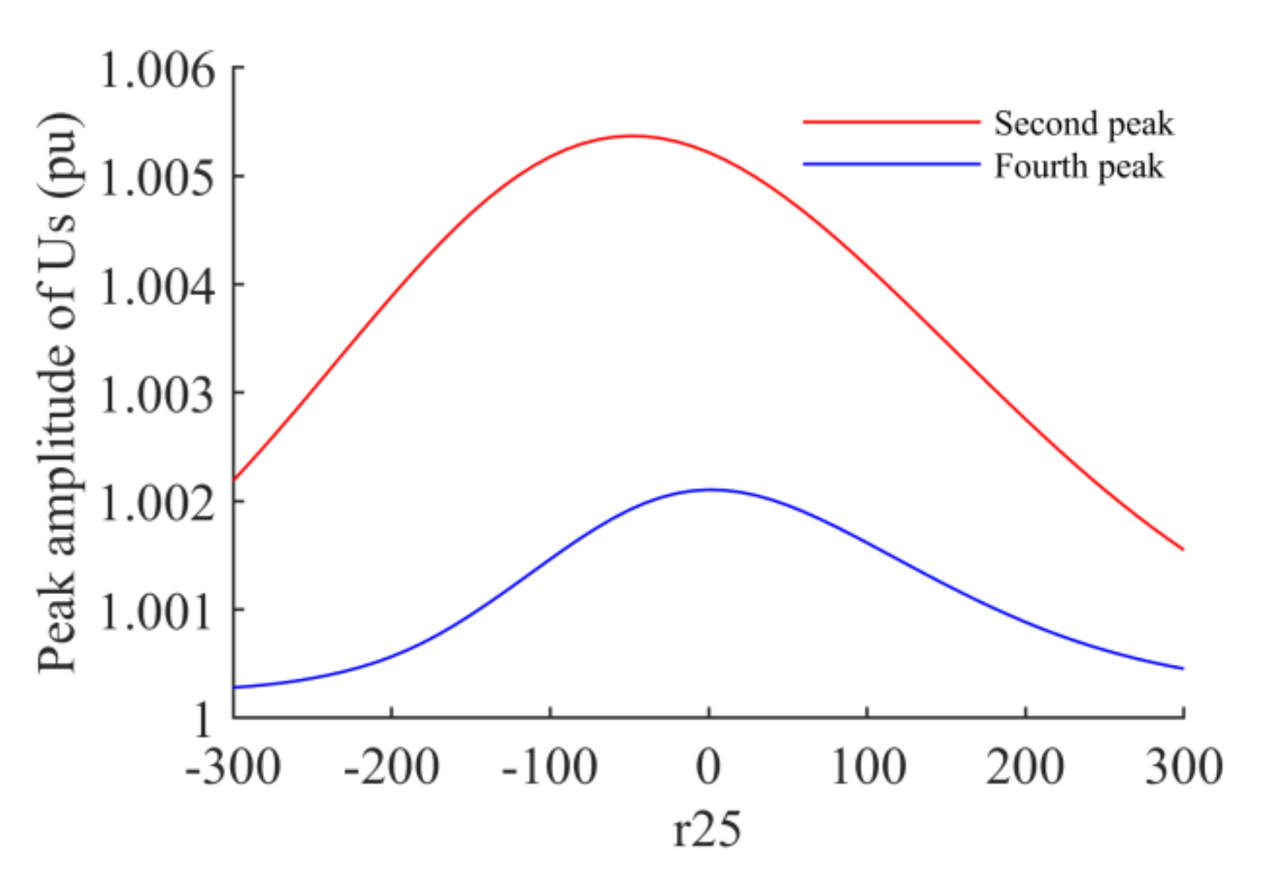
In Figure 8, the bus voltage oscillation attenuation varies greatly, and the attenuation varies with different values of r25, especially the voltage fluctuation amplitude changes greatly. Therefore, the change of bus voltage oscillation damping coefficient with different values of r25 is further studied, so the third and fourth peak values of voltage fluctuation are selected to investigate the change of amplitude as follows.
Figure 9 and Figure 10 show that the damping correlation factor r25 in an appropriate range can increase the damping of voltage oscillation and reduce the amplitude of voltage fluctuation. Its trend seems that the larger the value of r25 is, the smaller the oscillation amplitude will be. However, the further simulation shows that if r25 continues to increase, the off-beat phenomenon of voltage oscillation will occur, and the further increase will eventually lead to instability.
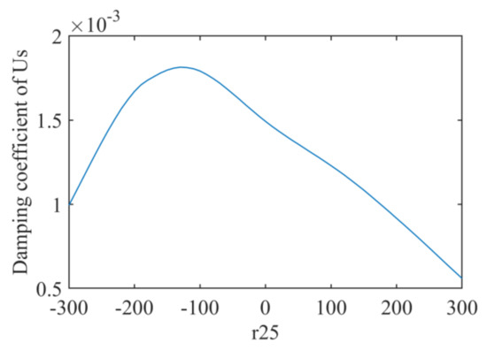
Figure 9.
Damping coefficient of bus voltage oscillation changes with r25.
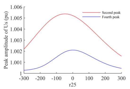
Figure 10.
Peak value of bus voltage oscillation change with r25.
6. Conclusions
In this paper, the Hamiltonian model of VSG is established. The damping formation mechanism and damping injection control of VSG are analyzed from the perspective of dynamics, and the isolated microgrid is constructed for simulation analysis. There are three conclusions as follows:
- (1)
- When the VSG is directly connected to the isolated microgrid bus, the influence of a single parameter of VSG on the oscillation damping of the bus voltage and frequency has decoupling characteristics, that is, the change of damping coefficient D and active power droop coefficient bp only affects the oscillation damping of the bus frequency; The excitation time constant TE of VSG only affects the bus voltage oscillation damping. This decoupling characteristic greatly facilitates the design of virtual generator parameters.
- (2)
- The Hamiltonian damping injection control design method proposed in this paper can effectively reduce the bus voltage fluctuation amplitude by selecting an appropriate damping factor, which can make up for the deficiency of small virtual generator time constant TE in reducing the bus voltage oscillation amplitude.
- (3)
- The Hamiltonian structure design method for VSG is a new approach. In this paper, the damping injection control is just an example. Further research can be carried out from the following aspects: the modified structure matrix, damping matrix, the single factor, and multiple factors to obtain more dynamic information and provide more means for control design.
Author Contributions
Conceptualization, Y.Z.; methodology, Y.Z. and J.Q.; software, H.M. and S.Y.; validation, J.Q. and F.Y.; formal analysis, F.Y.; investigation, F.Y.; resources, J.Q.; data curation, H.M. and S.Y.; writing—original draft preparation, Y.Z. and J.Q.; writing—review and editing, J.Q. and F.Y.; supervision, J.Q.; project administration, Y.Z.; funding acquisition, J.Q. and Y.Z.; All authors have read and agreed to the published version of the manuscript.
Funding
This research was funded by the National Natural Science Foundation of China, grant number 51869007. 52079059.
Institutional Review Board Statement
Not applicable.
Informed Consent Statement
Not applicable.
Data Availability Statement
Not applicable.
Conflicts of Interest
The authors declare no conflict of interest.
References
- Bevrani, H.; Ise, T.; Miura, Y. Virtual synchronous generators: A survey and new perspectives. Electr. Power Energy Syst. 2014, 54, 244–254. [Google Scholar] [CrossRef]
- Karapanos, V.; Sjoerd de Haan, S.D.; Zwetsloot, K. Real time simulation of a power system with VSG hardware in the Loop. In Proceedings of the IEEE IECON2011-37th Annual Conference of the IEEE Industrial Electronics Society, Melbourne, VIC, Australia, 7–10 November 2011; pp. 3748–3754. [Google Scholar]
- Chen, Y.; Hesse, R.; Turschner, D.; Beck, H.-P. Improving the grid power quality using virtual synchronous machines. In Proceedings of the 2011 International Conference on Power Engineering, Energy and Electrical Drives, Torremolinos, Spain, 11–13 May 2011; pp. 1–6. [Google Scholar]
- Hirase, Y.; Abe, K.; Sugimoto, K.; Shindo, Y. A grid connected inverter with virtual synchronous generator model of algebraic type. Electr. Eng. Jpn. 2013, 184, 10–21. [Google Scholar] [CrossRef]
- Sakimoto, K.; Miura, Y.; Ise, T. Stabilization of a power system with a distributed generator by a virtual synchronous generator function. In Proceedings of the IEEE 8th International Conference on Power Electronics and ECCE Asia (ICPE & ECCE), Jeju, Korea, 30 May–3 June 2011; pp. 1498–1505. [Google Scholar]
- Soni, N.; Doolla, S.; Chandorkar, M.C. Improvement of transient response in microgrids using virtual inertia. IEEE Trans. Power Deliv. 2013, 28, 1830–1838. [Google Scholar] [CrossRef]
- Liu, J.; Miura, Y.; Ise, T. Comparison of dynamic characteristics between virtual synchronous generator anddroop control in inverter-based distributed generation. IEEE Trans. Power Electron. 2016, 31, 3600–3611. [Google Scholar] [CrossRef]
- Haritha, M.S.; Nai, D.S. Review on Virtual Synchronous Generator (VSG) For Enhancing Performance Of Microgrid. In Proceedings of the 2018 International Conference on Power, Signals, Control and Computation (EPSCICON), Thrissur, India, 6–10 January 2018. [Google Scholar]
- Shi, K.; Haihan, Y.; Song, W.T.; Zhou, G.L. Virtual Inertia Control Strategy in Microgrid Based on Virtual Synchronous Generator Technology. IEEE Access 2018, 6, 27949–27957. [Google Scholar] [CrossRef]
- Liu, J.N.; Hossain, M.J.; Lu, J.W.; Rafi, F.H.M.; Li, H. A hybrid AC/DC microgrid control system based on a virtual synchronous generator for smooth transient performances. Electr. Power Syst. Res. 2018, 162, 169–182. [Google Scholar] [CrossRef]
- Shi, K.; Song, W.T.; Ge, H.L.; Xu, P.F.; Yongheng Yang, Y.H.; Blaabjerg, F. Transient Analysis of Microgrids With Parallel Synchronous Generators and Virtual Synchronous Generators. IEEE Trans. Energy Convers. 2020, 35, 95–105. [Google Scholar] [CrossRef]
- Zheng, T.; Chen, L.; Guo, Y.; Mei, S. Omprehensive control strategy of virtual synchronous generator under unbalanced voltage conditions. IET Gener. Transm. Distrib. 2018, 12, 1621–1630. [Google Scholar] [CrossRef]
- Liu, J.; Miura, Y.; Bevrani, H.; Ise, T. Enhanced Virtual Synchronous Generator Control for Parallel Inverters in Microgrids. IEEE Trans. Smart Grid 2017, 8, 2268–2277. [Google Scholar] [CrossRef]
- Nian, H.; Jiao, Y. Improved Virtual Synchronous Generator Control of DFIG to Ride-Through Symmetrical Voltage Fault. IEEE Trans. Energy Convers. 2020, 35, 672–683. [Google Scholar] [CrossRef]
- Nguyen, C.; Nguyen, T.; Yoo, H.; Kim, H. Improving Transient Response of Power Converter in a Stand-Alone Microgrid Using Virtual Synchronous Generator. Energies 2018, 11, 27. [Google Scholar] [CrossRef] [Green Version]
- Hirase, Y.; Abe, K.; Sugimoto, K.; Sakimoto, K.; Bevrani, H.; Ise, T. A novel control approach for virtual synchronous generators to suppress frequency and voltage fluctuations in microgrids. Appl. Energy 2018, 210, 699–710. [Google Scholar] [CrossRef]
- Magdy, G.; Bakeer, A.; Nour, M.; Petlenkov, E. A new virtual synchronous generator design based on the SMES system for frequency stability of low-inertia power grids. Energies 2020, 13, 5641. [Google Scholar] [CrossRef]
- Cheng, H.; Shuai, Z.; Shen, C.; Liu, X.; Li, Z.; Shen, J. Transient Angle Stability of Paralleled Synchronous and Virtual Synchronous Generators in Islanded Microgrid. IEEE Trans. Power Electron. 2020, 35, 8751–8765. [Google Scholar] [CrossRef]
- Zhao, H.; Qiang, Y.; Zeng, H. Multi-loop virtual synchronous generator control of inverter-based DGs under microgrid dynamics. IET Gener. Transm. Distrib. 2017, 11, 795–803. [Google Scholar] [CrossRef]
- Hu, H.; Fu, F.; Wang, T.; Wan, X.; Ding, X. Optimization Control Strategy for Islanded Parallel Virtual Synchronous Generators. Math. Probl. Eng. 2020, 2020, 8971213. [Google Scholar] [CrossRef]
- Yuan, C.; Xie, P.; Yang, D.; Xiao, X. Transient Stability Analysis of Islanded AC Microgrids with a Significant Share of Virtual Synchronous Generators. Energies 2018, 11, 44. [Google Scholar] [CrossRef] [Green Version]
- El Tawil, T.; Yao, G.; Charpentier, J.; Benbouzid, M. Design and analysis of a virtual synchronous generator control strategy in microgrid application for stand-alone sites. IET Gener. Transm. Distrib. 2019, 13, 2154–2161. [Google Scholar] [CrossRef]
- Li, L.; Li, H.; Tseng, M.; Feng, H.; Chiu, A. Renewable Energy System on Frequency Stability Control Strategy Using VirtualSynchronous Generator. Symmetry 2020, 12, 1697. [Google Scholar] [CrossRef]
- Fathi, A.; Shafiee, Q.; Bevrani, H. Robust Frequency Control of Microgrids Using an Extended Virtual Synchronous Generator. IEEE Trans. Power Syst. 2018, 33, 6289–6297. [Google Scholar] [CrossRef]
- Shi, R.; Zhang, X.; Hu, C.; Xu, H.; Gu, J.; Cao, W. Self-tuning virtual synchronous generator control for improving frequency stability in autonomous photovoltaic-diesel microgrids. J. Mod. Power Syst. Clean Energy 2018, 6, 482–494. [Google Scholar] [CrossRef] [Green Version]
- Cheng, D.; Xi, Z.; Lu, Q.; Mei, S. Geometrical structure and application of generalized controlled Hamiltonian systems. Sci. China 2000, 30, 341–355. [Google Scholar]
- Ortega, R.; Van der Schaft, A.; Mareels, I.; Maschke, B. Putting energy back in control. IEEE Control Syst. 2001, 21, 18–33. [Google Scholar]
- Ortega, R.; Van der Schaft, A.; Castanos, F.; Astolfi, A. Control by interconnection and standard passivity-basedcontrol of port-Hamiltonian systems. IEEE Trans. Autom. Control 2008, 53, 2527–2542. [Google Scholar] [CrossRef] [Green Version]
- Wang, Y.; Cheng, D.; Hong, Y. Stabilization of synchronous generators with the Hamiltonian function approach. Int. J. Syst. Sci. 2001, 32, 971–978. [Google Scholar] [CrossRef]
- Ma, Y.; Lin, Z.; Yu, R.; Zhao, S. Research on Improved VSG Control Algorithm Based on Capacity-Limited Energy Storage System. Energies 2018, 11, 677. [Google Scholar] [CrossRef] [Green Version]
- Li, S.; Wang, Y. Robust adaptive control of synchronous generators with SMES unit via Hamiltonian function method. Int. J. Syst. Sci. 2007, 38, 187–196. [Google Scholar] [CrossRef]
- Bevrani, H. Robust Power System Frequency Control; Springer: New York, NY, USA, 2009. [Google Scholar]
- Lee, G.; Gui, Y.; Kim, C.; Chung, C. Direct Power Control for Three Phase Grid Connected Inverter via Port-Controlled Hamiltonian Method. In Proceedings of the Conference of the IEEE Industrial Electronics Society, Yokohama, Japan, 9–12 November 2015. [Google Scholar]
- Zeng, Z.; Yang, H.; Zhao, R.; Song, C. A Novel Control Strategy for Grid-Connected Inverters With LC Filter Based on Passive Hamiltonian Theory. Power Syst. Technol. 2012, 36, 207–212. [Google Scholar]
- Matthews, R.; Weaver, W.; Robinett, R.; David, G.; Wilson, D. Hamiltonian methods of modeling and control of AC microgrids with spinning machines and inverters. Electr. Power Energy Syst. 2018, 98, 315–322. [Google Scholar] [CrossRef]
- Cupelli, M.; Gurumurthy, S.; Bhanderi, S.; Yang, Z.; Joebges, P.; Monti, A.; De Doncker, R. Port Controlled Hamiltonian Modeling andIDA-PBC Control of Dual Active Bridge Converters for DC Microgrids. IEEE Trans. Ind. Electron. 2019, 66, 9065–9075. [Google Scholar] [CrossRef]
- Qian, J.; Zeng, Y.; Zhang, L.; Xu, T. Analysis on equivalence between transfer function and equivalent circuit simulation in general Hamiltonian modeling. In Proceedings of the 2012 International Conference on Civil, Architectural and Hydraulic Engineering (ICCAHE 2012), Zhangjiajie, China, 10–12 August2012. [Google Scholar]
- Kunder, P. Power System Stability and Control; McFraw-Hill: New York, NY, USA, 1994. [Google Scholar]
Publisher’s Note: MDPI stays neutral with regard to jurisdictional claims in published maps and institutional affiliations. |
© 2021 by the authors. Licensee MDPI, Basel, Switzerland. This article is an open access article distributed under the terms and conditions of the Creative Commons Attribution (CC BY) license (https://creativecommons.org/licenses/by/4.0/).

