Article

Optimal Configuration of the Integrated Charging Station for PV and Hydrogen Storage

College of Energy and Electrical Engineering, Hohai University, Nanjing 211100, China
*
Author to whom correspondence should be addressed.
Energies 2021, 14(21), 7087; https://doi.org/10.3390/en14217087
Submission received: 29 September 2021 / Revised: 18 October 2021 / Accepted: 25 October 2021 / Published: 29 October 2021

Abstract

:
This paper designs the integrated charging station of PV and hydrogen storage based on the charging station. The energy storage system includes hydrogen energy storage for hydrogen production, and the charging station can provide services for electric vehicles and hydrogen vehicles at the same time. To improve the independent energy supply capacity of the hybrid charging station and reduce the cost, the components are reasonably configured. To minimize the configuration cost of the integrated charging station and the proportion of power purchase to the demand of the charging station, the energy flow strategy of the integrated charging station is designed, and the optimal configuration model of optical storage capacity is constructed. The NSGA-II algorithm optimizes the non-inferior Pareto solution set, and a fuzzy comprehensive evaluation evaluates the optimal configuration.

1. Introduction

China is an enormous energy-consuming country, and most fossil fuels such as oil depend on imports [1]. The general use of fossil fuels has caused increasing air pollution and an energy crisis [2,3]. Therefore, renewable energy is quickly developed, especially photovoltaic power generation, wind power, storage hydrogen, and fuel cell [4,5,6], and used in related scenarios. Although renewable energy provides us with convenience, they also have some shortcomings. They are challenging to take advantage of due to the randomness of the effort [7]. A new application direction is to provide power for new energy vehicles [8,9]. New energy vehicles have become a vital travel tool because of their low dependence on traditional energy and green emission-free environmental protection [10]. With the rapid development of electric vehicles, charging facilities providing services have also been paid attention to. As the power grid purchase of charging stations also indirectly causes high carbon emissions, charging stations that consider the combination of distributed renewable energy have a bright future. The 14th five-year plan proposes to plan the future industry prospectively: organize and implement the future industry incubation and acceleration plan in frontier fields such as hydrogen energy and energy storage. Under the dual carbon goal, hydrogen energy as a clean energy future has been written into the development plan of 30 provinces.
Cheng et al. [11] proposed a double objective mathematical model that comprehensively minimizes charging station cost and the highest photovoltaic utilization rate, constrained by the range of decision variables, power balance, and energy storage variables. NSGA-II multi-objective genetic algorithm is used to optimize the configuration of the charging station. Zhang et al. [12] takes the load demand of electric vehicles as the premise, combined with the advantages of quasi energy storage performance of electric vehicle power station switching mode. It considers the multi-objective of minimum construction cost and minimum power shortage loss cost. The differential evolution algorithm solves the optimal configuration results of solar energy storage and charger capacity. Lu et al. [13] construct a hybrid copula function to describe the correlation between photovoltaic power generation and electric vehicle demand. Under the constraints of volatility and confidence, an improved invasive weed optimization algorithm based on differential evolution strategy is used to optimize the energy storage configuration. Sun and Li [14,15] considers the optimized cycle life of the battery in the optimal configuration to reduce the total cost and improve the utilization rate. Li et al. [16] proposed an optimization strategy of energy storage capacity of optical storage and charging station considering orderly charging of electric vehicles.
At present, the research on the optimal configuration of charging stations primarily focuses on the coordination and optimization between wind power generation, diesel generator, and battery energy storage and rarely takes hydrogen energy into account. Hydrogen has many advantages, such as clean and pollution-free, high combustion calorific value, and energy storage. If it can be used reasonably, it will have a high utilization value. This paper integrates hydrogen energy storage into charging stations, establishes two forms of energy flow, and establishes comprehensive charging stations that can serve EV and HV new energy vehicles. Firstly, the structure of the optical storage integrated charging station and the operation mode of each component is introduced. Secondly, the capacity flow strategy of the charging station is designed. Finally, according to the charging demand of electric vehicles and hydrogen fuel electric vehicles, the optimal optical storage capacity allocation model is constructed to minimize the integrated charging station’s operation cost and power purchase proportion. The NSGA-II algorithm optimizes the non-inferior Pareto solution set, and the component configuration is determined by fuzzy comprehensive evaluation.
The remainder of the paper is organized as follows. Section 2 introduces the structure of the integrated charging station and the operation mode of each component. Section 3 designs the capacity flow strategy and the optimization model. Section 4 describes the optimization model solution. Section 5 describes the cases. Finally, Section 6 concludes.

2. Structure and Component Mathematical Model of Integrated Charging Station

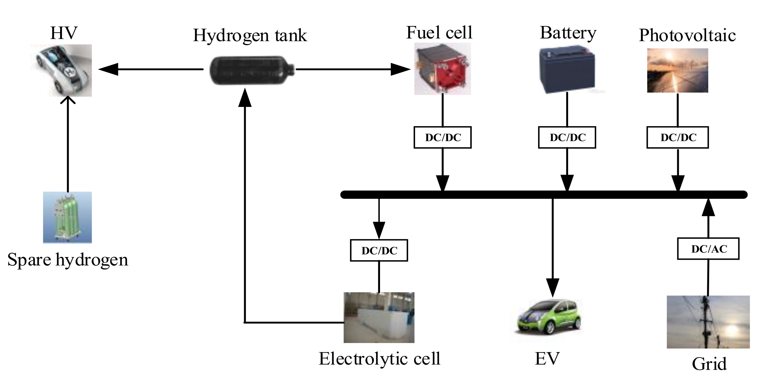
2.1. Structure of Integrated Charging Station

Structure of integrated charging station the system structure of the optical storage integrated charging station studied in this paper is shown in Figure 1. It mainly includes photovoltaic, battery, electrolytic cell, hydrogen tank, fuel cell, converter, etc.

2.2. Component Mathematical Model

Module mathematical model photovoltaic output power is related to many factors, mainly light intensity and ambient temperature. The output power formula is given as:
P p v = P p v S T C G T ( t ) G S T C ( 1 + ( T C T S T C ) )
where G T and T C each represent the sunlight intensity and the environmental temperature. Under standard conditions, the light intensity and temperature are 1 kilowatt per square meter and 25 centigrade, respectively. P p v S T C is the rated power of the photovoltaic board given by the supplier.
The charge state of the remaining charge and discharge is modeled as:
S O C ( t ) = S O C ( t 1 ) + η P B Δ t E B
where E B is the rated energy storage capacity, P B is the charging and discharging power of energy storage, η is the operating electrical efficiency of energy storage, and the time step is one hour.
The hydrogen energy storage system has two functions: on the one hand, it is the same as the battery, and on the other hand, it provides hydrogen load for hydrogen-fueled electric vehicles.
Hydrogen is produced by electrolyzing water with electric energy consumed for photovoltaic power generation. The hydrogen production formula is modeled as:
H w e = P w e η w e / H H V
where H w e is the output power of photovoltaic power generation for hydrogen production, η w e is the working efficiency of the electrolytic cell, and it takes 86%.
The hydrogen tank stores hydrogen at every moment. The use of electrolytic cells and the fuel cell is independent of each other. It can charge and discharge hydrogen simultaneously and conduct comprehensive modeling in combination with HV demand, unlike the battery. The time interval is one hour, and its hydrogen storage capacity is modeled as:
H ( t ) = H ( t 1 ) + H w e ( t 1 ) H l ( t 1 ) H f c ( t 1 )
H ( t ) = H 0 , t = 0
where H is the hydrogen content of the hydrogen storage tank, H l and H f c are the hydrogens provided to hydrogen fuel vehicles and fuel cells, respectively. The capacity of the hydrogen storage tank at the initial time is not equal to zero.
Fuel cells use hydrogen and oxygen as fuel to convert chemical energy into electrical energy for storage. The output power can be expressed as:
P f c = H f c η f c H H V
where P f c is the output power of electricity generated by burning hydrogen, and η f c is the working efficiency of the fuel cell, and it takes 60%.

3. Optimized Configuration Model

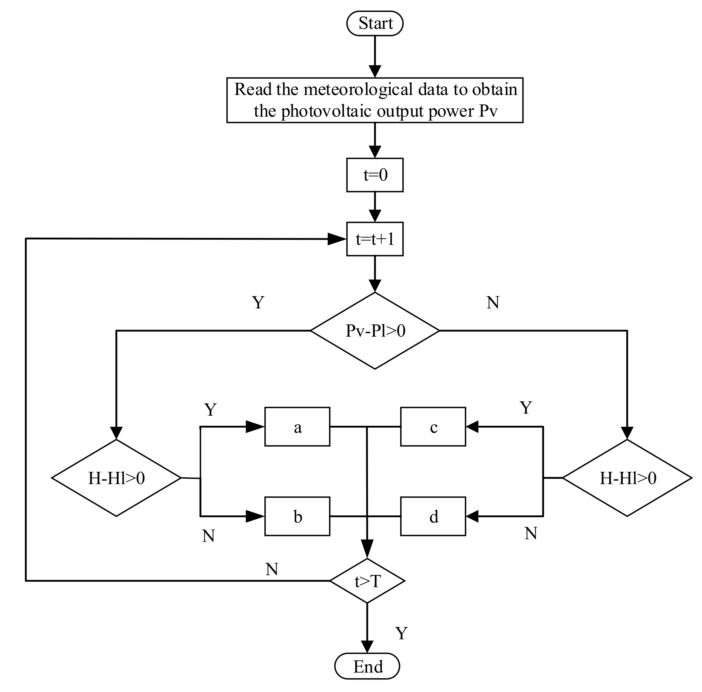
3.1. Energy Flow Strategy

The energy flow strategy of the integrated station affects the output between various components. The energy flow control strategy proposed in this paper is shown in Figure 2. For the difference between EV and HV demand of service, four operation strategies are specified to determine the operation of battery and hydrogen energy storage system:
a:
If the requirements of EV and HV are met., the remaining power of photovoltaic power generation will charge the battery in turn, the electrolytic cell will store hydrogen, and finally, the remaining power will be connected to the grid.
b:
If the requirements of EV are met, the requirements of HV are not met. The remaining power of photovoltaic power generation is first used for electrolytic hydrogen storage in the electrolytic cell. When used for battery charging, HV is still in shortage and is supplemented with purchased standby hydrogen.
c:
If the requirements of HV are met, the requirements of EV are not met. The primary discharge of battery and fuel cells provides the demand for EV, finally supplemented by the power grid.
d:
There is a shortage in EV and HV demand. The EV demand is discharged by the battery first, and the power grid will supplement the power shortage. HV needs to purchase a standby hydrogen supplement.

3.2. Optimization Model

This paper mainly studies the configuration of each component of the charging station. The optimization variables are the capacity of each component of the integrated charging station, photovoltaic, battery, and hydrogen energy storage system. The objective of optimized configuration mainly considers the economy and autonomous operation ability of the component configuration of the integrated charging station.
The first goal is that the system has the smallest operating cost, which includes the investment cost, maintenance costs, replacement costs, purchasing electricity costs, and sales of electricity consumption.
min F 1 = ( C 1 + C 2 ) C R F + C 3 C 4
C 1 and C 2 each represent the investment cost and maintenance cost of the configuration components, C 3 represents the operation cost of the total station, C 4 represents the income from selling electricity to the power grid, C R F represents the component annualized coefficient.
The investment cost is expressed as:
C 1 = P p v e p v + P b a e b a + P w e e w e + P f c e f c + H e H
where P p v , P b a , P w e , P f c are the installed capacity of the photovoltaic, battery, electrolytic cell, and fuel cell, respectively; H is the capacity of hydrogen tank; e p v , e b a , e w e , and e f c are the unit prices of corresponding components respectively.
Maintenance cost is expressed as:
C 2 = C 1 K
Represents the annual maintenance coefficient of the component, with a value of 0.1.
Running cost is expressed as:
C 3 = 365 ( t = 1 24 e H i H G ( t ) + t = 1 24 e G i P G i ( t ) )
The prices of electricity purchase and standby hydrogen purchase of e H i and e G i power grid. H G and P G i are the standby hydrogen and power purchased by the power grid in each period.
Income from surplus power on the grid is expressed as:
C 4 = 365 t = 1 24 e G o P G o ( t )
where P G o and e G o are on grid power and on grid electricity price respectively.
The expression for annualized coefficient is:
C R F = r ( 1 + r ) y ( 1 + r ) y 1
where r is the actual annual interest rate, taken as 4% in this paper [17], and y is the active life of the component.
Another goal is self-operative operation. Mainly, the purchase of electricity and hydrogen consumption in the mixed charging station accounts for the least customer demand.
min F 2 = n = 1 T P G i ( t ) n = 1 T P l ( t )
min F 3 = n = 1 T H G i ( t ) n = 1 T H l ( t )
Electric power balance constraint and hydrogen balance constraint are given as:
P l = P p v + P w e + P b a + P f c + P G
H l = H + H G + H w e H f c
Grid supply constraint is given as:
P G P G max
where P G max is the ultimate output power of the grid.
Energy storage state of charge constraint is given as:
S O C min S O C ( t ) S O C max
where S O C max , S O C min are the maximum and minimum state of charge of battery energy storage.

4. Optimization Model Solution

4.1. Optimize Process

In this paper, the optimization objective is to minimize the configuration investment and operation and maintenance cost of the integrated charging station and the energy purchase proportion. NSGA-II is one of the main algorithms [18]. NSGA-II algorithm is used to optimize each component’s configuration gradually, and a set of Pareto optimal solutions is obtained. The specific optimization process is as follows: initial parameter value setting, population initialization, fast non dominated sorting, calculation of virtual fitness, selection, crossover and mutation, elite strategy, and repeated sudden cycle to the end of the iteration. The specific process is shown in Figure 3.

4.2. Fuzzy Comprehensive Evaluation

After the Pareto optimal frontier is finally obtained through the optimization process, it is necessary to screen the optimized multi-group configuration schemes. In this paper, the fuzzy comprehensive evaluation method is used to select the optimal configuration scheme. The fuzzy membership function is used to calculate the membership of each Pareto solution. The optimization scheme with the highest membership is the optimal compromise Scheme [19].
Firstly, the membership function of a single target is determined. As the more negligible the optimization target, the better the smaller trapezoidal distribution is selected. The membership degree of each function value is solved to obtain the fuzzy comprehensive evaluation matrix. Secondly, the weight of each evaluation index is calculated by the entropy weight method. Finally, the evaluation results are obtained by the weight set and fuzzy comprehensive evaluation matrix, and the optimal solution corresponding to the value with the highest membership degree is selected.
u n m = 1 F n m < F n min F n max F n m F n max F n min F n min F n m F n max 0 F n m > F n max
where F n m and u n m are the function value and membership of the m non-inferior solution of the n objective function, respectively.

5. Example Analysis

5.1. Scene and Parameters

The capacity of a charging station built and operated in a particular place is configured to establish a comprehensive charging station for light and hydrogen storage. The light intensity data and the daily demand of two types of new energy vehicles are selected as the data. Taking one year of operation of the comprehensive station as the cycle, calculate the component investment of the comprehensive station, the operation cost, and the proportion of energy purchasing station demand. The specific illumination intensity and EV and HV demand parameters are from Reference [20].
For the price of distributed photovoltaic on-grid, refer to the “notice on relevant matters of photovoltaic on grid price policy in 2020” issued by the national development and Reform Commission. The real-time power purchase price of the distribution network is 0.7962 yuan per kilowatt [21], and the hydrogen market price is 35 yuan per kilogram [22]. Refer to Table 1 for the parameters of various components of the integrated charging station.

5.2. Capacity Optimization Configuration Results

The optimal configuration model of integrated charging station components is simulated and optimized in MATLAB. Parameter design of NSGA-II algorithm: the population is 100, the number of iterations is 1000, and the mutation and crossover probabilities are 0.1 and 0.9, respectively. The Pareto solution set obtained by simulation is shown in Figure 4.
It can be seen from Figure 4 that the optimal configuration of the integrated charging station is distributed on the Pareto front, reflecting the diversity and uniformity of understanding. Multiple optimization schemes can be provided for optimal configuration. At the same time, there is a non-dominant relationship between each goal. Suppose the operation cost of the integrated station is reduced. In that case, the proportion of power purchase and standby hydrogen purchase from the power grid will be increased, and the independent operation capacity of the integrated station will be reduced. Therefore, it is necessary to comprehensively weigh the factors considered by each optimization goal and make an objective decision.
The optimal configuration and corresponding optimization objectives are obtained by fuzzy comprehensive evaluation, as shown in Table 2.

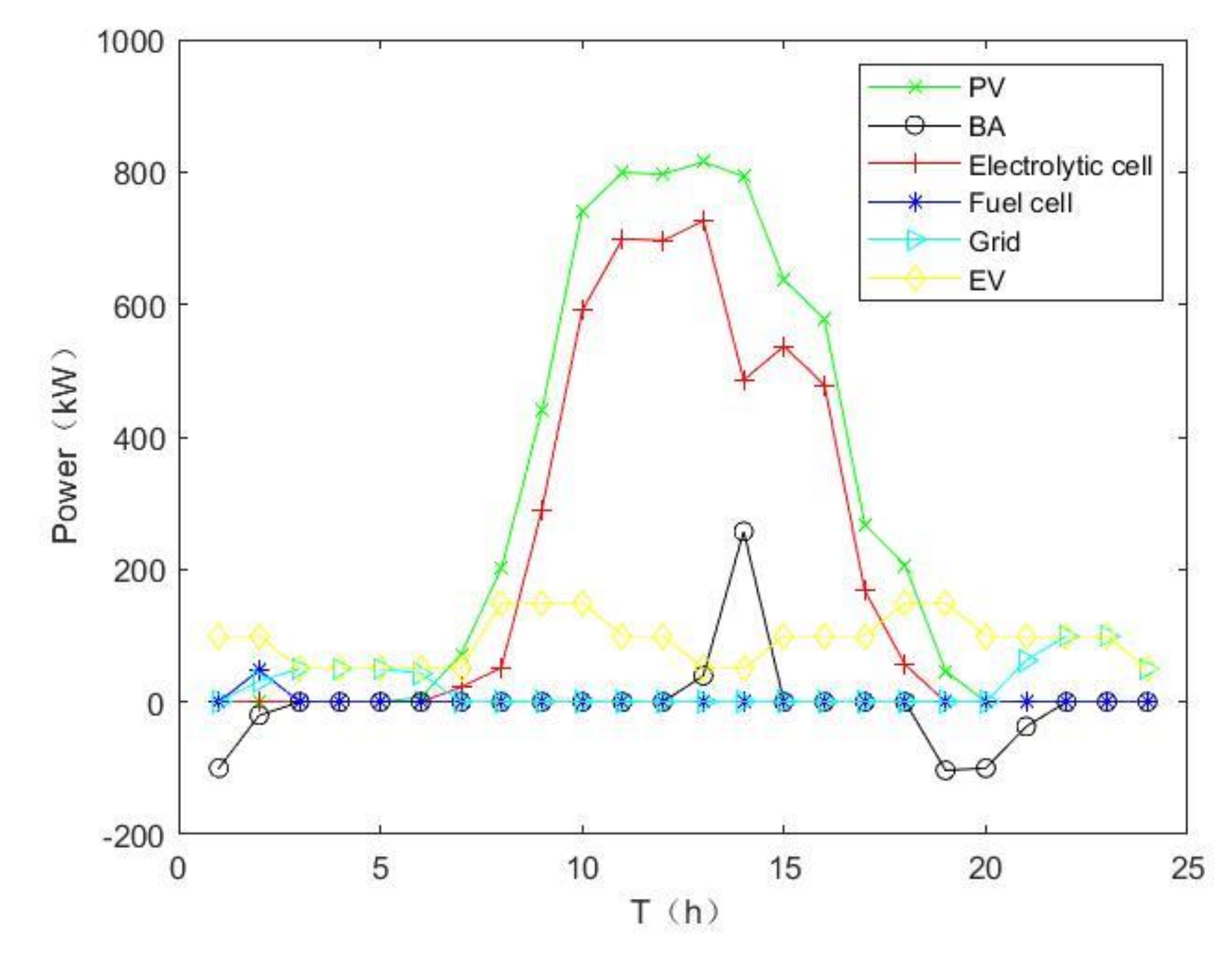
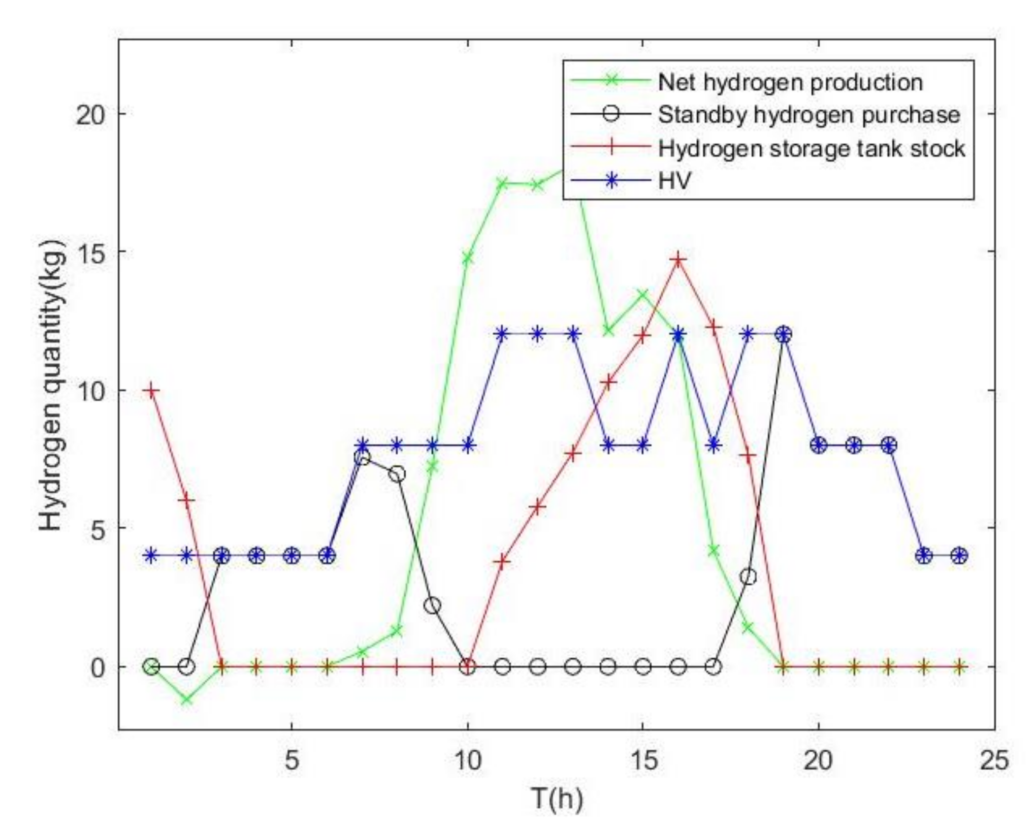
5.3. Operation Analysis of Integrated Charging Station

The optimized configuration results select a certain day to analyze each component’s electric power balance and hydrogen balance in the total charging station and the charging and discharging trend of battery energy storage and hydrogen energy storage. See the following figures.
From the operation result diagram of each component, it can be concluded that optimized configuration can make the integrated charging station operate effectively. It can be seen from Figure 5 that during periods 1 to 6, electric vehicles are mainly powered by battery energy storage, hydrogen energy storage system, and grid supplementary power supply. From 7 to 19, the light is sufficient. On the premise of meeting the demand for electric vehicles, the photovoltaic output provides power storage and hydrogen production from electrolytic water. From 18 to 24 h, electric vehicles are mainly powered by batteries and power grids. It can be seen from Figure 6 that in the early morning and at night, the demand for hydrogen fuel vehicles is mainly provided by the residual hydrogen in the hydrogen storage tank and the purchased standby hydrogen. During the daytime, the photovoltaic output produces hydrogen by electrolysis. After removing the hydrogen consumed by the fuel cell, the net hydrogen can meet the demand, and the remaining hydrogen in the hydrogen storage tank can provide the demand for the night. Figure 7 and Figure 8 show the working state of the storage battery and hydrogen storage tank in one day.

6. Conclusions

This paper proposes to establish a comprehensive charging station for photohydrogen storage based on the charging station. It can serve electric vehicles and hydrogen fuel vehicles simultaneously and has a specific independent energy supply capacity. Firstly, this paper introduces the structure and operation mode of the integrated charging station, models the components to be configured in the station, and designs four energy flow strategies to operate the integrated charging station effectively. Taking the minimum annual investment and operation cost and the minimum proportion of energy purchase as the objective function, the optimal allocation model is established and solved by the NSGA-II algorithm. For the Pareto optimal solution, the optimal compromise scheme of a fuzzy comprehensive evaluation is adopted. The effectiveness of the optimization results is proved by analyzing the operation of components in the station. As the two types of vehicle demand considered are given parameters, the participation and response of customers guided by electricity price can be further considered to improve the local consumption of photovoltaic and reduce the amount of grid access.

Author Contributions

Conceptualization, M.W.; methodology, M.W.; software, X.D.; validation, X.D.; formal analysis, X.D.; resources, M.W.; data curation, Y.Z.; writing—original draft preparation, X.D.; writing—review and editing, X.D.; visualization, X.D.; supervision, M.W. All authors have read and agreed to the published version of the manuscript.

Funding

This research received no external funding.

Institutional Review Board Statement

Not applicable.

Informed Consent Statement

Not applicable.

Data Availability Statement

Not applicable.

Conflicts of Interest

The authors declare no conflict of interest.

Nomenclature

CRFCapital recovery factor
C 1 Investment cost
C 2 Maintenance cost
C 3 Running cost
C 4 Sale of electricity revenue
EVElectric vehicle
e p v Unit price of photovoltaic
e b a Unit price of battery
e w e Unit price of electrolytic cell
e f c Unit price of fuel cell
e H Unit price of hydrogen tank
e G i Unit price of electricity
e H i Unit price of hydrogen
e G o Unit price of selling electricity
E B Capacity of battery
F 1 Operating cost
F 2 Purchase electricity proportional to demand
F 3 Purchase hydrogen proportional to demand
F n m Function value of the m non-inferior solution of the n objective function
G T Sunlight intensity
G S T C Rated sunlight intensity
H Hydrogen content of the hydrogen storage tank
HVHydrogen vehicle
H w e Electrolytic cell manufacturing hydrogen
H f c Fuel battery consumption hydrogen gas
H l Hydrogen vehicle demand
H G Consumption of spare hydrogen
HHVRatio conversion of hydrogen and electricity
K Maintenance factor
PVPhotovoltaic
P p v Photovoltaic power generation
P p v S T C Photovoltaic rated power
P b a Battery charge and discharge power
P w e Electrolytic cell consumption power
P f c Fuel cell power supply
P l Electric vehicle demand
P G Grid power
P G i Grid power supply
P G o Power on grid
r Annual interest rate
SOCState of charge
T C Temperature
T S T C Rated temperature
y Active life
η Efficiency of battery
η w e Efficiency of electrolytic cell
η f c Efficiency of fuel cell
μ n m Membership of the m non-inferior solution of the n objective function

References

  1. Zeng, M.; Wang, Y.; Zhang, S.; Liu, Y. 12 key issues in the energy planning of the 14th five-year plan and the realization of the “30.60” double carbon goal. China Power Enterp. Manag. 2021, 1, 41–43. [Google Scholar]
  2. Li, W. Analysis of energy status and some important strategic countermeasures. Chem. Enterp. Manag. 2021, 10, 13–14. [Google Scholar]
  3. Pan, Q.; Hao, L. The impact of the new round of oil crisis on China’s National Defense Supply and countermeasures. Def. Ind. Convers. China 2020, 6, 39–40. [Google Scholar]
  4. Fang, G.; Wang, Q. Exploration on the path of energy low-carbon transformation under the guidance of double carbon goal. Coal Econ. Res. 2021, 41, 4–12. [Google Scholar]
  5. Hosseini, S.E.; Wahid, M.A. Hydrogen production from renewable and sustainable energy resources: Promising green energy carrier for clean development. Renew Sustain. Energy Rev. 2016, 57, 850–866. [Google Scholar] [CrossRef]
  6. Jahangiri, M.; Soulouknga, M.H.; Bardei, F.K.; Shamsabadi, A.A.; Akinlabi, E.T.; Sichilalu, S.M.; Mostafaeipour, A. Techno-econo-environmental optimal operation of grid-wind-solar electricity generation with hydrogen storage system for domestic scale, case study in Chad. Int. J. Hydrog. Energy 2019, 44, 28613–28628. [Google Scholar] [CrossRef]
  7. Hannan, M.A.; Lipu, M.S.H.; Ker, P.J.; Begum, R.A.; Agelidis, V.G.; Blaabjerg, F. Power electronics contribution to renewable energy conversion addressing emission reduction: Applications, issues, and recommendations. Appl. Energy 2019, 251, 113404. [Google Scholar] [CrossRef]
  8. Su, S.; Jiang, X.; Wang, W.; Jiang, J.; Geng, J. Microgrid energy optimization management considering electric vehicles and photovoltaic energy storage. Autom. Electr. Power Syst. 2015, 39, 164–171. [Google Scholar]
  9. Lu, X.; Liu, L.; Chen, Z.; Zhang, J.; Xiao, X. Multi objective optimal scheduling method for electric vehicle photovoltaic charging station. Trans. China Electrotechical Soc. 2014, 29, 46–56. [Google Scholar]
  10. Liu, S.; Zhang, H. Development status and Enlightenment of foreign electric vehicle industry. China Natl. Cond. Strength 2020, 10, 63–66. [Google Scholar]
  11. Chen, Z.; Xiao, X.; Lu, X.; Liu, N.; Zhang, J. Multi objective capacity optimization allocation method for electric vehicle charging station with photovoltaic power generation system. Trans. China Electrotechical Soc. 2013, 28, 238–248. [Google Scholar]
  12. Zhang, Y.; Liu, N.; Zhang, J.; Li, Y. Optimal capacity allocation of wind solar complementary system with electric vehicle charging station. Power Syst. Prot. Control 2013, 41, 126–134. [Google Scholar]
  13. Lu, J.; Yang, Y.; Wang, Y.; He, T. Energy storage configuration of electric vehicle photovoltaic charging station based on Copula theory. Acta Energ. Sol. Sin. 2016, 37, 780–786. [Google Scholar]
  14. Sun, Y.; Liu, J.; Liu, H.; Zhang, K.; Chu, Z.; Liu, J. Capacity configuration of centralized charging station considering recycling of rechargeable battery pack. Electr. Meas. Instrum. 2016, 53, 80–86. [Google Scholar]
  15. Li, W.; Tong, Y.; Zhang, W. Energy storage capacity allocation method of electric vehicle charging station considering battery service life. Adv. Technol. Electr. Eng. Energy 2019, 39, 55–63. [Google Scholar]
  16. Li, J.; Shi, Y.; Zhang, L.; Yang, X.; Wang, L.; Chen, X. Energy storage capacity optimization strategy of optical storage and charging station considering orderly charging of electric vehicles. Power Syst. Prot. Control 2021, 49, 94–102. [Google Scholar]
  17. Li, Q.; Zhao, S.; Pu, Y.; Chen, W.; Yu, J. Capacity allocation optimization of hybrid energy storage microgrid considering electric hydrogen coupling. Trans. China Electrotechical Soc. 2021, 36, 486–495. [Google Scholar]
  18. Liu, N. Research on Multi-Objective Optimization Algorithm and Application Based on Evolutionary Algorithm. Master’s Thesis, Nanjing University of Aeronautics and Astronautics, Nanjing, China, 2010. [Google Scholar]
  19. Zhang, T.; Wang, C.; Wang, L.; Zhang, D.; Zhang, J. Double level optimal dispatching model of power selling companies considering the participation of virtual power plants. Power Syst. Technol. 2019, 43, 952–961. [Google Scholar]
  20. Tong, S.J.; Same, A.; Kootstra, M.A.; Park, J.W. Off-grid photovoltaic vehicle charge using second life lithium batteries: An experimental and numerical investigation. Appl. Energy 2013, 104, 740–750. [Google Scholar] [CrossRef]
  21. Liu, G.; Yu, H.; Kang, K.; Zhang, J. Capacity allocation of optical storage and charging station considering demand response and carbon emission. Proc. CSU-EPSA 2021, 33, 106–112. [Google Scholar]
  22. Xiong, Y.; Si, Y.; Zheng, T.; Chen, L.; Mei, S. Optimal allocation of hydrogen energy storage in integrated energy system of Industrial Park Based on master-slave game. Trans. China Electrotechical Soc. 2021, 36, 507–516. [Google Scholar]
Figure 1. Structure diagram of the integrated charging station.
Energies 14 07087 g001
Figure 2. Energy flow strategy of the integrated charging station.
Energies 14 07087 g002
Figure 3. Optimization flow diagram.
Energies 14 07087 g003
Figure 4. Pareto solution set.
Energies 14 07087 g004
Figure 5. Electric power balance.
Energies 14 07087 g005
Figure 6. Hydrogen balance.
Energies 14 07087 g006
Figure 7. Battery state of charge.
Energies 14 07087 g007
Figure 8. Hydrogen state of the hydrogen tank.
Energies 14 07087 g008
Table 1. Component parameters.
ComponentPower Price (yuan/kW)Service Life (year)
Photovoltaic700020
Battery12005
Electrolytic cell14,00010
Fuel cell14,00010
Hydrogen tank338010
Table 2. Optimization results.
Optimization ObjectiveOptimization Result
Photovoltaic (kW)100
Battery (kW)362
Electrolytic cell (kW)734
Fuel cell (kW)136
Hydrogen tank (kg)64
Annualized cost (yuan)3,620,953.085
The proportion of power purchase (%)0.305
The proportion of standby hydrogen purchase (%)0.481
Publisher’s Note: MDPI stays neutral with regard to jurisdictional claims in published maps and institutional affiliations.

