1. Introduction
The basis for reliable simulation calculations of synchronous generators, operating alone or in the power system, is the determination of appropriate models and reliable parameters of these generators. A set of parameters of these models includes the leakage reactance, whose one component is the leakage reactance of end windings Xe. The paper addresses the problem of determining the value of this reactance for high-power generators. A description of the method and the results of calculations of this reactance using the finite element method (FEM) under the assumption of a three-dimensional field model of a synchronous generator are presented in the paper.
The issues related to the description of electromagnetic phenomena occurring in the end region of synchronous generators are among the more difficult problems in the theory of electrical machines. The reasons for these difficulties include, i.e., complex geometric shapes of end windings and other structural elements in this region, as well as the complexity of electromagnetic phenomena.
The electric current flowing through the end windings of the stator winding produces a magnetic flux in the machine end region, which generally has a three-dimensional distribution (3D). The leakage reactance of the end windings of the synchronous machine is associated with this flux.
In order to make the calculations carried out with the use of two-dimensional field-circuit models more accurate, these models are supplemented with resistances and inductances of the end windings of the stator winding in the form of lumped parameters. This approach is commonly known and most often used in practice [
1,
2,
3]. In traditional investigations, the values of these parameters are estimated based on the design data, when using approximate analytical relationships known from the design studies [
4,
5,
6,
7].
The leakage reactance of the stator end windings can also be determined indirectly by measuring the reactance of the stator winding with the rotor removed, supplied with a reduced, symmetrical three-phase voltage with a rated frequency. In this case, the stator winding reactance is the sum of the resultant leakage reactance and the stator bore reactance [
5,
8]. The bore reactance can be calculated on the basis of the design data or determined by measurement using an auxiliary coil placed in the inner cylinder of the machine with a span of one pole pitch and a length equal to the active part of the stator laminations. The difference between the stator reactance and the bore reactance is the total leakage reactance of the stator winding [
8]. From the stator leakage reactance, it is possible to extract the reactance of the end windings by installing an additional measuring coil in the area of the end region whose active sides adjoin the bars of the stator end windings [
9,
10].
Due to the complicated shape of the end windings, the use of such a measurement method is difficult to carry out and involves high costs, especially in the case of high-power machines. For these reasons, different calculation methods are usually used to determine the leakage reactance of the stator end windings. The paper presents the results of calculations of the generator stator leakage reactance obtained with the use of FEM and those obtained from approximate, analytical design relationships. The analysis of the electromagnetic field was performed using the Ansys Maxwell 3D program for a 200 MW cylindrical synchronous generator.
2. Determination of the Stator Leakage Reactance Based on Analytical Relationships
The end region of high-power synchronous machines, in which the end windings of the stator windings are located, is an area with a very complex structure. The end windings, inclined at some angle to the shaft axis, create a conical surface. The density of the current flowing through the end windings can be divided into three components: radial, circumferential and axial. As a consequence, the distribution of the magnetic field in the end region is three-dimensional. The distribution of the magnetic field is influenced by the spatial arrangement of the end windings as well as the presence of a ferromagnetic core, a magnetic shield, a pressure plate and a housing. The above-mentioned factors make the analysis of the phenomena taking place in this region very difficult.
Due to the complicated geometrical structure of the end region, it is difficult to calculate the magnetic field distribution and the leakage reactance of the stator end windings. Necessarily, many simplifying assumptions that lead to approximate relationships are made in the analytical calculations. One of the assumptions, used in the previous works, is the omission of the radial component of the current in the end windings, which corresponds to the replacement of the conical surface of the end windings with a cylindrical one. In consequence of this assumption, the analysis of a three-dimensional magnetic field distribution is brought to the analysis of a two-dimensional magnetic field distribution. Due to the long sections of air that occur along the path of the magnetic flux in the region of the end windings, it is assumed that the value of the leakage reactance of the end windings does not depend on the saturation of the magnetic circuit. Under this assumption, the reactance can be expressed as the sum of the circumferential and axial reactances. In the approximate analysis, the effect of currents induced in copper or aluminum screens is neglected.
The final formulas for the reactance Xe are usually functions of the respective leakage permeances of the end windings λe. Various analytical relationships can be found in the scientific and technical literature, including:
Equation according to Abramow [
6]:
Equation according to Dąbrowski [
4]:
Equation according to Richter [
5]:
Equation according to Cioc and Nica [
7]:
The symbols used in Equations (1)–(6) denote:
N1—the number of turns of the stator winding;
kw1—stator winding factor for the first harmonic of the magnetomotive force;
le1—length of one half of the end connection length on the one side of the stator core;
UN, IN, SN—rated stator voltage and current and the rated apparent power of the synchronous machine;
μ0—magnetic permeability of the vacuum;
p—the number of pole pairs;
q—the number of slots per pole and phase;
D1—stator core inner diameter;
β—relative pitch (coil span) of the stator winding;
D, F—coefficients depending on the type of winding; their values were selected experimentally;
τ—pole pitch.
The calculations of the reactance of the end windings, presented in this paper, were carried out for a TWW-200-2A high-power synchronous generator with rated data: S
N = 235.5 MV · A, P
N = 200 MW, U
N = 15.75 kV, I
N = 8625 A,
nN = 3000 rpm. Based on the design data of the end windings of the stator winding, presented in
Table 1, the value of reactance
Xe was calculated using Equations (1)–(6). The calculation results expressed in relative units are given in
Table 2.
The reactance calculated according to the formulas proposed by different authors varies over a relatively wide range of p.u. In order to more precisely determine the leakage reactance of synchronous generator stator end windings, it is justified to use modern computational methods, e.g., the finite element method.
3. Determination of the Leakage Reactance of the End Windings of the Stator Winding Using the Finite Element Method
The mathematical description of the physical phenomena occurring in an electric machine is possible with the use of field or field-circuit models in which Maxwell’s equations are adapted to the respective types of machines. The reliability and, consequently, the usefulness of the results of such calculations largely depend on the accuracy of determination of the electromagnetic field inside the machine. The traditionally used, often simplified, methods for calculations of electromagnetic fields, based on analytical relationships, are increasingly being replaced by modern numerical methods. Nowadays, the finite element method is one of the more and more frequently used numerical methods dedicated to the computation of electromagnetic field distributions [
11,
12,
13]. Thanks to this method, it is possible to correctly formulate the mathematical model of a synchronous machine and to design its electromagnetic circuit without the need to build expensive prototypes [
14,
15,
16,
17]. The field and field-circuit models for calculating electromagnetic quantities in electrical machines, based on the finite element method, currently provide the most accurate results. In these models, it is possible to take into account essential electromagnetic phenomena and factors determining the properties of the machine, such as: the nonlinearity of the magnetization characteristics of magnetic cores, the effect of eddy currents in conductive constructional elements, and the influence of higher harmonics of the magnetic field [
16]. The accuracy of the calculations using FEM models is largely determined by the reliability of material and construction data of the analyzed machine.
The basis for determining the leakage reactance of the end windings is the analysis of the electromagnetic field in the end region. The use of FEM allows taking into account the actual shapes of all constructional elements and the actual properties of the materials from which they are made, including materials with nonlinear magnetization characteristics and with anisotropic magnetic and electrical properties.
The FEM models used in the calculations of electromagnetic fields in the region of the end windings of generators can be divided into:
The so-called 2.5-dimensional (quasi-3D) models are period models in which the geometric structure of the end region is axisymmetric and the field distribution in the direction of the circumferential coordinate is periodic. The analysis of the electromagnetic field is performed in the plane of the cross-section of the generator end winding region passing through the axis of the machine shaft, when assuming that the distribution of the electromagnetic field in the circumferential direction is sinusoidal [
18,
19]. The radial and axial components of the current densities in the end windings are neglected. In the region of the end windings, an equivalent current is forced in the circumferential direction, representing the magnetomotive force of the three-phase winding. Most commercial programs for the field calculations by the finite element method do not allow the creation of 2.5D models.
However, the complex geometric structure of the generator end region requires the use of three-dimensional (3D) field models. Calculations of electromagnetic field distributions based on 3D models, both in transient and steady states, are very time-consuming and require computers with high-computing power. On the other hand, these models allow obtaining the most accurate calculation results [
20,
21,
22,
23,
24,
25].
To reduce the size of the systems of equations to be solved and to speed up the calculations, simplifications of field models are often applied. They consist in using the geometric and magnetic symmetry of the machine and considering only one symmetrical part, e.g., including one pole pitch of the machine circuit.
In the paper, the method of determining the leakage reactance of the end windings of the stator winding based on a three-dimensional model of a TWW-200-2A synchronous generator is presented.
3.1. Equations of the Electromagnetic Field
When formulating boundary problems in three-dimensional areas in the finite element method, one usually does not describe the field by means of the vector magnetic potential
A, since it does not make the solution of the field equations easier. Potential
A is most often used in the analysis of electromagnetic fields in two-dimensional areas. In the calculations of three-dimensional electromagnetic fields by the finite element method, the so-called
T-
Ω formulation is employed [
26,
27]. It uses the electric vector potential
T and the scalar magnetic potential
Ω. In this approach, the size of the system of FEM equations to be solved is significantly reduced compared to the description of the field using the vector magnetic potential
A.
The starting point for the
T-
Ω formulation are Maxwell’s equations describing the quasi-stationary electromagnetic field:
where:
B,
H,
D,
E—vectors of magnetic flux density and intensity of the magnetic and electric fields.
Acting the divergence operator on both sides of Equation (7), one obtains the condition for non-divergent field of the current density vector
J:
The current density vector
J can be represented as the curl of the vector
T, called the vector electric potential:
Substituting (12) into Equation (7) one obtains:
Since the gradient curl of any scalar quantity is zero, an irrotational vector
can be presented in the form:
Potentials
T and
Ω are not defined uniquely because another pair of potentials:
where φ is any scalar function, also satisfies Equations (12) and (14).
The field equations for the potentials
T and
Ω result from Equations (8) and (9). Taking into account the equation
J =
γE and relationships (12) and (14) one obtains:
where:
γ,
μ—electric conductivity, magnetic permeability.
In non-conductive regions, Equation (18) reduces to the form:
Equations (17)–(19) do not have an unambiguous solution due to the ambiguity of the potentials. Assumption of the Coulomb gauge [
28]
leads to the equations:
The use of the Lorentz gauge [
28] of the form:
causes decoupling of equations with respect to the unknowns
T and
Ω, as a result of which one obtains:
For a sinusoidal time-varying (monoharmonic) electromagnetic field, the field analysis is usually performed in the frequency domain. The vectors of sinusoidal variables are then represented by complex phasor-vectors, and the time derivatives correspond to the complex frequencies, . The above equations are implemented in Ansys Maxwell 3D.
3.2. Three-Dimensional Field Model of a Synchronous Generator and the Calculation Results of the Leakage Reactance of the Stator End Windings
The assumption of a three-dimensional (3D) model of a synchronous generator for analysis makes it possible to take into account the finite length of ferromagnetic cores and the leakage fluxes of end windings. The 3D model of the synchronous generator was developed for calculations of the leakage reactance of the stator end windings.
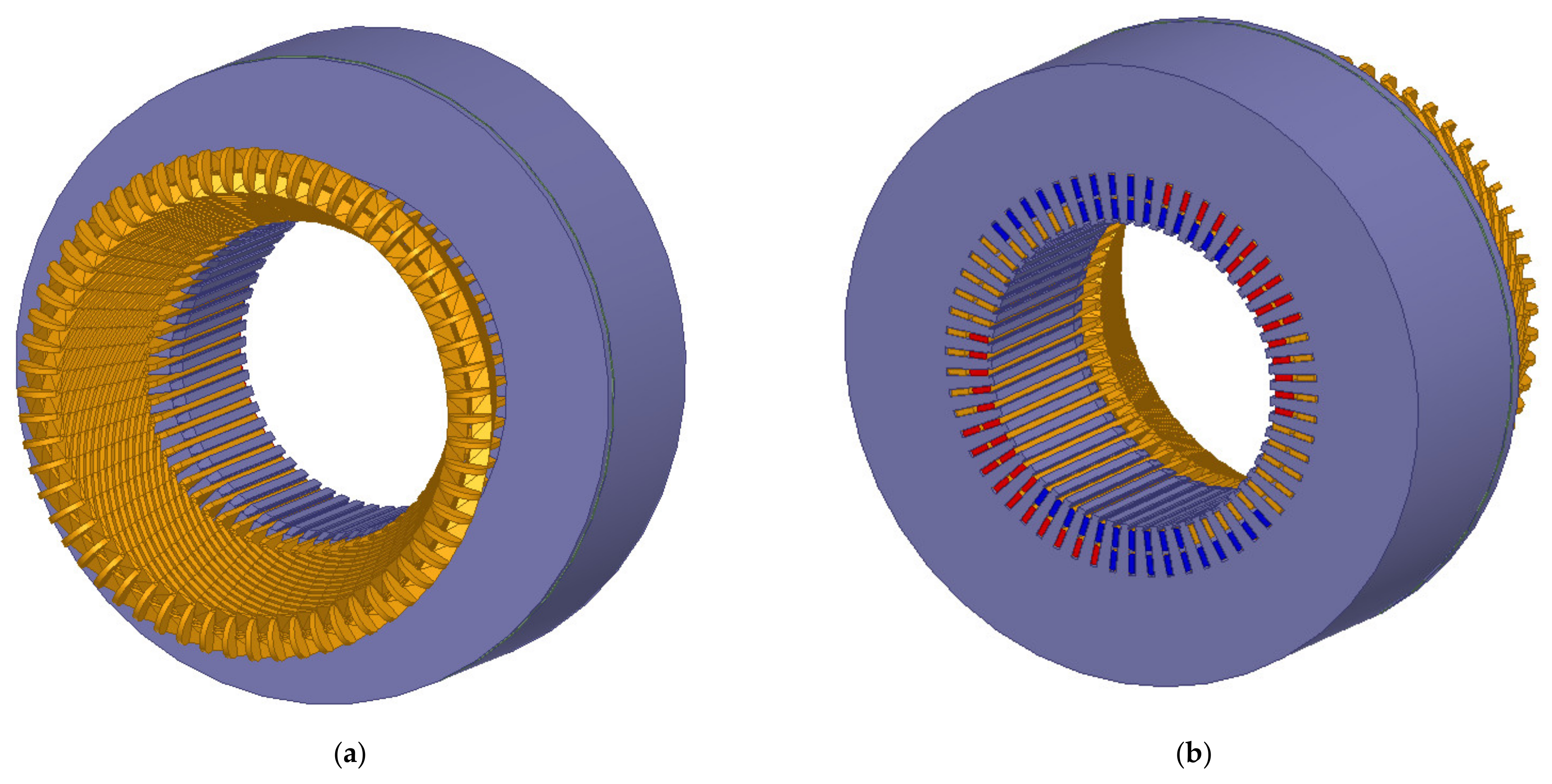
Figure 1a,b shows the computational model of a synchronous generator. Taking into account the symmetry of the magnetic field distribution with respect to the plane perpendicular to the longitudinal axis of the machine and passing through its center, the area covering half the length of the machine can be analyzed. A further reduction of the computational model was obtained by shortening by half the axial length of the active part of the core laminations. It can be assumed with a good approximation that in the part of the core not included in the model, the distribution of the magnetic field is two-dimensional, i.e., the axial component of the magnetic flux density is close to zero (
Bz ≈ 0). So, the computational model contained a quarter of the active part of the machine core. This allowed a reduction in the size of the problem being solved while reducing the computation time.
Figure 2 presents a fragment of the finite element mesh. In order to improve readability, the finite element mesh in the air regions of the machine is not shown.
The total number of finite elements was 1.613 million tetrahedra. Further thickening of the mesh was no longer possible due to the limited operating memory resources of the workstation used. It should be added that such a number of finite elements ensured obtaining the calculation results with an acceptable accuracy.
Calculations of the leakage reactance of the stator end windings were carried out for the rotor removed [
9]. The developed 3D model of the generator takes into account the stepped end region of the core [
29], which is characteristic for high power machines. The linear magnetic circuit of the core was assumed for the calculations. The value of the leakage reactance of the end windings is practically constant because the magnetic leakage field lines largely run through the air.
The inhomogeneous area of the ferromagnetic core, which occurs in the actual machine, was replaced in the model by a homogeneous area with anisotropic properties, among others due to the presence of insulation between electrical sheets [
30,
31]. The magnetic permeabilities of the core in the radial, circumferential and axial directions were assumed to be constant. They satisfy the relations
μr =
μϕ >
μz.
In addition, the currents induced in the annular copper shield mounted on the outer part of the stator laminations were taken into account. The machine frame, not visible in
Figure 1, was modeled as a cylindrical surface surrounding the end region.
On the external surfaces of the generator model, a zero-boundary condition was imposed for the normal component of the magnetic flux density vector B. This condition also applies to the generator circular cross-sectional area that intersects the stator winding bars in the active part. On this surface, it was assumed that the normal component of the magnetic flux density is equal to zero.
In individual phases of the stator winding, sinusoidal currents of the same amplitude and frequency of 50 Hz, shifted to each other by 120° were forced.
Figure 3 shows the distribution of magnetic flux density (in vector form) in the region of the stator end windings of the synchronous generator. It can be seen that due to the nature of the currents in the stator windings, the distribution of the field of magnetic flux density
B, sinusoidal in time, is irregular and complicated.
In
Figure 4, the distribution of the current density
J (in vector form) in the copper ring screen of the synchronous generator is presented. In this figure, one can observe the eddy and uneven nature of the induced currents, the influence of which contributes to the reduction of the axial component of magnetic flux density
Bz, which in turn affects the reactance value of the end windings of the stator winding.
Two methods of determining the reactance of stator end windings can be distinguished [
28]. The first one is based on the energy stored in the magnetic field and the second one on the magnetic flux linkage. Both methods are equivalent to each other in a linear magnetic environment. Due to the efficiency of numerical calculations, the leakage reactance of the end windings (expressed in relative values) was determined by the first method from the equation [
32,
33]:
where:
Im—current amplitude;
m—number of stator phases;
We—average energy for the period stored in the region of the two-stator end windings;
ω—pulsation.
The magnetic field energy accumulated in one area of the end region with the volume
V was calculated from the formula:
where “
” denotes conjugation of a complex quantity, and
We = 2
We1.
The leakage reactance of the stator end windings was calculated from the Equation (25) and equaled Xe = 0.063 p.u.
The value of reactance
Xe calculated with the use of FEM was taken as the reference one and compared with the values obtained from the analytical Equations (1)–(6) (
Table 2).
Table 3 presents the relative errors of the analytical calculations.
It follows from
Table 3 that from among the reactance values calculated on the basis of analytical formulas, the closest value to the reference value is obtained from the Dąbrowski Equation (2). Due to the high complexity of the phenomena and the multitude of design solutions of end windings of synchronous generators, the above conclusion is not of a general nature.
4. Determination of the Leakage Reactance of the End Windings of the Stator Winding Using the Finite Element Method
The operational properties of synchronous machines operating in the power system can be determined on the basis of measurements made on real objects or on the basis of simulation tests. Due to the risk of failure, measurement tests of high-power synchronous machines are usually performed under normal operating conditions, for which the currents flowing in the windings do not exceed the rated values. Simulation investigations are not subject to such limitations. Currently, two-dimensional field-circuit models based on the finite element method are often used for the analysis of the electrodynamic states of synchronous generators. These models allow solving simultaneously: electromagnetic field equations, voltage-current equations of external electric circuits connected to windings and equations of rotor rotation. The consequence of using two-dimensional field-circuit models of synchronous generators is the omission of the inductance of winding end connections resulting from the finite length of the magnetic cores. In order to make the calculation results more accurate, these inductances are taken into account by means of external electrical circuits connected to the modeled windings in the field part. According to the theory of electrical machines, the reactance of end connections can affect significantly the waveforms of electrical and mechanical quantities, in particular, in transient states. For this reason, its influence was assessed by analyzing the waveforms of the synchronous generator for a symmetrical three-phase short-circuit in the stator winding.
The two-dimensional field-circuit model of the generator consists of differential equations with partial derivatives describing the distribution of the electromagnetic field inside the machine and differential equations with ordinary derivatives describing the voltage-current relationships in the electric circuits of the windings. When creating a computational model of a synchronous machine, the following were taken into account:
Nonlinear magnetization characteristics of the stator and rotor magnetic cores;
Eddy currents induced in the solid block and slot wedges;
Constant rotational speed equal to the synchronous one.
In the computational model, the eddy currents induced in the stator laminations and the phenomenon of current displacement in the stator and rotor windings were neglected.
The description of the electromagnetic field inside the machine is based on the vector magnetic potential
A, which in two-dimensional areas has a non-zero component only in the axis of the machine shaft. The equation describing the space-time distribution of the electromagnetic field in the low frequency range has the following general form:
where:
Je—the vector of the current density of external sources;
V—scalar electric potential;
v—the vector of the speed of the area moving relative to the electromagnetic field;
ν(B), γ—magnetic reluctance, electrical conductivity.
Introduction of the potentials instead of the vectors of magnetic flux density B and intensity of magnetic field H to the description of the two-dimensional distribution of the electromagnetic field results in reducing the number of variables.
The Kirchhoff equations describing the electromagnetic state of the
j-th winding are of the form:
where:
Rj—resistance of the j-th winding;
ψj, ij, uj—instantaneous values of the flux linkage, current and voltage of the j-th winding;
l—the effective length of the machine.
Due to the complex geometric structure of the machine and nonlinear properties of magnetic materials, the analytical solution for the above equations is impossible. In such cases, the problem can conveniently be solved by means of numerical methods, e.g., using the finite element method.
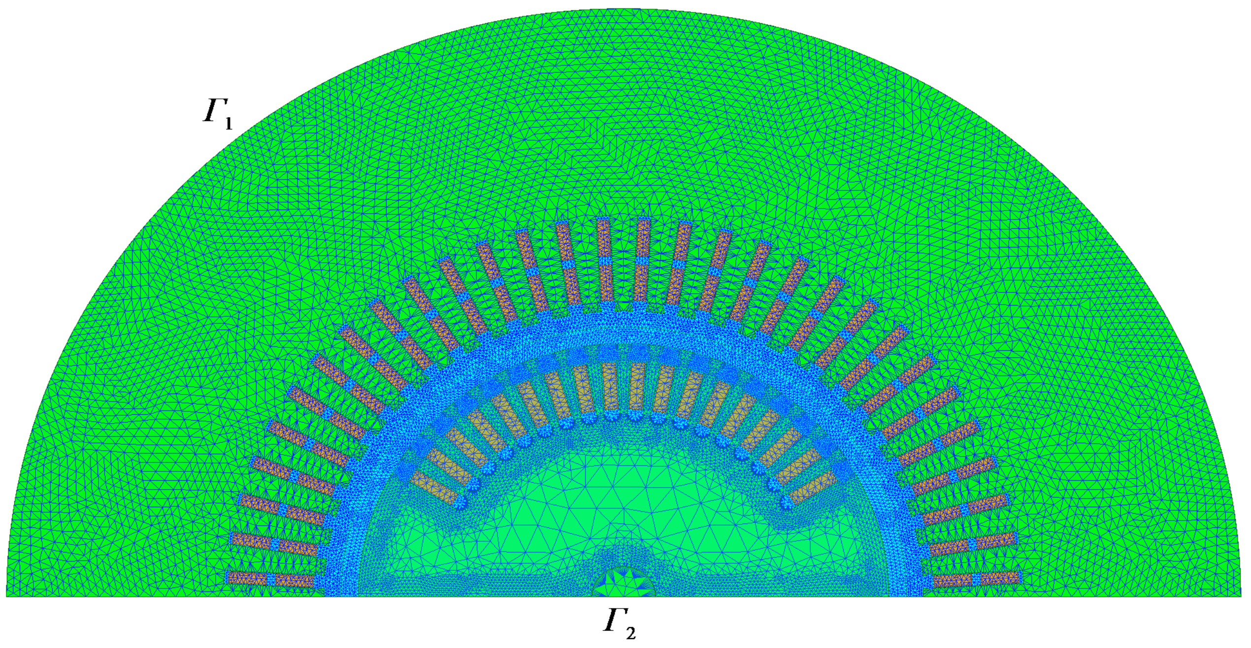
A two-dimensional field-circuit model of the synchronous machine was developed in Ansys-Maxwell 2D environment. This program allows calculating distributions of electromagnetic fields in a two-dimensional space using the finite element method. Due to the magnetic circuit symmetry, the area of the half of the machine cross-section was assumed for the calculations when taking into account the homogeneous Dirichlet boundary condition on the outer edge
Γ1 and the symmetry condition on the edge resulting from cutting the machine cross-section
Γ2.
Figure 5 shows the two-dimensional model of the analyzed synchronous generator together with a grid of triangular elements consisting of 48,240 elements. This model was verified experimentally based on the comparison of the measured and calculated no-load and three-phase short-circuit characteristics [
2].
The analysis of the impact of the inductance of end windings was carried out by calculating the waveforms in the initial moments of the three-phase short-circuit of the stator windings of the synchronous generator. Each time it was assumed that before the short-circuit occurrence, the generator operated at no-load and was excited approximately to the half of the rated voltage. The state of the three-phase short-circuit was initiated when the voltage in the stator phase A was equal to zero. In order to increase readability, the impact of the inductance of the end windings on the waveforms is presented for the extreme inductance values given in
Table 2 (i.e., the inductance determined acc. to Cioc, Nico and Abramov) and for the inductance calculated with use of the 3D model.
Figure 6 shows a comparison of the calculation results of the waveforms of the phase currents of stator windings
iA,
iB,
iC, and the field current
if at the three-phase short-circuit for various inductance values of the end windings. The waveforms of currents are given in relative values. As a reference quantity, the current
was assumed for the stator currents and the current
Ifbase for the field current, to which the rated voltage on the stator terminals at no-load corresponds.
Assuming the calculation results obtained for the inductance of the end windings determined, with use of the 3D model as reference quantities, it can be stated that the largest differences between the analyzed waveforms of the stator currents are observed in the initial transient state. If the inductance determined acc. to the Abramov formula is used for calculations, the highest deviations in the stator currents are approx. 10% and in the case of using the inductance acc. to the Cioc and Nioa formula they are approx. 8%. The deviations in the field current are smaller and equal to approx. 4% and 6%, respectively.
Figure 7 shows the distributions of the magnetic flux density amplitude in the form of a color map in the entire cross-section. These distributions are presented for the moment for which the current in the stator winding
iA reaches the maximum value, that is for
t = 0.01 s. For such a selected time instant, the values of the magnetic flux density are highest.
From the analysis of the magnetic flux density distributions, it follows that the largest values are in the area of the stator teeth and in the near-surface area of the rotor. In addition, with the increase in the inductance of the end windings, the value of the magnetic field density in the machine decreases.
From the above analysis of the calculation results, it can be seen that the value of the inductance of the end windings affects the waveforms of electrical and magnetic quantities. This influence can in particular be observed in the transient state and may lead to erroneous conclusions being the basis, e.g., the assessment of operational properties of machines, selection of protections or settings of control systems. The use of 3D models of synchronous generators, among others, for calculating distributions of variables in time fields, is still very limited due to high hardware requirements and a time-consuming process of obtaining results. Therefore, a reasonable solution seems to use 3D models to determine the inductance of end windings and to include it in electric circuits of external two-dimensional field-circuit models.
5. Summary and Conclusions
This paper addresses the following important problem: computing parameters of synchronous generator models. The calculation methods for the leakage reactance of end windings, which is one of the components of the stator leakage reactance of synchronous generators, are presented. The paper focuses on the determination of the reactance of the end windings of a high-power synchronous generator based on the analysis of the electromagnetic field distribution in the end region, calculated with the use of FEM. For this purpose, a 3D computational model of the synchronous generator was developed. The effect of eddy currents induced in the conductive screen which disturb the electromagnetic field distribution in the region of the end windings was taken into account in this model.
The following conclusions can be drawn from the presented analyzes and calculations:
It is possible to determine the reactance of the end windings with a good accuracy based on the analysis of the three-dimensional distribution of the electromagnetic field in the generator end region, calculated with the use of FEM. Mathematical three-dimensional models compared to two-dimensional ones allow obtaining more accurate calculation results due to a smaller number of simplifying assumptions taken for analysis.
Due to the lack of available results of measurements made on a real object, the reactance determined with the use of the 3D generator model, calculated by FEM, was assumed as the reference value. It can be concluded that the so-calculated reactance value of the end windings differs significantly from the values obtained from the approximate design formulas (
Table 3). This is due to the fact that the analytical relationships found in the literature used to calculate the leakage reactance of the stator end windings, are simplified and do not take into account, i.e., the effect of the currents induced in conductive screens.
The development of the calculation model and single 3D calculations of the electromagnetic field distribution are time-consuming. However, it is possible to conveniently change the structure and material constants in the developed model. Consequently, based on the prepared model, one can perform multi-variant and detailed investigations and draw reliable conclusions regarding the operation and construction of synchronous generators.
The calculation results obtained on the basis of the two-dimensional field-circuit model show that the reactance value of the stator end windings has a significant impact on the waveforms of electrical and magnetic quantities. Comparing the results of calculations at the three-phase short-circuit for larger (acc. to the Abramov formula) and smaller (acc. to the Cioc and Nico formula) value of this reactance, the maximum differences in the stator current waveforms of approximately ΔiA ≈ 1 p.u. (ΔiA ≈ 12.2 kA) were obtained. The reactance value of the end windings determined on the basis of different design dependencies (derived under many simplifying assumptions) may contribute to drawing erroneous conclusions from the calculations.


