Abstract
Aside from the industry-standard Gaussian intensity profile, top hat and non-conventional laser beam shapes, such as doughnut-shaped profile, are ever more required. The top hat laser beam profile is well-known for uniformly irradiating the target material, significantly reducing the heat-affected zones, typical of Gaussian laser irradiation, whereas the doughnut-shaped laser beam has attracted much interest for its use in trapping particles at the nanoscale and improving mechanical performance during laser-based 3D metal printing. Solar-pumped lasers can be a cost-effective and more sustainable alternative to accomplish these useful laser beam distributions. The sunlight was collected and concentrated by six primary Fresnel lenses, six folding mirror collectors, further compressed with six secondary fused silica concentrators, and symmetrically distributed by six twisted light guides around a 5.5 mm diameter, 35 mm length Nd:YAG rod inside a cylindrical cavity. A top hat laser beam profile (Mx2 = 1.25, My2 = 1.00) was computed through both ZEMAX® and LASCAD® analysis, with 9.4 W/m2 TEM00 mode laser power collection and 0.99% solar-to-TEM00 mode power conversion efficiencies. By using a 5.8 mm laser rod diameter, a doughnut-shaped solar laser beam profile (Mx2 = 1.90, My2 = 1.00) was observed. The 9.8 W/m2 TEM00 mode laser power collection and 1.03% solar-to-TEM00 mode power conversion efficiencies were also attained, corresponding to an increase of 2.2 and 1.9 times, respectively, compared to the state-of-the-art experimental records. As far as we know, the first numerical simulation of doughnut-shaped and top hat solar laser beam profiles is reported here, significantly contributing to the understanding of the formation of such beam profiles.
1. Introduction
The direct conversion of sunlight into narrow-band coherent laser radiation represents a cost-effective innovation in laser technology via renewable energy. Compared to indirect solar-to-laser conversion by using solar panels, direct solar-to-laser conversion eliminates the intermediate conversion process from solar to electricity and thus may be inherently more efficient, much simpler, and more reliable [1]. Since most of the electronics are no longer required in direct solar-to-laser conversion, potentially limiting problems, for example, related to high voltages [2], can be eliminated. Solar lasers can hence be intently more cost-effective than classical electricity-powered lasers. The dismissal of electrical pumping sources, such as arc lamps and laser diodes, along with their mandatory power consumption and conditioning equipment, constitutes an added value. This makes solar lasers potentially well suited for space-based applications, including deep-space optical communications [3], solar power transmission [4], laser propulsion [5], and asteroid deflection [6]. Additionally, they can be a valuable asset for industries that depend on materials processing at high temperatures [7,8,9].
The efficient extraction of TEM00 mode solar laser power is of utmost importance for many laser-based applications. Its Gaussian laser beam profile can be focused into a diffraction-limited spot with the highest energy density and the lowest beam divergence [10]. Therefore, it is widely applied in the materials processing industry [11]. The irradiance cross-section of Gaussian beams, however, gradually decreases from the center to the periphery of the laser spot so that a portion of the laser beam profile may not have enough irradiance for the given application. Moreover, this wasted energy can even damage surrounding areas outside of the target, extending the heat-affected zones [12]. The simplest way to address this issue is to convert the Gaussian energy distribution into a more uniform profile, such as the top hat beam profile [13]. For this reason, several beam shaping techniques are now on the market: reflective [14] and refractive [15,16,17] configurations, diffractive interference-based models [18,19,20], that can be implemented through digital micromirrors [21] or spatial light modulators [22], intra-cavity modulation [23,24], beam integrators [25] by using Powell [26] or even freeform lenses [27], and via optical fibers with a modified core [28].
Ideally, a top hat beam profile has zero energy at its edges and a constant energy distribution through its cross-section. Experimentally, it is not possible to obtain such an idyllic top hat beam since it would require an infinite spatial frequency spectrum [13], but several approximations can be made, namely Fermi-Dirac, super-Lorentzian, super-Gaussian, flattened Gaussian beams, and multi-Gaussian beams [29,30]. Compared to Gaussian beams, a more flattened beam profile can generate cleaner cuts and sharper edges, resulting in increased accuracy for high-demand applications [31], including laser micro-machining [12], precise materials processing [32], direct laser interference patterning [33] and precise laser surgery [34]. However, generating a top hat profile raises the system cost and complexity while its output power is significantly reduced. Moreover, top hat beam profiles do not preserve their flattened intensity during propagation through an optical system, wilting into the well-known “Airy disk” distribution [13].
Aside from the typical Gaussian intensity profile and the highly accurate top hat profile, non-conventional laser beam shapes are ever more required for specific applications [35]. Annular beams, in particular the doughnut-shaped profile (TEM01* mode), may broaden the laser technology applications, especially at nanoscale, extending laser materials processing techniques, improving lithography accuracy, and creating novel structures in materials [11,36]. Furthermore, their annular thermal profile is significantly important when the temperature is the leading factor, specifically in laser heat treatment and laser hardening. Here, solar-pumped lasers can be a cost-effective and more sustainable alternative.
Still, the pump power necessary to initiate laser emission requires a collection and concentration system. Parabolic mirrors have been used since the first solar-pumped Nd:YAG laser developed by Young in 1966 [37], shortly after the laser invention itself [38]. The high flux achieved with parabolic mirror has guided other solar laser researchers to explore it as a primary concentrator [39,40,41,42,43]. In 2017, 31.5 W/m2 solar laser collection efficiency, described as the solar laser output power per unit of primary concentrator area [41], was attained by pumping an Nd:YAG laser rod with 4 mm in diameter and 35 mm in length through a parabolic mirror with an effective collection area of 1.18 m2 [42]. Moreover, record fundamental mode solar laser collection efficiency of 7.9 W/m2 was attained at the solar facility of the Procédés, Matériaux et Énergie Solaire—Centre National de la Recherche Scientifique [42].
Even though parabolic mirrors can reach high solar fluxes, their heavy weight and high cost stand as a barrier for experimental solar laser research and future applications. Furthermore, their overall efficiency is significantly reduced because the receiver and the corresponding mechanical fixation support have to be placed between the incoming solar radiation and the solar concentrator, creating shadows. Contrarily, the Fresnel lenses focusing method does not originate shadows. In addition, their low weight, affordable cost, availability in large size, and adequacy for mass production make them a popular, cost-effective primary concentrator for solar laser research [1,44,45,46,47,48]. The 2.93 W/m2 solar laser collection efficiency in the TEM00 mode regime and 0.33% solar-to-TEM00 mode power conversion efficiency were attained in 2013 by pumping a 3 mm diameter, 30 mm length Nd:YAG laser rod with a 0.785 m2 Fresnel lens [46]. In 2018, the solar laser collection efficiency of 32.1 W/m2 was experimentally achieved by pumping a 6 mm diameter, 95 mm length Nd:YAG/YAG composite rod through a Fresnel lens with a 1.03 m2 collection area [48]. More recently, a novel seven-rod/seven-beam pumping concept by a 4.0 m2 Fresnel lens was modeled, with 13.66 W/m2 TEM00 mode solar laser collection and 1.44% solar-to-TEM00 mode power conversion efficiencies being numerically obtained [49]. End-side pumping configurations have reached records in solar laser efficiency [1,42,43,44,45,47,48,49]. Still, the side-pumping approach may lead to higher laser beam brightness, defined as the ratio between the solar laser output power and the product of the beam quality factors Mx2 and My2 [41], as the solar pump radiation can be uniformly absorbed along the rod axis, originating a smoother temperature profile and preventing thermal induced effects. Additionally, both rod ends can be more easily accessed, enabling the optimization of more resonant cavity parameters and consequently leading to improvements in the laser beam quality and a more efficient TEM00 mode laser beam extraction. With the side-pumping configuration, the current records for multimode solar laser collection and solar-to-multimode power conversion efficiencies are 17.0 W/m2 and 2.43%, respectively [50], whereas, for TEM00 mode laser power, experimental records of 3.1 W/m2 collections and 0.40% conversion efficiencies were achieved [50]. The 3.2 W/m2 TEM01* mode solar-to-laser collection efficiency and 0.46% solar-to-TEM01* mode power conversion efficiency were also obtained [50]. The production of this non-conventional laser beam with direct solar conversion showed the remarkable versatility that solar laser systems can offer. The doughnut-shaped solar laser beam was first achieved experimentally by Almeida et al. in 2018. The 2.7 W/m2 collection efficiency was reported by side-pumping a grooved Nd:YAG rod with the NOVA heliostat-parabolic mirror system [51]. Vistas et al. attained 4.5 W/m2 record collection efficiency for doughnut-shaped solar laser beam by end-pumping an Nd:YAG laser rod within a conical cavity [52]. The selective oscillation of certain laser modes is influenced by the thermal lens effects on the active medium and spatial mode-matching efficiency [51]. This is a simpler and cheaper approach with no need for additional optical elements, such as apertures, intra-cavity phase components, or spatial light modulators [53,54,55], that significantly deplete the output laser power. Table 1 presents a summary of the above-described solar-pumped laser beam achievements in collection and conversion efficiencies, as well as in and laser beam quality factors.

Table 1.
Summary of solar-pumped laser beam achievements in collection and conversion efficiencies and beam quality factors.
In the present solar laser system, the solar energy was both collected and concentrated by six Fresnel lenses, with a 4.0 m2 total collection area, and redirected into the laser head through six plane folding mirrors. Six secondary fused silica concentrators further compressed the solar radiation onto the square input face of six twisted fused silica light guides. These light guides were essential to transform the near-Gaussian energy distribution from each aspheric concentrator into a narrow rectangular pump column. Hence, it was possible to closely couple the solar radiation symmetrically around a 5.5 mm diameter, 35 mm length Nd:YAG rod within a cylindrical cavity with water cooling. The laser resonator was composed of a 1064 nm high reflection (HR)-coated end mirror and a 1064-nm partial reflection (PR)-coated output coupler. Its asymmetrical configuration ensured the best overlap between the solar pump radiation and the laser mode volumes. This novel solar laser system was able to numerically simulate top hat and doughnut-shaped laser beams, which are of major importance for applications that simultaneously require accuracy and high-temperature processing while competing in efficiency with the most advanced solar laser systems with side-pumping configuration [50]. As far as we know, no numerical simulation of doughnut-shaped and top hat solar laser beams was previously reported. Even though doughnut-shaped solar laser beams were experimentally obtained, their production methods were not fully exploited. Hence, the first numerical simulation of doughnut-shaped and top hat solar laser beam profiles reported here significantly contributes to understanding how to generate such beams, particularly the top hat solar laser beam that was not yet demonstrated in practical essays. In addition, we report an increase of 2.2 and 1.9 times in collection and solar-to-laser conversion efficiencies, respectively, compared to the state-of-the-art experimental records for doughnut-shaped solar laser beams [52].
2. Methods
2.1. Solar Energy Collection and Concentration System with Six Fresnel Lenses
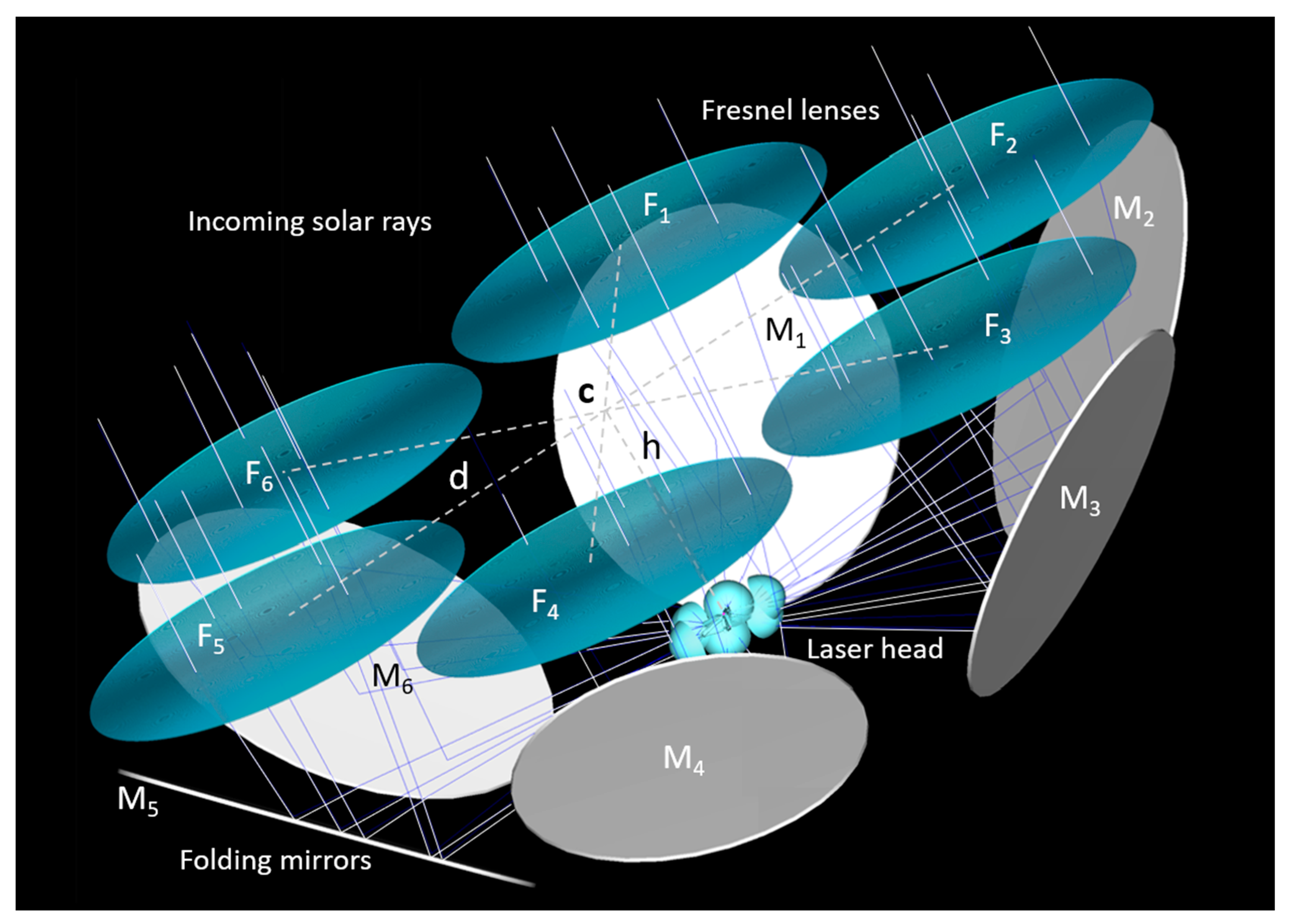
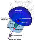
The proposed side-pumping solar laser approach (Figure 1) was composed of six circular Fresnel lenses (F1–F6) for collection and concentration of the incoming solar radiation, aligned with six plane folding mirrors (M1–M6), which redirected the concentrated solar radiation from the Fresnel lenses onto the laser head. Each Fresnel lens was centered at a distance d = 950 mm from their common optical center point C, which was placed at a height h = 551 mm above the center of the laser head, as indicated in Figure 1. The plane folding mirrors had an inclination angle of 45° in relation to their common optical axis and were located below their respective Fresnel lenses. In ZEMAX® non-sequential analysis, the radius parameter defines the radius of curvature of the Fresnel lens. For this system, an optimum radius of curvature of 700 mm was used, corresponding to a focal length of approximately 1.5 m. The Fresnel lenses were made of polymethyl methacrylate, which has high transmission efficiency for both visible and near-infrared wavelengths between 350 and 900 nm. Each one of the 3 mm thick Fresnel lenses had a radius of 461 mm, summing a total collection area of 4 m2. For the whole solar spectrum, an averaged transmission efficiency of 84% was numerically attained for the Fresnel lenses. For 950 W/m2 terrestrial solar irradiance and 95% reflectivity plane folding mirrors, a total of 3032 W solar power was assumed to reach the laser head.
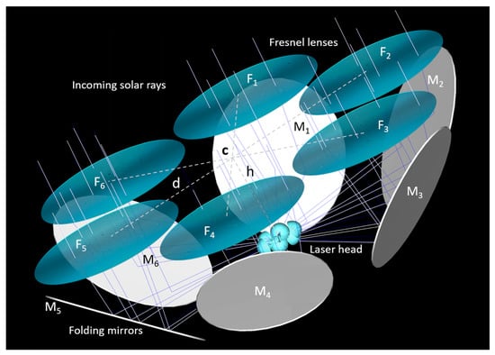
Figure 1.
Six Fresnel lens solar laser side-pumping concept with 4.0 m2 total collection area. F1–F6 and M1–M6 indicate the six Fresnel lenses and the six folding mirrors, respectively. Each Fresnel lens was symmetrically positioned at a distance d = 950 mm from their common optical center point C and at a height of h = 551 mm from the center of the laser head.
2.2. Solar Laser Head with Six Aspheric Lenses and Six Twisted Light Guides
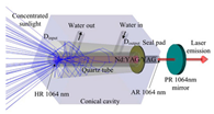
For a high focusing of the solar radiation into the Nd:YAG laser rod, six fused silica aspheric concentrators, and six twisted fused silica light guides were designed, as presented in Figure 2. Fused silica with high quality (99.999%) can be obtained through optical machining and polishing [56]. Its transparency over the visible region of the solar emission spectrum, low coefficient of thermal expansion, and high resistance to scratching and thermal endurance are optimal characteristics for Nd:YAG laser rod pumping. The six aspheric lenses were all equally designed to efficiently couple the concentrated solar radiation from the focal zone of each Fresnel lens onto the input face of each twisted light guide. Each optimized aspheric concentrator had 112 mm diameter, 53 mm height, −53 mm rear radius, and −0.150 rear conic value, and all were symmetrically positioned 96.5 mm away from the center of the laser head. An averaged transmission efficiency of 87% was numerically determined for the fused silica aspheric lenses, each one focusing 440 W solar power.
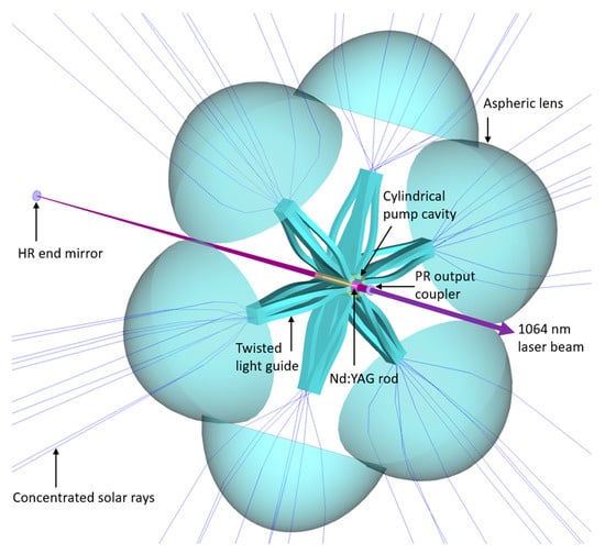
Figure 2.
Three-dimensional view of the six secondary aspheric lenses, the six twisted light guides, the cylindrical pump cavity, and the Nd:YAG rod, and the high reflection (HR) end mirror and the partial reflection (PR) output coupler, which compose the resonant cavity.
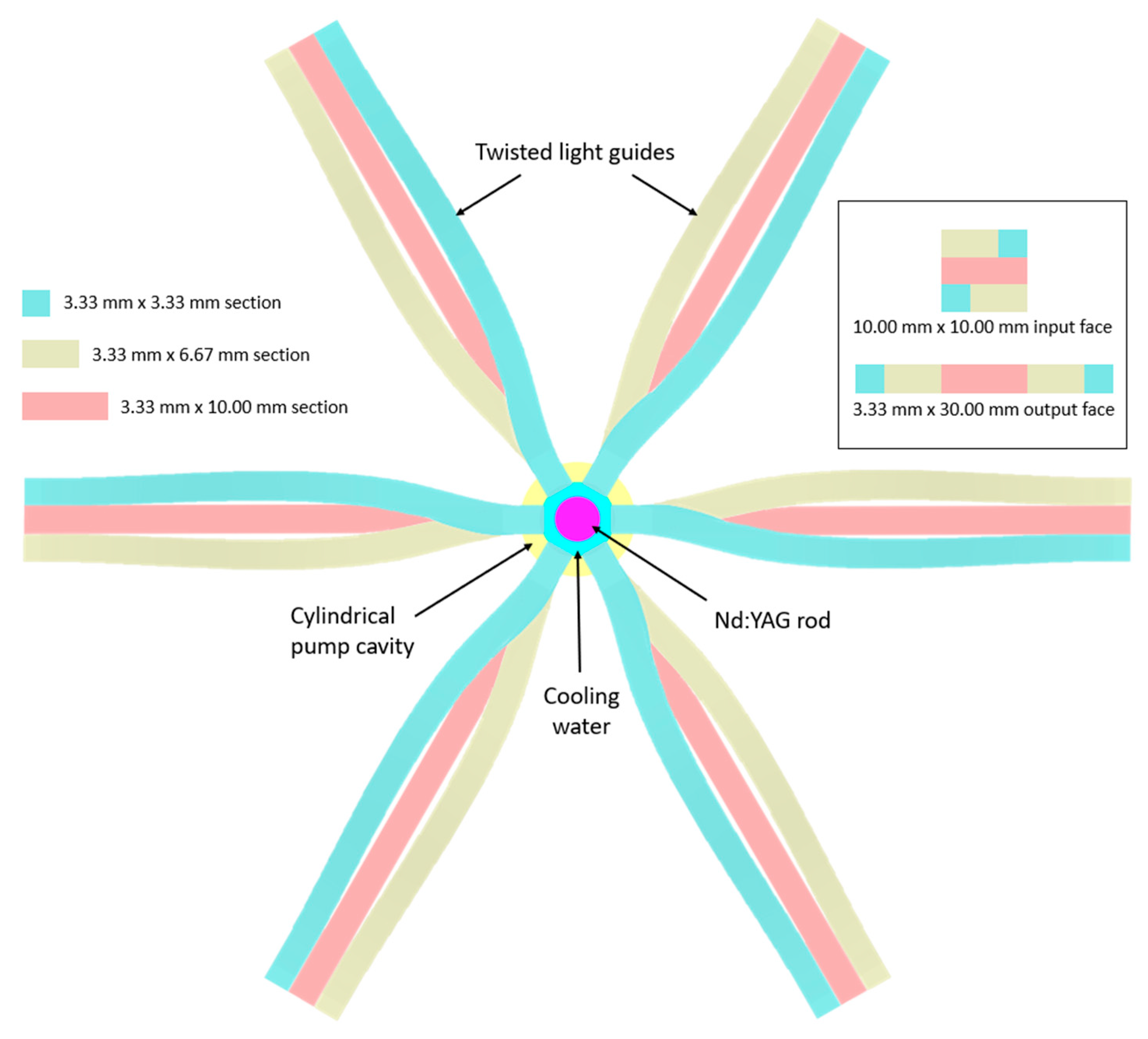
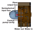
The concentrated solar radiation was then transmitted through six twisted fused silica light guides with 10.00 × 10.00 mm input face, 62.50 mm length, and 3.33 × 30.00 mm output end, experiencing the principles of refraction and total internal reflection, as demonstrated in Figure 3 and Figure 4. The six twisted light guides were designed with AutoCAD software and evenly redistributed at 4 mm from the center of the laser head in order to deliver efficiently the concentrated solar radiation from each aspheric lens. Figure 3 shows that each one of the twisted light guides was composed of five sections: the 3.33 × 10.00 mm central section, two 3.33 × 6.67 mm sections, and two 3.33 × 3.33 mm sections. As illustrated in Figure 3 inset, at the guide’s input face, the five sections were arranged in a 10.0 × 10.00 mm square cross-section, and at its output end, they became a single column with 3.33 × 30.00 mm rectangular cross-section.
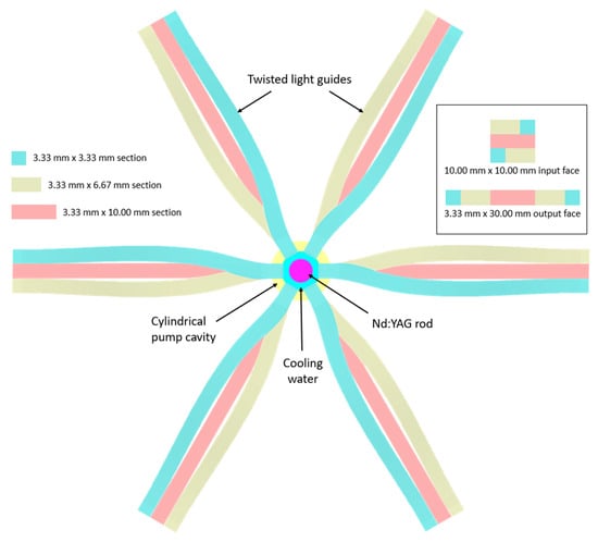
Figure 3.
Cross-sectional view of the six twisted light guides assembled for distributing the concentrated solar radiation from the aspheric lenses into the laser rod. Each one of the twisted light guides was composed of five sections: the 3.33 × 10 mm central section, two 3.33 × 6.67 mm sections, and two 3.33 × 3.33 mm sections. The inset represents the top-view of the light guide input and output faces.

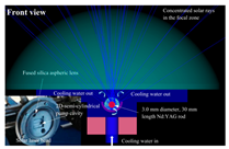
Figure 4.
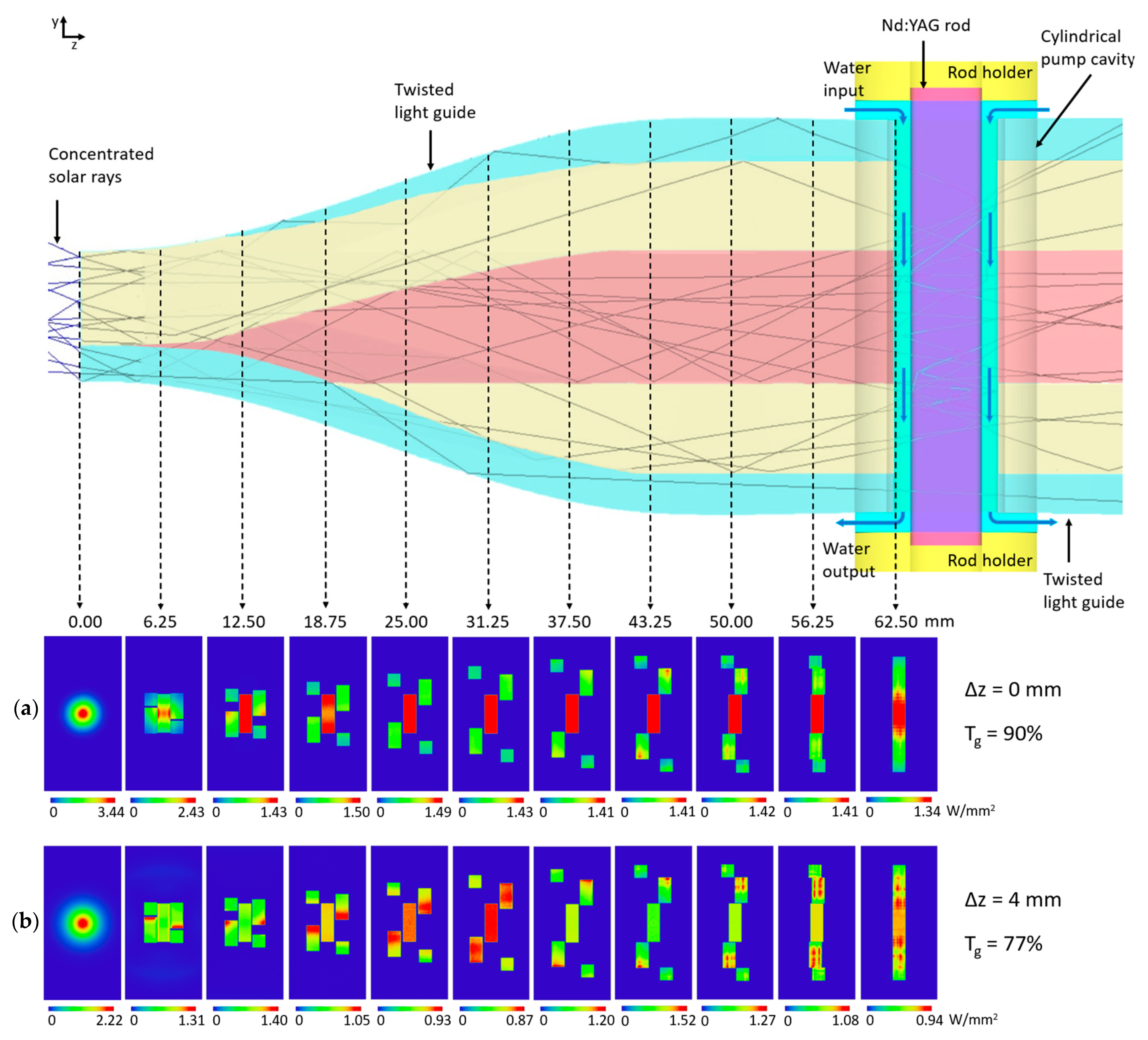
Pump light transmission through the twisted light guides. Only one twisted light guide is entirely shown to indicate how the solar rays were delivered into the laser rod inside the cylindrical pump cavity with cooling water. Pump light distribution at several cross-sections along one twisted light guide is also presented for the case of (a) optimum alignment between each aspheric lens and the input face of each light guide, and (b) shifting of the aspheric lens 4 mm upwards, resulting in a reduced transmission efficiency (Tg). Notice that the figure is not at scale.
Figure 4 gives the pump light distribution at several cross-sections for one twisted light guide. Maximum transmission is indicated with red color, whereas blue means almost none or zero pump light transmission. In order to obtain the maximum energy transmission, the optimum alignment between each aspheric lens and the input face of each light guide in the z-axis (∆z = 0) was determined. In this case, an averaged transmission efficiency of 90% was computed for the twisted light guides, each one delivering 396 W solar power into the cylindrical cavity (396 W × 6 = 2376 W total solar power). The contribution of the water layer was also included in the simulations, with the laser rod receiving at its surface a total of 1995 W concentrated solar power. However, about 50% of the energy was transmitted through the central section of each light guide, producing a non-uniform output power distribution, as demonstrated in Figure 4a. By shifting each aspheric lens by 4 mm upwards, it was possible to find a more uniform power distribution at the light guide’s output end (Figure 4b), but the misalignment significantly reduced the light guide’s averaged transmission efficiency to only 77%, and thus the shifting was not adopted.
As shown in Figure 3 and Figure 4, a single 5.5 mm diameter, 35.0 mm length Nd:YAG rod was placed at the center of a cylindrical pump cavity (95% reflectivity inner surface) with a 9 mm internal diameter and 30.0 mm height. The Nd:YAG rod was cooled with water flowing inside the pump cavity along 32.5 mm of its longitudinal surface and was mechanically fixed on each side by two holders. A total of 1064 nm antireflection (AR) coating was considered for both Nd:YAG rod end faces. The 1064 nm HR mirror and the PR output coupler formed the laser resonator, as indicated in Figure 2.
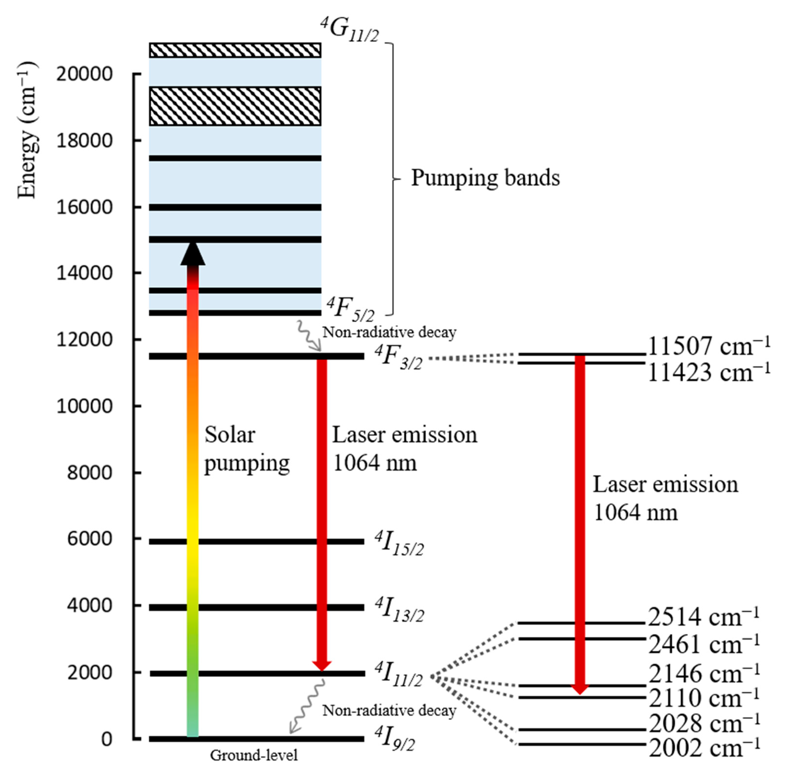
Different laser active materials can be used in order to directly convert broad-band sunlight into monochromatic radiation [57,58,59]. Despite the correlation between the solar spectrum and the absorption spectrum of Nd:YAG being only 16%, its extraordinary spectroscopical properties [60] and great thermomechanical characteristics [40] that provide resilience and durability, combined with its easy availability and relatively low cost, have attracted researchers to use this laser material in the extreme thermal and optical conditions of solar pumping. Moreover, the Nd:YAG laser is a four-level laser system. This means that the lower laser level is well above the ground state and is quickly depopulated by multiple phonon transitions, avoiding reabsorption of the laser radiation, reducing the threshold pump power, and consequently facilitating stimulated emission. As presented in Figure 5, the laser photons are typically emitted at a wavelength of 1064 nm, corresponding to the transition from the 4F3/2 to the 4I11/2 level [10].

Figure 5.
Simplified energy level diagram of Nd:YAG (Adapted from [10]).
2.3. Solar Laser Head Design with ZEMAX® Non-Sequential Ray-Tracing Software
Similar to previous research [42,43,46], the earlier-described design parameters of the side-pumping solar laser scheme were first optimized by the optical design software ZEMAX® software to attain maximal absorption of the pump power by the laser rod while trying to ensure a relatively smooth distribution of pump light. The 950 W/m2 solar irradiance at Earth’s surface, 16% overlap between Nd:YAG medium absorption and the solar emission spectra [61], 84% transmission efficiency through the Fresnel lenses, and 95% reflectance on the plane folding mirrors and the cylindrical pump cavity were considered in ZEMAX®. Additionally, 22 peak absorption wavelengths [43] characteristic of 1.0% Nd:YAG active material were programmed in ZEMAX® numerical data. The solar spectral irradiance (W/(m2 nm)) at each wavelength was consulted from the standard direct solar spectrum for one-and-a-half air mass [62]. Those 22 wavelengths, as well as their absorption coefficients, along with the absorption spectrum and the refractive indices of fused silica material for the aspheric concentrators and twisted light guides, and cooling water, were programmed into the glass catalog of ZEMAX® software.
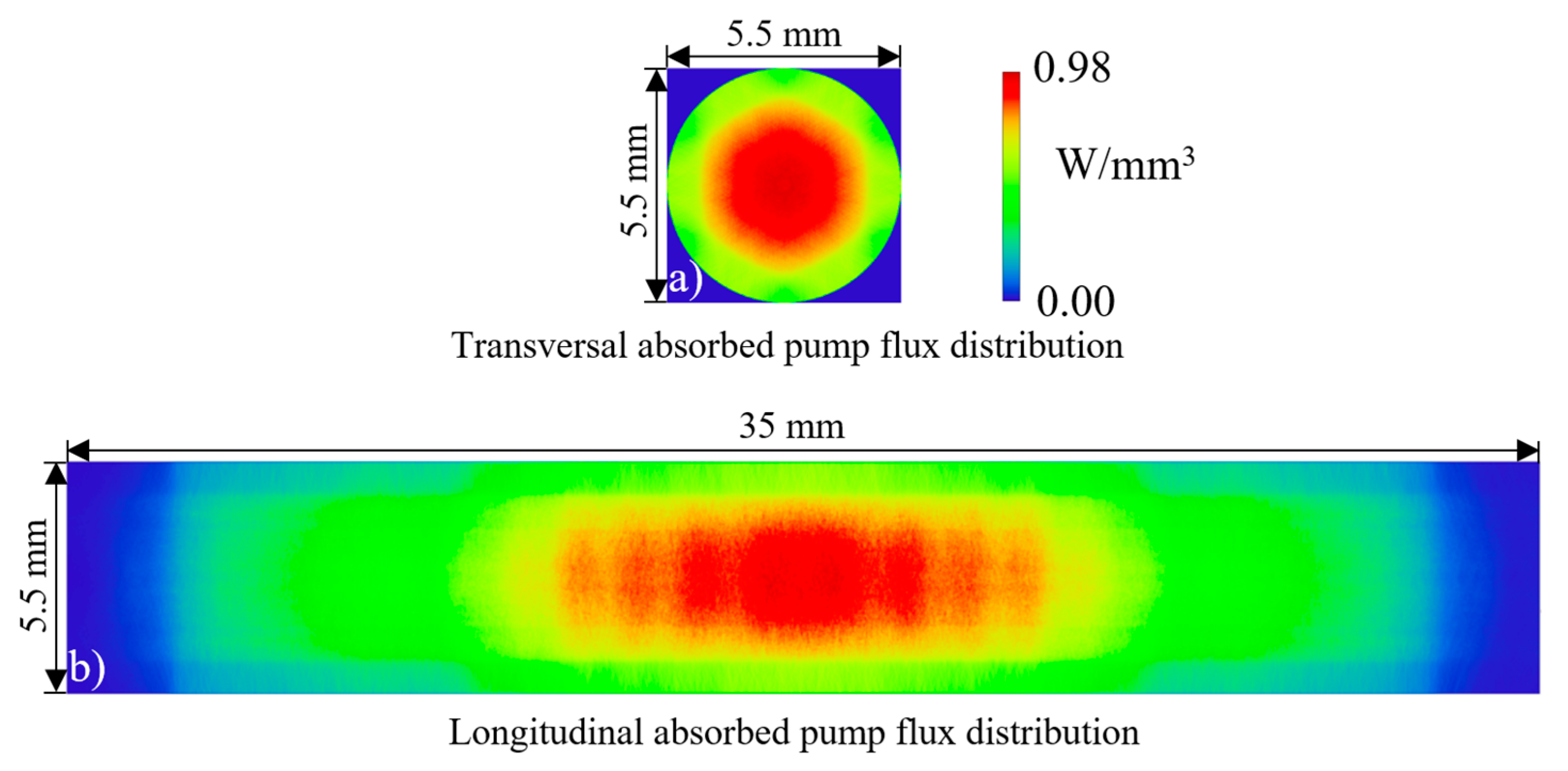
The side-pumping configuration enabled a symmetric light distribution around the laser rod with zig-zag reflections within the cylindrical cavity. The twisted fused silica light guides were fundamental in order to efficiently couple the concentrated solar radiation from the six aspheric lenses into the small-diameter cylindrical pump cavity by transforming the near-Gaussian light distribution from each aspheric concentrator into a narrow rectangular column of light at the output face of each light guide, as shown in Figure 3 and Figure 4a. This way, efficient absorption of the pump light was achieved despite the chromatic aberration of the Fresnel lenses. The pump power distribution within the active medium was analyzed by ray-tracing ZEMAX® software. A rectangular detector volume, composed of 18,000 voxels, was placed in order to entirely cover the active media. This number of voxels and a high amount of analysis rays were used for the purpose of attaining more accurate results and better image resolution. However, these two parameters had to be carefully programmed since they can highly impact the overall simulation running time. The software computes the path length of the analysis rays across each voxel regarding the absorption coefficient of the 1.0 at% Nd:YAG medium at each peak wavelength. By summing up the contributions of all voxels, a total of 317 W pump power was numerically attained with the 5.5 mm diameter, 35 mm length Nd:YAG laser rod. Figure 6 presents the absorbed energy flux distributions for its central transversal and longitudinal cross-sections. Near maximum absorption is indicated in red color, whereas blue means little or zero absorption. The Nd:YAG rod showed a rotational symmetric absorbed pump flux profile. The data were then exported from ZEMAX® software and imported to LASCAD® software, as explained in Section 2.4.
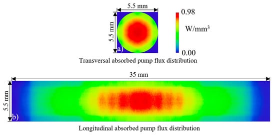
Figure 6.
Absorbed pump flux distribution along both (a) transversal and (b) longitudinal cross-sections of the 5.5 mm diameter, 35 mm length Nd:YAG laser rod.
2.4. Laser Resonator Design through LASCAD® Software
The resonant cavity for the Nd:YAG laser rod was composed of two parallel mirrors: the HR end mirror, being 1064 nm HR-coated (99.98%), and the PR output coupler being 1064-nm PR-coated (between 80% and 99%, depending on the laser rod diameter for continuous-wave operation). A 1064-nm AR coating covered each rod end face. The intensity-weighted mean of the solar wavelengths over the laser absorption bands of 660 nm was adopted in LASCAD® analysis. For 1.0 at% Nd:YAG medium, the fluorescence lifetime of 230 μs, the stimulated emission cross-section of 2.8 × 10⁻¹⁹ cm2, and the conventional absorption and scattering loss of 0.003 cm−1 were also considered [40].
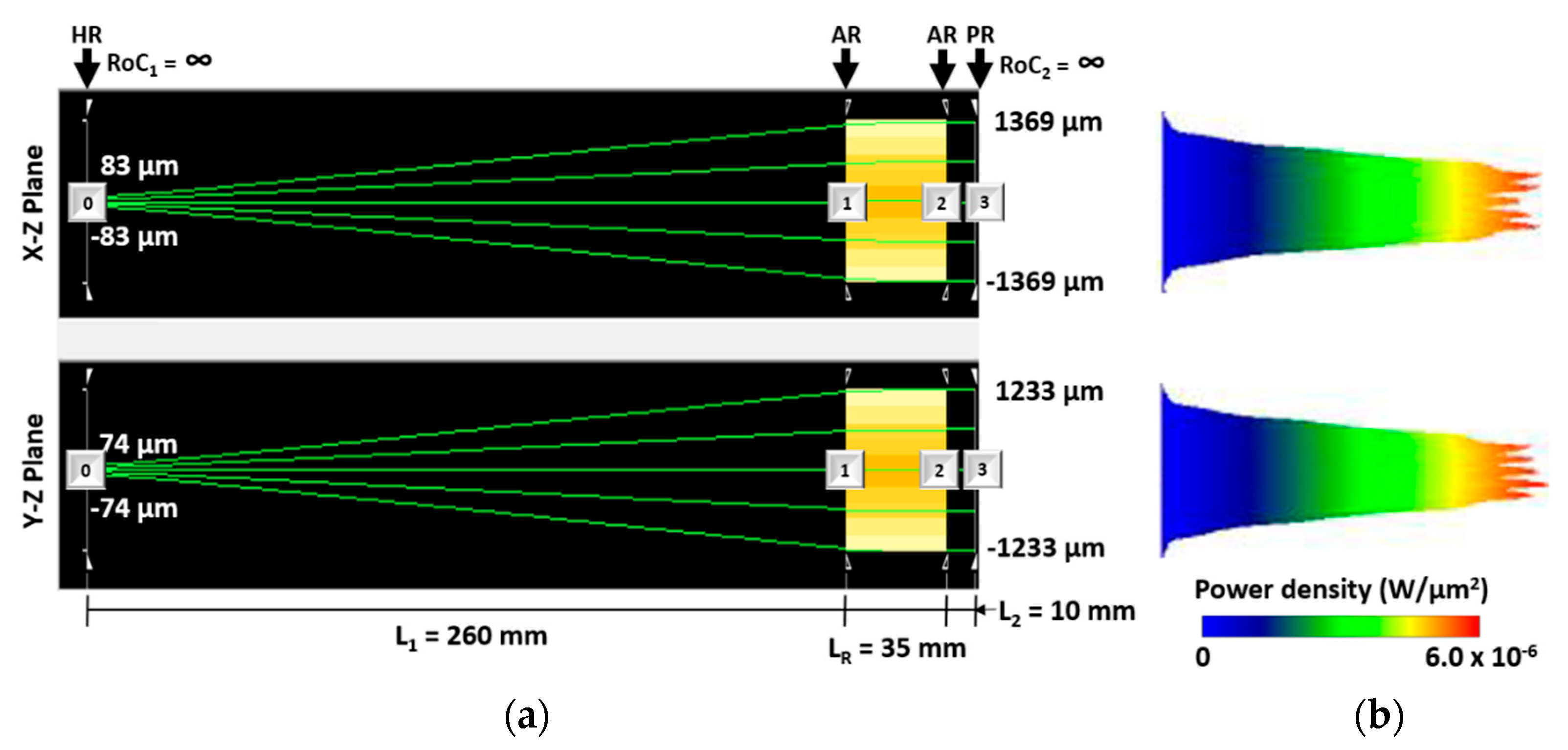
The adoption of an asymmetric resonator significantly enhances the pump and laser mode matching, providing high-quality laser beams [63]. As shown in Figure 7, L1 represents the distance from the HR mirror to the left end face of the laser rod, and L2 the distance from the right end face of the laser rod to the PR output coupler, with both being particularly important parameters in order to obtain optimum mode overlap. L2 was fixed at 10.0 mm, and L1 was optimized by LASCAD® software in order to achieve the highest pump and laser mode matching. The laser rod length is represented by LR. The radius of curvature of both the HR end mirror (RoC1) and a PR output coupler (RoC2) was also optimized. For the 5.5 mm diameter, 35 mm length rod, as indicated in Figure 7a, optimum laser design parameter was found at L1 = 260.0 mm. At the output mirror, a top hat profile with a maximum power density of 6.0 × 10⁻⁶ W/μm2 was verified, as shown in Figure 7b.

Figure 7.
Laser cavity analysis with LASCAD® software: (a) Representation of the asymmetric laser cavity for efficient laser power extraction from the 5.5 mm diameter rod and (b) the respective beam profile. L1 represents the distance from the HR mirror to the AR coating on the left rod end face, and L2 is the distance from the AR coating on the right rod end face to the PR output coupler. The laser rod length is represented by LR.
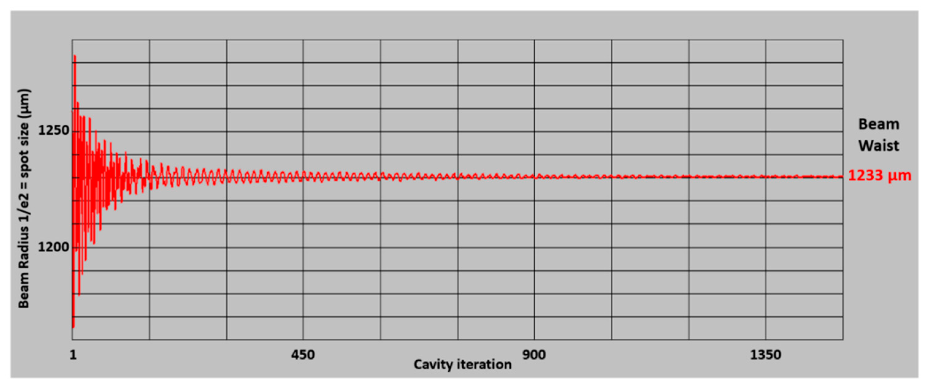
The beam waist was calculated by the beam propagation method (BPM) cavity iterations function of LASCAD® software for the top hat profile extracted from the 5.5 mm diameter laser rod within the laser cavity presented in Figure 7a. Figure 8 shows that the 1/e2 width beam waist value stabilizes at ω = 1233.0 μm.

Figure 8.
Laser beam waist at output mirror calculation by BPM cavity iterations function of LASCAD® software for the top hat profile extracted from the 5.5 mm diameter laser rod considering L1 = 260 mm.
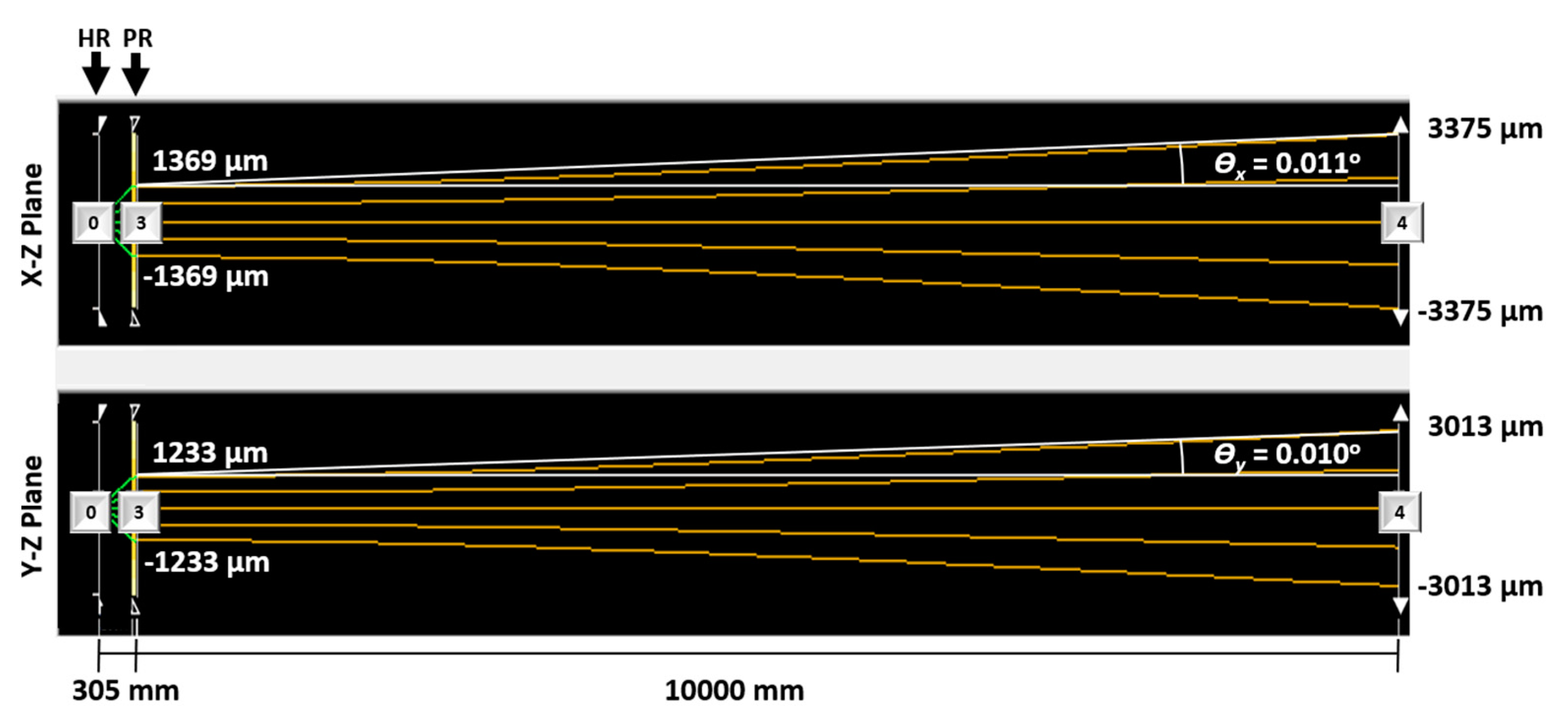
In order to evaluate the laser beam behavior during propagation, the laser beam divergence half-angles through 10,000 mm vacuum were calculated at the X-Z and Y-Z planes, being ϴx = 0.011° and ϴy = 0.010°, respectively. Figure 9 presents the LASCAD® representation of the laser beam propagation. After 10,000 mm, the 1/e2 width beam waist value only increased from ω = 1233.0 μm to ω = 3013.0 μm.
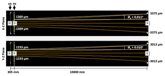
Figure 9.
LASCAD® representation of the laser beam propagation through 10,000 mm vacuum. ϴx and ϴy represent the laser beam divergence half-angles at the X-Z and Y-Z planes, respectively.
3. Results
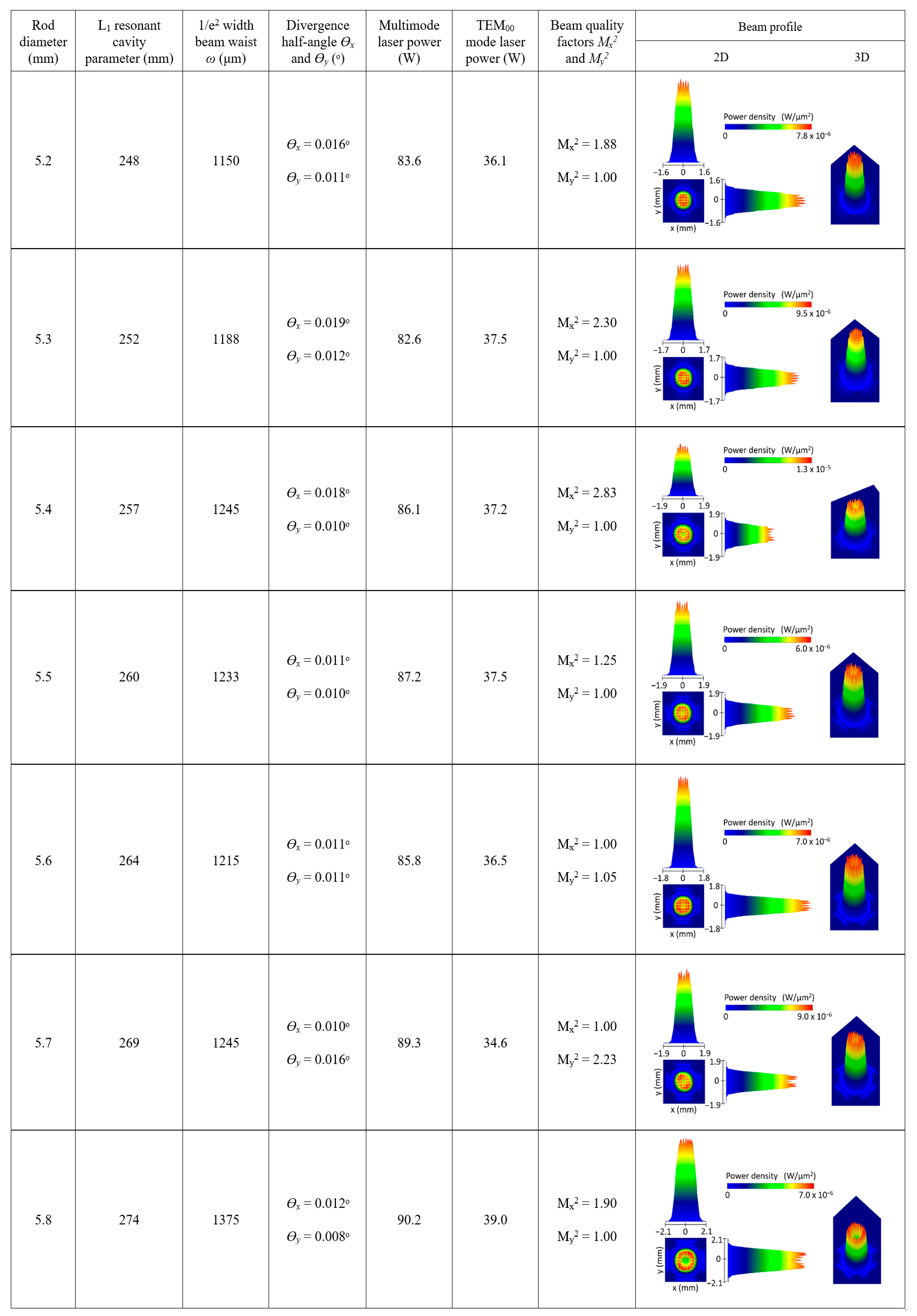
Based on the previously described parameters, multimode solar laser power, TEM00 mode laser power, and M2 beam quality factors at the x and y-axis were calculated with the LASCAD® software. The numerical calculated TEM00 mode laser power corresponded to the fundamental mode within the obtained beam profile. The above-described laser resonant cavity was optimized for several laser rod diameters. Both the HR end mirror and the PR output coupler remained plane (RoC1 = RoC2 = ∞), the L2 resonant cavity parameter was fixed at 10 mm, and L1 was optimized in order to achieve the best overlap between the pump and the laser mode volumes for each case. Figure 10 shows the strong influence of the Nd:YAG laser rod diameter on the laser beam profile calculated through LASCAD® analysis. The laser beam profile revealed a top hat shape for the 5.2, 5.3, 5.4, 5.5, and 5.6 mm laser rod diameters. As the rod diameter increased, the laser beam profile showed lower energy in its center, and a doughnut-shaped laser beam profile emerged from the 5.8 mm Nd:YAG laser rod diameter. The L1 resonant cavity parameter, the 1/e2 width beam waist value ω, the laser beam divergence half-angles at the X-Z and Y-Z planes (ϴx and ϴy, respectively), the multimode and TEM00 mode laser power, the laser beam quality factors Mx2 and My2 and the 2D and 3D view of the laser beam profile are also presented in Figure 10 as a function of the laser rod diameter.

Figure 10.
Summary of the laser beam profiles obtained as a function of the Nd:YAG laser rod diameter through LASCAD® analysis.
Figure 11a presents the 3D view of the top hat laser beam profile obtained from the 5.5 mm diameter laser rod with beam quality factors of Mx2 = 1.25, My2 = 1.00, and TEM00 mode laser power of 37.5 W. For the doughnut-shaped laser beam profile obtained from the 5.8 mm laser rod diameter, 39.0 W TEM00 mode laser power was numerically attained, with beam quality factors of Mx2 = 1.90, My2 = 1.00, as shown in Figure 11b.
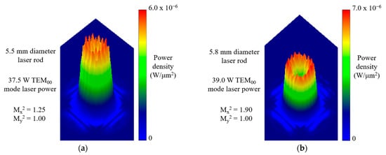
Figure 11.
Numerically simulated 3D laser beam profile for (a) the 5.5 mm diameter and (b) the 5.8 mm diameter laser rods.
4. Discussion
The previously presented results demonstrate, to the best of our knowledge, the first numerical simulation of doughnut-shaped and top hat solar laser beam profiles. The light guides were essential to symmetrically side-pumped the laser rod with six narrow rectangular pump columns, whereas the laser rod diameter was the key parameter to obtain different laser beam profiles. Table 2 establishes the comparison between the present work and the experimental/numerical records for collection and solar-to-TEM00/multimode power conversion efficiencies for the top hat, doughnut-shaped, and multimode solar laser beams. A top hat laser beam profile with 9.4 W/m2 collection efficiency and 0.99% solar-to-TEM00 mode power conversion efficiency was obtained from the 5.5 mm diameter laser rod. As far as we know, this kind of solar laser beam was never reported in experimental essays. A doughnut-shaped laser beam was also numerically attained, from the 5.8 mm diameter laser rod, with 9.8 W/m2 TEM00 mode laser power collection and 1.03% solar-to-TEM00 mode power conversion efficiencies, corresponding to an increase of 2.2 and 1.9 times, respectively, compared to the current experimental record for doughnut-shaped solar laser power achieved by Vistas et al. [52]. As experimentally demonstrated by Liang et al. [50], TEM01* mode laser beam profiles, commonly known as doughnut-shaped, showed only slightly higher laser power than TEM00 mode laser beam profiles, regarding similar pumping conditions. Hence, the numerically calculated TEM00 mode laser power can be a suitable approximation of the TEM01* mode laser power. The 90.2 W multimode solar laser power was obtained with the 5.8 mm laser rod diameter, corresponding to 22.6 W/m2 collection and 2.37% solar-to-multimode power conversion efficiencies, similar to the previous experimental results regarding solar laser side-pumping configurations [50]. Therefore, the novel solar laser configuration numerically demonstrated the ability to produce doughnut-shaped and top hat laser beams, with major importance for the industry, while competing in efficiency with the most advanced solar laser systems so far.
Table 2.
Comparison between the present work and the experimental or numerical records for collection and solar-to-TEM00/multimode power conversion efficiencies for the top hat, doughnut-shaped (TEM01* mode), and multimode solar laser beams.
5. Conclusions
As far as we know, the novel solar laser system reported here successfully accomplished the first numerical analysis on the efficient generation of doughnut-shaped and top hat solar laser beam profiles. The solar energy was firstly collected and concentrated by six Fresnel lenses and then redirected toward six secondary concentrators through six plane folding mirrors. The secondary fused silica concentrators further compressed the solar radiation onto the six twisted fused silica light guides that transformed the incident near-Gaussian energy distribution into a narrow rectangular pump column, allowing a symmetrical side-pumping around the 5.5 mm diameter, 35 mm length Nd:YAG laser rod inside a cylindrical cavity with water cooling. An asymmetric resonator ensured an optimum mode overlap. A top hat laser beam profile (Mx2 = 1.25, My2 = 1.00) was computed through both ZEMAX® and LASCAD® analysis, with 9.4 W/m2 TEM00 mode laser power collection and 0.99% solar-to-TEM00 mode power conversion efficiencies. By using a 5.8 mm laser rod diameter, a doughnut-shaped solar laser beam profile (Mx2 = 1.90, My2 = 1.00) was also produced. The 90.2 W multimode solar laser power was attained with the 5.8 mm laser rod diameter, corresponding to 22.6 W/m2 collection and 2.37% solar-to-multimode power conversion efficiencies, similar to the previous experimental results regarding solar laser side-pumping configurations [50]. These results demonstrated the laser rod diameter as a key parameter to accomplish top hat and doughnut-shaped laser beams. Even though doughnut-shaped solar laser beams were already experimentally obtained, the methods to produce them were not fully exploited. Hence, the first numerical simulation of doughnut-shaped and top hat solar laser beam profiles reported here significantly contributes to understanding how to generate such beams, particularly the top hat solar laser beam that was not yet demonstrated in practical essays. Future research aims to experimentally validate the results obtained here for both the top hat and doughnut-shaped laser beam profiles. The major barrier to the application of this technology is related to the availability of solar radiation at Earth’s surface. Although solar energy can still be collected during cloudy days, the solar laser system’s efficiency can significantly drop. However, in space, solar radiation is a more reliable resource, and, as demonstrated here, the difference between these solar laser beams can be useful for future communications systems. Upcoming advancements may expand solar-pumped laser applications into new areas and provide an alternative cost-effective approach to generate these laser beam profiles, essential for high accuracy laser materials processing, particularly at nanoscale.
Author Contributions
Conceptualization, D.L. and M.C.; methodology, M.C., D.L., J.A. and C.R.V.; software, M.C., D.L., C.R.V., H.C. and D.G.; validation, M.C. and D.L.; formal analysis, M.C., D.L., C.R.V. and D.G.; investigation, M.C. and D.L.; resources, D.L. and J.A.; data curation, M.C. and D.L.; writing—original draft preparation, M.C.; writing—review and editing, M.C., D.L., C.R.V., D.G., B.D.T., H.C. and J.A.; visualization, M.C.; supervision, D.L. and C.R.V.; project administration, D.L.; funding acquisition, D.L. All authors have read and agreed to the published version of the manuscript.
Funding
This research was funded by Fundação para a Ciência e a Tecnologia—Ministério da Ciência, Tecnologia e Ensino Superior, grant number UIDB/00068/2020.
Institutional Review Board Statement
Not applicable.
Informed Consent Statement
Not applicable.
Data Availability Statement
Not applicable.
Acknowledgments
The fellowship grants SFRH/BD/145322/2019, PD/BD/142827/2018, PD/BD/128267/2016, SFRH/BPD/125116/2016 and CEECIND/03081/2017 of Miguel Catela, Dario Garcia, Bruno D. Tibúrcio Cláudia R. Vistas and Joana Almeida, respectively, are acknowledged.
Conflicts of Interest
The authors declare no conflict of interest. The funders had no role in the design of the study, in the collection, analyses, or interpretation of data, in the writing of the manuscript, or in the decision to publish the results.
References
- Liang, D.; Almeida, J. Highly efficient solar-pumped Nd:YAG laser. Opt. Express 2011, 19, 26399. [Google Scholar] [CrossRef]
- Summerer, L.; Purcell, O. Concepts for Wireless Energy Transmission via Laser. ESA-Adv. Concepts Team 2008, 1–10. [Google Scholar]
- Hemmati, H.; Biswas, A.; Djordjevic, I.B. Deep-space optical communications: Future perspectives and applications. Proc. IEEE 2011, 99, 2020–2039. [Google Scholar] [CrossRef]
- Lando, M.; Kagan, J.A.; Shimony, Y.; Kalisky, Y.Y.; Noter, Y.; Yogev, A.; Rotman, S.R.; Rosenwaks, S. Solar-pumped solid state laser program. In Proceedings of the 10th Meeting on Optical Engineering in Israel, Tel-Aviv, Israel, 1–6 March 1997; Shaldov, I., Rotman, S.R., Eds.; SPIE: Jerusalem, Israel, 1997; Volume 3110, pp. 196–201. [Google Scholar]
- Rather, J.D.G.; Gerry, E.T.; Zeiders, G.W. Investigation of possibilities for solar powered high energy lasers in space. NASA Tech. Rep. Serv. 1977. Available online: https://ntrs.nasa.gov/search.jsp?R=19770019534 (accessed on 13 May 2021).
- Vasile, M.; Maddock, C.A. Design of a formation of solar pumped lasers for asteroid deflection. Adv. Sp. Res. 2012, 50, 891–905. [Google Scholar] [CrossRef] [Green Version]
- Yabe, T.; Uchida, S.; Ikuta, K.; Yoshida, K.; Baasandash, C.; Mohamed, M.S.; Sakurai, Y.; Ogata, Y.; Tuji, M.; Mori, Y.; et al. Demonstrated fossil-fuel-free energy cycle using magnesium and laser. Appl. Phys. Lett. 2006, 89, 261107. [Google Scholar] [CrossRef]
- Graydon, O. A sunny solution. Nat. Photonics 2007, 1, 495–496. [Google Scholar] [CrossRef]
- Oliveira, M.; Liang, D.; Almeida, J.; Vistas, C.R.; Gonçalves, F.; Martins, R. A path to renewable Mg reduction from MgO by a continuous-wave Cr:Nd:YAG ceramic solar laser. Sol. Energy Mater. Sol. Cells 2016, 155, 430–435. [Google Scholar] [CrossRef]
- Koechner, W. Solid-State Laser Engineerings, 6th ed.; Springer: New York, NY, USA, 2006; ISBN 978-0-387-29338-7. [Google Scholar]
- Duocastella, M.; Arnold, C.B. Bessel and annular beams for materials processing. Laser Photonics Rev. 2012, 6, 607–621. [Google Scholar] [CrossRef]
- Le, H.; Penchev, P.; Henrottin, A.; Bruneel, D.; Nasrollahi, V.; Ramos-de-Campos, J.A.; Dimov, S. Effects of top-hat laser beam processing and scanning strategies in laser micro-structuring. Micromachines 2020, 11, 221. [Google Scholar] [CrossRef] [Green Version]
- Dickey, F.M.; Holswade, S.C. Laser Beam Shaping, Theory and Techniques; Marcel Dekker, Inc.: New York, NY, USA; Basel, Switzerland, 2000; ISBN 9780735405752. [Google Scholar]
- Grojean, R.E.; Feldman, D.; Roach, J.F. Production of flat top beam profiles for high energy lasers. Rev. Sci. Instrum. 1980, 51, 375–376. [Google Scholar] [CrossRef] [PubMed]
- Frieden, B.R. Lossless Conversion of a Plane Laser Wave to a Plane Wave of Uniform Irradiance. Appl. Opt. 1965, 4, 1400. [Google Scholar] [CrossRef]
- Hoffnagle, J.A.; Jefferson, C.M. Design and performance of a refractive optical system that converts a Gaussian to a flattop beam. Appl. Opt. 2000, 39, 5488. [Google Scholar] [CrossRef]
- Duerr, F.; Thienpont, H. Refractive laser beam shaping by means of a functional differential equation based design approach. Opt. Express 2014, 22, 8001. [Google Scholar] [CrossRef] [PubMed]
- Leger, J.R.; Chen, D.; Wang, Z. Diffractive optical element for mode shaping of a Nd:YAG laser. Opt. Lett. 1994, 19, 108. [Google Scholar] [CrossRef]
- Dickey, F.M. Gaussian laser beam profile shaping. Opt. Eng. 1996, 35, 3285. [Google Scholar] [CrossRef]
- Račiukaitis, G.; Stankevičius, E.; Gečys, P.; Gedvilas, M.; Bischoff, C.; Jäger, E.; Umhofer, U.; Völklein, F. Laser processing by using diffractive optical laser beam shaping technique. J. Laser Micro Nanoeng. 2011, 6, 37–43. [Google Scholar] [CrossRef]
- Ding, X.Y.; Ren, Y.X.; Lu, R. De Shaping super-Gaussian beam through digital micro-mirror device. Sci. China Phys. Mech. Astron. 2015, 58, 1–6. [Google Scholar] [CrossRef]
- Forbes, A.; Dudley, A.; McLaren, M. Creation and detection of optical modes with spatial light modulators. Adv. Opt. Photonics 2016, 8, 200. [Google Scholar] [CrossRef]
- Litvin, I.A.; Forbes, A. Intra cavity flat top beam generation. Opt. Express 2009, 17, 15891–15903. [Google Scholar] [CrossRef] [Green Version]
- Litvin, I.A.; King, G.; Strauss, H. Beam shaping laser with controllable gain. Appl. Phys. B Lasers Opt. 2017, 123, 1–5. [Google Scholar] [CrossRef]
- Kana, E.T.; Bollanti, S.; Di Lazzaro, P.; Murra, D.; Bouba, O.; Onana, M.B. Laser beam homogenization: Modeling and comparison with experimental results. Opt. Commun. 2006, 264, 187–192. [Google Scholar] [CrossRef]
- Wallace, L. Efficient Transformation of Gaussian Beams into Uniform, Rectangular Intensity Distributions; Coherent, Inc.: Santa Clara, CA, USA, 2011. [Google Scholar]
- Homburg, O.; Mitra, T. Gaussian-to-top-hat beam shaping: An overview of parameters, methods, and applications. In Proceedings of the Laser Reson. Microresonators Beam Control XIV, San Francisco, CA, USA, 21–26 January 2012; Volume 8236, p. 82360A. [Google Scholar] [CrossRef]
- Hracek, B.; Bäuerle, H. New Ways to Generate Flat-Top Profiles. Opt. Photonik 2015, 10, 16–18. [Google Scholar] [CrossRef]
- Santarsiero, M.; Borghi, R. Correspondence between super-Gaussian and flattened Gaussian beams. J. Opt. Soc. Am. A 1999, 16, 188–190. [Google Scholar] [CrossRef]
- Shealy, D.L.; Hoffnagle, J.A. Laser beam shaping profiles and propagation. Appl. Opt. 2006, 45, 5118–5131. [Google Scholar] [CrossRef]
- Kaszei, K.; Boone, C. Flat-Top Laser Beams: Their Uses and Benefits. Available online: https://www.laserfocusworld.com/optics/article/14197298/flattop-laser-beams-their-uses-and-benefits (accessed on 17 May 2021).
- Fuse, K. Beam Shaping for Advanced Laser Materials Processing. Laser Tech. J. 2015, 12, 19–22. [Google Scholar] [CrossRef] [Green Version]
- Hung, Y.-J.; Chang, H.-J.; Chang, P.-C.; Lin, J.-J.; Kao, T.-C. Employing refractive beam shaping in a Lloyd’s interference lithography system for uniform periodic nanostructure formation. J. Vac. Sci. Technol. B Nanotechnol. Microelectron. Mater. Process. Meas. Phenom. 2017, 35, 030601. [Google Scholar] [CrossRef]
- Ramos, S.; Stork, W.; Heussner, N. Multiple-pulse damage thresholds of retinal explants using top hat profiles. In Proceedings of the Optical Interactions with Tissue and Cells XXXI, San Francisco, CA, USA, 1–2 February 2020; Volume 11238, p. 112380D. [Google Scholar] [CrossRef]
- Zhang, Y.; Wu, C.; Song, Y.; Si, K.; Zheng, Y.; Hu, L.; Chen, J.; Tang, L.; Gong, W. Machine learning based adaptive optics for doughnut-shaped beam. Opt. Express 2019, 27, 16871. [Google Scholar] [CrossRef]
- Tumkur, T.U.; Voisin, T.; Shi, R.; Depond, P.J.; Roehling, T.T.; Wu, S.; Crumb, M.F.; Roehling, J.D.; Guss, G.; Khairallah, S.A.; et al. Nondiffractive beam shaping for enhanced optothermal control in metal additive manufacturing. Sci. Adv. 2021, 7, 9358–9373. [Google Scholar] [CrossRef]
- Kiss, Z.J.; Lewis, H.R.; Duncan, R.C. Sun pumped continuous optical maser. Appl. Phys. Lett. 1963, 2, 93–94. [Google Scholar] [CrossRef]
- Maiman, T.H. Stimulated optical radiation in Ruby. Nature 1960, 187, 493–494. [Google Scholar] [CrossRef]
- Arashi, H.; Oka, Y.; Sasahara, N.; Kaimai, A.; Ishigame, M. A Solar-Pumped cw 18 W Nd:YAG Laser. Jpn. J. Appl. Phys. 1984, 23, 1051–1053. [Google Scholar] [CrossRef]
- Weksler, M.; Shwartz, J. Solar-pumped solid-state lasers. IEEE J. Quantum Electron. 1988, 24, 1222–1228. [Google Scholar] [CrossRef]
- Lando, M.; Kagan, J.; Linyekin, B.; Dobrusin, V. A solar-pumped Nd:YAG laser in the high collection efficiency regime. Opt. Commun. 2003, 222, 371–381. [Google Scholar] [CrossRef]
- Liang, D.; Almeida, J.; Vistas, C.R.; Guillot, E. Solar-pumped Nd:YAG laser with 31.5 W/m2 multimode and 7.9 W/m2 TEM00-mode collection efficiencies. Sol. Energy Mater. Sol. Cells 2017, 159, 435–439. [Google Scholar] [CrossRef]
- Liang, D.; Vistas, C.R.; Tibúrcio, B.D.; Almeida, J. Solar-pumped Cr:Nd:YAG ceramic laser with 6.7% slope efficiency. Sol. Energy Mater. Sol. Cells 2018, 185, 75–79. [Google Scholar] [CrossRef]
- Yabe, T.; Ohkubo, T.; Uchida, S.; Yoshida, K.; Nakatsuka, M.; Funatsu, T.; Mabuti, A.; Oyama, A.; Nakagawa, K.; Oishi, T.; et al. High-efficiency and economical solar-energy-pumped laser with Fresnel lens and chromium codoped laser medium. Appl. Phys. Lett. 2007, 90, 261120. [Google Scholar] [CrossRef]
- Dinh, T.H.; Ohkubo, T.; Yabe, T.; Kuboyama, H. 120 watt continuous wave solar-pumped laser with a liquid light-guide lens and an Nd:YAG rod. Opt. Lett. 2012, 37, 2670–2672. [Google Scholar] [CrossRef]
- Liang, D.; Almeida, J. Solar-Pumped TEM00 Mode Nd:YAG laser. Opt. Express 2013, 21, 25107. [Google Scholar] [CrossRef] [PubMed]
- Xu, P.; Yang, S.; Zhao, C.; Guan, Z.; Wang, H.; Zhang, Y.; Zhang, H.; He, T. High-efficiency solar-pumped laser with a grooved Nd:YAG rod. Appl. Opt. 2014, 53, 3941–3944. [Google Scholar] [CrossRef]
- Guan, Z.; Zhao, C.; Li, J.; He, D.; Zhang, H. 32.1 W/m2 continuous wave solar-pumped laser with a bonding Nd:YAG/YAG rod and a Fresnel lens. Opt. Laser Technol. 2018, 107, 158–161. [Google Scholar] [CrossRef]
- Liang, D.; Almeida, J.; Tibúrcio, B.; Catela, M.; Garcia, D.; Costa, H.; Vistas, C. Seven-rod pumping approach for the most efficient production of TEM00-mode solar laser power by a Fresnel lens. J. Sol. Energy Eng. 2021, 143, 1–28. [Google Scholar] [CrossRef]
- Liang, D.; Vistas, C.R.; Almeida, J.; Tibúrcio, B.D.; Garcia, D. Side-pumped continuous-wave Nd:YAG solar laser with 5.4% slope efficiency. Sol. Energy Mater. Sol. Cells 2019, 192, 147–153. [Google Scholar] [CrossRef]
- Almeida, J.; Liang, D.; Vistas, C.R. A doughnut-shaped Nd:YAG solar laser beam. Opt. Laser Technol. 2018, 106, 1–6. [Google Scholar] [CrossRef]
- Vistas, C.R.; Liang, D.; Almeida, J.; Tibúrcio, B.D.; Garcia, D. A doughnut-shaped Nd:YAG solar laser beam with 4.5 W/m2 collection efficiency. Sol. Energy 2019, 182, 42–47. [Google Scholar] [CrossRef]
- Rioux, M.; Tremblay, R.; Bélanger, P.A. Linear, annular, and radial focusing with axicons and applications to laser machining. Appl. Opt. 1978, 17, 1532. [Google Scholar] [CrossRef]
- Cherezova, T.; Chesnokov, S.; Kaptsov, L.; Kudryashov, A. Doughnut-like laser beam output formation by intracavity flexible controlled mirror. Opt. Express 1998, 3, 180. [Google Scholar] [CrossRef]
- Litvin, I.A.; Ngcobo, S.; Naidoo, D.; Ait-Ameur, K.; Forbes, A. Doughnut laser beam as an incoherent superposition of two petal beams. Opt. Lett. 2014, 39, 704. [Google Scholar] [CrossRef] [Green Version]
- Bernardes, P.H.; Liang, D. Solid-state laser pumping by light guides. Appl. Opt. 2006, 45, 3811–3816. [Google Scholar] [CrossRef]
- Lando, M.; Shimony, Y.; Benmair, R.M.J.; Abramovich, D.; Krupkin, V.; Yogev, A. Visible solar-pumped lasers. Opt. Mater. 1999, 13, 111–115. [Google Scholar] [CrossRef]
- Liang, D.; Almeida, J.; Garcia, D. Comparative Study of Cr:Nd:YAG and Nd:YAG Solar Laser Performances. In Proceedings of the 8th Iberoamerican Optics Meeting and 11th Latin American Meeting on Optics, Lasers, and Applications, Porto, Portugal, 22–26 July 2013; Volume 8785, p. 87859Y. [Google Scholar]
- Vistas, C.R.; Liang, D.; Almeida, J.; Tibúrcio, B.D.; Garcia, D.; Catela, M.; Costa, H.; Guillot, E. Ce:Nd:YAG side-pumped solar laser. J. Photonics Energy 2021, 11, 1–9. [Google Scholar] [CrossRef]
- Lupei, V.; Lupei, A.; Gheorghe, C.; Ikesue, A. Emission sensitization processes involving Nd3+ in YAG. J. Lumin. 2016, 170, 594–601. [Google Scholar] [CrossRef]
- Zhao, B.; Zhao, C.; He, J.; Yang, S. The study of active medium for solar-pumped solid-state lasers. Acta Opt. Sin. 2007, 27, 1797–1801. [Google Scholar]
- ASTM International. ASTM Standard G173-03, Standard Tables for Reference Solar Spectral Irradiances: Direct Normal and Hemispherical on 37 Tilted Surface; ASTM: West Conshohocken, PS, USA, 2012. [Google Scholar]
- Liang, D.; Almeida, J.; Vistas, C.R.; Guillot, E. Solar-pumped TEM00 mode Nd:YAG laser by a heliostat—Parabolic mirror system. Sol. Energy Mater. Sol. Cells 2015, 134, 305–308. [Google Scholar] [CrossRef]


Publisher’s Note: MDPI stays neutral with regard to jurisdictional claims in published maps and institutional affiliations. |
© 2021 by the authors. Licensee MDPI, Basel, Switzerland. This article is an open access article distributed under the terms and conditions of the Creative Commons Attribution (CC BY) license (https://creativecommons.org/licenses/by/4.0/).