Review

Non-Destructive Diagnostic Methods for Fire-Side Corrosion Risk Assessment of Industrial Scale Boilers, Burning Low Quality Solid Biofuels—A Mini Review

1
Department of Energy Conversion Engineering, Wroclaw University of Science and Technology, Wybrzeże Wyspiańskiego 27, 50-370 Wrocław, Poland
2
Department of Chemical Engineering, Shaheed Bhagat Singh State University, Ferozepur 152004, India
3
Department of Automation, Mechatronics and Control Systems, Wroclaw University of Science and Technology, Wybrzeże Wyspiańskiego 27, 50-370 Wrocław, Poland
*
Author to whom correspondence should be addressed.
Energies 2021, 14(21), 7132; https://doi.org/10.3390/en14217132
Submission received: 28 September 2021 / Revised: 23 October 2021 / Accepted: 27 October 2021 / Published: 1 November 2021
(This article belongs to the Special Issue Modelling and Calculation of Raw Material Industry)

Abstract

:
The use of low-emission combustion technologies in power boilers has contributed to a significant increase in the rate of high-temperature corrosion in boilers and increased risk of failure. The use of low quality biomass and waste, caused by the current policies pressing on the decarbonization of the energy generation sector, might exacerbate this problem. Additionally, all of the effects of the valorization techniques on the inorganic fraction of the solid fuel have become an additional uncertainty. As a result, fast and reliable corrosion diagnostic techniques are slowly becoming a necessity to maintain the security of the energy supply for the power grid. Non-destructive testing methods (NDT) are helpful in detecting these threats. The most important NDT methods, which can be used to assess the degree of corrosion of boiler tubes, detection of the tubes’ surface roughness and the internal structural defects, have been presented in the paper. The idea of the use of optical techniques in the initial diagnosis of boiler evaporators’ surface conditions has also been presented.

Graphical Abstract

1. Introduction

The use of low-emission combustion techniques in pulverized coal-fired boilers has contributed, to a large extent, to intensifying the high-temperature corrosion processes, consequently causing the relatively quick wastage of wall tubes [1,2]. Fire-side corrosion in coal-fired boilers has been well investigated [3,4,5,6,7,8]. In general, fire-side corrosion can be subdivided into two distinct types, namely:
  • water wall (evaporator) corrosion
  • corrosion of the superheaters
The main causes of the boiler tubes high-temperature are: impurities in the fuel, such as sulphur alkali metals and chlorine; the lack of control of the combustion process resulting in a reducing gaseous environment at the tube surface; impingement of flames; and the temperature of tube metal.
The erosion-corrosion boiler tube-thick losses increase the exploitation expenses by increasing the frequency of the necessary full and partial screen replacements. They also strongly negatively affect the reliability and availability of the whole power unit. In general, the problem of the severe wastage of the wall tubes in boilers emerged a long time ago, for boilers fired with hard coal, after the modernization of their furnace systems; i.e., after staged combustion had been introduced. Reducing atmosphere can be detrimental to high-chromium heat-resisting steels with ferritic matrix, working at elevated or high temperature, making them liable to brittleness growth, as mentioned by Golanski and Lachowicz [9]. For temperatures as high as 720 °C, the presence of a regular grid or Sigma phase residue at the ferrite grain boundaries can be observed [9].
In the near future, industrial size power units will remain vitally important as power sources due to their flexible ability to cover demand when intermittent power sources are incapable of supplying the energy to the grid [10]. The ability to utilize biomass in these units will allow them to decrease their carbon footprint while maintaining the energy supply security for the grid. However, due to the inherently high variability of biomass, in terms of its properties, even the use of novel valorization techniques might not alleviate the problem completely. Therefore, there is a need for quick and reliable corrosion diagnostics techniques that will allow for optimizing the maintenance of power plant boilers. Nowadays, diagnostics are performed using visual inspection, followed by sampling sections of piping for laboratory testing. This is time-consuming as removed sections need to be replaced before the startup of the boiler after the inspection. Furthermore, any left-over tensile stress can lead to the formation of cracks, as observed by Duarte et al. [11].

2. The Problem of the Fire-Side Corrosion

Biomass is an energy source that is considered neutral in terms of CO2 emissions [12]. That statement is based upon an oversimplification. Of course, carbon dioxide is always released as a product of combustion when carbon is being burned. However, biomass absorbs carbon present in CO2 particles during the photosynthesis process. Carbon, along with oxygen and hydrogen, is one of the three main elements present in biomass, namely in three main carbohydrate compounds (cellulose, hemicelluloses and lignin) that form the orthotropic, composite organic structure of plants.
Two main types of biomass that may serve as fuel are woody biomass and herbaceous biomass [13,14,15,16,17]. Woody biomass originates from the forest, and it is often called lingo-cellulosic biomass because trees typically contain quite significant amounts of lignin [14,18]. Herbaceous biomass consists mainly of hemicellulose and cellulose and contains only a minor part of lignin. It is mostly represented by perennial plants, which in many cases are grown as crops [14,19,20]. One of the major problems that is especially related to the combustion of herbaceous biomass is high alkali (K, P) and chlorine content [21,22,23,24,25]. Similarly, this problem is important in combustion in waste-to-energy plants [26,27]. Moreover, similar behaviour can be observed in the deficiency of oxygen, e.g., during gasification [28]. Due to the relatively low evaporation temperature, compounds that consist of the aforementioned elements may evaporate in the combustion chamber (Figure 1) and later on condense on the superheater tubes. The problem consists of two different mechanisms and could be detrimental for heat exchanging surfaces, as has been confirmed for a wide range of alloys [29,30].
The first mechanism is called fouling, and it introduces problems with heat exchange and flue gas flow within the heat exchanger area. It is caused by deposits of previously mentioned compounds and also unburned char and ash that stick to the molten deposits and make them grow by volume. The second mechanism is fire-side (high temperature) corrosion (Figure 1). This mechanism is of chemical nature but works in between the tube surface and the deposit. It weakens the alloys that tubes are made of, which is dangerous in terms of pressurized devices. Moreover, it decreases the total lifetime of the device. It is known that the reducing environment (with mineral matter, sulfur and chlorine present in the flue gas) inside the furnace leads to high corrosion rates [4,31].
The analyses of the composition of the gas boundary layer and that of the wall tube deposits have shown that the corrosion process is mainly due to combustion with air deficiency, i.e., with the occurrence of reducing zones and the presence of hydrogen sulfide [32]. The corrosion wastage of the tubes is compounded by the presence of sodium and potassium. A strongly correlated relationship between the reducing conditions and the corrosion process has been established. The investigations of the deposits showed that sulfur usually occurs in the second deposit layer, and its content reaches a high value, and the quantity of deposits does not decide the rate of corrosion. Moreover, the presence of K2SO4 is an additional factor that could influence the behavior of the eutectics [33].
It is possible to mitigate the corrosion potential of the fuel by applying carefully selected fuel mixtures [36] or fuel valorization techniques. Some of them, e.g., washing [37], are simple but require large quantities of water or alternatively are dependent on atmospheric conditions (rain). Other processes, such as hydrothermal carbonization, can influence the composition of the inorganic fraction of the material [38,39,40,41,42,43]. However, this influence can be both positive and negative, depending on the process conditions (e.g., Figure 2). These techniques are getting increased attention as they are especially suitable for types of biomass with high moisture content [44,45,46,47,48,49]. In some of the cases, mixing of different fuels can be utilized effectively, e.g., co-firing of problematic biomass with sewage sludge [50,51] and peat [52].
In addition, using additives, as an injection of ammonia sulfate [52] or adding mineral additives [53,54] (kaolin, zeolites), could be feasible in terms of reducing the risk of deposition and corrosion. However, due to required changes in the feeding system and the availability of such supplementary fuels in close proximity to the plant, fuel logistics become increasingly difficult in both of these cases. The work on improvements in the materials for the boilers is also intensive at the moment [55]. Moreover, the pace of the development of different coatings is also considerable [56]. Technical means are also used to remove these deposits, e.g., by using soot blowers [57]. However, improvements in material science will not make diagnostics obsolete, only less intensive.
Many researchers have established the relationship between high corrosion rates and the strongly reducing atmosphere near the wall. It is well proven that the reducing environment inside the furnace [58,59] and mineral matter of the ash composition, such as the presence of sulfur, chlorine, and potassium leads to high corrosion rates. Pronobis and Litka [60] showed that the corrosion rate depends on the temperature of the external tube surface and on the distribution of the local CO concentration in the boundary layer in the furnace.
Two systems of online monitoring of the boundary layer gas composition have been developed independently and tested in some boilers [61]. The results of working with such a system might be helpful, e.g., in making decisions related to protective-air systems and anti-corrosion coatings implementation. Modelling of ash deposition by computational fluid dynamics (CFD) has turned out to be helpful in indicating the areas most susceptible to corrosion [62,63,64]. The results obtained may be useful in optimizing the boiler operation and modernizing burners and the boiler furnace. It was observed by Modliński and Hardy that CFD simulation was one of the best ways to detect eventual problems that could potentially be caused by the unfavorable distribution of CO and O2 in a pulverized coal boiler [65,66,67]. On the other hand, CFD simulation could be a good way of assessing improvement offered by designs impeding the corrosion process, e.g., slot wall jet [68].
Despite the fact that such techniques are constantly being improved, a lot of damage caused by the boiler tube-thick losses (Figure 3) results in the intensification of interest in and need of simple and reliable non-destructive testing methods. The methods are expected to be sufficiently precise and easy to utilize in the conditions one experiences during work inside a boiler combustion chamber. Non-destructive testing methods (NDT) that aim at inspecting the state of heating steam boiler surfaces can be used as a fast screening technique for corrosion effects. Utilizing such methods during periodic inspections contributes to taking preventive actions and avoiding emergency situations caused by high-temperature corrosion. These methods may also be used in studies of the effectiveness of functioning of the new protective coatings types that are used more and more in our energy economics. Some of the methods give a chance to automatize the measurement process.

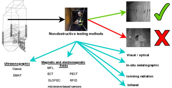
3. Non-Destructive Testing Methods for Fire-Side Corrosion Testing

Non-destructive testing methods (NDT) pertain to non-invasive measurement techniques that allow observers both to study the structure of the construction material and to take quantitative measurement of certain characteristics of the sample studied, for example, of the material thickness. As opposed to destructive testing methods, NDT serves to assess the material’s state without causing damage to the sample studied [69,70].
The NDT methods are used in many industrial fields as well as in nearly every stage of the manufacturing processes for a wide range of products [71,72]. They play a crucial role in ensuring low operating costs, security, and reliability of the whole industrial plant’s functioning. The techniques of non-destructive weld testing are widely used in many industrial fields, including in energy economics as well [73].
Ultrasonographic techniques, as well as the ones using eddy currents, usually exploit small surface probes, which restrict the whole area only to control a tiny bit of the boiler water wall. Moreover, methods using, for example, ionizing radiation and infrared radiation are also being developed.
One of the interesting techniques is in situ metallographic testing, which can be performed during periodic boiler inspections [74]. The method gives additional knowledge regarding the structural changes that occurred in the inspected sections during the exploitation of the boiler. However, it should be noted that such inspections should be performed by well-skilled staff to avoid misinterpretation of the metallographic data [74]. The time and resources needed for advanced diagnostic methods could be saved by initial identification of areas particularly exposed to high corrosion rates, using simple methods.

3.1. Ultrasonographic Methods

Ultrasonographic methods utilize phenomena that result from differences pertaining to the speed of mechanical vibration movement in the materials studied and their surroundings [70,75,76]. The differences trigger the reflection of waves at the media boundaries. The ultrasonographic measurements are realized by sending an ultrasonic impulse to the sample studied. The impulse bounces off the sample edge, comes back to the receptive head and then is presented to the operator. By measuring the reflected wave movement times and by knowing the speed with which the wave moves in a given medium, it is possible to estimate the thickness of the measured sample as well as the localization of the potential unevenness and defect in its structure.
The ultrasonographic technique is of two types:
  • the classic one, which uses the transmitter head generating vibrations;
  • the EMAT Method, in which the mechanical vibrations are evoked in the material studied.
In the first method, one head works as a transmitter, the second one as a receiver. The ultrasonic wave is most frequently generated and converted into electric impulses by means of the piezoelectric phenomenon. Techniques of various technological advancement levels can be distinguished here; however, the classic method (manual measurement with the use of light and hand-held measuring devices) is of the utmost importance in boiler tubes studies.
The classic method requires the appropriate preparation of the sample studied—that is, cleansing its surface as well as using the surface, which transmits the transmitter head vibrations to the sample studied. As for the studies of the boiler tubes’ thickness, they refer to the necessity of the appropriate preparation of the tube surface where the measuring head is located—that is, the deposit has to be removed, and the surface is expected to be polished (Figure 4).
The electromagnetic acoustic transducer method (EMAT) assumes the actuation of vibrations being studied by using the magnetic field. The vibrations inside the sample studied are actuated through the overlapping of two kinds of magnetic fields: constant and variable. These are incited by means of the winding powered by a generator. The material thickness measurement itself is conducted in a similar way to that in which the classic ultrasonic method with the piezoelectric head is conducted. The measurement is carried out using a special head with a transducer not requiring direct contact with the tested material; therefore, there is no need for mechanical removal of the deposit (oxide layer on the fire-side of the water wall or superheater tubes), and measurements can be carried out very quickly without the need for a liquid couplant (as is the case with the ultrasonic method) [70,77]. Such a diagnostic system is suitable for quick wall thickness measurements in power boilers because it enables a detailed examination of the entire evaporator surface and obtains a clear visualization of the control results (color maps).
There are solutions for carrying out the inspection of large surfaces operating at high temperatures [78]. However, measurements of the wall tubes’ thickness are still carried out during the boiler outages because cleaning of the surface is usually necessary before the inspection inside the furnace chamber (especially during biomass combustion, which is accompanied by increased fouling of the heating surface).
However, the automation of measurements (use of robots) would be beneficial, as it would allow measurements to start earlier and reduce the time of the entire diagnostic process.
Undoubtedly, the EMAT Method, in comparison to the classic ultrasonic method, boasts, as its greatest advantage, the possibility of contactless measurement as well as less sensitivity to the state of the surface of the sample studied. This method, nevertheless, has some limitations. One of them is the accuracy of the measurement. Another is the influence of the accuracy of the distance of the head from the test object, and the effect of chemical composition and structure of ash deposits on the signal disturbance [79].

3.2. Methods Employing the Magnetic and Electromagnetic Fields

Because of the possibility of using the study materials utilized in the construction of industrial-scale boilers, one may apply two, out of many, methods of measurement employing magnetic and electromagnetic fields: the magnetic flux leakage method (MFL) and the saturated low-frequency eddy current method (SLOFEC).
The MFL method employs the magnetization of the material studied to the saturation level as well as the measurement of magnetic field corona in places in which material losses and other anomalies are located [71,72,75]. Detecting defects by means of this technique has been known for a long time; new studies concerning this issue refer to methods of establishing the structure of detected defects. The constant magnetic field applied to the material studied is generated by an adequately strong magnet or electromagnet constituting an element of the measuring probe. The field closes inside the sample studied and should trigger saturation of the sample. In the places where losses, material defects, or contractions are present, the magnetic field corona occurs, which is captured by the measuring probe. In one of the recommended solutions, detecting corrosion inside the tubes constitutes the original function of the measuring device. Prior to the test proper, calibration tests are necessary, whose task is to adjust the measurement system to the specifics of the tested object. In these studies, various methods of simulation of defects characteristic of the material studied are employed. High-resolution devices using the MFL Method gather the data roughly every 2 mm along the tube axis. The measurements are processed by the specialized software, which, on the basis of the whole set of data received, assesses the present state and makes a prediction concerning the corrosion progress. The measurement accuracy constitutes the limitation of the method—the material losses can indeed be identified but without the information on which side of the sample studied the loss is located.
The SLOFEC Method uses eddy current along with the constant magnetic field [80]. The classic method employing eddy current is not quite suitable for ferromagnetic materials studies because of the low ability of the current to deeply penetrate materials of this kind. Applying the constant magnetic field to the sample studied causes improvement of the eddy current penetration depth. In the case of a defect, the magnetic field lines have a higher density in the remaining wall thickness where the fault is located. This, as a consequence, changes the medium magnetic permeability and changes the arrangement of the eddy current field lines. Alterations in the arrangement of the eddy current field lines undergo analysis in reference to calibrations with regards to differences in amplitude and the signal phase. The possibility of observation of the phase, amplitude, and shape of the received return signal in the SLOFEC Method allows observers to assess the tube wall thickness loss and distinguishing defects at both sides of the wall [80]. In addition, the SLOFEC Method is not an absolute wall thickness measurement technique, and calibration by a comparison technique, like the ultrasonographic method, is required. Although some similarity in using the magnetic field between the SLOFEC (the constant and variable magnetic field) and EMAT methods can be observed, a fundamental difference between the two exists, too. In the EMAT method, the issue under investigation is the signal resulting from mechanical vibrations in the sample studied. On the other hand, in the SLOFEC method, the induced current is observed.
Another non-contact inspection method that could be used for the purpose of the fire-side corrosion method is eddy current testing (ECT). The method can potentially be used for measuring the wall thickness through insulation and cladding [81]. Pulsed eddy current (PEC) testing is still a relatively new technique used for the inspection of electrically conducting and ferrous materials with corrosion under insulation; it provides considerably more defect information when compared to conventional eddy current techniques due to the use of an excitation pulse that contains broadband frequencies [82]. Pulsed eddy current testing (PECT) uses broadband excitation for sufficient electromagnetic penetration into test objects [81,83]. The PECT signal changes over time along with the penetration of eddy current, and therefore it might be possible to characterize a test object by depth from the analysis of the time-varying signal. The short duty cycle pulses consume lower power in comparison to those of its sinusoidal counterpart. With the same large excitation current, higher excitation pulses can be employed to strengthen induced eddy currents. Overall, the PECT method can be applied to wall-thinning measurement when the pipe wall and cladding sheet’s properties are fully understood. It is possible to apply this approach to other insulated or difficult-to-access test objects, where no contact with the probe is required [81]. Other methods, such as RFID (radio frequency identification) [75], as well as microwave-based sensors [75,84], have attracted interest as novel diagnostic techniques for online monitoring of structural materials’ integrity in the process industry, especially in the context of the development of so-called industry 4.0 [75].

3.3. Methods Employing Ionizing Radiation

Utilizing ionizing radiation may present another method of tube thickness alteration analysis. In this case, however, the tube must be located between the source and receiver of radiation, the latter of which constitutes a specialized scintillator-multiplier phototube system. The electronics in this construction consist of a CCD camera equivalent. In addition, software analyzing the received radiograph results plays a crucial role in the measuring system.
An image from the camera is sent to a computer, where it undergoes an analysis aimed at establishing the thickness of the wall of the x-rayed tube. Methods utilizing ionizing radiation are, in practice, used for tube wall thickness measurement. However, they require synchronized radiation source placement and a receiver head at both sides of the analyzed tube. They detect corrosion and erosion defects both sides on the outer and inner tube surface, as well as the insulated and deposit-covered tubes [85,86,87]. In the case of field studies in boilers with airtight screens, this may cause some difficulties, especially when additional angular exposure is required. This method type, nevertheless, allows for the measurement process automatization with minimal costs destined for the preparation of the surfaces for analysis.

3.4. Infrared Radiation-Based Methods

Methods employing infrared radiation concern observation of the heat corona of the material studied heated by the local heat impulse. The observation is assisted with the camera working in the infrared mode. The pace at which the material regions with different thicknesses give up the heat varies. This allows for distinguishing and detecting the material regions. Moreover, on the basis of temperature change dynamics, one can roughly assess the material thickness changes as well as other defects influencing the way heat is conducted in the material. In this method, the infrared camera moves (as one device) with a linear heat source in such a way as to situate in the camera view the material region before and after heating it. The temperature recorded from the unheated region contains information about the initial temperature schema in the sample studied. One of the advantages this method offers is the easiness with which the measuring process is automated as well as the possibility to gain the map of the thickness of large-surface screens after the scan process is over. Unfortunately, the results are subordinate to the material heat capacity as well as heat conductivity both of the tube material and the deposited layer, the latter one being, in most cases, heterogeneous. That is why it is necessary, prior to the analysis, to carefully cleanse the surface [88]. An example of using this measurement technique for the study of the boiler screen is the Line Scanning Thermography System (LST) produced by the Mistras Company [88].

3.5. Other Methods

Other methods of non-destructive testing could likely find their way to corrosion detecting systems in boilers. Al-Mayouf and Al-Shalwi [89] investigated a simple galvanic sensor that was useful for determining the start of iron corrosion under situations similar to those used for separating layers of iron oxide magnetite from the steam boiler with the 5% HCL solution at 60 °C. The time at which the inclusion of corrosion inhibitors is needed to safeguard the base metal can be signaled by this sensor [89]. The fiber brag grating (FBG) system employs the use of photoacoustic sensors [75]. With a photoacoustic sensor, two types of ultrasonic waves are generated: body waves (i.e., p-waves and s-waves) and surface waves (fundamental mode of Rayleigh waves), which have higher amplitude and are more sensitive to corrosion [75]. Recently, PARC Company has developed a technique to allow optical fiber sensors to detect the wavelength deviation with a 50 femtometer resolution [75]. The idea is to use a distributed array of high precision photosensors. Brillouin distributed fiber is another sensor used for corrosion monitoring since it measures the strain very precisely [75].

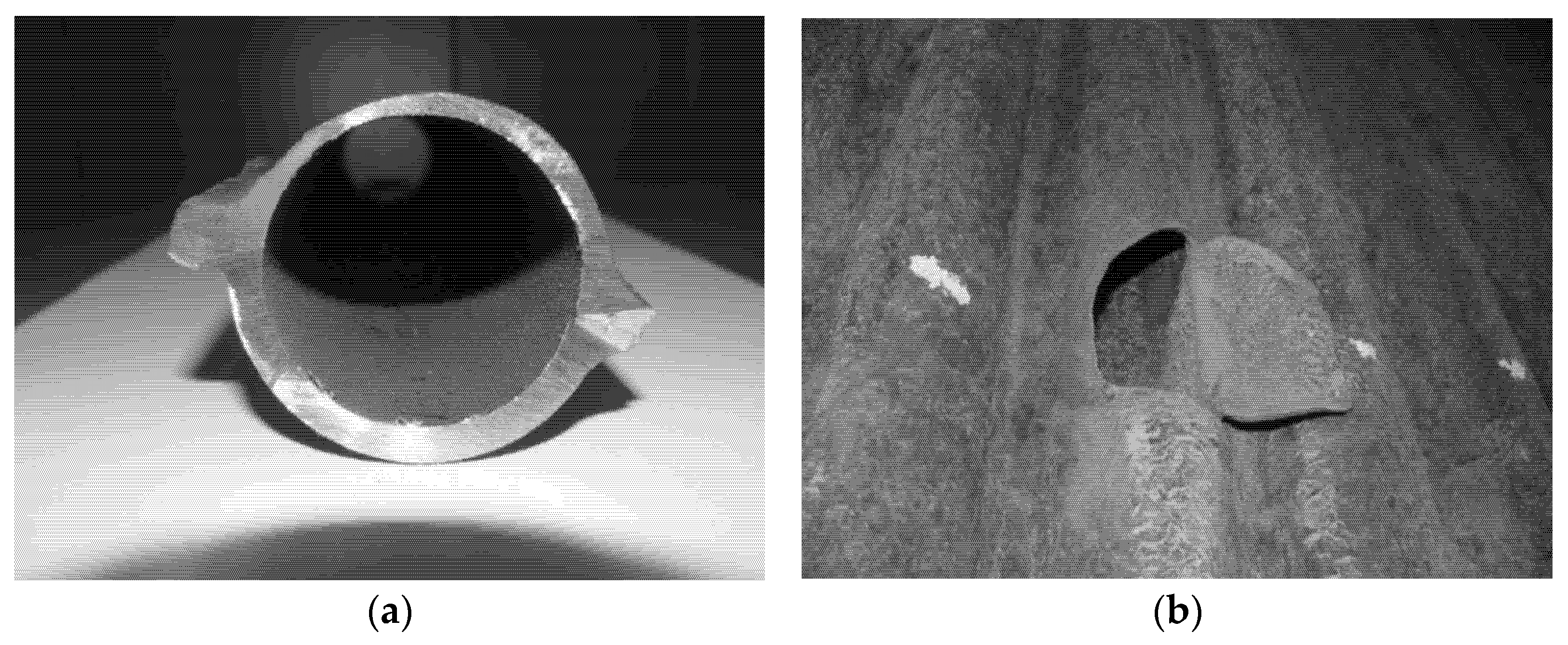
4. Available Automatic Systems with Visual Data Processing

In order to determine the boiler tubes’ thickness, it is necessary to put scaffolds in the boiler and to carefully cleanse the surface with a water stream. It is essential to study an appropriately large screen surface region in as short a time as possible. Thus, it seems profitable to automate such a study by utilizing special robots intended to relocate measuring probes. Vakhguelt et al. [76] reported a conceptual design of a climbing robot for corrosion measurements in power plant scale boilers, using EMA sensors [76].
The Bhabha Atomic Research Centre (BARC) is one of the companies that has attempted to construct such a robot, which was intended for vertical movement along the boiler wall tubes. The robot was adapted to relocate the EMAT measuring head and was able to carry weight amounting to 10 kg at speed up to 120 mm/s [90]. Such a solution allows for scanning the region of a large wall, detecting all of the critical wall tubes regions, and, subsequently, making meticulous measurements of the thickness of the tubes by means of the classic ultrasonic method in the very places that were detected.
The Vertiscan™ System by the Russell NDE Systems Company from Canada uses, on the other hand, a magnetic robot—TubeCAT™—capable of self-moving along the vertical tubes of the boiler. The robot, which uses the electromagnetic measurement method, has a scanner (known as E-PIT) able to analyze five tubes at a time [91]. The system is calibrated by using ultrasonic measurements.
The Alstom Company has been working for a few years on the development of mobile robots. It is in possession of a few solutions which may be successfully used in the boiler combustion chamber conditions playing the role of an automatized platform, for example, in non-destructive studies (ultrasonography, eddy current, thermography, and radiation measurements), in the visual inspection of the boiler (a video camera, 3D scanning), and in the heating surface cleansing [92].
Using the visual systems may constitute technique supplementation, complementing the tube thickness diagnostics, and may aid the initial evaluation of the heating boilers’ surface state. Systems of this kind utilize the tube surfaces photographs taken in visible light. A prototype of such a computer vision system intended for evaluating the state of the boiler evaporators’ surface was designed in the Department of Automation, Mechatronics and Control Systems at the Wrocław University of Science and Technology.
The system equipment consists of a digital camera, LED illuminator, and devices that aid in directing towards and indicating the current position in which the camera was located while taking a photograph. The device may be moved by an operator (Figure 5), although plans exist for the construction of some sort of mobile platform capable of moving along the boiler walls by itself (as a robot).
The system software performs the photograph archiving and registers the data indicating the position as well as further analysis of what is visible in the photographs [93]. The information is saved in the database, which enables one to visualize the whole wall or a selected fragment bigger than a single photograph in the form of a photomosaic (Figure 6). The possible use of machine vision systems depends on what has been photographed and what kind of functions are implemented in the software. In the case of self-propelled devices, the software will also aid the device movement control.
The field of application of vision systems is determined by what is intended for photographing as well as the functions performed by the software that analyzes the collected photographs. One of the possible applications of the vision methods is the analysis of deposits that have accumulated on the surface of the tube. In such a situation, the photographs are taken prior to getting rid of the deposit from the evaporator surface. By comparing photographs of selected regions that were taken in various time periods, one may, for example, assess the effectiveness of deposit blower work and the influence of variable fuel properties on deposit formation.
After partial ash deposit removal, it is possible to search out, by means of picture analysis methods, the places where the deposit underwent melting. Drawing conclusions about the state of the boiler walls on the basis of the appearance of the deposit accumulated on the walls is risky and requires the collection of the data from manifold measurements as well as search for correlations by means of mathematical statistics methods. In the designed software, the possibility of carrying out such analyses was provided.
The vision analysis may also concern the surface of the metal of which the tubes have been made; nonetheless, it requires, in the beginning, the removal of the deposit that has accumulated on this surface. The photographs taken in such a situation may be analyzed through the picture detection methods, which are color irregularity measurement oriented. Based on this, one may draw conclusions about the corrosion pitting on the metal. Generally, images are obtained in the form of RGB components (with the possible Bayer matrix at the sensor level). For this kind of analysis, a form of hue and saturation, the HSV value is considered to be better. The size of the color space is roughly the same since we also have three parameters. The hue parameter controls color but in the form of a color wheel; therefore, similar values have similar colors (if we accept that 0 and 255 are close). This allows for much simpler processing methods.
Descriptions of the measuring devices offered by various producers usually contain information about the necessity to calibrate the device to particular applications. This requirement concerns carrying out the test measurements, processing the collected data, and, on the basis thereof, setting the parameters used during the measurement proper. Data collected during the measurements is also compared to the model measurements database, and, on this basis, one makes the final evaluation of the interpretation of the collected material.
Generally, the received measurement data constitutes data emerging as the sum of responses of fragments studied from many samples. It causes some difficulties in determining the unambiguous location and size of the detected defect in the structure of the material studied. Usually, the ultrasonographic study is exemplified as the model method of tube thickness measurement.

5. Conclusions

As far as the matter of the measurement methods used in not-destroying-metals testing is concerned, one should focus on two issues:
  • a physical phenomenon used for collecting measurement data;
  • processing the collected data by means of computer techniques.
The methods that have the best chance of being widely used are those that allow for relatively meticulous determination of the tube walls’ thickness without the need to build a scaffold in the boiler firebox. The experience gained so far with the automation of wall tube thickness measurement using the EMAT method shows its great potential and the possibility of making quick measurements without time-consuming surface cleaning, unlike the most commonly used method today—the ultrasonic method. If robots carrying the measuring head are used (automatized measurement), it will be possible to test the entire wall without the need to erect scaffolding.
Additionally, the vision methods will serve as aids; they will, in turn, be aided by the appropriate computer software intended for processing and analyzing pictures. In this case, it will be possible to use drones to take photos of the water wall surfaces in the boiler.
Non-destructive testing methods for fire-side corrosion testing are well proven for the corrosion testing of water walls of the boiler. Straightforward utilization for inspection of the superheaters might prove challenging due to difficult access. Further work is required on this topic.

Author Contributions

Conceptualization: T.H., H.P.-K., W.R. and J.W.; investigation: T.H., H.P.-K., W.R., J.W., K.M., V. and Ł.N.; resources, T.H. and H.P.-K.; writing—original draft preparation, T.H., A.A., H.P.-K., W.R., J.W., K.M., V. and Ł.N.; writing—review and editing, T.H., H.P.-K., A.A., K.M. and Ł.N.; visualization, T.H., K.M. and Ł.N.; supervision, T.H. and H.P.-K.; project administration, T.H. and H.P.-K.; funding acquisition, T.H. and H.P.-K. All authors have read and agreed to the published version of the manuscript.

Funding

Support from the project “Corrosion and Emission Reduction of Utility Boilers through Intelligent Systems” CERUBIS (RFCR-CT-2014-00008), funded by the European Research Fund for Coal and Steel, is gratefully acknowledged.

Institutional Review Board Statement

Not applicable.

Informed Consent Statement

Not applicable.

Data Availability Statement

Not applicable.

Conflicts of Interest

The authors declare no conflict of interest.

References

  1. Pronobis, M. Evaluation of the influence of biomass co-combustion on boiler furnace slagging by means of fusibility correlations. Biomass Bioenergy 2005, 28, 375–383. [Google Scholar] [CrossRef]
  2. Pronobis, M. Modernizacja Kotłów Energetycznych; WNT: Warszawa, Poland, 2009; ISBN 9788379261352. [Google Scholar]
  3. Hein, K.R.G. Operational Problems, Trace Emissions and By-Product Management for Industrial Biomass Co-Combustion; CORDIS: Brussels, Belgium, 2000. [Google Scholar]
  4. Harb, J.; Smith, E. Fireside corrosion in pc-fired boilers. Prog. Energy Combust. Sci. 1990, 16, 169–190. [Google Scholar] [CrossRef]
  5. Li, G.; Li, S.; Huang, Q.; Yao, Q. Fine particulate formation and ash deposition during pulverized coal combustion of high-sodium lignite in a down-fired furnace. Fuel 2015, 143, 430–437. [Google Scholar] [CrossRef]
  6. Zheng, S.; Zeng, X.; Qi, C.; Zhou, H. Mathematical modeling and experimental validation of ash deposition in a pulverized-coal boiler. Appl. Eng. 2017, 110, 720–729. [Google Scholar] [CrossRef]
  7. Wang, X.; Xu, Z.; Wei, B.; Zhang, L.; Tan, H.; Yang, T.; Mikulčić, H.; Duić, N. The ash deposition mechanism in boilers burning Zhundong coal with high contents of sodium and calcium: A study from ash evaporating to condensing. Appl. Eng. 2015, 80, 150–159. [Google Scholar] [CrossRef] [Green Version]
  8. Gao, Q.; Li, S.; Yang, M.; Biswas, P.; Yao, Q. Measurement and numerical simulation of ultrafine particle size distribution in the early stage of high-sodium lignite combustion. Proc. Combust. Inst. 2017, 36, 2083–2090. [Google Scholar] [CrossRef]
  9. Golański, G.; Lachowicz, M.M. Failure cause analysis for the suspension element of boiler superheater. Eng. Fail. Anal. 2019, 105, 490–495. [Google Scholar] [CrossRef]
  10. Pawlak-Kruczek, H.; Niedźwiecki, Ł.; Ostrycharczyk, M.; Czerep, M.; Plutecki, Z. Potential and methods for increasing the flexibility and efficiency of the lignite fired power unit, using integrated lignite drying. Energy 2019, 181, 1142–1151. [Google Scholar] [CrossRef]
  11. Duarte, C.A.; Espejo, E.; Martinez, J.C. Failure analysis of the wall tubes of a water-tube boiler. Eng. Fail. Anal. 2017, 79, 704–713. [Google Scholar] [CrossRef]
  12. Sims, R. The Brilliance of Bioenergy: In Business and Practice; Earthscan Publications Ltd.: London, UK, 2002; ISBN 978-1902916286. [Google Scholar]
  13. Sher, F.; Iqbal, S.Z.; Liu, H.; Imran, M.; Snape, C.E. Thermal and kinetic analysis of diverse biomass fuels under different reaction environment: A way forward to renewable energy sources. Energy Convers. Manag. 2020, 203, 112266. [Google Scholar] [CrossRef]
  14. Tzelepi, V.; Zeneli, M.; Kourkoumpas, D.S.; Karampinis, E.; Gypakis, A.; Nikolopoulos, N.; Grammelis, P. Biomass availability in europe as an alternative fuel for full conversion of lignite power plants: A critical review. Energies 2020, 13, 3390. [Google Scholar] [CrossRef]
  15. Jewiarz, M.; Wróbel, M.; Mudryk, K.; Szufa, S. Impact of the drying temperature and grinding technique on biomass grindability. Energies 2020, 13, 3392. [Google Scholar] [CrossRef]
  16. Romanowska-Duda, Z.; Piotrowski, K.; Wolska, B.; Debowski, M.; Zielinski, M.; Dziugan, P.; Szufa, S. Stimulating Effect of Ash from Sorghum on the Growth of Lemnaceae—A New Source of Energy Biomass; Springer International Publishing: 2020; pp. 341–349, ISBN 9783030138882. Available online: https://link.springer.com/chapter/10.1007/978-3-030-13888-2_34 (accessed on 1 September 2021).
  17. Szufa, S.; Wielgosiński, G.; Piersa, P.; Czerwińska, J.; Dzikuć, M.; Adrian, Ł.; Lewandowska, W.; Marczak, M. Torrefaction of Straw from Oats and Maize for Use as a Fuel and Additive to Organic Fertilizers—TGA Analysis, Kinetics as Products for Agricultural Purposes. Energies 2020, 13, 2064. [Google Scholar] [CrossRef] [Green Version]
  18. Luo, H.; Lu, Z.; Jensen, P.A.; Glarborg, P.; Lin, W.; Dam-Johansen, K.; Wu, H. Experimental and modelling study on the influence of wood type, density, water content, and temperature on wood devolatilization. Fuel 2020, 260, 116410. [Google Scholar] [CrossRef]
  19. Tran, K.Q.; Werle, S.; Trinh, T.T.; Magdziarz, A.; Sobek, S.; Pogrzeba, M. Fuel characterization and thermal degradation kinetics of biomass from phytoremediation plants. Biomass Bioenergy 2020, 134, 105469. [Google Scholar] [CrossRef]
  20. Polesek-Karczewska, S.; Turzyński, T.; Kardaś, D.; Heda, Ł. Front velocity in the combustion of blends of poultry litter with straw. Fuel Process. Technol. 2018, 176, 307–315. [Google Scholar] [CrossRef]
  21. Shao, Y.; Wang, J.; Preto, F.; Zhu, J.; Xu, C. Ash deposition in biomass combustion or co-firing for power/heat generation. Energies 2012, 5, 5171–5189. [Google Scholar] [CrossRef]
  22. Magdziarz, A.; Gajek, M.; Nowak-Woźny, D.; Wilk, M. Mineral phase transformation of biomass ashes—Experimental and thermochemical calculations. Renew. Energy 2018, 128, 446–459. [Google Scholar] [CrossRef]
  23. Zuwała, J.; Lasek, J. Co-combustion of low-rank coals with biomass. In Low-Rank Coals for Power Generation, Fuel and Chemical Production; Woodhead Publishing: Sawston, UK, 2017; pp. 125–158. ISBN 9780081008959. [Google Scholar]
  24. Mlonka-Mędrala, A.; Magdziarz, A.; Gajek, M.; Nowińska, K.; Nowak, W. Alkali metals association in biomass and their impact on ash melting behaviour. Fuel 2020, 261, 116421. [Google Scholar] [CrossRef]
  25. Mlonka-Mędrala, A.; Magdziarz, A.; Dziok, T.; Sieradzka, M.; Nowak, W. Laboratory studies on the influence of biomass particle size on pyrolysis and combustion using TG GC/MS. Fuel 2019, 252, 635–645. [Google Scholar] [CrossRef]
  26. Phongphiphat, A.; Ryu, C.; Yang, Y.B.; Finney, K.N.; Leyland, A.; Sharifi, V.N.; Swithenbank, J. Investigation into high-temperature corrosion in a large-scale municipal waste-to-energy plant. Corros. Sci. 2010, 52, 3861–3874. [Google Scholar] [CrossRef] [Green Version]
  27. Viklund, P.; Hjörnhede, A.; Henderson, P.; Stålenheim, A.; Pettersson, R. Corrosion of superheater materials in a waste-to-energy plant. Fuel Process. Technol. 2013, 105, 106–112. [Google Scholar] [CrossRef]
  28. Wan, W.; Engvall, K.; Yang, W. Model investigation of condensation behaviors of alkalis during syngas treatment of pressurized biomass gasification. Chem. Eng. Process.-Process. Intensif. 2018, 129, 28–36. [Google Scholar] [CrossRef]
  29. Mlonka-Mędrala, A.; Gołombek, K.; Buk, P.; Cieślik, E.; Nowak, W. The influence of KCl on biomass ash melting behaviour and high-temperature corrosion of low-alloy steel. Energy 2019, 188, 116062. [Google Scholar] [CrossRef]
  30. Sandhi, K.K.; Szpunar, J. Analysis of Corrosion of Hastelloy-N, Alloy X750, SS316 and SS304 in Molten Salt High-Temperature Environment. Energies 2021, 14, 543. [Google Scholar] [CrossRef]
  31. Kofstad, P. High Temperature Corrosion; Elsevier Applied Science: London, UK; New York, NY, USA, 1988; ISBN 1-85166-154-9. [Google Scholar]
  32. Von Bohnstein, M.; Yildiz, C.; Frigge, L.; Ströhle, J.; Epple, B. Simulation study of the formation of corrosive gases in coal combustion in an entrained flow reactor. Energies 2020, 13, 4523. [Google Scholar] [CrossRef]
  33. Tesfaye, F.; Lindberg, D.; Moroz, M.; Hupa, L. Investigation of the K-Mg-Ca Sulfate System as Part of Monitoring Problematic Phase Formations in Renewable-Energy Power Plants. Energies 2020, 13, 5366. [Google Scholar] [CrossRef]
  34. Sweden Linnæus University (Project Leader); Estonia Tallinn University of Technology; Greece CERTH; Italy IVALSA-Ireland Tipperary Energy Agency. The Bioenergy System Planners Handbook-BISYPLAN. Available online: http://bisyplan.bioenarea.eu/html-files-en/ (accessed on 24 July 2016).
  35. Basu, P. Combustion and Gasification in Fluidized Beds; CRC Press: Boca Raton, FL, USA, 2006; ISBN 9780849333965. [Google Scholar]
  36. Kulokas, M.; Praspaliauskas, M.; Pedišius, N. Investigation of Buckwheat Hulls as Additives in the Production of Solid Biomass Fuel from Straw. Energies 2021, 14, 265. [Google Scholar] [CrossRef]
  37. Van Loo, S.; Koppejan, J. The Handbook of Biomass Combustion and Co-Firing; Earthscan: London, UK, 2008; ISBN 978-1-84407-249-1. [Google Scholar]
  38. Keipi, T.; Tolvanen, H.; Kokko, L.; Raiko, R. The effect of torrefaction on the chlorine content and heating value of eight woody biomass samples. Biomass Bioenergy 2014, 66, 232–239. [Google Scholar] [CrossRef]
  39. Reza, M.T.; Yan, W.; Uddin, M.H.; Lynam, J.G.; Hoekman, S.K.; Coronella, C.J.; Vásquez, V.R. Reaction kinetics of hydrothermal carbonization of loblolly pine. Bioresour. Technol. 2013, 139, 161–169. [Google Scholar] [CrossRef]
  40. Kambo, H.S.; Dutta, A. Comparative evaluation of torrefaction and hydrothermal carbonization of lignocellulosic biomass for the production of solid biofuel. Energy Convers. Manag. 2015, 105, 746–755. [Google Scholar] [CrossRef]
  41. Śliz, M.; Wilk, M. A comprehensive investigation of hydrothermal carbonization: Energy potential of hydrochar derived from Virginia mallow. Renew. Energy 2020, 156, 942–950. [Google Scholar] [CrossRef]
  42. Wilk, M.; Magdziarz, A.; Kalemba-Rec, I.; Szymańska-Chargot, M. Upgrading of green waste into carbon-rich solid biofuel by hydrothermal carbonization: The effect of process parameters on hydrochar derived from acacia. Energy 2020, 202, 117717. [Google Scholar] [CrossRef]
  43. Smith, A.M.; Ekpo, U.; Ross, A.B. The influence of pH on the combustion properties of bio-coal following hydrothermal treatment of swine manure. Energies 2020, 13, 331. [Google Scholar] [CrossRef] [Green Version]
  44. Aragón-Briceño, C.I.; Grasham, O.; Ross, A.B.; Dupont, V.; Camargo-Valero, M.A. Hydrothermal carbonization of sewage digestate at wastewater treatment works: Influence of solid loading on characteristics of hydrochar, process water and plant energetics. Renew. Energy 2020, 157, 959–973. [Google Scholar] [CrossRef]
  45. Aragón-Briceño, C.I.; Ross, A.B.; Camargo-Valero, M.A. Mass and energy integration study of hydrothermal carbonization with anaerobic digestion of sewage sludge. Renew. Energy 2021, 167, 473–483. [Google Scholar] [CrossRef]
  46. Surup, G.R.; Leahy, J.J.; Timko, M.T.; Trubetskaya, A. Hydrothermal carbonization of olive wastes to produce renewable, binder-free pellets for use as metallurgical reducing agents. Renew. Energy 2020, 155, 347–357. [Google Scholar] [CrossRef]
  47. Ameen, M.; Zamri, N.M.; May, S.T.; Azizan, M.T.; Aqsha, A.; Sabzoi, N.; Sher, F. Effect of acid catalysts on hydrothermal carbonization of Malaysian oil palm residues (leaves, fronds, and shells) for hydrochar production. Biomass Convers. Biorefin. 2021. [Google Scholar] [CrossRef]
  48. Atallah, E.; Zeaiter, J.; Ahmad, M.N.; Leahy, J.J.; Kwapinski, W. Hydrothermal carbonization of spent mushroom compost waste compared against torrefaction and pyrolysis. Fuel Process. Technol. 2021, 216, 106795. [Google Scholar] [CrossRef]
  49. Zhang, H.; Li, J.; Yang, X.; Guo, S.; Zhan, H.; Zhang, Y.; Fang, Y. Influence of coal ash on potassium retention and ash melting characteristics during gasification of corn stalk coke. Bioresour. Technol. 2018, 270, 416–421. [Google Scholar] [CrossRef]
  50. Elled, A.L.; Davidsson, K.O.; Åmand, L.E. Sewage sludge as a deposit inhibitor when co-fired with high potassium fuels. Biomass Bioenergy 2010, 34, 1546–1554. [Google Scholar] [CrossRef] [Green Version]
  51. Aho, M.; Yrjas, P.; Taipale, R.; Hupa, M.; Silvennoinen, J. Reduction of superheater corrosion by co-firing risky biomass with sewage sludge. Fuel 2010, 89, 2376–2386. [Google Scholar] [CrossRef]
  52. Kassman, H.; Pettersson, J.; Steenari, B.M.; Åmand, L.E. Two strategies to reduce gaseous KCl and chlorine in deposits during biomass combustion—Injection of ammonium sulphate and co-combustion with peat. Fuel Process. Technol. 2013, 105, 170–180. [Google Scholar] [CrossRef]
  53. Niu, Y.; Tan, H.; Hui, S. Ash-related issues during biomass combustion: Alkali-induced slagging, silicate melt-induced slagging (ash fusion), agglomeration, corrosion, ash utilization, and related countermeasures. Prog. Energy Combust. Sci. 2016, 52, 1–61. [Google Scholar] [CrossRef]
  54. Wang, L.; Skreiberg, Ø.; Becidan, M.; Li, H. Investigation of rye straw ash sintering characteristics and the effect of additives. Appl. Energy 2016, 162, 1195–1204. [Google Scholar] [CrossRef]
  55. Antunes, R.A.; de Oliveira, M.C.L. Corrosion in biomass combustion: A materials selection analysis and its interaction with corrosion mechanisms and mitigation strategies. Corros. Sci. 2013, 76, 6–26. [Google Scholar] [CrossRef]
  56. Naganuma, H.; Ikeda, N.; Ito, T.; Satake, H.; Matsuura, M.; Ueki, Y.; Yoshiie, R.; Naruse, I. Control of ash deposition in solid fuel fired boiler. Fuel Process. Technol. 2013, 105, 77–81. [Google Scholar] [CrossRef]
  57. Pophali, A.; Emami, B.; Bussmann, M.; Tran, H. Studies on sootblower jet dynamics and ash deposit removal in industrial boilers. Fuel Process. Technol. 2013, 105, 69–76. [Google Scholar] [CrossRef]
  58. Kruczek, H. Effect of staged combustion in PC boilers on rate of fire-side corrosion. In Proceedings of the 7th European Conference on Industrial Furnaces and Boilers, Porto, Portugal, 18–21 April 2006. [Google Scholar]
  59. Hardy, T.; Kakietek, S.; Janda, T. A tool for on-line control of high-temperature corrosion hazard in steam boilers. Arch. Combust. 2017, 37, 107–118. [Google Scholar]
  60. Pronobis, M.; Litka, R. Rate of corrosion of waterwalls in supercritical pulverised fuel boilers. Chem. Process. Eng.-Inz. Chem. I Proces. 2012, 33, 263–277. [Google Scholar] [CrossRef] [Green Version]
  61. Wejkowski, R.; Kalisz, S.; Hardy, T.; Sarapata, B.; Kubiczek, H.; Janda, T. The control of high temperature corrosion phenomenon in boundary layer using different measurement methods. In Modern Energy Technologies, Systems and Units; Taler, J., Ed.; Publishing House of Kraków University of Technology: Krakow, Poland, 2013; pp. 289–300. [Google Scholar]
  62. Modlinski, N.J. Computational modelling of a tangentially fired boiler with deposit formation phenomena. Chem. Process. Eng.-Inz. Chem. I Proces. 2014, 35, 361–368. [Google Scholar] [CrossRef] [Green Version]
  63. Weber, R.; Mancini, M.; Schaffel-Mancini, N.; Kupka, T. On predicting the ash behaviour using Computational Fluid Dynamics. Fuel Process. Technol. 2013, 105, 113–128. [Google Scholar] [CrossRef]
  64. Davis, K.A.; Linjewile, T.M.; Valentine, J.; Swensen, D.; Shino, D.; Letcavits, J.J.; Sheidler, R.; Cox, W.M.; Carr, R.N.; Harding, N.S. A multi-point corrosion monitoring system applied in a 1300 MW coal-fired boiler. Anti-Corros. Methods Mater. 2004, 51, 321–330. [Google Scholar] [CrossRef]
  65. Hardy, T.; Modlinski, N. Development of Prognostic Tool for High-temperature Corrosion Risk Assessment in Pulverised Coal Boilers Based on the Waterwalls Boundary Layer Monitoring System and CFD Simulations. Energy Procedia 2017, 105, 1833–1838. [Google Scholar] [CrossRef]
  66. Modlinski, N.; Hardy, T. Development of high-temperature corrosion risk monitoring system in pulverized coal boilers based on reducing conditions identification and CFD simulations. Appl. Energy 2017, 204, 1124–1137. [Google Scholar] [CrossRef]
  67. Gruber, T.; Schulze, K.; Scharler, R.; Obernberger, I. Investigation of the corrosion behaviour of 13CrMo4-5 for biomass fired boilers with coupled online corrosion and deposit probe measurements. Fuel 2015, 144, 15–24. [Google Scholar] [CrossRef]
  68. Zhang, Y.; Fang, Y.; Jin, B.; Zhang, Y.; Zhou, C.; Sher, F. Effect of Slot Wall Jet on Combustion Process in a 660 MW Opposed Wall Fired Pulverized Coal Boiler. Int. J. Chem. React. Eng. 2019, 17, 1–13. [Google Scholar] [CrossRef]
  69. Vavilov, V.P.; Burleigh, D.D. Review of pulsed thermal NDT: Physical principles, theory and data processing. NDT E Int. 2015, 73, 28–52. [Google Scholar] [CrossRef]
  70. Vakhguelt, A.; Kapayeva, S.D.; Bergander, M.J. Combination Non-Destructive Test (NDT) Method for Early Damage Detection and Condition Assessment of Boiler Tubes. Procedia Eng. 2017, 188, 125–132. [Google Scholar] [CrossRef]
  71. Ho, M.; El-Borgi, S.; Patil, D.; Song, G. Inspection and monitoring systems subsea pipelines: A review paper. Struct. Health Monit. 2020, 19, 606–645. [Google Scholar] [CrossRef] [Green Version]
  72. Shi, Y.; Zhang, C.; Li, R.; Cai, M.; Jia, G. Theory and application of magnetic flux leakage pipeline detection. Sensors 2015, 15, 31036–31055. [Google Scholar] [CrossRef]
  73. Lu, X.; Liu, G.; Luan, S. The development of the boiler water wall tube inspection. In Proceedings of the 2008 3rd International Conference on Electric Utility Deregulation and Restructuring and Power Technologies, Nanjing, China, 6–9 April 2008; pp. 2415–2420. [Google Scholar] [CrossRef]
  74. Hariyadi, A.; Kis Agustin, H.C.; Wijayanti, I.D. Metallography Investigation of Dry Corrosion Boiler Tube. Appl. Mech. Mater. 2016, 836, 72–77. [Google Scholar] [CrossRef]
  75. Meribout, M.; Mekid, S.; Kharoua, N.; Khezzar, L. Online monitoring of structural materials integrity in process industry for I4.0: A focus on material loss through erosion and corrosion sensing. Meas. J. Int. Meas. Confed. 2021, 176, 109110. [Google Scholar] [CrossRef]
  76. Vakhguelt, A.; Jo, R.S.; Bergander, M.J. Electromagnetic acoustic boiler tubes inspection with robotic device. Vibroeng. Procedia 2017, 15, 115–118. [Google Scholar] [CrossRef] [Green Version]
  77. Bergander, M.J. EMAT thickness measurement for tubes in coal-fired boilers. Appl. Energy 2003, 74, 439–444. [Google Scholar] [CrossRef]
  78. Kogia, M.; Gan, T.-H.; Balachandran, W.; Livadas, M.; Kappatos, V.; Szabo, I.; Mohimi, A.; Round, A. High Temperature Shear Horizontal Electromagnetic Acoustic Transducer for Guided Wave Inspection. Sensors 2016, 16, 582. [Google Scholar] [CrossRef] [Green Version]
  79. Klepacki, F. Ocena stanu rur kotłowych, których grubość ścianek uległa zmniejszeniu wskutek erozji lub korozji. Energetyka 2005, 886–888. Available online: https://www.pronovum.pl/static/upload/store/Ocena_stanu_rur_kotlowych_ktorych_gruboisc_scianek_ulega_zmniejszeniu_wskutek_erozji_lub_korozji.pdf (accessed on 30 September 2021).
  80. Innospection SLOFEC TM—Fast Corrosion Screening Technique. Available online: http://www.ndttechnologies.com/Brochures/TankScanning/SLOFECTechnique.pdf (accessed on 1 September 2021).
  81. Cheng, W. Pulsed eddy current testing of carbon steel pipes’ wall-thinning through insulation and cladding. J. Nondestruct. Eval. 2012, 31, 215–224. [Google Scholar] [CrossRef]
  82. Fernandez, N.M.; Charlton, P.C.; Granville, R.K. Pulsed Eddy Current CUI Simulation with Coupled Electric Circuit Analysis using Quickfield FEA. e-J. Nondestruct. Test. 2019. Available online: https://www.ndt.net/article/ndtnet/papers/Pulsed-Eddy-Current-CUI-Simulation-with-Coupled-Electric-Circuit-Analysis-using-Quickfield-FEA.pdf (accessed on 30 September 2021).
  83. Cheng, W.; Komura, I. Pulsed Eddy Current Testing of Carbon Steel Pipes’ Wall-thinning. In Proceedings of the 9th International Conference on NDE in Relation to Structural Integrity for Nuclear and Pressurized Components, Seattle, DC, USA, 22–24 May 2012; pp. 336–342. [Google Scholar]
  84. Katagiri, T.; Chen, G.; Yusa, N.; Hashizume, H. Demonstration of detection of the multiple pipe wall thinning defects using microwaves. Meas. J. Int. Meas. Confed. 2021, 175, 109074. [Google Scholar] [CrossRef]
  85. Boateng, A.; Danso, K.A.; Dagadu, C.P.K. Non-Destructive Evaluation Of Corrosion On Insulated Pipe Using Double Wall Radiographic Technique. Chem. Mater. Res. 2013, 3, 73–83. [Google Scholar]
  86. Boateng, A.; Danso, K.A.; Dagadu, C.P.K. Non-Destructive Evaluation Of Corrosion On Insulated Pipe Using Tangential Radiographic Technique. Int. J. Sci. Technol. Res. 2013, 2, 7–13. [Google Scholar]
  87. Edalati, K.; Rastkhah, N.; Kermani, A.; Seiedi, M.; Movafeghi, A. The use of radiography for thickness measurement and corrosion monitoring in pipes. Int. J. Press. Vessel. Pip. 2006, 83, 736–741. [Google Scholar] [CrossRef]
  88. MISTRAS Automated Thickness Measurement Using Line Scanning Thermography (LST)TM. Available online: http://www.mistrasgroup.com/services/company/publications/Line_Scanning_Thermography.pdf (accessed on 1 July 2018).
  89. Al-mayouf, A.M.; Al-shalwi, M.N. Galvanic sensor for detecting corrosion during acid cleaning of magnetite in steam boilers. Metals 2021, 11, 343. [Google Scholar] [CrossRef]
  90. Badodkar, D.N.; Singh, N.K.; Dalal, N.S.; Singh, M. EMAT Integrated with Vertical Climbing Robot for Boiler Tube Inspection. In Proceedings of the National Seminar & Exhibition on Non-Destructive Evaluation, Tiruchirappalli, India, 10–12 December 2009; pp. 32–36. [Google Scholar]
  91. Vajpayee, A.; Russell, D. Automated Condition Assessment of Boiler Water Wall Tubes Using Remote Field Technology. A Revolution Over Traditional and Existing Techniques. In Proceedings of the 10th International Conference of the Slovenian Society for Non-Destructive Testing 2009, Application of Contemporary Non-Destructive Testing in Engineering, Ljubljana, Slovenia, 1–3 September 2009; pp. 523–530. [Google Scholar]
  92. Caprari, G.; Breitenmoser, A.; Fischer, W.; Hürzeler, C.; Tâche, F.; Siegwart, R.; Schoeneich, P.; Rochat, F.; Mondada, F.; Moser, R. Highly compact robots for inspection of power plants. In Proceedings of the 1st International Conference on Applied Robotics for the Power Industry (CARPI), Montreal, QC, Canada, 5–7 October 2010. [Google Scholar] [CrossRef] [Green Version]
  93. Rafajłowicz, E.; Wietrzych, J.; Rafajłowicz, W. A computer vision system for evaluation of high temperature corrosion damages in steam boilers. In Intelligent Systems in Technical and Medical Diagnostics. Advances in Intelligent Systems and Computing; Korbicz, J., Kowal, M., Eds.; Springer: Berlin/Heidelberg, Germany, 2014; Volume 230. [Google Scholar] [CrossRef]
Figure 1. Fouling by KCl in a fixed bed straw boiler (left), with chloride and sulfide corrosion mechanism (right)—adapted, based on [34,35] (SH1 and 2—sections of the superheaters in the boiler).
Energies 14 07132 g001
Figure 2. Miscanthus after wet torrefaction in different process conditions (samples after wet torrefaction in 200 °C, 10 min, water: biomass ratio 12:1): (a) raw samples; (b) samples after 3 h of ashing in the furnace at 850 °C.
Energies 14 07132 g002
Figure 3. Visible darkening of the tube wall and its effect on the boiler OP430 damage: (a) a fragment of corroded pipe, cut-out during the maintenance; (b) evaporator pipe ruptured in the boiler (photo by authors).
Energies 14 07132 g003
Figure 4. Measuring the tube thickness in the boiler with the aid of the ultrasonic method: (a) the measurement process; (b) the measurement points.
Energies 14 07132 g004
Figure 5. Schematic construction of the device intended for taking photographs of the boiler walls and illustration demonstrating the OP-230 boiler firebox during a test: (a) a sketch of the device; (b) the measurement process.
Energies 14 07132 g005
Figure 6. The example of a screenshot from the program aimed at processing and analyzing the evaporator photographs [93].
Energies 14 07132 g006
Publisher’s Note: MDPI stays neutral with regard to jurisdictional claims in published maps and institutional affiliations.

