Article

Comprehensive Evaluation of a Landscape Fabric Based Solar Air Heater in a Pig Nursery

1
Industrial and Manufacturing Systems Engineering Department, Iowa State University, Ames, IA 50011, USA
2
Biological and Agricultural Engineering Department, NC State University, Raleigh, NC 27695, USA
3
Animal Science Department, NC State University, Raleigh, NC 27695, USA
*
Author to whom correspondence should be addressed.
Energies 2021, 14(21), 7258; https://doi.org/10.3390/en14217258
Submission received: 3 September 2021 / Revised: 14 October 2021 / Accepted: 21 October 2021 / Published: 3 November 2021

Abstract

:
Supplementing fossil fuels with solar air tempering for brooding young livestock could reduce energy use and improve indoor air quality. Metal transpired solar collectors (TSC) are effective but too expensive for heating livestock buildings. An inexpensive 12.7 m2 dark grey landscape-fabric-based transpired solar collector (fTSC) was evaluated in a swine nursery with two herds of pigs. A fraction of the fTSC area was underlain with phase change material (PCM) to store excess heat. The Test room with the fTSC was compared with an adjacent identical Control room, each with 120 piglets. The fTSC provided supplemental heating, e.g., with a suction velocity (Vs) of 0.027 m/s during a 9 h period, air temperature was increased by 11.6 °C (mean irradiance of 592 W/m2). Between 4 pm and 9 pm that same day, the PCM increased air temperature by 3.9 °C. The fTSC did not reduce propane use or improve pig performance. Higher Vs, operational changes and controller modifications could improve system performance and reduce cost. Modeling could be used to optimize PCM use. Hence, this very low-cost fabric-based solar air heater offers potential for considerable reduction in heat energy use in livestock barns.

1. Introduction

Since young animals do not produce enough body heat and cannot regulate heat losses, they require supplemental heating to maintain homeothermy. In the US, facilities that house young pigs and poultry are generally heated with propane. However, fossil fuel prices are increasing and volatile, and their combustion affects indoor and ambient air quality. Since one liter of propane combustion produces 0.81 kg of water vapor and 1.48 kg of carbon dioxide (CO2) [1], unvented propane heaters degrade indoor air quality. Finally, reducing fossil fuel use increases sustainability.
Solar energy use could solve several energy-related environmental problems, provide significant financial benefits [2], and improve barn air quality. The unglazed transpired solar collector (TSC) which consists of a flat or corrugated dark perforated metal plate is the most efficient solar air heater [3]. As fresh air is pulled through it, due to its high absorptance (α), a high proportion of incident solar irradiance (I) is converted into heat energy. When the TSC is placed at the inlet of the ventilation system (e.g., as a façade) it is known as a transpired solar wall (TSW) (e.g., [4]). When the TSC forms part of a duct through which tempered air is drawn and pushed into a building, it is known as a transpired solar duct (TSD) (e.g., [5]). While a stand-alone TSD only provides direct heating, the TSW can also provide indirect heating by recovering heat lost through the building envelope portion it covers.
Metal TSCs have been evaluated for heating livestock barns [4,5,6]. Cordeau and Barrington [6] evaluated TSDs in broiler houses in Quebec, Canada. In North Carolina, USA, Love et al. [5] tested TSDs on turkey brooder and pig nursery barns while Shah et al. [4] tested a TSW in a pig nursery barn. In all of these studies, the TSC (used as TSW or TSD) provided substantial temperature rise (Δt). However, with a simple payback period of >15 years without incentives and nearly 8 years with tax incentives [5], TSCs may not be affordable for heating livestock barns in the US. Henceforth, metal TSC, TSW, or TSD will be referred to as TSC, TSW, or TSD only.
There have been attempts to develop less-expensive non-metallic collectors. In the first study on non-metallic collectors, a solar collector consisting of a layer of porous dark polyethylene textile as the absorber and a plastic cover to reduce heat losses produced a Δt of 9.8 °C at 900 W/m2 of I [7]. The efficiency (η, ratio of heat energy output to solar energy input) of the polyethylene solar collector ranged from 45% to 60%, similar to metal solar collectors [7]. Non-metallic TSCs (styrene and polyethylene) only slightly underperformed metal TSCs (steel and aluminum) in terms of Δt and η [8]. A collector made of perforated PVC sheet (pTSC) used for heating a turkey brooder room provided a Δt of 8.1 °C [9]. Poole et al. [10] compared the performance of metal TSC, pTSC [9], and a TSC that used a double layer of landscape fabric (fTSC) as the collector in a bench-scale experiment. The fTSC yielded 2 °C higher Δt and 10% higher η than the metal and PVC TSCs at a suction velocity (Vs, ratio of airflow rate to collector surface area) of 0.047 m/s. While plastic sheets with desired pore size and porosity are not commercially available, due to its low cost and widespread availability, landscape fabric seems preferable for use as a solar collector. Cost is the most important factor since a double layer of high-quality landscape fabric costs about $0.5/m2, while metal and perforated PVC collectors are about $113/m2 and $12/m2, respectively [11]. Recently, Liang et al. [12] reported that a collector made of metal fiber reinforced nylon fabric in a broiler house in Arkansas, USA provided a Δt of ≤20 °C; this TSC, though considerably different than the less-expensive landscape fabric-based TSC, will also be referred to as fTSC.
Apart from cost, mismatch between energy supply and demand has also limited the adoption of solar collectors. Tempered air temperature usually increased with I [13], leading to the highest Δt when heating demand is usually at its lowest resulting in energy wastage as energy output exceeds demand. Storing the energy for use after sundown could make solar heating more cost-effective. Energy can be stored as sensible or latent heat but latent heat storage in phase change materials (PCMs) can provide higher energy storage densities [13]. A bench-scale PCM-based heat exchanger coupled to a metal TSC raised nighttime air temperature by an average of 4 °C [13]. Combining PCM with a low-cost TSC could be more feasible.
The authors are unaware of any field evaluation of a solar air heater made of the low-cost landscape fabric. Hence, the overall objective of this study was to evaluate the technical feasibility of using the fTSC for supplementally heating a swine nursery. The specific objectives were to:
  • evaluate fTSC performance in terms of Δt and η;
  • compare indoor air quality and environmental conditions in the Test room (with fTSC) with an adjacent and identical Control room (without fTSC);
  • compare propane use in the Test and Control rooms; and
  • compare pig performance in the Test and Control rooms.

2. Materials and Methods

The study was conducted at North Carolina State University’s Swine Education Unit (SEU), in Raleigh, NC. Two identical nursery rooms were used: Control (no fTSC) and Test (with fTSC, Section 2.2). The study was performed during December 2018 to April 2019 with two herds (batches) of piglets. Additional details are presented in Yu [11].

2.1. Nursery Description

Each nursery room measured 10.8 m W × 4.1 m D × 2.4 m H and had its long axis along east-west. The room had solid sidewalls and insulated drop ceiling. Each room had 12 pens housing 10 piglets per pen with six pens on each side of the sunken aisle (Figure 1); hence, each room housed 120 piglets. The pigs were raised on fully slatted floors with shallow pits below; the pits were flushed out to the anaerobic lagoon for treatment using lagoon supernatant every 4 h between 8 am and 4 pm.
Each room had an unvented propane heater (17.6 kW) for supplemental heating and a 0.61 m single-speed fan (Aerovent, unknown model) for warm weather ventilation and a 0.36 m variable-speed fan (Aerovent, PVAR-145) for cold weather ventilation (when heating was provided). Fresh air entered through a continuous baffle (inlet) at ceiling height along the south sidewall and its flow rate was controlled by a controller (Hog Slat, HS653) based on pressure difference (Δp) in the room. The fans and the propane heater were thermostatically controlled by an environmental controller (Aerotech, Aerospeed 1.6) that received temperature inputs from a sensor located at the geometric center of the room 1 m above the slatted floor.
Room set-point temperature (SPT1) and ventilation rate were based on age of pigs and season (warm or cool) by the nursery staff. The SPT1 was 27.8 °C during Day 1-Day 19, and then reduced by 1.1 °C every 2 d until Day 40 (and later) to 18.9 °C. The variable-speed fan ran at 50% setting continuously until Day 26, at 60% during Day 26–33, and at 70% during Day 33–40. If the measured room temperature (RT) exceeded SPT1 by 1.1 °C, the variable-speed fan’s speed increased to control the temperature rise. If the RT exceeded the SPT1 by 2.2 °C, the single-speed fan turned on to prevent overheating. If the RT dropped 0.6 °C below SPT1, the heater turned on. The variable-speed fan’s airflow rates at different settings measured with a balometer (Testo, 420) are presented in Table 1. The 50% and 100% Q values (Table 1) were higher by ~50% and ~135%, respectively, than the ventilation rates recommended by the MidWest Plan Service [14]. The 0.61 m fan had an airflow rate of ~2.645 m3/s (at Δp of 25 Pa).

2.2. System Design, Fabrication, and Control

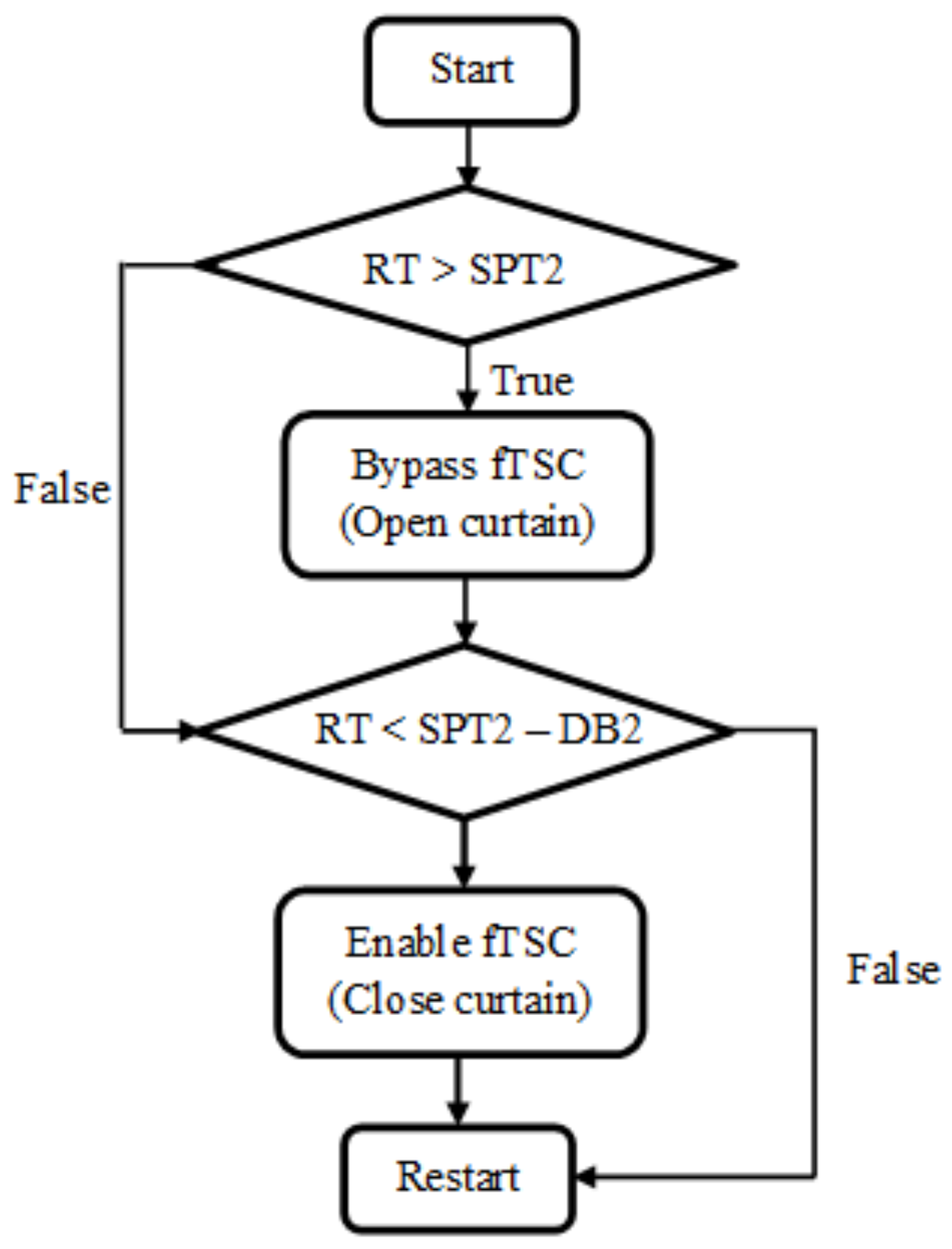
The fTSC was installed on the south-facing wall of the Test room (Figure 2). The system was designed as an enclosed plenum that covered the continuous inlet. Treated lumber was used for framing and support. Two layers of commercial dark grey, polypropylene landscape fabric (Dewitt, 12YR-450) with an area (Ac) of 12.7 m2 (11.3 m W × 1.2 m H) served as the solar collector. A clear, corrugated PVC sheet (0.66 m wide) and gutter were placed above the fTSC to prevent wetting of the fabric by rain. Dividing the airflow rate (Q) for the different variable-speed fan settings by Ac yield the vs. values (Table 1). The fabric had α of ~0.97 [10]. A layer of chicken mesh wire behind the fabric supported it while under suction. Pond liner and treated plywood were used to seal the bottom and the plenum sides, respectively; the pond liner had a sealable hole to drain any rainwater accumulating inside. The fabric transferred a portion of the absorbed solar heat to the fresh air passing through it due to suction created by the variable-speed fan. The heated air entered the room through the continuous baffle (inlet) (Figure 2). The system also recovered heat lost through the building envelope that accumulated in the fTSC plenum. A 0.4 m high bypass curtain above the fabric was lowered (Figure 2b) to prevent overheating. This curtain was controlled by an actuator coupled to a digital thermostat (Johnson Controls, Cork, Ireland, A 419). The flow-of-logic of the bypass curtain control is presented in Figure 3. To reduce propane use, the fTSC began operation before the heater was turned on and continued to operate after the heater turned off.
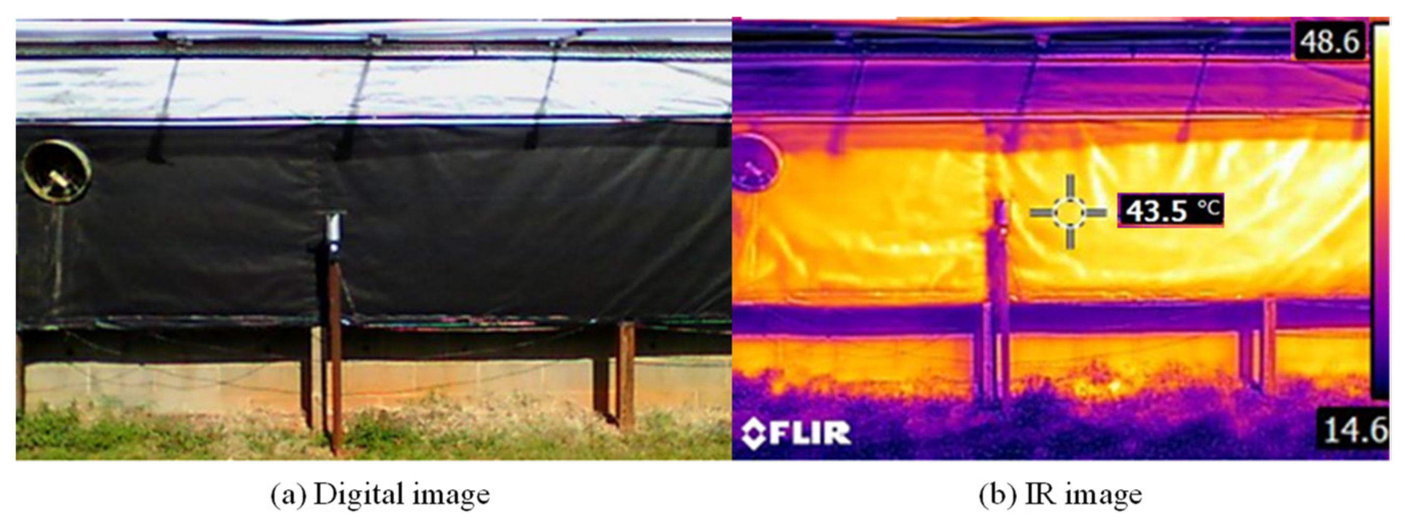
The much-higher porosity (β) of landscape fabric (vs. metal and PVC collectors) can cause preferential flow, leading to higher vs. closer to the inlet than farther away, or even flow-reversal [15]. While β of the landscape fabric was not calculated in this study, two layers of lighter landscape fabric had a β of 79% vs. β < 1.5% for the metal and PVC collectors [10]. Kutscher [15] reported that Δp ≥ 25 Pa prevented preferential flow in a metal TSC but a higher Δp threshold may be required for high-β collectors. Preferential flow was ruled out based on infrared images (Figure 4). No temperature difference was apparent between bottom and top of the fTSC (Figure 4); preferential flow would have been indicated by lower temperature closer to the top.
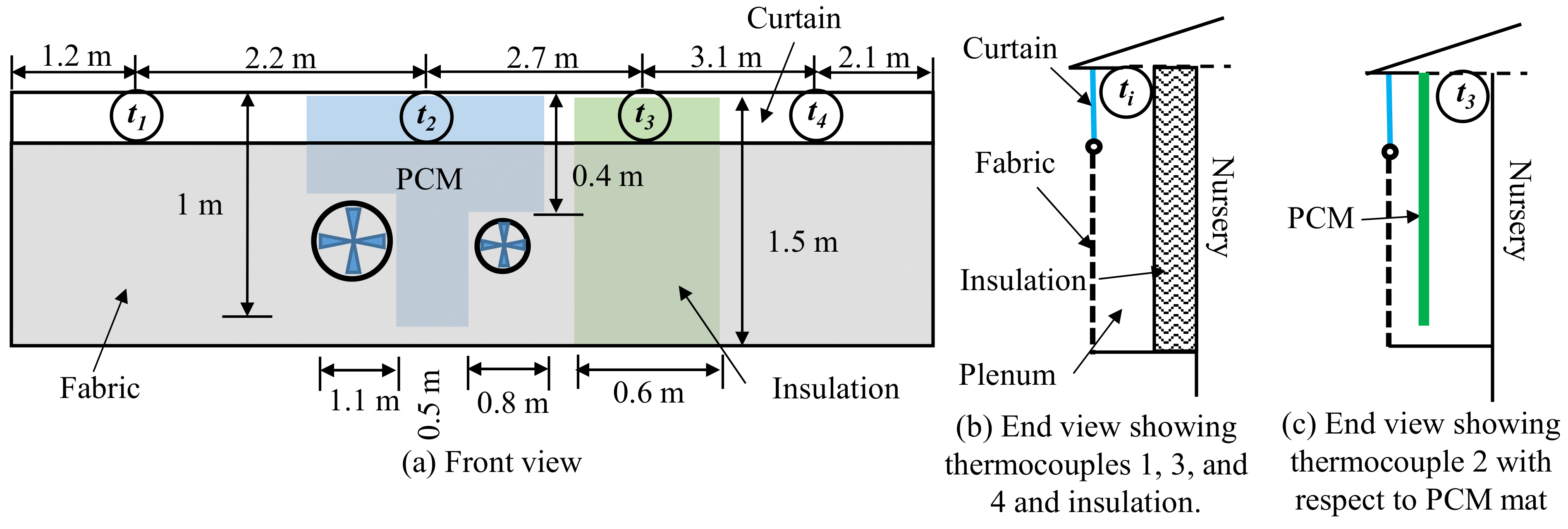
To isolate the effects of direct heating vs. indirect heating (recovery of heat lost through the building envelope), a 0.6 m × 1.5 m piece of insulation (51 mm thick polystyrene foam) (Figure 5) with a thermal resistance of 1.76 m2-C°/W was taped to the sidewall of the nursery. To evaluate the potential of heat storage for use after sundown, a 1.6 m2 piece of PCM mat (BioPCM Q25, total latent heat storage capacity of 60 kJ/m2, activated at 25 °C) manufactured by Phase Change Energy Solutions, was hung in the space between and above the two ventilation fans (Figure 5). Fresh air entering through the fTSC struck the PCM mat, traveled downward parallel to the mat, and then after passing through the 0.15 m gap between the PCM mat and bottom of the fTSC plenum, moved upward between the sidewall and PCM mat before entering the inlet. At plenum temperature ≥25 °C, the PCM would activate, absorbing latent heat, resulting in reduced temperature rise. When the plenum temperature decreased after sundown, the PCM would solidify, releasing heat for use in the barn. The instrumentation and methods used to separate the direct and indirect heating as well as the PCM heat storage effects are discussed in Section 2.3.

2.3. System Instrumentation and Analyses

All temperature measurements were made with type T thermocouples (accuracy: ±0.8 °C). Four thermocouples were installed at the inlets of the Test room in the plenum of the fTSC to measure tempered-air temperature (Figure 5). All the thermocouples were placed level with the inlets. The #1 and #4 thermocouples measured temperature rise both, due to direct and indirect heating (Figure 5). Thermocouple #2 was installed behind the PCM mat (Figure 5c). Thermocouple #3 installed in front of the polystyrene board (Figure 5b) only measured the Δt due to direct heating. Two thermocouples were installed at the air inlet of the Control room. Because fresh air entering the Control room was slightly warmer (due to the radiational heat gain from the metal roof) than ambient air, the average temperature of these thermocouples was considered to be the control temperature. All temperature measurements were taken every 5 s, and average values for every minute were recorded on a Campbell Scientific CR 1000 data logger.
Temperature rise caused by both direct and indirect heating was calculated as:
Δ t = t t t c
where tt and tc are the fTSC and Control temperatures, respectively. In Equation (1), tt is the average of temperatures measured by thermocouples #1, #3, and #4 and tc is the Control temperature. Including t3 (thermocouple #3 measurement) in calculating tt made Δt more representative though slightly conservative since t3 only measured the direct heating effect. Temperature change due to the PCM was calculated as:
Δ t p = t p t 1 , 4
where tp is the reading of thermocouple #2 and t1,4 is the average reading of thermocouples #1 and #4.
A solar irradiance sensor (Onset Computers, S-LIB-M003; accuracy: >±10 W/m2 or ±5%) installed at the geometric center of the landscape fabric monitored I received by the fTSC and the data recorded on a data logger (Onset Computers, Micro Station) every minute. Data from the data logger were downloaded using HOBOware (Onset Computers). Efficiency of the fTSC was calculated as:
η = Δ t c p m ˙ I α A c
where cp is specific heat of dry air at 25 °C (1005 J/kg-°C) and m ˙ is mass airflow rate (kg/s) through the fTSC (discussed below); the other terms were defined earlier. See Table 1 footnote for calculation. The numerator of Equation (3) yields the total power output (W) of the system. Efficiency was calculated only during 8 am to 5 pm when the curtain was closed, and I was >0.6 W/m2. A curtain status sensor monitored the status of the curtain every minute and this information was recorded on the CR 1000 data logger. An ultrasonic anemometer (R.M. Young Company, 85,000) installed 0.25 m in front of the fTSC (Figure 4) was used to monitor the effect of ambient wind on the fTSC performance since high ambient wind speeds increase convective heat losses particularly at low vs. values [15].
Two type T thermocouples were installed in each room to evaluate the effect of the fTSC on indoor temperatures. A carbon monoxide (CO) sensor and data logger (Lascar Electronics, EL-USB-CO300; range: 0–300 ppm; accuracy: ±5 ppm) and a carbon dioxide sensor (Vaisala, GMT22; range: 0–10,000 ppm; accuracy: ± (1.5% of range + 2% of reading)) were installed in each room to monitor indoor air quality only for Herd 1 (Section 2.4). A Hall-effect sensor was used to monitor rpm (Table 1) of the variable-speed fan and the signal was logged on the CR 1000 data logger. Two propane meters (EKM-PGM.75) were used to measure propane usage by the heaters in the Test and Control rooms.

2.4. Pig Placement and Management

This study was approved (protocol # 17-145-A) by the North Carolina State University Institutional Animal Care and Use Committee (IACUC). Two herds (batches) of piglets ~6.5 kg to 7 kg weaned at ~21 d were used in the study. For each herd, the Test and Control rooms had 120 piglets each. Herd 1 was placed on 6 December 2018 and removed on 30 January 2019 while Herd 2 was placed on 28 February and removed on 4 April 2019. The pigs were individually weighed initially and at the time of their removal. The ratio of average increase in mass of pig to the days yielded the average daily mass gain (ADMG) per treatment. Feed consumption ratio (FCR) for each treatment was calculated as the ratio of total mass of feed consumed to the total mass of live mass gained. Mortality was also tracked in both treatments for both herds.

3. Results and Discussion

3.1. Performance of fTSC

Performance of the fTSC as well as environmental and operating parameters for two representative periods are summarized in Table 2. Information in Table 2 is only for those days when the fTSC operated and the pigs required supplemental heating. Additional data and details are in Yu [11]. Fan speed was not monitored during Period 1 and the vs. (Table 2) was based on the 50% setting for the minimum ventilation fan (Table 1) based on pig age and season. In both periods, there were short-term increases in the speed of the minimum ventilation fan. While these transient values could not be accounted for in calculating the average vs. for Period 1 (part of Herd 1), during Period 2 (part of Herd 2), average vs. increased by much lower than 0.01 m/s.
Due to higher average I, Period 1 had higher average Δt and η (Table 2). Higher I in Period 1 was due to the lower solar elevation angle in late-December vs. March at the site latitude [16]. Shorter duration of fTSC operation in Period 2 may have also reduced performance (Δt and η). When the fTSC is bypassed, it cools down rapidly and requires more energy on resumption of operation to increase Δt and η. Shah et al. [4] also hypothesized that intermittent TSW operation in a pig nursery might have contributed to its reduced performance [4]. Convective heat loss increases with U, particularly when parallel to the collector [17], and it averaged 1.64 m/s at the site in Period 2 while it was not measured at the site in Period 1. However, wind-induced convective heat losses could be higher in low-β (usually, <1.5%) collectors than in the high-β (~80%) fTSC [10]. Due to higher Δt, the PCM absorbed more heat energy in Period 1, resulting in lower Δtp (Table 2). Heat release by the PCM after sundown is discussed below.
Based on measurements of thermocouple #3 vs. the average of measurements of thermocouples #1 and #4 (Figure 5), indirect heating (through heat recovery) by the fTSC accounted for 40% and 19%, respectively, of the Δt in Periods 1 and 2, respectively [11]. Greater indirect heating in Period 1 was due to longer fTSC operation (Table 2). As expected, the indirect heating component was typically higher early in the morning when I values were low [11]. Heat recovery by a TSC in a swine nursery was considerable [4]. Indirect heating due to recovery of building heat loss by a TSC, except standalone TSD (e.g., [5]), depends on inside temperature vs. ambient temperature, plenum temperature, and wall insulation, but because heat recovery is inherent in the operation of a TSC, it will not be further discussed.
A broiler house fTSC produced a maximum Δt of 20 °C with vs. values of 0.0079 m/s to 0.012 m/s; average Δt and η values were not reported. In the pig nursery, the TSW produced an average Δt of 7.6 °C (concomitant η not reported) with a vs. of 0.05 m/s [4]. The TSD used for heating Canadian broiler houses yielded average monthly Δt and η values in the ranges of 3.1 °C to 8.6 °C and 36% to 64%, respectively, with a vs. of 0.012 or 0.016 m/s [6]. The pTSC used for the turkey brooder room heating provided an average Δt of 8.1 °C (concomitant η not reported) at a vs. of 0.036 m/s [9]. Since the bench-scale fTSC had outperformed both TSC and pTSC [10], the fTSC performance (Table 2) was unexpectedly lower than the above studies. However, the performance of a collector depends on many different factors (e.g., tc, I, U, β, Vs) and their interactions. Hence, daily performance on days with different tc, I, and ON periods was analyzed in detail as shown below.
For 2 d (Trial 1) during Period 1 (Table 2), temperatures and I were analyzed (Figure 6 & Table 3); tc, tt, and tp are presented as moving averages (n = 15) to reduce short-term fluctuations due to measurement in moving air. To evaluate the impact of the PCM after sundown, Figure 6 includes data from 8 am to 8 pm. While data when the fTSC was bypassed was included in Figure 6, it was excluded in Table 3. Rapid increase in I at ~8:45 am on both days (Figure 6) was due to shading of the irradiance sensor by a shed ~9 m south of the fTSC earlier in the morning. The Test room had higher temperature than the Control room on both days; room temperatures are discussed in detail in Section 3.2.
As expected, tt varied with I on both days (Figure 6). Temperature rise was much lower on 29 December due to lower I (cloudy conditions) (Table 3). Higher average 10 m U (5.8 m/s vs. 4.5 m/s, 5 s sampling rate) on 29 December measured at the weather station <300 m to the south of the fTSC during 8 am to 5 pm might have reduced Δt by increasing convective heat losses vs. 26 December [17]. Since wind direction data was not collected at the site, its impact on fTSC performance could not be examined. Mean Δt on 26 December (Table 3) was comparable to mean daily Δt with a TSW [4] or weekly Δt with a TSD [9] despite lower I than the cited studies. The fTSC evaluated by Liang et al. [12] yielded a maximum Δt of ~20 °C though their vs. values were much lower than in this study and Δt increases as vs. decreases [17]. Performance of the fTSC on 26 December demonstrates its potential for effective air tempering.
On 26 December, tp increased until 2:30 pm but stayed below tt until ~4 pm (Figure 6) as the PCM melted and absorbed heat energy. While phase change occurs at constant temperature, gradual change in tp over time was likely due to the spatial variability in mat temperature even though the PCM activates at 25 °C (Figure 6). After 4 pm, tp was generally higher than both tt and tc (Figure 6) as the PCM began to solidify releasing heat even as both tt and tc decreased with I. On 26 and 29 December, between 4 pm and 9 pm, average tp values were higher than tc by 3.9 °C and 1.5 °C, respectively [11]; the smaller difference on 29 December was due to cloudy conditions. As expected, between 4 pm and 9 pm, the difference between tp and tt decreased over time [11] as the energy stored in the PCM was depleted. Hence, coupling the PCM with the fTSC could reduce overheating inside while increasing duration of air tempering compared to only the fTSC. Higher tempered air temperatures over a longer duration reported by Poole et al. [13] in a TSC-PCM system vs. this study could have been due to differences in energy storage capacity and design. Energy absorbed and released by the PCM was not calculated since airflow rate associated with the PCM could not be calculated.
Performance data of the fTSC for two days (Trial 2) with different environmental conditions and vs. values during Period 2 (Table 2) are presented in Figure 7 and the daily summaries are presented in Table 4. As in Trial 1, Figure 7 includes data for periods when the fTSC was bypassed (except Vs), while those data are excluded in Table 4. Temperatures in Figure 7 are presented as moving averages (n = 15). In Figure 7, U, Vs, and η values are only presented from 8 am to 5 pm, whereas to understand the impact of PCM the temperature data is presented from 8 am to 8 pm.
Shading due to trees led to rapid decrease in I around 4:30 pm on both days, resulting in sharp increases in η (Figure 7) which were due to a sharper reduction in the denominator vs. numerator of Equation (3). A sharp increase in η of due to a sharp decrease in I was also reported by others [4,6,9]. Wind direction was mostly parallel to the fTSC on both days (Figure 7). On 2 March, despite lower I, Δt was higher and therefore, η was much higher (Table 4). Higher Δt, despite lower I on 2 March vs. 6 March (Table 4), was unexpected since Δt increases with I [18]. In TSCs, Δt decreases as tc increases due to increased radiative heat loss [17], but in Trial 2 it was just the opposite (Table 4). On both days in Trial 2, since average U values were similar (Table 4) and wind directions were mostly parallel to the fTSC (Figure 7), reasons for higher Δt on 2 March vs. 6 March were unclear. Greater reduction in Δtp on 2 March vs. 6 March (Table 4) was likely due to higher Δt and tc which allowed PCM activation on 2 March but not on 6 March Activation of PCM on 2 March but not on 6 March is evident from the trends of tp, tt, and tc beginning around 5:30 pm (Figure 7). A PCM activating at lower temperature (e.g., 22 °C) could have increased heat storage.
Difference in performance of the fTSC between Period 1 (Figure 6, Table 2) vs. Period 2 (Figure 7, Table 3) was noteworthy and the reasons are partly unclear. With similar I and lower tc, Δt and η on 2 March 2019 (Period 2) should have been similar to or even higher (due to lower radiative heat loss) than Δt and η on 26 December 2018 (Period 1). The roles of U and wind direction could not be evaluated for Period 1 since those parameters were not measured at the site. However, intermittent operation coupled with lower tc on 6 March (Table 3) vs. 26 December (Table 2) might have contributed to reduced fTSC performance as has also been noted by others [4].
Increased convective and radiative heat losses due to low vs. (Table 2) vs. the design vs. (0.044 m/s) could have reduced the fTSC performance [15,17]. Excessive fTSC cycling due to oversized heater capacity (0.15 kW/pig) and high ventilation rate (Section 2.1) reduced operation time due to frequent failures of the curtain components, and increased propane use (Section 3.3). Cycling of the fTSC in commercial nurseries would be lower due to lower heater capacities (e.g., 0.09 kW/pig [4], 0.07 kW/pig [5]) and ventilation rates [14]. Finally, the fTSC would have been more effective in a house with air inlets on the sidewalls and the fans on the endwall (e.g., [5]), unlike this study where a portion of the tempered air pulled in through the fTSC was immediately short-circuited through the fan (Figure 2).

3.2. Environmental Conditions

Environmental conditions in the Test and Control rooms during the study are compared in Table 5. While the two rooms had the same average room temperature during most of Herd 1 (Table 5), during 22–31 December 2018, the Test room was ~1.5 °C warmer. For 19 h beginning 30 December 2018, the Test room was at 30.9 °C, ~4.9 °C higher (Figure 8) because its temperature sensor fell on the floor and the pigs began chewing on it. The resulting cooling of the sensor caused the heater to run longer resulting in a maximum temperature of 39.9 °C (Figure 8). This led to higher propane use (Section 3.3), CO2 concentration (1598 ppm vs. 1446 ppm in Control), and CO concentration (6.5 ppm vs. 1.5 ppm in Control) over that period. The Test room operated at higher temperatures in Herd 2 (Table 5, Figure 8). Sudden drop in the Control room temperature on 1 March for 7 h (Figure 8b) was because the larger ventilation fan was left on by mistake. For reference, temperature of the fresh air entering the Control room (tc) is also presented in Figure 8. It is clear from Figure 8, that diurnal tc spikes affected temperatures in both rooms more in Herd 1 than Herd 2.
Since the fTSC was an experimental system, for safety, a separate curtain controller was used. Due to difference in accuracies of the temperature sensors providing inputs to the curtain and environmental controllers, the fTSC did not work seamlessly with the heater and ventilation fans, leading to differences in temperatures between the Test and Control rooms and affecting propane use (Section 3.3).

3.3. Propane Use

Propane use in the two rooms are compared in Figure 9. Herd 1 was placed on 6 December 2018 but propane data for both rooms is from 12 December when the curtain controller was repaired. Averaged over both treatments, lower propane use in Herd 1 (Figure 9) despite colder conditions (average air temperature of 7.6 °C vs. 9.8 °C) and longer duration (49 d vs. 36 d) vs. Herd 2 was unexpected. The actual duration of Herd 1 was 55 d but propane use during the first 6 d was discarded because the fTSC had not become operational.
Daily propane use increased rapidly initially since the younger pigs needed more heating and plateaued at Day 24 in both herds [11]. In Herd 1, the Test room consumed 165% more propane despite the fTSC providing higher Δt and operating longer (or Period 1, Table 2) than Herd 2. For example, on 26 December 2018, between 8 am to 5 pm, the fTSC would have provided 150 MJ of solar heat, equal to 6.15 L of propane, calculated using the numerator of Equation (3), information in Table 1 and Table 3, and average energy value of propane (24.5 MJ/L) [19]. Greater propane use in the Test room could have been due to higher room temperatures at the start of monitoring and overheating during 30–31 December 2018 (Section 3.2), when the Test room consumed 15 L more propane than the Control room [11]. Since CO2 production increases with propane use, slightly lower CO2 concentrations in the Test room in Herd 1 (Table 5) indicated that its ventilation rate might have been higher, which also increased propane use.
In Herd 2, the Test room used 14% less propane than the Control room; the Test room might have saved more propane if the two rooms had been at the same temperature (Figure 8). Daily propane use in the Test and Control rooms were similar on 1 March when the Control room temperature declined for 7 h (Figure 8) due to accidental operation of the large ventilation fan. In a broiler house in Arkansas, the fTSC reduced natural gas usage by 7%, though only a fraction of the fresh air was pulled through the fTSC [12]. In two swine nurseries in North Carolina, propane uses were reduced by 8.5% by a TSW (also provided indirect heating) [4] and by 22.6% by a TSD (only direct heating) [5]. The fTSC was programmed to turn on before the heater came on and turn off after the heater had turned off but the oversized heater caused the curtain to open earlier, bypassing the fTSC and reducing propane savings.

3.4. Pig Performance

The pig performance parameters are presented in Table 6. There was no treatment effect on ADMG in Herd 1, but in Herd 2, it was significantly higher in the Control treatment (Table 6). Numerically, FCR was slightly lower (better) in the Test room in Herd 1 but substantially lower in the Control treatment in Herd 2 (Table 6). While mortality was numerically higher in the Test room in both herds, the opposite had been expected. Love et al. [5] hypothesized that superior pig and turkey performance in houses with TSD vs. control houses might have been due to improved air quality parameters that were not measured (e.g., CO). However, average CO was slightly higher in the Test room in Herd 1 in this study (Table 5). It is unclear if the slightly higher CO concentrations in the Test room early in the study [11], and particularly, the spike in CO concentration on 30 December 2018 (Section 3.2), led to higher mortality (Table 6). Compared with Herd 1, mortality in Herd 2 was much higher in the Test room (Table 6) but neither CO2 nor CO were monitored during this herd. A longer study with more herds might have allowed better evaluation of the impact of fTSC on pig performance. However, unlike [5], a TSW used in a pig nursery did not improve performance vs. control [4].

3.5. Scale-Up Considerations

Despite data loss due to frequent breakdown of the experimental system, the potential for using the fTSC for air heating in livestock barns and possibly in other applications was clearly demonstrated. The following scale-up considerations could make the system more cost-effective and robust for tempering air in livestock barns.
  • The fTSC must face preferably, south (or southwest or southeast) in the Northern hemisphere for greater I receipt during winter. Vertical deployment will allow greater I receipt in winter and reduce rainwater ingress than inclined deployment.
  • Since heat losses increase with decreasing Vs, operating the fTSC at a higher vs. (perhaps, >0.04 m/s) [10] could improve performance and reduce cost.
  • Controlling the fTSC with the barn environmental controller will allow the fans, heaters, and fTSC to work seamlessly. Since commercial houses have lower (and more appropriate) heater capacities [4,5] and ventilation rates [11], the integrated fTSC could work for longer durations, and provide more energy savings.
  • While heat recovery increases with PCM area, modeling could be used to determine its cost-effectiveness. Modeling could also include two PCMs with different activation temperatures (e.g., [13]) which might be beneficial also with older piglets that require less heating during daytime while still requiring air tempering after sundown.

4. Conclusions

An fTSC was evaluated in a swine nursery with two herds of piglets during December 2018–April 2019. The fTSC, made of two layers of dark grey commercial landscape fabric, had an area of 12.7 m2 and operated at average vs. of 0.027 m/s. In addition to fTSC performance, environmental conditions, propane use, and pig performance were compared between the fTSC-equipped Test room with an adjacent and identical Control room without the fTSC. The performance of a layer of PCM placed in the fTSC plenum was also evaluated. Key findings are:
  • During 9 h of operation on 26 December 2018, with a mean I of 592 W/m2 the fTSC increased air temperature by a mean of 11.6 °C (maximum of 19.8 °C) with a mean η of 89%. Lower performance on other days might have been due to sub-optimal operating (e.g., intermittent operation) and environmental (e.g., U) conditions.
  • For 5 h beginning 4 pm on 26 December 2018, the PCM increased mean air temperature by 3.9 °C, showing that it offered the potential to provide air tempering after sundown.
  • The Test and Control rooms had the same average air temperatures in Herd 1 but the Test room was slightly warmer in Herd 2. In Herd 1, CO2 concentration was slightly lower and CO concentration slightly higher in the Test room.
  • Despite substantial heating of the fresh air, the fTSC did not reduce propane use, probably due to its reduced operation (mainly, breakdowns) and because environmental and fTSC controllers did not work seamlessly.
  • Pig performance was unaffected by the treatment.
While the fTSC offered potential for cost-effective air tempering in livestock barns and other applications, it should be sized for higher vs. to improve performance and reduce cost. Controlling the fTSC with the house environmental controller could improve performance and reduce maintenance. Modeling the fTSC-PCM combination, including two PCMs with different activation temperatures could be more beneficial.

Author Contributions

Conceptualization: M.D.B. and S.B.S.; methodology: L.Y., S.B.S. and M.T.K.; formal analysis: L.Y., S.B.S., M.T.K. and L.F.S.; investigation: L.Y. and S.B.S.; resources: S.B.S. and M.T.K.; data curation: L.Y. and S.B.S.; writing—original draft preparation: L.Y.; writing—review and editing, S.B.S., L.Y. and L.F.S.; visualization: L.Y. and S.B.S.; supervision: S.B.S. and M.T.K.; project administration: S.B.S.; funding acquisition: S.B.S. and M.T.K. All authors have read and agreed to the published version of the manuscript.

Funding

L.Y. received financial support from the Biological and Agricultural Engineering Department, NC State University and College of Agriculture and Life Sciences’ Assistantship Assistance Program. Hog Slat constructed the fTSC frame at no cost and provided equipment at discounted prices. Phase Change Energy Solutions provided the PCM free-of-cost.

Data Availability Statement

Complete data generated during the study can be found at https://repository.lib.ncsu.edu/handle/1840.20/36824 (accessed on 23 October 2021).

Acknowledgments

The following people or units provided support during the project: E. Phil Harris, Jeff Wiegert, Jay Campbell, Justin Macialek, Clay Byrd, and other personnel and student workers at the Swine Education Unit.

Conflicts of Interest

The authors declare no conflict of interest. The funders had no role in the design of the study; in the collection, analyses, or interpretation of data; in the writing of the manuscript, or in the decision to publish the results.

Animal Care and Use

The pigs were cared for and used in this study per NCSU IACUC Protocol # 17-145-A.

References

  1. American Society of Heating, Refrigerating and Air-Conditioning Engineers (ASHRAE). Combustion and fuels. In ASHRAE Handbook–Fundamentals; ASHRAE: Atlanta, GA, USA, 2005; Chapter 18. [Google Scholar]
  2. Kalogirou, S. Solar thermal collectors and applications. Prog. Energy Combust. Sci. 2004, 30, 231–295. [Google Scholar] [CrossRef]
  3. Kutscher, C.F. Transpired solar collector systems: A major advance in solar heating. In Energy Business Technology Sourcebook, Proceedings of the 19th World Energy Engineering Congress, Atlanta, GA, USA, 6–8 November 1996; NREL Report (No. 24373); National Renewable Energy Laboratory: Golden, CO, USA, 1997; pp. 481–489. [Google Scholar]
  4. Shah, S.; Marshall, T.; Matthis, S. Transpired solar wall for tempering air in a swine nursery in a humid subtropical climate. Appl. Eng. Agric. 2016, 32, 115–123. [Google Scholar] [CrossRef]
  5. Love, C.D.; Shah, S.B.; Grimes, J.L.; Willits, D.W. Transpired solar collector duct for tempering air in North Carolina turkey brooder barn and swine nursery. Sol. Energy 2014, 102, 308–317. [Google Scholar] [CrossRef]
  6. Cordeau, S.; Barrington, S. Performance of unglazed solar ventilation air pre-heaters for broiler barns. Sol. Energy 2011, 85, 1418–1429. [Google Scholar] [CrossRef]
  7. Bansal, N.; Uhlemann, R. Development and testing of low cost solar energy collectors for heating air. Sol. Energy 1984, 33, 197–208. [Google Scholar] [CrossRef]
  8. Gawlik, K.M.; Kutscher, C.F. A Numerical and experimental investigation of low-conductivity unglazed, transpired solar air heaters. Sol. Energy 2002, 47–55. [Google Scholar] [CrossRef]
  9. Poole, M.R.; Shah, S.B.; Grimes, J.L.; Boyette, M.D.; Stikeleather, L.F. Evaluation of a novel, low-cost plastic solar air heater for turkey brooding. Energy Sustain. Dev. 2018, 45, 1–10. [Google Scholar] [CrossRef]
  10. Poole, M.R.; Shah, S.B.; Boyette, M.D.; Grimes, J.L.; Stikeleather, L.F. Evaluation of landscape fabric as a solar air heater. Renew. Energy 2018, 127, 998–1003. [Google Scholar] [CrossRef]
  11. Yu, L. Comprehensive Evaluation of a Landscape Fabric Based Transpired Solar Collector in a Pig Nursery. Master’s Thesis, NC State University, Raleigh, NC, USA, 2019. [Google Scholar]
  12. Liang, Y.; Janorschke, M.; Hayes, C.E. Low-Cost Solar Collectors to Pre-heat Ventilation Air in Broiler Buildings. In Proceedings of the 2021 ASABE Annual International Virtual Meeting, Virtual, 12–16 July 2021; American Society of Agricultural and Biological Engineers (ASABE): St. Joseph, MI, USA, 2021; p. 1. [Google Scholar]
  13. Poole, M.R.; Shah, S.B.; Boyette, M.D.; Stikeleather, L.F.; Cleveland, T. Performance of a coupled transpired solar collec-tor—phase change material-based thermal energy storage system. Energy Build. 2018, 161, 72–79. [Google Scholar] [CrossRef]
  14. MidWest Plan Service. MWPS-32 Mechanical Ventilating Systems for Livestock Housing, 1st ed.; Iowa State University: Ames, IA, USA, 1990. [Google Scholar]
  15. Kutscher, C.F. Heat Exchange Effectiveness and Pressure Drop for Air Flow Through Perforated Plates with and without Crosswind. J. Heat Transf. 1994, 116, 391–399. [Google Scholar] [CrossRef]
  16. Kaisen Online Calculator. Available online: https://keisan.casio.com/exec/system/1224682277 (accessed on 29 July 2021).
  17. Kutscher, C.F.; Christensen, C.B.; Barker, G.M. Unglazed Transpired Solar Collectors: Heat Loss Theory. J. Sol. Energy Eng. 1993, 115, 182–188. [Google Scholar] [CrossRef]
  18. Leon, M.A.; Kumar, S. Mathematical modeling and thermal performance analysis of unglazed transpired solar collectors. Sol. Energy 2007, 81, 62–75. [Google Scholar] [CrossRef]
  19. Alternative Fuels Data Center (AFDC). Fuel Properties Comparison. Available online: http://www.afdc.energy.gov/fuels/fuel_comparison_chart.pdf (accessed on 29 July 2021).
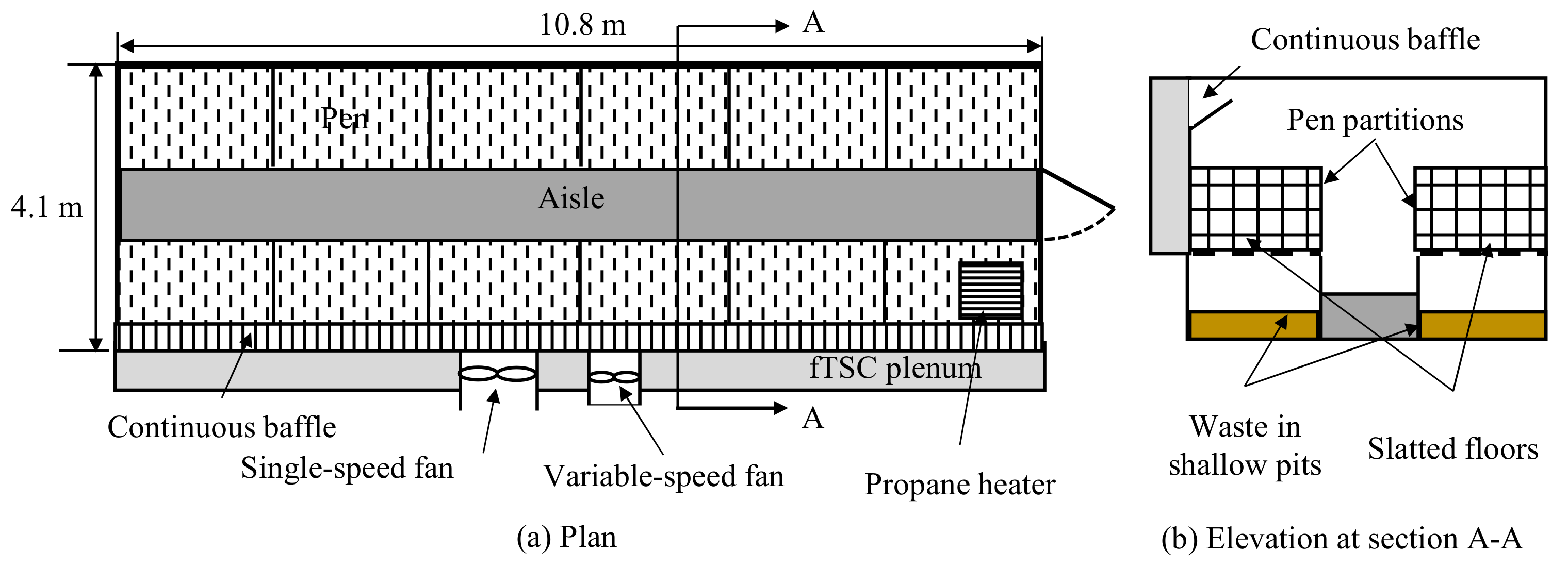
Figure 1. Layout of the Test room where (a) shows the plan and (b) shows the elevation. The Control room was across the hallway from the Test room and identical to the Test room but without the fTSC plenum. Not to scale.
Energies 14 07258 g001
Figure 2. The pig nursery fTSC system where (a) shows the digital image and (b) shows schematic.
Energies 14 07258 g002
Figure 3. Curtain controller flow-of-logic. Measured room temperature, digital thermostat set-point temperature, and dead-band are denoted by RT, SPT2, and DB2 (1.7 °C), respectively.
Energies 14 07258 g003
Figure 4. Concomitant digital and infrared (IR) images of the fTSC taken on 13 February 2019 at 12:19 pm. vs. was 0.027 m/s. In the figure, (a) shows the digital image and (b) shows the infrared image. Note the ultrasonic anemometer mounted on the metal post and the temperature scale on the right of Figure 4b.
Energies 14 07258 g004
Figure 5. Locations of the thermocouples (t1,…, t4) in the fTSC plenum. In the figure, (a) shows the front view, (b) shows the end view sectioned at the insulation but showing the locations of thermcouples 1, 3, or 4 (as indicated by ti) in the plenum, and (c) the end view sectioned at thermocouple 2 to show its location with respect to the PCM in the plenum. Not to scale.
Energies 14 07258 g005
Figure 6. Temperatures (moving averages) and irradiance (I) on (a) 26 December and (b) 29 December 2018 in Trial 1. Legend in Figure 6a indicates plenum temperature as tt; PCM temperature as tp; control temperature as tc; Test room temperature as tTR; and Control room temperature as tCR. Measurements were made every minute. On 29 December data were lost for ~30 min from 12:39 pm.
Energies 14 07258 g006
Figure 7. Environmental and operating conditions and fTSC performance on (a) 2 March and (b) 6 March 2019 in Trial 2. Figure 7(a1,b1) present temperature and irradiance (I) data; Figure 7(a2,b2) present wind speed (U) and efficiency (η); Figure 7(a3,b3) present suction velocity (Vs); and Figure 7(a4,b4) present wind roses for the 2 d. Legend in Figure 7(a1) indicates plenum temperature as tt; PCM temperature as tp; control temperature as tc; Test room temperature as tTR; and Control room temperature as tCR. Only temperatures are presented as moving averages. Wind speed data in Figure 7(a4,b4) are in m/s. Measurements and calculations were made every minute. Data for U, η, and, vs. are only presented from 8 am to 5 pm whereas temperature data are from 8 am to 8 pm.
Energies 14 07258 g007
Figure 8. Average hourly Test room (tTR) and Control room (tCR), and Control (tc) temperatures for Herds (a) 1 and (b) 2. Data presented are shorter than the actual durations (Herd 1: 6 December 2018–30 January 2019; Herd 2: 28 February–4 April 2019) due to loss of data.
Energies 14 07258 g008
Figure 9. Comparison of propane use in the Test and Control rooms in Herd 1 (12 December 2018–30 January 2019) and Herd 2 (28 February–4 April 2019). Herd 1 propane use does not include the first 6 d.
Energies 14 07258 g009
Table 1. Correlation among the variable-speed fan’s setting, speed, and mass airflow rate.
ParametersFan Setting
50%60%70%80%90%100%
Fan speed (rpm) 190710461300137614551626
Vol. airflow rate (Q, m3/s) 20.3370.3630.4340.4720.5290.566
Suction velocity (Vs, m/s) 30.0270.0290.0340.0370.0420.045
Mass airflow rate (kg/s) 40.3990.4300.5140.5590.6260.670
1 Measured with Hall-effect sensor (Section 2.3). 2 Measured with the balometer. 3 Section 2.3. 4 Q times air density of 1.1839 kg/m3 (25 °C, dry air).
Table 2. Average control temperature (tc), incident solar irradiance (I), suction velocity (Vs), fTSC temperature rise (Δt, Equation (1)), temperature change due to PCM (Δtp, Equation (2)), and fTSC efficiency (η, Equation (3)). Only data collected during 8 am to 5 pm when the fTSC was operating were used. All measured and calculated averages are based on 1 min measurements.
PeriodPig Age & Datestc
(°C)
I
(W/m2)
Vs
(m/s)
Δt (°C)Δtp
(°C)
η
(%)
fTSC Operation (%)
1Day 17–24 1
22–29 December 2018
15.54310.0275.5−4.68998
2Day 3–16
2–15 March 2019
14.12580.0272.6−1.04551
1 Herd age in the nursery.
Table 3. Mean and maximum control temperature (tc), incident solar irradiance (I), fTSC temperature rise (Δt Equation (1)), temperature change due to PCM (Δtp, Equation (2)), and fTSC efficiency (η, Equation (3)) on 2 days in Trial 1, 2018. Data is for 8 am to 5 pm and only when the fTSC operated.
Date & TimeDuration of fTSC Operation (h) tc
(°C)
I
(W/m2)
Δt
(°C)
Δtp
(°C)
η
(%)
26 December9.0Mean13.459211.6−6.989
Max. 119.386419.80.9
29 December8.5Mean21.24553.1−3.720
Max. 126.28228.22.3
1 Maximum values are for duration, not coincident maximum associated with Vs.
Table 4. Mean and maximum control temperatures (tc), wind speed (U), solar irradiance (I), suction velocity (Vs), fTSC temperature rise (Δt), temperature change due to PCM (Δtp), and fTSC efficiency (η) on 2 days in Trial 2, 2019. Data is for 8 am to 5 pm and only when the fTSC operated. All parameters are based on 1 min measurements.
Date & TIMEDuration of fTSC Operation (h) tc
(°C)
U
(m/s)
I
(W/m2)
Vs
(m/s)
Δt
(°C)
Δtp
(°C)
η
(%)
2 March5.8Mean15.11.14500.0275.6−2.152
Max. 122.99.99070.04012.52.0
6 March5.1Mean8.01.25960.0273.9−1.525
Max. 112.38.27880.0329.91.7
1 Maximum values are for the duration, not coincident maximum associated with Vs.
Table 5. Average hourly room temperatures, CO2 concentrations, and CO concentrations in the Test and Control rooms in Herds 1 and 2.
Herd (Dates)Temperature (°C) 1CO2 (ppm) 2CO (ppm) 3
TestControlTestControlTestControl
1 (6 December 2018–30 January 2019)23.4 423.4 41371 51441 51.71.2
2 (28 February–4 April 2019)26.8 625.9 6Not measured
1 Average of two thermocouple readings per room measured every minute. 2 One sensor per room measuring every minute. 3 One sensor per room measuring every 15 min. 4 22 December 2018 to 30 January 2019. 5 Data from 18 December 11:15 am to 19 December 6:30 pm were lost. 6 28 February to 26 March 2019.
Table 6. Pig performance in the Test and Control rooms in Herds 1 and 2.
TreatmentADMG 1 (kg/d)FCR 2 (kg-Feed/kg-Live Mass)Mortality (%)
Herd 1Herd 2Herd 1Herd 2Herd 1Herd 2
Test0.54 ± 0.080.36 ± 0.081.361.490.84.2
Control0.55 ± 0.090.39 ± 0.081.391.4100
p-value 30.330.04Not analyzed due to lack of replicates
1 Average daily mass gain. 2 Feed conversion ratio. 3 Treatments compared using analysis of variance at α = 0.05 with mortalities excluded.
Publisher’s Note: MDPI stays neutral with regard to jurisdictional claims in published maps and institutional affiliations.