Abstract
Warm plasma techniques are considered a promising method of tar removal in biomass-derived syngas. The fate of another problematic syngas impurity—hydrogen sulfide—is studied in this work. It is revealed that processing simulated syngas with a microwave plasma results in hydrogen sulfide conversion. For different gas flow rates (20–40 NLPM) and hydrogen sulfide concentrations ranging from 250 ppm to 750 ppm, the conversion rate varies from ca. 26% to 45%. The main sulfur-containing products are carbon disulfide (ca. 30% of total sulfur) and carbonyl sulfide (ca. 8% of total sulfur). Besides them, significantly smaller quantities of sulfates and benzothiophene are also detected. The main components of syngas have a tremendous impact on the fate of hydrogen sulfide. While the presence of carbon monoxide, methane, carbon dioxide, and tar surrogate (toluene) leads to the formation of carbonyl sulfide, carbon disulfide, sulfur dioxide, and benzothiophene, respectively, the abundance of hydrogen results in the recreation of hydrogen sulfide. Consequently, the presence of hydrogen in the simulated syngas is the main factor that determines the low conversion rate of hydrogen sulfide. Conversion of hydrogen sulfide into various sulfur compounds might be problematic in the context of syngas purification and the application of the right technique for sulfur removal.
1. Introduction
With the consequent and accelerating departure from fossil fuels, biomass gasification might be considered a promising alternative [1]. This is not only due to biomass neutrality in carbon dioxide emissions, but also due to gasification flexibility. Producer gas—the product of gasification—may be used in energy and heat production as well as to obtain syngas or hydrogen [1]. However, in practice, the utility of the process gas can be strongly limited by its quality, because many impurities, such as ash, hydrogen sulfide, ammonia, and tar, are generated during the gasification of biomass [2].
Tar is considered to be a major problem of biomass gasification. It is a complex mixture, mainly composed of heavy aromatic compounds, that can be defined and classified into many categories [3]. The common feature of these compounds is their ease of condensation at low temperatures. Consequently, they create a hazard of technical problems, e.g., malfunction of machines used for energy production and the fouling of pipelines as well as filters [1,4]. Therefore, a firm, proven, and effective technique of reducing the tar content in the process gas is essential for the wide commercialization of biomass gasification.
To overcome this obstacle, many methods have been investigated, i.e., primary, mechanical, thermal, catalytic, and plasma methods [3]. Recently, the latter have been gaining increasing attention because they allow tar to be converted into valuable products, usually with a high conversion rate. Moreover, in contrast to other methods, which require exploitation materials such as catalysts, liquid absorbents, or solid adsorbents, plasma methods require only electricity. This can be provided by renewable energy sources, such as wind or solar energy. Being electricity-sourced devices, plasma setups allow for a quick ON and OFF procedure and flexible control of the process parameters. The most common plasma techniques investigated for tar conversion are: corona discharge [5,6], dielectric barrier [7,8,9], arc plasma [10], gliding arc plasma [11,12,13,14,15], and microwave (MW) plasma [16,17]. Among them, gliding arc plasma and microwave plasma have been subjected to quite intensive investigation in recent years. Both of them can be classified as warm plasma, meaning that despite their nonthermal character, their gas temperature can reach a few thousand K [11]. Although both technologies have their pros and cons, MW plasma has the advantage of being based on proven and mature technology, as the magnetrons used in microwave plasma generation have been successfully used on an industrial scale for heating [18]. Moreover, these elements are produced by many companies, making them easily accessible and relatively cheap [18,19]. Additionally, with their power ranging from a few to hundreds of kW, this technology seems to have a high potential for scaling up.
Despite these advantages of warm plasma, there is an infinitesimal amount of research on its application in syngas treatment. Although there are many studies dedicated to tar removal, there are barely a few works considering the influence of the main syngas components (i.e., carbon dioxide, methane, carbon monoxide, and hydrogen) on this process. Moreover, to the best of the authors’ knowledge, there is no research dedicated to understanding the behavior of one of the main syngas impurities, i.e., hydrogen sulfide. The presence and fate of this compound can be crucial in the context of the final application of syngas. Since plasma techniques can be considered quite expensive and technically advanced, it seems only logical that they should be applied in technology that is also advanced and most profitable. Therefore, one of the solutions is to match plasma techniques with hydrogen or clean syngas production, which can be used in the chemical synthesis of many valuable products [2]. In fact, this is still the most common and profitable application of coal gasification [20]. On the other hand, applying plasma in biomass-derived syngas cleaning is not fully justified in the context of electricity and heat production due to their relatively low price. Moreover, the impurity limits for internal combustion engines (ICE), considering syngas, are significantly higher than in the case of fuel cells or chemical synthesis purposes. For example, tar concentration limits can be achieved solely by using state-of-the-art downdraft gasifiers [21]. This specific contradistinction of a “low-requirement” downstream application of syngas (e.g., ICE) and “high-requirement” applications (e.g., hydrogen/syngas production) is crucial not only in the context of the final product price and tar concentration requirements but also in the context of H2S content. In the case of an IC engine, the presence and nature of S compounds is of secondary importance, since most of the compounds will be transformed into sulfur oxides and further removed with the use of well-known and established cleaning technologies widely used in the combustion field. On the other hand, high-requirement applications require the use of catalysts, as in the case of the water–gas shift reaction (Fe or Cu catalyst), ammonia synthesis (Fe catalyst), methanol synthesis (Cu or Zn catalyst), and Fischer–Tropsch synthesis (Fe or Co catalyst). It is well known that metallic catalysts can be easily deactivated by all sulfur compounds (e.g., sulfur dioxide, hydrogen sulfide, carbonyl sulfide, and carbon disulfide) [22]. However, different sulfur compounds are removed with different efficiency and may require different removal methods [23,24,25,26]. Additionally, catalyst poisoning may progress differently depending on the sulfur compound [27].
In the work of Materazzi et al. [26] it was shown that organic sulfur compounds tend to transform into more stable hydrogen sulfide and carbonyl sulfide during arc plasma treatment of the producer gas obtained from waste gasification. Furthermore, in the work of Mousavi et al. [28], gliding arc steam reforming of simulated biogas led to H2S decomposition and oxidation to sulfate. Although these pieces of research clearly show that sulfur compounds can be affected by a high plasma temperature, they involved different plasma sources and conditions that were significantly different from those in the present work. Therefore, the purpose of the present work is to investigate the fate of hydrogen sulfide (as the main S source in syngas [29]) during MW plasma valorization of simulated biomass-derived syngas. To fulfill this goal, a series of experiments with different gas compositions, based on real biomass-derived syngas and with the addition of hydrogen sulfide, is conducted. Qualitative and quantitative analyses of the sulfur compounds present in the process gas are performed to determine the fate of hydrogen sulfide. The obtained results, showing how the main syngas compounds affect hydrogen sulfide in a warm plasma environment, should provide valuable information for any possible warm plasma installation with the purpose of syngas treatment and purification.
2. Materials and Methods
2.1. The Experimental Setup
Figure 1 presents a scheme of the experimental setup. Its heart is a microwave plasma reactor with a 600 mm quartz tube and a fixed microwave power of c.a. 1800 W (with the socket power of the MW source being 3000 W). The reactor is described with more detail in previous works [30,31]. The volumetric gas flow rate was set to 20, 30, or 40 normal liters per minute (NLPM), depending on the experiment. These values were chosen based on previous research to provide a stable work of the plasma reactor. The simulated biomass-derived syngas was composed of cylinder gases. The gases included nitrogen, hydrogen, carbon monoxide, carbon dioxide, methane, and a 10% mixture of hydrogen sulfide in nitrogen. Their flow rate was controlled with mass flow controllers (MFCs) (Aalborg XFM47 for nitrogen and β-ERG 1000 for hydrogen sulfide) or rotameters (for carbon monoxide, carbon dioxide, methane, and hydrogen). The concentration of the main components was set up at ca.: 21% of H2, 4% of CH4, 21% of CO, and 20% of CO2. The concentration of hydrogen sulfide was ca. 250 ppm, 500 ppm, or 750 ppm, depending on the experiment. The remaining gas was nitrogen. To measure the concentration of carbon monoxide, carbon dioxide, and hydrogen, a gas analyzer (GAS 3000, GEIT, Bunsbeek, Belgium) was connected to the outlet of the reactor. For methane and sulfur compound (sulfur dioxide, hydrogen sulfide, carbonyl sulfide, and carbon disulfide) determination, the gaseous samples were collected into Tedlar bags and analyzed using gas chromatography (GC). Since the volumetric flow of the gas changed as the gas was processed, argon was added as an internal standard to determine these changes. These tests were done separately with the use of GC and an argon volumetric concentration of 2%. For the test with a tar surrogate, a syringe pump (NE-300, New Era Pump Systems, Farmingdale, NY, USA) was used to provide toluene in the gaseous mixture, which was introduced into the plasma reactor via a heated hose (120 °C). The initial concentration of toluene was set to 10.0 ± 0.5 g/Nm3. The unprocessed toluene and the products of its conversion were collected in three impinger bottles filled with 20 mL of isopropanol. This was achieved by passing the process gas (10 L) through the set of impinger bottles. The obtained solution was analyzed with the use of GC techniques. A similar approach was applied for the detection of sulfate ions—the gas (10 L) was passed through two impinger bottles filled with 20 mL of deionized water, with the water samples being analyzed with the use of a Dionex ICS-1100 Ion Chromatography (IC) System (Thermo Fisher, Waltham, MA, USA).
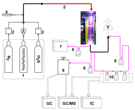
Figure 1.
Experimental setup: 1—gas cylinders; 2—mass flow controller; 3—rotameter; 4—syringe pump; 5—heated hose; 6—microwave plasma reactor; 7—gas analyzer; 8—peristaltic pump; 9—Tedlar bag; 10—impinger bottles; V—vent; GC—gas chromatograph; MS—mass spectrometer; and IC—ion chromatograph.
Three types of GC sets with different detectors were used to analyze the collected samples: mass spectrometry (GC/MS) (7820 with MSD 5977, Agilent, Santa Clara, CA, USA), a flame-ionized detector (GC-FID) (6890, Hewlett-Packard, Palo Alto, CA, USA), or a thermal conductivity detector (TCD) (7820, Agilent, Santa Clara, CA, USA). The purpose of the analysis, the applied columns, and the temperature programs are set out in Table 1. The GC/MS identification of compounds was initially performed with the use of Agilent MassHunter software (based on the NIST-14 MS library), and all the quantified compounds were confirmed by the use of chemical standards. The ion chromatography system, which was used in the measurements, consisted of a Dionex IonPacAS22 (2 × 250 mm; Thermo Fisher, Waltham, MA, USA) analytical column, a Dionex IonPacAG22 (2 × 50 mm; Thermo Fisher, Waltham, MA, USA) guard column, and a Dionex Anion MicroMembrane Suppressor Dionex AERS 500 4 mm (Thermo Fisher, Waltham, MA, USA). The capillary guard and capillary column were heated to a 30 °C temperature. The measurement system was an isocratic delivery system (the eluent composition and concentration remain constant throughout the run) which used an eluent with a composition of 4.5 mm of sodium carbonate and 1.4 mm of sodium bicarbonate. The eluent flow rate was 0.3 mL/min.

Table 1.
GC methods applied in the experiments.
As the temperature and pressure in the laboratory were 19.5 ± 1.0 °C and 102.0 ± 2.5 kPa, respectively, it was assumed that all the tests were done in NTP conditions (according to NIST).
2.2. Assessment Methods
The conversion efficiency of toluene (XC7H8) was calculated as follows:
where C0—initial concentration of toluene (g/Nm3), C—final concentration of toluene (g/Nm3), Vin—volumetric gas flow rate at the inlet of the plasma reactor (Nm3/h), and Vout—volumetric gas flow rate at the outlet of the plasma reactor (Nm3/h).
The energy efficiency (ηe) was calculated as follows:
where SEI (specific energy input) was:
where P—microwave plasma generator power supply (3 kW).
Sulfur compound distribution among the products was defined as follows:
where x refers to the sulfur compounds at the outlet of the reactor, i.e., not converted hydrogen sulfide, carbon disulfide, carbonyl sulfide, and benzothiophene; —mass flow rate of sulfur (g/min); and H2SIN—inlet hydrogen sulfide.
Hydrogen sulfide conversion was determined as below:
2.3. Uncertainty of Measurement
The GC quantitative analyses involved at least three tests for each sample. The results represent an average value. The uncertainty analysis involved standard deviation, residual standard deviation, and equipment uncertainty.
3. Results and Discussion
3.1. MW Plasma Impact on Syngas Composition
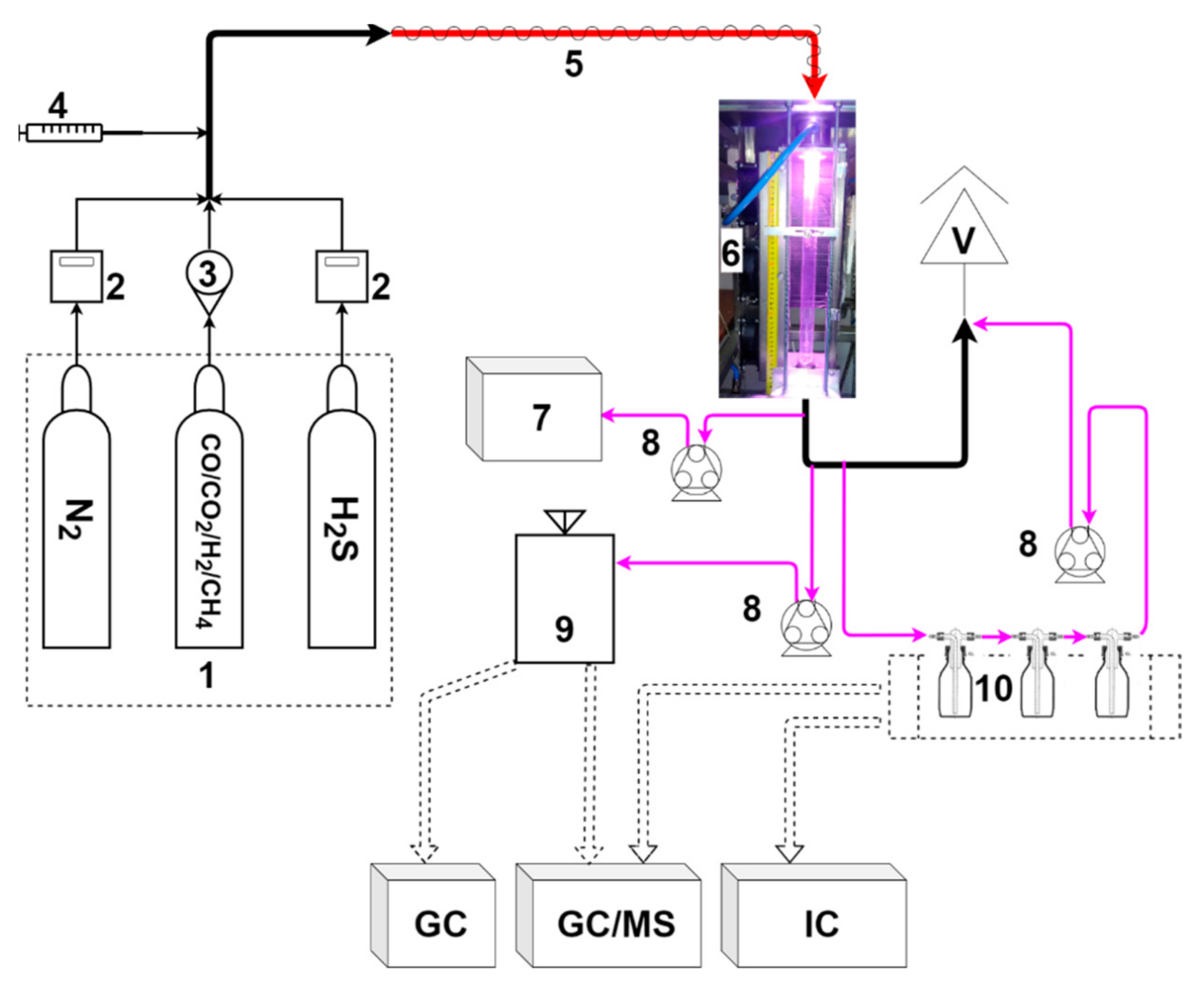
MW plasma is a high-temperature medium. For the reactor used in this work and similar conditions, the temperature in the core of the plasma was determined to be ca. 5000 K [16,31]. Along the reactor’s quartz tube the temperature drops from ca. 1900 K to 1000 K [16]. In such conditions, the main syngas components, i.e., nitrogen, carbon dioxide, methane, and hydrogen, can be easily dissociated [30,31]. However, the final composition of syngas is mostly affected by the presence of carbon dioxide and its interaction with methane and hydrogen, as presented in reactions (6) and (7):
Consequently, as presented in Figure 2, the share of carbon monoxide is significantly increased at the cost of carbon dioxide and methane, while the concentration of hydrogen is rather stable. Within the investigated range, the gas composition is only slightly affected by the gas flow rate.
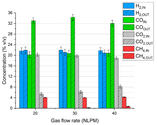
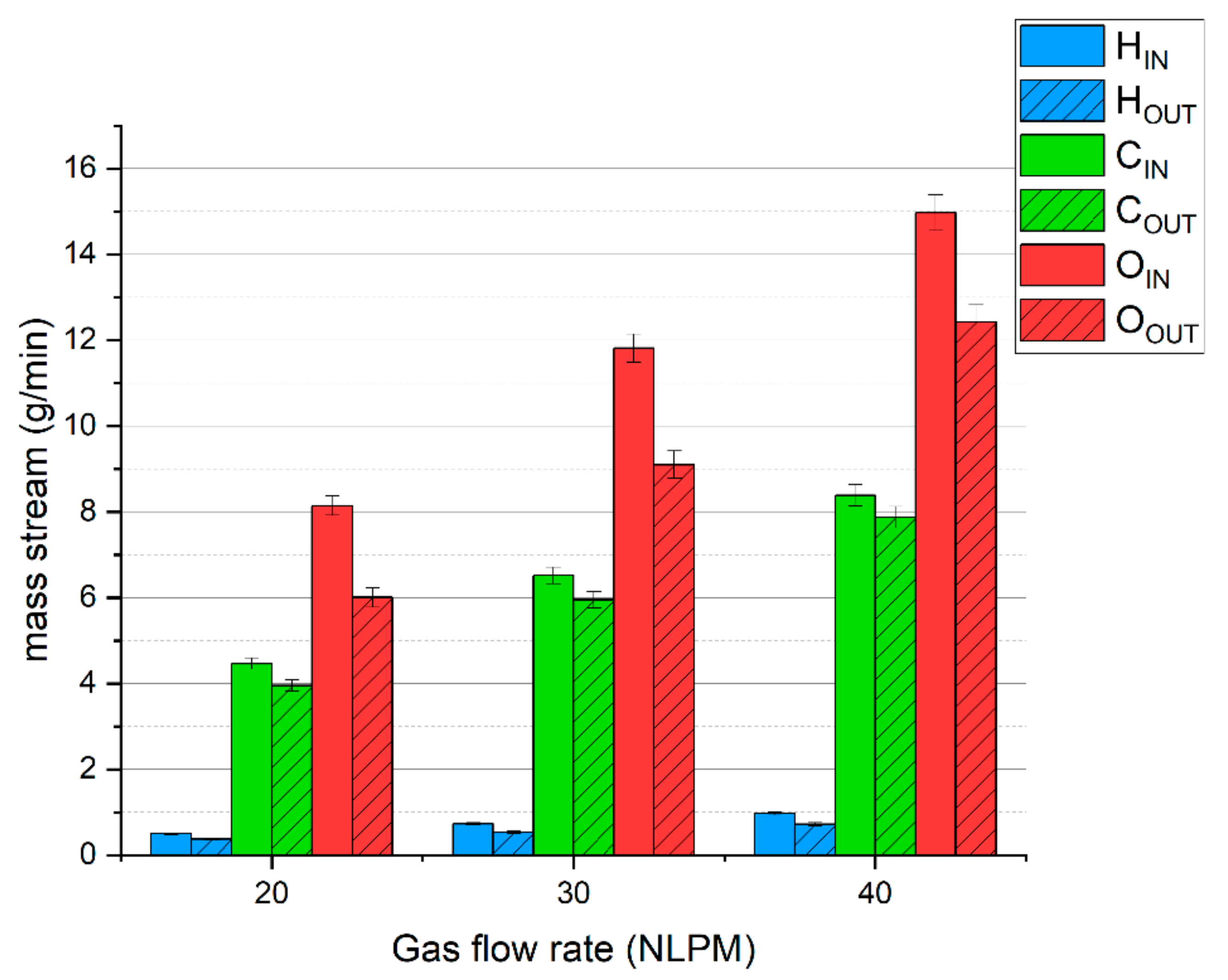
Figure 2.
Microwave plasma impact on syngas composition depending on the gas flow rate.
To complement these results, Figure 3 presents the balance of hydrogen, carbon, and oxygen. The average deficiencies of these elements are ca. 26%, 9%, and 22%, respectively. A high lack of hydrogen and oxygen is caused by the presence of steam, which was not analyzed, but was produced according to reaction (7). The lack of carbon is due to the presence of olefins (mostly acetylene) and hydrogen cyanide. The presence of these compounds was confirmed in our previous research [31].
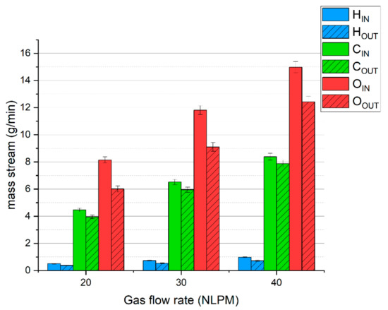
Figure 3.
The balance of basic elements of the simulated syngas during MW plasma treatment.
The high temperature of the plasma and the presence of syngas components also affect the tar compounds [31]. Toluene was chosen as a tar surrogate as it is one of the main components of biomass-derived tar that is often chosen to substitute real tar in laboratory experiments [4]. The test was conducted with a gas flow rate of 30 NLPM. Table 2 presents the results of toluene conversion in MW plasma.
Table 2.
Parameters of toluene conversion in MW plasma.
The energy efficiency and conversion rate fit within a wide range of parameters that were achieved for different plasma methods. For instance, for the gliding arc plasma reactor, the conversion rate usually exceeds 90%, yet the energy efficiency can vary from 0.12 to 796 g/kWh [11]. However, it should be noted that the reported experiments of tar conversion are rarely conducted in similar conditions. Very often there is a difference in tar surrogate nature, its concentration, gas flow rate, and gas composition. Moreover, it should be noted that this work was not focused on process optimization. It can be assumed that most of the fixed 3 kW inlet energy is lost through heat loss in the magnetron (the laboratory 2.45 GHz magnetrons have an efficiency of 60%) and reactor (as it was not insulated). Adjusting the microwave power, implementing 915 MHz magnetrons (with an efficiency of ca. 85%), and the limitation of heat loss or its recovery should improve the energy efficiency.
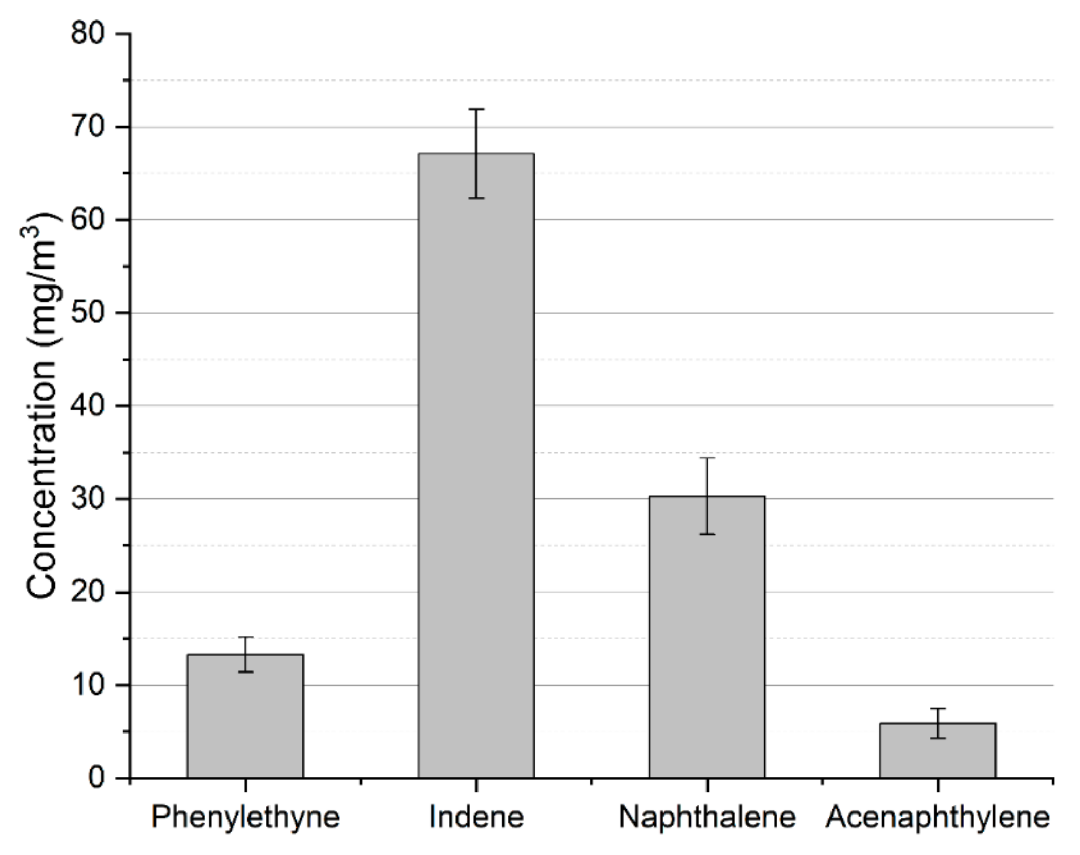
While most of the toluene is converted into valuable carbon monoxide and hydrogen due to interaction with carbon dioxide and steam (produced via reaction (7)) [16,31], part of it is converted into other aromatic compounds. The concentration of these compounds in the process gas is presented in Figure 4. Besides these heavier compounds, the other aromatic byproduct is benzene. Its concentration was determined to be 1.65 ± 0.22 g/Nm3. The presence of these products might be problematic. In the case of heavier aromatic hydrocarbons, the problem is connected to the tar dew point—the temperature at which the tar starts to condense. In opposition to toluene, which condenses at a rather low temperature, heavier aromatics, e.g., indene, naphthalene, and acenaphthylene, increase the tar dew point. Benzene, on the other hand, while not problematic in the context of tar condensation, is rather unwanted in the case of fuel cells or synthesis processes as it may create a carbon deposit on anodes and catalysts [32,33].
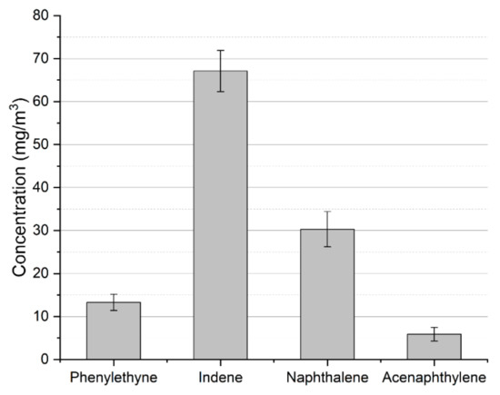
Figure 4.
Heavier aromatic byproducts of toluene conversion in MW plasma.
It should be noted that a more detailed description of MW plasma, its impact on syngas components, and the interaction between them are the subjects of previous works [16,30,31,34]. The results presented in this section are included due to the fact that a different gas composition was applied and a different tar surrogate was chosen when compared to previous works. Most importantly, they provide a background to discuss the fate of hydrogen sulfide during MW plasma syngas valorization.
3.2. Hydrogen Sulfide Conversion
For analyzing the fate of sulfur in the MW plasma syngas valorization process the sulfur-containing compounds were reduced to only one—hydrogen sulfide—as its concentration is usually a few times higher than that of other S compounds [26,29]. The initial concentration of hydrogen sulfide was set to 250 ppm, 500 ppm, or 750 ppm. While typically the concentration of hydrogen sulfide in real biomass-derived syngas is on a level below 200 ppm [35], some types of biomass show a higher concentration, e.g., 600 ppm [36]. Moreover, higher concentrations provided higher sensitivity and reliable measurements.
The initial step of the experiment involved the processing of hydrogen sulfide with pure nitrogen plasma and with the addition of one of the main syngas components, i.e., carbon monoxide, hydrogen, methane, and carbon dioxide, with their concentration kept as mentioned in Section 2.1. These tests were done with a gas flow rate of 30 NLPM and a H2S concentration of ca. 600–700 ppm. The goal was to identify the possible sulfur products with the outcome presented in Table 3. Additionally, the table includes the concentrations and conversion rates of hydrogen sulfide.
Table 3.
H2S conversion in nitrogen and two-component plasma.
Results from the table indicate that the addition of carbon dioxide and carbon monoxide increases hydrogen sulfide conversion when compared to pure nitrogen plasma. On the contrary, the presence of methane and hydrogen results in a higher concentration of hydrogen sulfide at the outlet of the reactor. In general, it can be assumed that within a high plasma temperature hydrogen sulfide is almost completely decomposed into hydrogen and diatomic gaseous sulfur, according to reaction (8):
This reaction is reversible and endothermic [28]. Consequently, in the lower part of the reactor, where the temperature is lower, and with an abundance of hydrogen (whether from hydrogen addition or methane decomposition), hydrogen sulfide can be recreated. With the addition of carbon monoxide and carbon dioxide, hydrogen sulfide can be transformed into carbonyl sulfide and sulfur dioxide, as presented in the simplified, exemplary reactions (9)–(11) [28,37], thus limiting the outlet concentration of hydrogen sulfide.
With the addition of methane, the GC/MS analysis revealed the presence of carbon disulfide, which can be produced according to reactions (12) and (13) [38]:
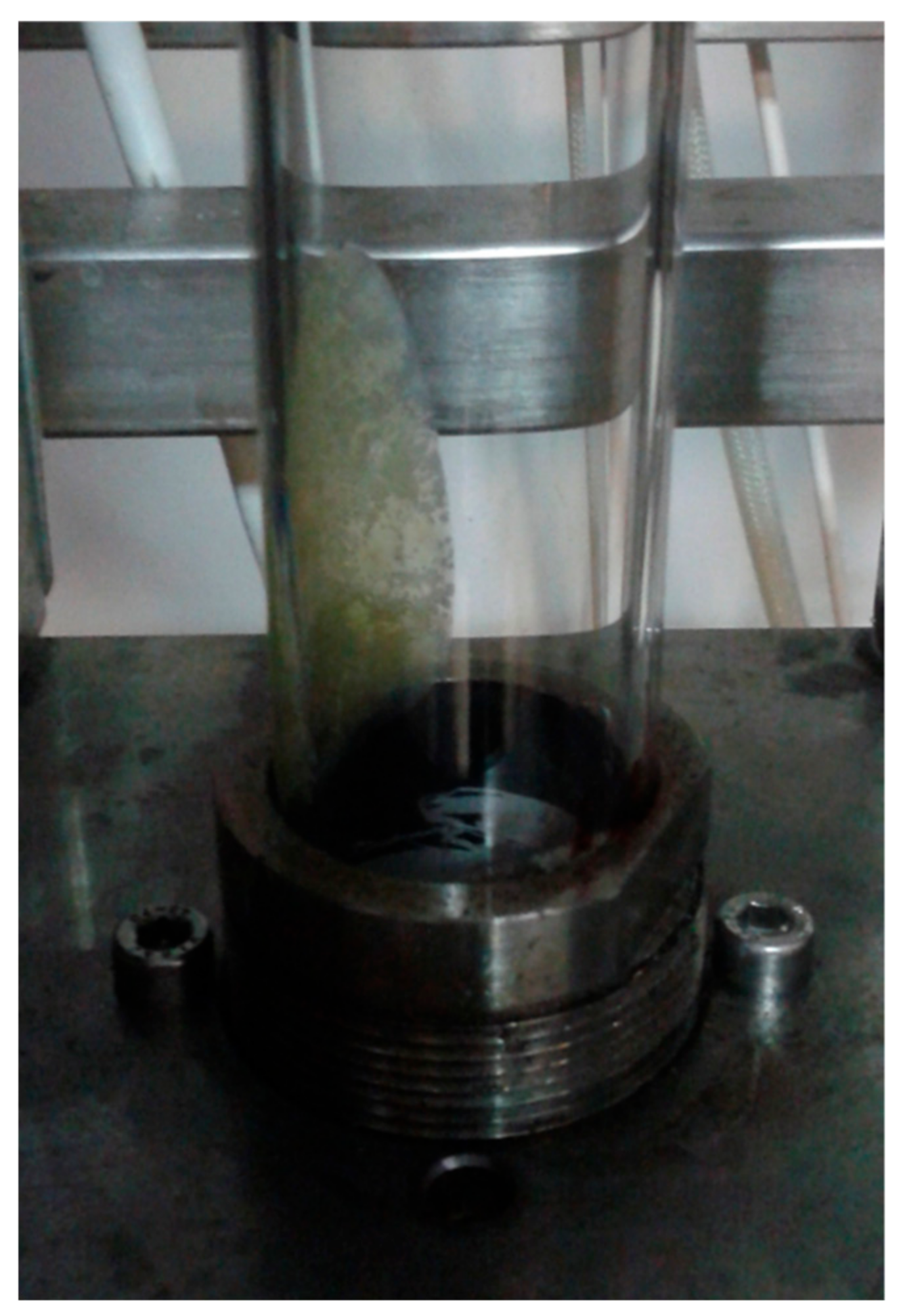
It is worth mentioning that reaction (12) might be another factor responsible for the drop in hydrogen sulfide conversion when methane was added. Besides these three gaseous products, i.e., carbonyl sulfide, sulfur dioxide, and carbon disulfide, the conversion of hydrogen sulfide also leads to the production of elementary sulfur deposits (Figure 5). These deposits, being S2 condensed on the reactor’s walls, were observed in the tests with pure nitrogen and with the addition of hydrogen and carbon monoxide. They were not observed in the case with carbon dioxide. With methane addition, the carbon deposits did not allow the condensed sulfur to be observed.
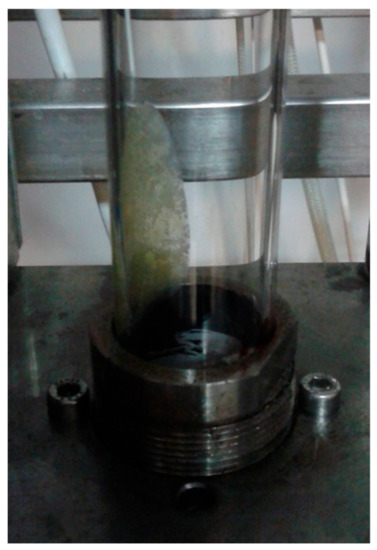
Figure 5.
Sulfur deposit on the reactor’s wall.
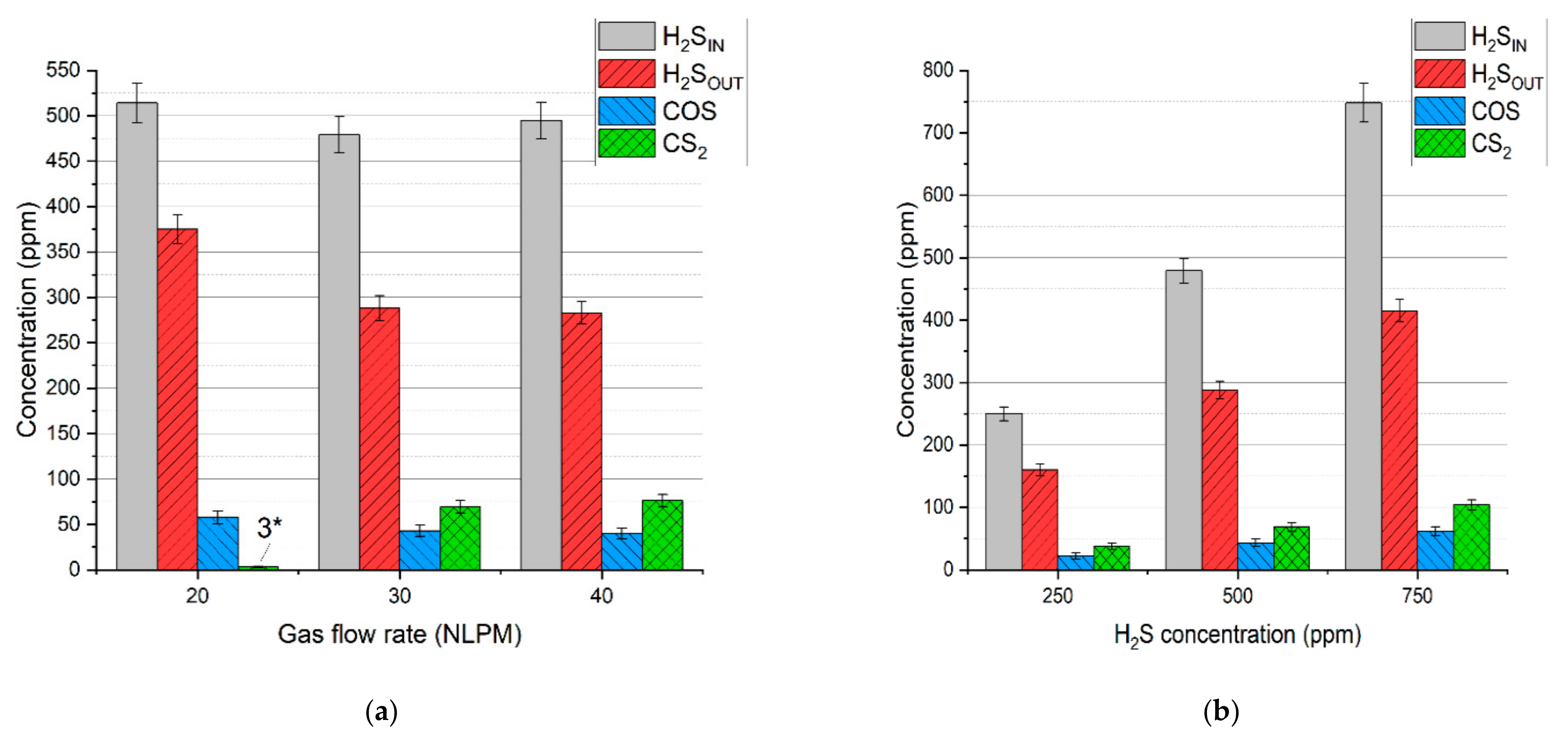
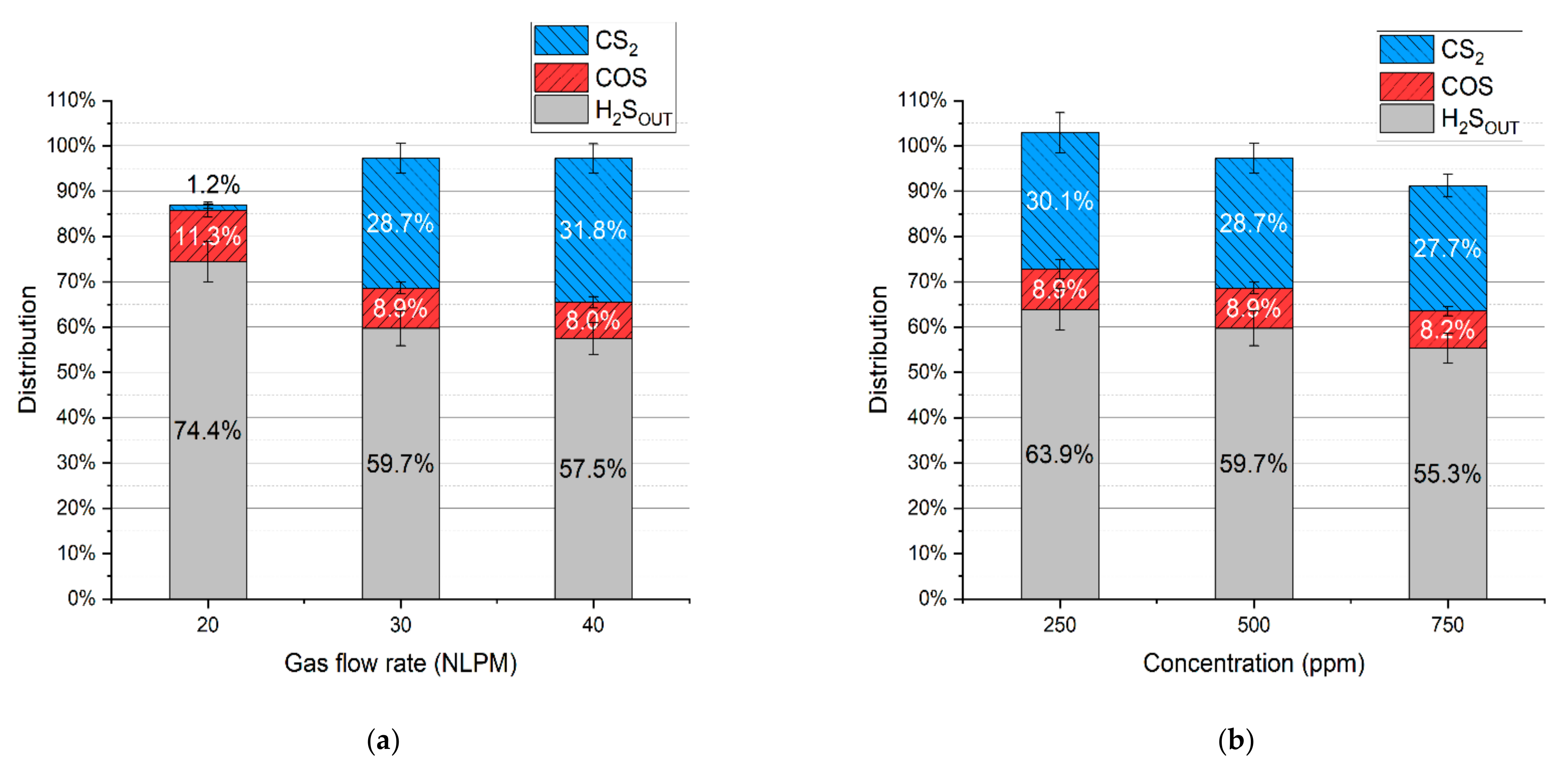
In the case of the test with simulated syngas containing all the permanent gases, i.e., carbon dioxide, carbon monoxide, hydrogen, methane, and nitrogen, the main dominating sulfur products were hydrogen sulfide, carbon disulfide, and carbonyl sulfide, with no sulfur deposits. Concentrations of these products are presented in Figure 6a,b. Based on these results and the gas flow rates, the distribution of hydrogen sulfide, carbonyl sulfide, and carbon disulfide was calculated (according to Equation (4)) and presented in Figure 7a,b.
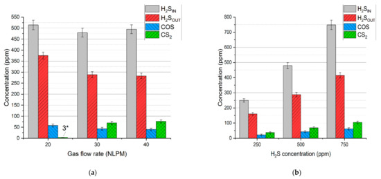
Figure 6.
Concentration of the gaseous sulfur compounds depending on: (a) gas flow rate and (b) initial hydrogen sulfide concentration. *—concentration below the calibration range.
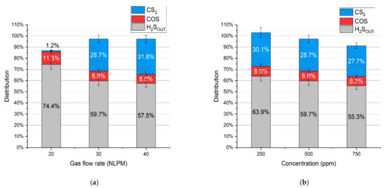
Figure 7.
Distribution of sulfur in the products depending on: (a) gas flow rate and (b) initial hydrogen sulfide concentration.
It should be noted that the distribution of sulfur in hydrogen sulfide indicates its conversion rate. Taking that into account, the conversion rate of hydrogen sulfide for the test with a gas flow rate of 20 NLPM, 30 NLPM, and 40 NLPM is 25.6% ± 4.0%, 40.3% ± 3.5%, and 42.5% ± 3.2%, respectively. In the case of the test with the hydrogen sulfide concentration set to 250 ppm, 500 ppm, and 750 ppm, the conversion rate is 36.1 ± 4.8%, 40.3% ± 3.5%, and 44.7% ± 2.8%, respectively. As can be seen, the increase in the gas flow rate and hydrogen sulfide inlet concentration results in a higher conversion rate (within the tested range). When compared to the results with pure nitrogen and two-component mixtures (Table 3), it seems that these conversion rates are closer to the tests with hydrogen and methane addition despite the presence of carbon oxides. Moreover, no sulfur dioxide was detected in the process gas. These phenomena can be possibly explained by the interaction between sulfur-containing compounds and the main syngas components. An example of this interaction might be reactions (14)–(16), which can be responsible for the recreation of H2S [39,40,41]:
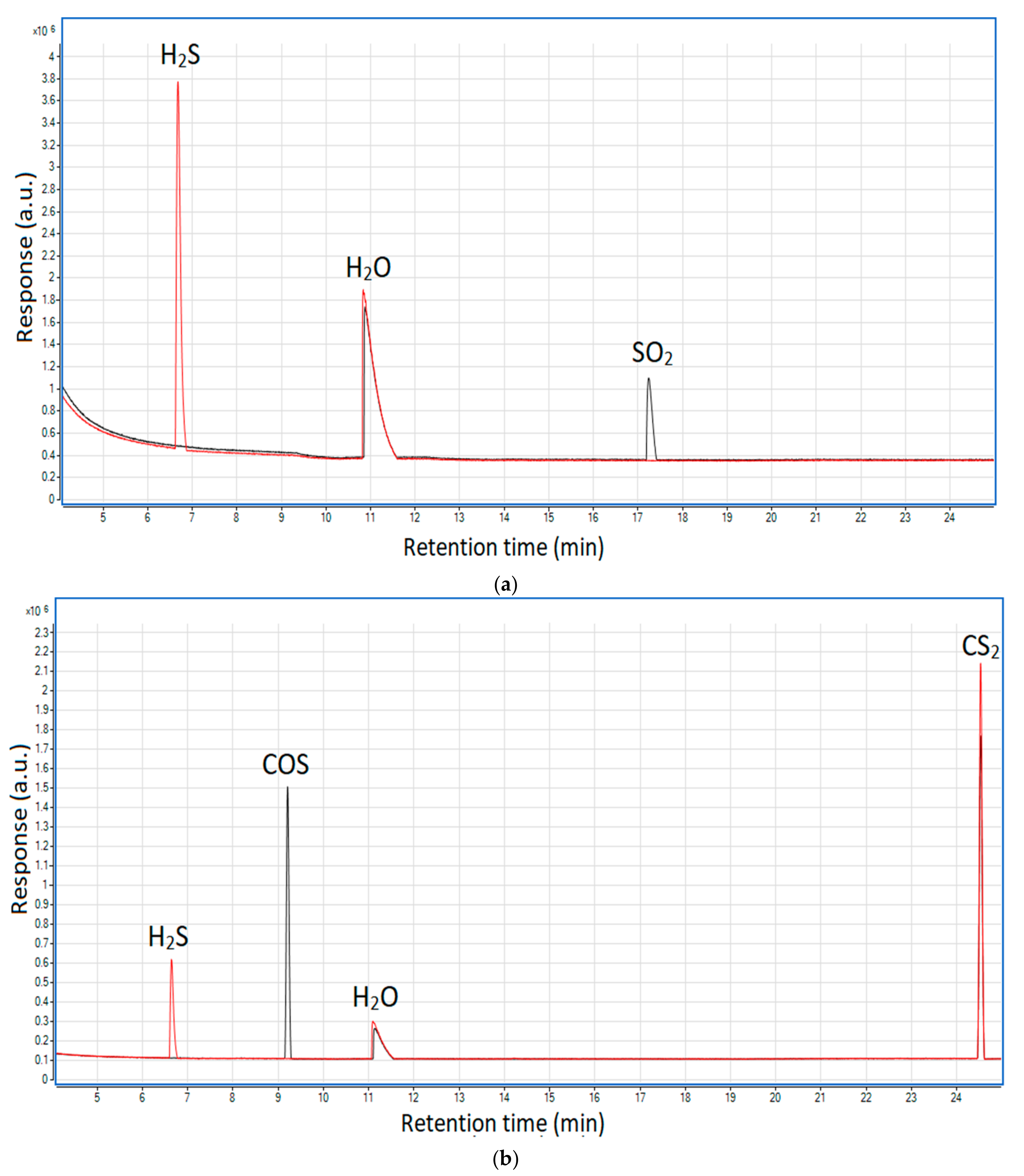
To validate the occurrence of these reactions in the MW plasma reactor, additional qualitative tests were done. They included two gaseous mixtures composed of nitrogen and hydrogen (21% v/v) along with sulfur dioxide (ca. 2000 ppm) or carbonyl sulfide and carbon disulfide (ca. 400 ppm each). The GC/MS results of these tests are presented in Figure 8a,b.
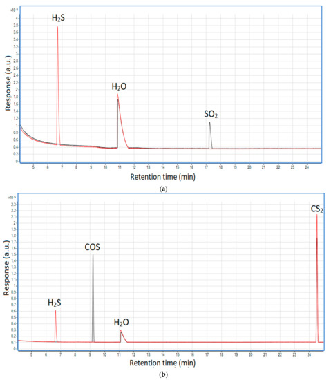
Figure 8.
Chromatograms showing the influence of hydrogen on hydrogen sulfide formation: (a) from sulfur dioxide and (b) from carbonyl sulfide and carbon disulfide. Black line—before the plasma reactor; red line—after the plasma reactor.
As shown, at the outlet of the reactor neither sulfur dioxide nor carbonyl sulfide was present; instead, hydrogen sulfide appeared—this proves that the presence of hydrogen may lead to the recreation of the latter from the former two. In the case of carbon disulfide, its concentration is very similar in both cases—before and after the plasma. This suggests that reaction (16) is thermodynamically unfavorable in the plasma conditions, which is consistent with the simulated syngas tests (Figure 7) that show the highest distribution of carbon disulfide among the sulfur products (excluding hydrogen sulfide).
Another reason for no sulfur dioxide in the outlet gas might be the insufficiency of oxygen. In the case of the run with the N2+CO2 mixture, hydrogen sulfide could be easily converted into sulfur dioxide due to the excess of oxygen from carbon dioxide dissociation. In the tests with simulated syngas oxygen was also consumed in reactions with methane and hydrogen, thus potentially limiting the formation of sulfur dioxide. Furthermore, the consumption of methane could have inhibited the formation of carbon disulfide (as in reaction (13)). This assumption might be reflected in the results—with an increase in gas flow rate, the conversion of methane decreases (Figure 2), and so the distribution of carbon disulfide increases. This is most evident in the case of 20 NLPM. With the lowest gas flow rate, the reaction time was enough to practically completely convert methane (Figure 2). Consequently, the concentration of carbon disulfide is also close to zero (Figure 6a).
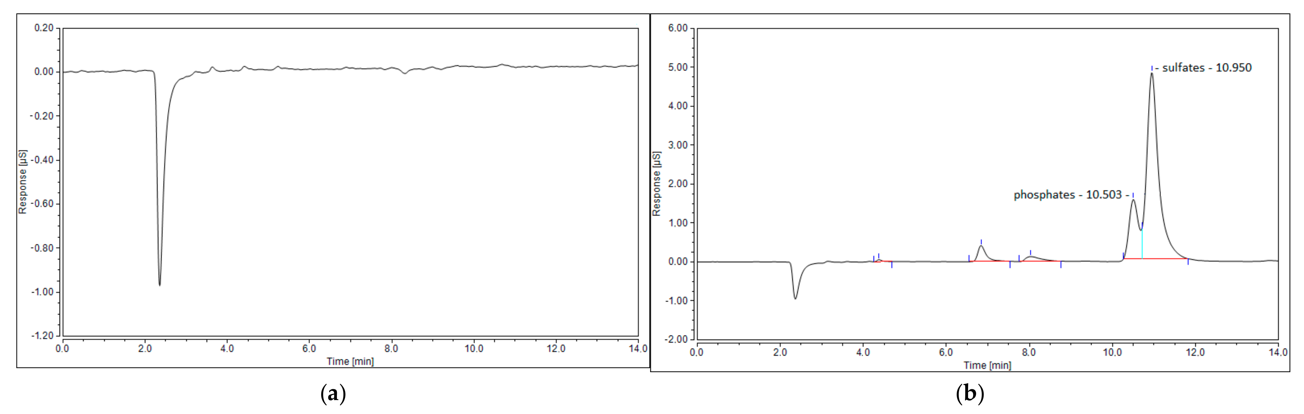
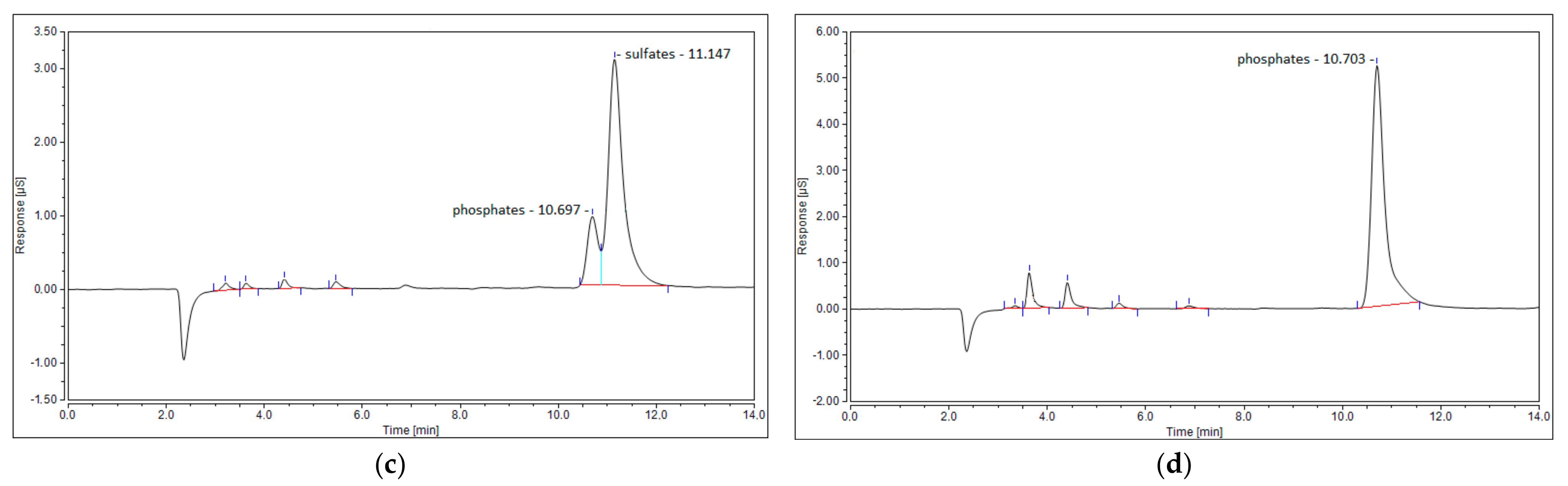
The last possible reason for no sulfur dioxide detection could be its reaction with steam, created via reaction (7), and the formation of sulfuric acid. This phenomenon was observed in the work of S.M. Ali Mousavi et al. [28]. To verify this phenomenon, ion chromatography tests were conducted for four samples: the blank test with pure ionized water, the sample obtained for the test with the N2+CO2+H2S mixture, and the samples obtained from the test with simulated syngas (20 NLPM and 30 NLPM). As shown, the peak obtained for the test with simulated syngas and 20 NLPM (Figure 9c) is similar in shape to the peak obtained for the test with the N2+CO2+H2S mixture (Figure 9b). There was no possibility to specify or quantify these ions, but the results clearly suggest that the outlet gas stream contains sulfates. On the other hand, the case with simulated syngas and 30 NLPM lacks a clear sulfates’ peak (Figure 9d), although it is possible that it could be overlapped by the previous one that was assigned to phosphates. This difference between the tests with 20 NLPM and 30 NLPM is somehow consistent with the distribution of sulfur products. In the case of 20 NLPM, there is a significantly higher lack of S compared to the case of 30 NLPM. This is indicated by the sum of the distribution of sulfur products, which is ca. 87% for the former one and ca. 97% for the latter (Figure 7). It is possible that the remaining sulfur is contained in sulfates. Nevertheless, in the cases other than 20 NLPM, these sulfur lacks are reasonably within the error bars, and it might be assumed that the sulfate concentration is rather negligible and that majority of the sulfur is contained within hydrogen sulfide, carbon disulfide, and carbonyl sulfide.
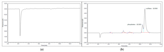
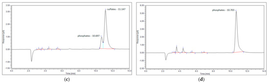
Figure 9.
Ion chromatogram of four samples: (a) blank sample; (b) N2+CO2+H2S mixture; (c) simulated syngas—20 NLPM; and (d) simulated syngas—30 NLPM.
Besides the already discussed sulfur compounds, the other possible ones are organic. However, none of the volatile organic sulfur compounds were detected in the gaseous samples. This seems natural, as the high plasma temperature is not favorable for the synthesis of these compounds and would rather lead to their prompt decomposition [26]. One exception might be aromatic sulfur compounds, e.g., thiophene or benzothiophene. They might be formed directly from sulfur sources and unsaturated hydrocarbons which are present in the process gas. Moreover, they show rather high thermal stability [26]. Therefore, a test to detect heavier organic sulfur compounds in the outlet stream was conducted. This test involved simulated syngas with a gas flow rate of 30 NLPM, a H2S concentration of 500 ppm, and the addition of toluene (10 g/Nm3). This was done by passing the process gas through impinger bottles filled with isopropanol. The GC/MS analysis revealed only the presence of benzothiophene. However, its concentration was as low as 19 mg/Nm3, which corresponds to an S distribution of 0.73%. Additionally, a test without toluene was conducted but no benzothiophene was detected. This was done since the presence of methane in the gaseous mixture leads to the formation of unsaturated hydrocarbons [31] which could potentially be involved in the formation of benzothiophene. Consequently, this shows that benzothiophene is generated directly from the tar surrogate or its derived aromatic byproducts.
Summarizing, the presented results prove that applying warm plasma to syngas valorization results in the transformation of hydrogen sulfide into various sulfur compounds. This creates a potential problem, as these compounds should be removed if syngas application involves catalytic processes. With a differential mixture of sulfur compounds, the purification process would probably be much more complicated and demanding. For instance, syngas application in synthesis processes usually involves hydrogen sulfide removal on zinc oxide adsorbents. In the case of carbonyl sulfide, this approach is rather inefficient [42]. In general, the simplest ways of hydrogen sulfide removal involving absorption/adsorption techniques, such as scrubbers, active charcoal, or molecular sieves, are not that effective in the removal of carbonyl sulfide and carbon disulfide [43]. Moreover, the presence of heavier hydrocarbons, e.g., benzene that was produced in toluene conversion, may lead to accelerated saturation of absorbents/adsorbents as the heavy organic compounds can be easily separated along with sulfur compounds [43,44]. One of the solutions might be hydrodesulfurization (HDS), which would transform carbonyl sulfide, carbon disulfide, and sulfur dioxide back into hydrogen sulfide with the use of hydrogen and CoMo or NiMo catalysts [41]. This would create the possibility to apply typical hydrogen sulfide removal methods, yet they still would be somehow limited by the presence of heavier hydrocarbons. In addition, it should be noted that benzothiophene, which was produced in the syngas valorization process, is one of the compounds that is highly resistant to the HDS process [45]. All these aspects show that the warm plasma valorization of syngas may complicate the process of sulfur removal, and that this issue should be treated with care when considering warm plasma application in tar conversion.
4. Conclusions
The transformation of hydrogen sulfide during microwave plasma treatment of simulated syngas is evaluated in this work. The conversion rate of hydrogen sulfide ranges between 26% and 45% depending on the gas flow rate and the initial concentration of hydrogen sulfide. The fate of hydrogen sulfide is strongly impacted by the presence of the main syngas components, with the main conclusions as follows:
- The presence of carbon monoxide, carbon dioxide, methane, and toluene in syngas leads to the formation of carbonyl sulfide, sulfur dioxide, carbon disulfide, and benzothiophene, respectively.
- The abundance of hydrogen in syngas leads to the recreation of hydrogen sulfide at the cost of carbonyl sulfide and sulfur dioxide.
- Consequently, the conversion rate of hydrogen sulfide in syngas is rather low. The main sulfur compound in the outlet stream of the processed gas is hydrogen sulfide. The share of the rest of sulfur products can be presented followingly: CS2 > COS >> sulfates, and benzothiophene.
In the context of applying warm plasma to syngas valorization, the transformation of hydrogen sulfide into various sulfur compounds might be problematic. The processed syngas would presumably require more complex sulfur removal techniques than in the case of hydrogen sulfide being the only sulfur contaminant. It should be noted that hydrogen sulfide removal prior to plasma treatment is rather out of scope, as it would require gas cooling, which would lead to tar condensation and heat loss. Therefore, a universal purification technique should be implemented at the outlet of the plasma reactor to remove the sulfur compounds. Investigation of these techniques should be the goal of future work.
Author Contributions
Conceptualization, M.W.; methodology, M.W. and W.M.; validation, M.W. and W.M.; formal analysis, M.W.; investigation, M.W. and W.M.; resources, M.W.; data curation, M.W. and W.M.; writing—original draft preparation, M.W.; writing—review and editing, M.W. and W.M.; visualization, M.W.; supervision, M.W.; project administration, M.W.; funding acquisition, M.W. All authors have read and agreed to the published version of the manuscript.
Funding
This research was funded by the Polish National Science Centre (Narodowe Centrum Nauki), grant number 2017/27/N/ST8/02019.
Institutional Review Board Statement
Not applicable.
Informed Consent Statement
Not applicable.
Data Availability Statement
Not applicable.
Conflicts of Interest
The authors declare no conflict of interest.
References
- Buchireddy, P.R.; Peck, D.; Zappi, M.; Bricka, R.M. Catalytic hot gas cleanup of biomass gasification producer gas via steam reforming using nickel-supported clay minerals. Energies 2021, 14, 1875. [Google Scholar] [CrossRef]
- Molino, A.; Larocca, V.; Chianese, S.; Musmarra, D. Biofuels production by biomass gasification: A review. Energies 2018, 11, 811. [Google Scholar] [CrossRef] [Green Version]
- Rueda, Y.G.; Helsen, L. The role of plasma in syngas tar cracking. Biomass Convers. Biorefinery 2020, 10, 857–871. [Google Scholar] [CrossRef]
- Saleem, F.; Harris, J.; Zhang, K.; Harvey, A. Non-thermal plasma as a promising route for the removal of tar from the product gas of biomass gasification—A critical review. Chem. Eng. J. 2020, 382, 122761. [Google Scholar] [CrossRef]
- Pemen, A.J.M.; Nair, S.A.; Yan, K.; Van Heesch, E.J.M.; Ptasinski, K.J.; Drinkenburg, A.A.H. Pulsed corona discharges for tar removal from biomass derived fuel gas. Plasmas Polym. 2003, 8, 209–224. [Google Scholar] [CrossRef]
- Gomez-Rueda, Y.; Zaini, I.N.; Yang, W.; Helsen, L. Thermal tar cracking enhanced by cold plasma—A study of naphthalene as tar surrogate. Energy Convers. Manag. 2020, 208, 112540. [Google Scholar] [CrossRef]
- Dors, M.; Kurzyńska, D. Tar removal by nanosecond pulsed dielectric barrier discharge. Appl. Sci. 2020, 10, 991. [Google Scholar] [CrossRef] [Green Version]
- Saleem, F.; Khoja, A.H.; Umer, J.; Ahmad, F.; Abbas, S.Z.; Zhang, K.; Harvey, A. Removal of benzene as a tar model compound from a gas mixture using non-thermal plasma dielectric barrier discharge reactor. J. Energy Inst. 2021, 96, 97–105. [Google Scholar] [CrossRef]
- Saleem, F.; Rehman, A.; Abbas, A.; Hussain Khoja, A.; Ahmad, F.; Liu, L.; Zhang, K.; Harvey, A. A comparison of the decomposition of biomass gasification tar compound in CO, CO2, H2 and N2 carrier gases using non-thermal plasma. J. Energy Inst. 2021, 97, 161–168. [Google Scholar] [CrossRef]
- Materazzi, M.; Lettieri, P.; Mazzei, L.; Taylor, R.; Chapman, C. Tar evolution in a two stage fluid bed-plasma gasification process for waste valorization. Fuel Process. Technol. 2014, 128, 146–157. [Google Scholar] [CrossRef]
- Nunnally, T.; Tsangaris, A.; Rabinovich, A.; Nirenberg, G.; Chernets, I.; Fridman, A. Gliding arc plasma oxidative steam reforming of a simulated syngas containing naphthalene and toluene. Int. J. Hydrogen Energy 2014, 39, 11976–11989. [Google Scholar] [CrossRef]
- Xu, R.; Zhu, F.; Zhang, H.; Ruya, P.M.; Kong, X.; Li, L.; Li, X. Simultaneous removal of toluene, naphthalene, and phenol as tar surrogates in a rotating gliding arc discharge reactor. Energy Fuels 2020, 34, 2045–2054. [Google Scholar] [CrossRef]
- Zhu, F.; Zhang, H.; Yang, H.; Yan, J.; Li, X.; Tu, X. Plasma reforming of tar model compound in a rotating gliding arc reactor: Understanding the effects of CO2 and H2O addition. Fuel 2020, 259, 116271. [Google Scholar] [CrossRef]
- Mei, D.; Zhang, P.; Liu, S.; Ding, L.; Ma, Y.; Zhou, R.; Gu, H.; Fang, Z.; Cullen, P.J.; Tu, X. Highly efficient reforming of toluene to syngas in a gliding arc plasma reactor. J. Energy Inst. 2021, 98, 131–143. [Google Scholar] [CrossRef]
- Xu, R.; Zhang, H.; Zhu, F.; Ruya, P.M.; Yan, J.; Li, X. Plasma conversion of toluene, naphthalene, and phenol as model tar compounds in simulated synthetic gas. Chem. Lett. 2021, 50, 265–268. [Google Scholar] [CrossRef]
- Jamróz, P.; Kordylewski, W.; Wnukowski, M. Microwave plasma application in decomposition and steam reforming of model tar compounds. Fuel Process. Technol. 2017, 169, 1–14. [Google Scholar] [CrossRef]
- Eliott, R.M.; Nogueira, M.F.M.; Silva Sobrinho, A.S.; Couto, B.A.P.; MacIel, H.S.; Lacava, P.T. Tar reforming under a microwave plasma torch. Energy Fuels 2013, 27, 1174–1181. [Google Scholar] [CrossRef]
- Xie, Q.; Borges, F.C.; Cheng, Y.; Wan, Y.; Li, Y.; Lin, X.; Liu, Y.; Hussain, F.; Chen, P.; Ruan, R. Fast microwave-assisted catalytic gasification of biomass for syngas production and tar removal. Bioresour. Technol. 2014, 156, 291–296. [Google Scholar] [CrossRef] [PubMed]
- van Rooij, G.J.; van den Bekerom, D.C.M.; den Harder, N.; Minea, T.; Berden, G.; Bongers, W.A.; Engeln, R.; Graswinckel, M.F.; Zoethout, E.; van de Sanden, M.C.M. Taming microwave plasma to beat thermodynamics in CO 2 dissociation. Faraday Discuss. 2015, 183, 233–248. [Google Scholar] [CrossRef] [Green Version]
- Cerone, N.; Zimbardi, F. Effects of oxygen and steam equivalence ratios on updraft gasification of biomass. Energies 2021, 14, 2675. [Google Scholar] [CrossRef]
- Knoef, H.A.M. Success stories. In Handbook Biomass Gasification; Knoef, H.A.M., Ed.; BTG Biomass Technology Group: Enschede, The Netherlands, 2012. [Google Scholar]
- Bartholomew, C.H.; Agrawal, P.K.; Katzer, J.R. Sulfur poisoning of metals. Adv. Catal. 1982, 31, 135–242. [Google Scholar] [CrossRef]
- Kaufman Rechulski, M.D.; Schildhauer, T.J.; Biollaz, S.M.A.; Ludwig, C. Sulfur containing organic compounds in the raw producer gas of wood and grass gasification. Fuel 2014, 128, 330–339. [Google Scholar] [CrossRef]
- Koido, K.; Watanabe, Y.; Ishiyama, T.; Nunoura, T.; Dowaki, K. Fate of sulphur during simultaneous gasification of lignin-slurry and removal of hydrogen sulphide over calcium aluminate supported nickel oxide catalyst. J. Clean. Prod. 2017, 141, 568–579. [Google Scholar] [CrossRef]
- Meng, X.; De Jong, W.; Pal, R.; Verkooijen, A.H.M. In bed and downstream hot gas desulphurization during solid fuel gasification: A review. Fuel Process. Technol. 2010, 91, 964–981. [Google Scholar] [CrossRef]
- Materazzi, M.; Lettieri, P.; Mazzei, L.; Taylor, R.; Chapman, C. Reforming of tars and organic sulphur compounds in a plasma-assisted process for waste gasification. Fuel Process. Technol. 2015, 137, 259–268. [Google Scholar] [CrossRef]
- Pacheco Gomez, F.J. Mechanism of Sulfur Poisoning by H2S and SO2 of Nickel and Cobalt Based Catalysts for Dry Reforming of Methane. Ph.D. Thesis, University of Saskatchewan, Saskatoon, Saskatchewan, 2016. [Google Scholar]
- Mousavi, S.M.A.; Piavis, W.; Turn, S. Reforming of biogas using a non-thermal, gliding-arc, plasma in reverse vortex flow and fate of hydrogen sulfide contaminants. Fuel Process. Technol. 2019, 193, 378–391. [Google Scholar] [CrossRef]
- Hongrapipat, J.; Saw, W.L.; Pang, S. Co-gasification of blended lignite and wood pellets in a dual fluidized bed steam gasifier: The influence of lignite to fuel ratio on NH3 and H2S concentrations in the producer gas. Fuel 2015, 139, 494–501. [Google Scholar] [CrossRef]
- Wnukowski, M.; Jamróz, P.; Niedzwiecki, L. The role of hydrogen in microwave plasma valorization of producer gas. Int. J. Hydrogen Energy 2021. [Google Scholar] [CrossRef]
- Wnukowski, M.; Jamróz, P. Microwave plasma treatment of simulated biomass syngas: Interactions between the permanent syngas compounds and their influence on the model tar compound conversion. Fuel Process. Technol. 2018, 173, 229–242. [Google Scholar] [CrossRef]
- Liu, M.; Aravind, P.V. The fate of tars under solid oxide fuel cell conditions: A review. Appl. Therm. Eng. 2014, 70, 687–693. [Google Scholar] [CrossRef]
- Boerrigter, H.; Calis, H.; Slort, D.J.; Bodenstaff, H.; Kaandorp, A.; Uil, H.; Rabou, L. Gas cleaning for integrated biomass gasification (BG) and Fischer-Tropsch (FT) systems experimental demonstration of two BG-FT systems (Proof-of-Principle). 2004. Report of the Energy research Centre of the Netherlands (ECN) (Report No. ECN-C-04-056). Available online: https://publications.tno.nl/publication/34628436/D9t08A/c04056.pdf (accessed on 27 August 2021).
- Wnukowski, M.; Kordylewski, W.; Łuszkiewicz, D.; Leśniewicz, A.; Ociepa, M.; Michalski, J. Sewage Sludge-Derived Producer Gas Valorization with the Use of Atmospheric Microwave Plasma. Waste Biomass Valorization 2019, 11, 4289–4303. [Google Scholar] [CrossRef] [Green Version]
- Van Der Drift, A.; Van Doorn, J.; Vermeulen, J.W. Ten residual biomass fuels for circulating fluidized-bed gasification. Biomass Bioenergy 2001, 20, 45–56. [Google Scholar] [CrossRef]
- Cheah, S.; Carpenter, D.L.; Magrini-Bair, K.A. Review of mid- to high-temperature sulfur sorbents for desulfurization of biomass- and coal-derived syngas. Energy Fuels 2009, 23, 5291–5307. [Google Scholar] [CrossRef]
- Yu, J.; Chang, L.; Xie, W.; Wang, D. Correlation of H2S and COS in the hot coal gas stream and its importance for high temperature desulfurization. Korean J. Chem. Eng. 2011, 28, 1054–1057. [Google Scholar] [CrossRef]
- Karan, K.; Behie, L.A. CS2 formation in the claus reaction furnace: A kinetic study of methane-sulfur and methane-hydrogen sulfide reactions. Ind. Eng. Chem. Res. 2004, 43, 3304–3313. [Google Scholar] [CrossRef]
- Feng, T.; Huo, M.; Zhao, X.; Wang, T.; Xia, X.; Ma, C. Reduction of SO2 to elemental sulfur with H2 and mixed H2/CO gas in an activated carbon bed. Chem. Eng. Res. Des. 2017, 121, 191–199. [Google Scholar] [CrossRef]
- Zhang, R.; Ling, L.; Wang, B. Theoretical studies on reaction mechanism of H2 with COS. J. Mol. Model. 2010, 16, 1911–1917. [Google Scholar] [CrossRef]
- Kamp, E.; Thielert, H.; Von Morstein, O.; Kureti, S.; Schreiter, N.; Repke, J.U. Investigation on the simultaneous removal of COS, CS2 and O2 from coke oven gas by hydrogenation on a Pd/Al2O3 catalyst. Catal. Sci. Technol. 2020, 10, 2961–2969. [Google Scholar] [CrossRef]
- Shangguan, J.; Zhao, Y.; Fan, H.; Liang, L.; Shen, F.; Miao, M. Desulfurization behavior of zinc oxide based sorbent modified by the combination of Al2O3 and K2CO3. Fuel 2013, 108, 80–84. [Google Scholar] [CrossRef]
- Rhodes, C.; Riddel, S.A.; West, J.; Williams, B.P.; Hutchings, G.J. Low-temperature hydrolysis of carbonyl sulfide and carbon disulfide: A review. Catal. Today 2000, 59, 443–464. [Google Scholar] [CrossRef]
- Mescia, D.; Hernández, S.P.; Conoci, A.; Russo, N. MSW landfill biogas desulfurization. Int. J. Hydrogen Energy 2011, 36, 7884–7890. [Google Scholar] [CrossRef]
- Lin, R.; Pan, H.; Xu, W.; Zhang, L.; Wang, X.; Zhang, J.; Chen, K. Hydrodesulfurization of benzothiophene on Ni2P surface. Energy Explor. Exploit. 2020, 38, 2711–2728. [Google Scholar] [CrossRef]
Publisher’s Note: MDPI stays neutral with regard to jurisdictional claims in published maps and institutional affiliations. |
© 2021 by the authors. Licensee MDPI, Basel, Switzerland. This article is an open access article distributed under the terms and conditions of the Creative Commons Attribution (CC BY) license (https://creativecommons.org/licenses/by/4.0/).