Abstract
A thermochemical recuperation (TCR) reactor was developed and experimentally evaluated with the objective to improve dual-fuel diesel–ammonia compression ignition engines. The novel system simultaneously decomposed ammonia into a hydrogen-containing mixture to allow high diesel fuel replacement ratios and oxidized unburned ammonia emissions in the exhaust, overcoming two key shortcomings of ammonia combustion in engines from the previous literature. In the experimental work, a multi-cylinder compression ignition engine was operated in dual-fuel mode using intake-fumigated ammonia and hydrogen mixtures as the secondary fuel. A full-scale catalytic TCR reactor was constructed and generated the fuel used in the engine experiments. The results show that up to 55% of the total fuel energy was provided by ammonia on a lower heating value basis. Overall engine brake thermal efficiency increased for modes with a high exhaust temperature where ammonia decomposition conversion in the TCR reactor was high but decreased for all other modes due to poor combustion efficiency. Hydrocarbon and soot emissions were shown to increase with the replacement ratio for all modes due to lower combustion temperatures and in-cylinder oxidation processes in the late part of heat release. Engine-out oxides of nitrogen (NOx) emissions decreased with increasing diesel replacement levels for all engine modes. A higher concentration of unburned ammonia was measured in the exhaust with increasing replacement ratios. This unburned ammonia predominantly oxidized to NOx species over the oxidation catalyst used within the TCR reactor. Ammonia substitution thus increased post-TCR reactor ammonia and NOx emissions in this work. The results show, however, that engine-out NH3-to-NOx ratios were suitable for passive selective catalytic reduction, thus demonstrating that both ammonia and NOx from the engine could be readily converted to N2 if the appropriate catalyst were used in the TCR reactor.
1. Introduction
Fossil fuel combustion has been the greatest anthropogenic contributor to increased emissions of atmospheric greenhouse gases and other criteria pollutants such as oxides of nitrogen (NOx) and particulate matter (PM) over the past century. In an increasing effort to combat this rise, renewable and alternative fuels have been proposed to replace those from fossil sources. While carbon dioxide (CO2) is the highest-concentration greenhouse gas from combustion in the atmosphere [1], PM-containing soot is also of concern due to growing evidence of adverse effects on the climate due to increased solar absorbance on glacial ice [2,3]. Engine PM is also a known carcinogen and has broad adverse effects on human respiratory systems [4]. Criteria pollutants such as soot, unburned hydrocarbons, CO, and CO2 emissions can be eliminated from combustion processes by using a fuel that does not contain carbon. One such fuel is hydrogen, which ideally produces only water vapor during combustion. Hydrogen is sometimes considered an ideal fuel for combustion applications, but has also proven economically difficult to produce, compress, and store [5]. As with hydrogen, anhydrous ammonia is also combustible and contains no carbon; however, it is more economical to store as a liquid [6] and benefits from an established worldwide distribution system.
The ammonia molecule contains no carbon, but its production is responsible for over 1% of human-made carbon emissions worldwide [7,8]. Steam reforming of natural gas is the most common method to produce hydrogen used in ammonia synthesis. Therefore, combusting natural gas-produced ammonia merely shifts the source of carbon emissions, but does not eliminate it. For fuel ammonia to emit no carbon, synthesis must be carried out entirely without fossil fuels. Wang et al. [9] examined potential methods of employing renewable energy alone to generate ammonia, while Reese et al. experimentally demonstrated a small-scale ammonia production plant which was operated entirely on wind energy [10]. With further advancement of renewable ammonia synthesis, an opportunity exists to use it as a renewable liquid fuel that completely circumvents carbon emissions.
Ammonia can be utilized as a hydrogen carrier [11,12,13,14] or can be burned directly in combustion applications [15,16,17,18,19]. In the former, a reactor must convert the ammonia back into constituent hydrogen and nitrogen before use in burners or fuel cells, which adds complexity to implementation. The latter strategy is simpler, but direct combustion is complicated by ammonia’s low reactivity and slow laminar flame speed compared to hydrocarbons. For example, natural gas burns with an adiabatic flame temperature of approximately 2000 °C, whereas ammonia only reaches 1800 °C [14]. Lower adiabatic flame temperature and poor reactivity results in poorer combustion efficiency in engines, allowing unburned ammonia to escape the process. Inefficient combustion also results in thermal efficiency degradation and necessitates the use of catalytic after-treatment to convert unburned ammonia before it enters the environment. Beyond its acute toxicity to humans, ammonia that reaches the atmosphere is short lived due to spontaneous reactions with water and carbon dioxide. However, its overall role in the atmosphere is not completely understood. Growing evidence shows that atmospheric ammonia generates secondary organic aerosols and particulate matter through photolytic reactions using similar mechanisms to oxides of nitrogen (NOx) [20,21,22]. For these reasons, it is crucial to prevent release of ammonia from combustion systems.
Stringent emissions regulations have been enacted for internal combustion engines and vehicles in most developed nations worldwide. Criteria pollutant emissions are highly regulated due to the effect these species have on the atmosphere and human health. Control strategies for existing diesel engines to meet emissions regulations have become increasingly complex and costly [23]. An alternative to cleanup of criteria pollutants from hydrocarbon-fueled engines is to pursue alternative fuels which inherently prevent unwanted emissions. Ammonia contains no carbon but contains 86% nitrogen by mass. Carbon species are never produced by ammonia combustion, but the high level of fuel-bound nitrogen provides multiple reaction pathways to produce NOx as a combustion product [24,25]. Nitrous oxide (N2O), an extremely potent greenhouse gas, is also a potential byproduct, [26]. Excessive N2O emissions could more than offset any beneficial reduction in CO2 emissions from ammonia combustion systems.
Ammonia combustion in engines can be enhanced by mixing it with fuels that exhibit higher reactivity and flame temperature. Use of ammonia as the primary fuel for spark-ignited engines has been demonstrated in the literature and has been shown to benefit from some degree of mixing with gasoline or other ignition enhancers to increase the flame speed [18,27,28,29,30] Ammonia combustion in compression ignition engines requires dual-fuel operation where ammonia is fumigated into the intake air and direct diesel fuel injection near the end of compression provides sufficient reactivity for ignition [15,16,29,31]. Prior studies on dual-fuel operation using diesel and ammonia have shown that on a lower heating value basis, ammonia may replace up to 95% of diesel fuel for stable operation, and up to 80% while maintaining reasonable engine fuel efficiency. Unburned ammonia emissions were shown in Reiter and Kong [15] to be as high as 230 g/kWh due to poor oxidation reactivity in cold areas of the combustion chamber. Human exposure limits to ammonia are capped at approximately 50 ppm by NIOSH, with concentrations in excess of 300 ppm capable of immediate respiratory harm [32]. Exhaust ammonia concentrations in previous studies were shown to be between 500 and 3000 ppm, concentrations that may be harmful as ground-level pollution.
Mixing ammonia with hydrogen has promise to improve reactivity in dual-fuel combustion because only small amounts are necessary to yield significant improvements [12,14,17,24,30,33,34]. Mixing as little as 30% H2 with ammonia by volume has shown to increase the laminar flame speed of ammonia to nearly the same as that of gasoline [14]. Mixing ammonia with hydrogen also increases combustion efficiency through more energetic burning and results in less unburned ammonia exhausted to the atmosphere. Hydrogen can be produced from ammonia through direct catalytic decomposition in the reverse reaction to its synthesis over similar catalysts and can be accomplished at diesel engine exhaust-relevant temperatures [35,36,37,38] according to Equation (1). Thus, it is feasible to produce ammonia–hydrogen mixtures on demand, as is demonstrated in this work.
Compact catalytic fuel reformers have been demonstrated to pretreat fuels for internal combustion engines and for providing reductant mixtures for after-treatment catalysts [39]. Unlike industrial-scale reforming reactors used in the petrochemical industry, compact reformers have more stringent thermal and packaging requirements, limiting their yield and throughput. Through process intensification, compact reforming can be better integrated with other systems to recover waste heat, improve engine efficiency, and enable advanced combustion modes not feasible with unreformed fuel alone. For example, research by Fennell et al. [40,41] demonstrated emissions and performance benefits through integrating exhaust gas reforming on a gasoline direction injection engine. A study by Lau et al. demonstrated an experimental reactor which reformed biogas into syngas, improving fuel quality and performing thermochemical recuperation using engine exhaust waste heat [42]. For diesel engines, Hwang et al. [43] utilized compact diesel reforming to enable reactivity-controlled compression ignition (RCCI) using only diesel fuel. In that work, soot and NOx were both decreased to near-zero levels, at the expense of fuel consumption. In a later study, the same group [44] demonstrated both thermochemical recuperation and emissions reductions using ethanol steam reforming in a diesel–ethanol dual-fuel mode. For ammonia, Wang et al. [13] explored the feasibility of an autothermal ammonia decomposition (ATD) system for diesel engines. Their study used a ruthenium–alumina catalyst heated by a furnace to produce varied ammonia–hydrogen fuel fractions. These gases were fed to a diesel engine intake at fuel replacement rates of around 5%. Engine emissions and efficiency changes were then quantified. The results showed that substitution using higher-hydrogen content reformate resulted in lower brake-specific emissions with little change in brake thermal efficiency.
This paper reveals two key advancements for improving dual-fuel diesel–ammonia operation in compression ignition engines. First, a new compact ammonia TCR reactor was developed and experimentally evaluated. The reactor uses engine exhaust heat to catalytically decompose ammonia to a more reactive H2–NH3 mixture, thus allowing greater diesel replacement rates than previous work. Second, the developed TCR reactor includes an oxidation catalyst that converts unburned ammonia in the exhaust and uses the resulting heat to feed catalytic decomposition through a catalytic heat exchanger. The concept discussed here represents an advancement to ammonia energy systems that can enable greater displacement of hydrocarbon fuels and emissions mitigation of harmful combustion byproducts.
2. Experimental Methods
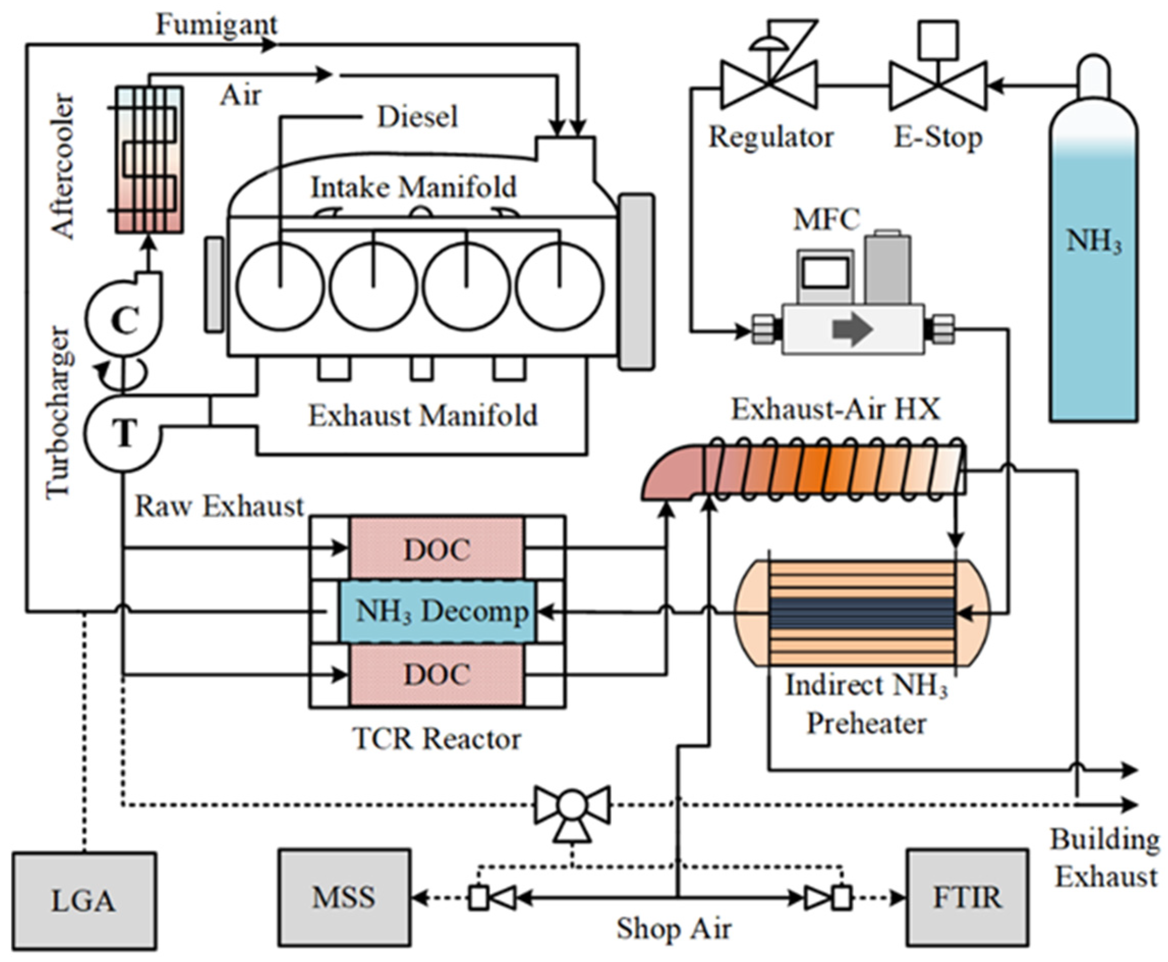
The experimental apparatus including the engine, TCR reactor, and instrumentation used to measure emissions from the system is shown in Figure 1. The TCR consisted of a counter-flow catalytic heat exchanger with a supported precious metal ammonia decomposition catalyst in the center section of each catalyst module and a diesel oxidation catalyst (DOC) in the periphery. Unburned fuel species including total hydrocarbons (THC) and ammonia were oxidized over the DOC, resulting in additional heat from the exothermic reaction. Both sensible heat from the post-turbine exhaust and the chemical energy from oxidation provided heat for endothermic ammonia decomposition. High exhaust temperatures and a high concentration of unburned fuel have the effect of increasing conversion on the ammonia decomposition side of the TCR reactor. The resulting increase in fumigated hydrogen improves combustion efficiency, which decreases unburned species and increases the exhaust temperature. The reactor thus incorporates a beneficial feedback loop to both increase the ammonia fuel percentage compared to diesel and lower post-reactor emissions of ammonia into the environment.

Figure 1.
Experimental schematic for ammonia–diesel dual fuel with TCR. Solid lines are bulk mass flows through the engine, and dashed lines are sampling ports.
Details of the TCR reactor design are presented in Figure 2. The reactor consisted of four catalyst modules arranged in parallel. Each catalyst module used brazed metallic monolith substrates (Metallic Substrates Inc., Coppell, TX, USA) for the DOC and ammonia decomposition sections brazed to a common mantle for enhanced heat transfer. The inner section that contained the ammonia decomposition catalyst was 63.5 mm in diameter and had a cell density of 600 cells per square inch (CPSI). The outer DOC section was 127 mm in diameter with a 300 CPSI cell density. Both sections were 127 mm long. The decomposition catalyst consisted of 4.76% ruthenium by weight on an alumina support wash coated on the metal substrate by Johnson Matthey PLC (Reading, UK). The decomposition catalyst had a 100 mg/cm3 loading. For the DOC, a proprietary platinum-containing combustion catalyst, AB163, wash coated by Johnson Matthey PLC was used. The gas hourly space velocity (GHSV) of the DOC ranged from 40,000 to 130,000 hr−1 over the range of tested conditions. This range is similar to production DOCs used in diesel engine applications [45]. The GHSV range for the ammonia decomposition reactor ranged from 400 to 24,000 hr−1 (4–240 NL/gcat-hr) and was in alignment with similar reactors found in the literature [13,46,47,48].
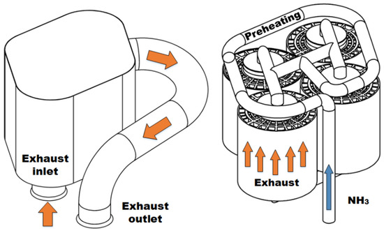
Figure 2.
Shell of reactor assembly with inlet flange and outlet pipe with flange (left). Close-packed arrangement of four catalyst modules shown with preheat loop and manifold (right). Interstitial spaces contain welded flanges to prevent exhaust bypass.
Heat recovery and vaporized ammonia preheating were accomplished using two stages of heat exchange before the decomposition catalyst section of the TCR reactor. An unmodified John Deere EGR cooler (Part RE535729) was utilized for gas–gas exchange between ammonia and the post-reactor exhaust. After leaving the first stage, the heated ammonia flowed into a coiled pipe within the downstream exhaust within the reactor where it was bathed in hot exhaust gas on the outlet side of the DOC section of the TCR reactor. The hot ammonia then flowed directly into the decomposition catalysts, where it flowed counter to the exhaust in the DOC and used the exothermic heat and sensible heat to drive the endothermic decomposition reaction. At the exit of the reactor, the partially decomposed ammonia flowed through several meters of pipe which cooled the mixture before it was fumigated into the intake manifold after the turbocharger aftercooler. The intake manifold temperature was controlled to 45 ± 13 °C throughout the experiments, with variation due primarily to change in engine loading.
The engine used in this work was a John Deere 4045HF475 diesel engine with a Tier 2 off-highway emissions certification. It operated with a stock electronic control unit (ECU) calibration and was loaded using a Dyne Systems AC dynamometer with an in-line torque meter. Additional engine details are reported in Table 1. Gaseous exhaust emissions were measured using an AVL SESAM i60 Fourier transform infrared (FTIR) analyzer with an added paramagnetic oxygen sensor for excess O2 measurement and a flame ionization detector (FID) for THC. Exhaust gas was sampled before and after the exhaust side of the TCR to quantify the efficacy of the DOC in oxidizing unburned fuel species and the chemical enthalpy available for heat recovery. Exhaust soot emissions were measured using an AVL Micro-Soot Sensor (MSS) which quantified the total mass concentration of the soot. The percentage of converted ammonia on the decomposition side of the TCR reactor was measured using an ARI Raman laser gas analyzer (RLGA). Conversion of ammonia was calculated using the measured diatomic hydrogen and nitrogen concentration after the TCR reactor and the known input ammonia mass flow rate. The remaining fraction of the gas was assumed to be ammonia as no other stable gaseous species could thermodynamically result from the dissociation reaction. The RLGA was tested for cross-sensitivity to ammonia and showed no spectrum cross-sensitivity at any concentration.

Table 1.
Specifications of the off-highway diesel engine used in the experimental work.
Engine intake air mass flow was measured using a laminar flow element, and the fuel flow rate was measured using a Brooks Instruments Oval II positive-displacement gear meter. In-cylinder pressure was measured in all four cylinders using Kistler Type 6065A pressure transducers, which were installed using Kistler Type 6542Q128 glow plug adapters. Engine speed was measured using a BEI H25 optical encoder with 0.1 crank angle degree resolution. In-cylinder pressure data were both synchronized to the crank angle position as measured by the encoder and processed using an in-house National Instruments (NI) LabVIEW high-speed acquisition program. The apparent rate of heat release (ARoHR) was determined using in-cylinder pressure measured over 100 consecutive engine cycles using an internally developed function written in the MATLAB programming environment. The first-law approach outlined in Heywood [49] was used to determine ARoHR, and in-cylinder heat transfer was accounted for using the Woschni correlation [50]. Low-speed data including pressures, temperatures, and engine speed and loading were also acquired and processed using a separate National Instruments SCXI-1100 data acquisition system.
Ammonia flow was controlled using a Sierra Instruments (Monterey, CA, USA) C100 mass flow controller. Relevant properties of the three fuels used in this study are reported in Table 2. Liquified ammonia cylinders were sourced from Airgas Specialty Products with a measured purity of 99.995%. Water was the main contaminant in the ammonia cylinders. Number 2 ultra-low sulfur diesel (ULSD) was used as the primary fuel. Diesel fuel properties were determined using independent fuel analysis performed by Paragon Laboratories (Livonia, MI, USA). Hydrogen gas is the primary decomposition product of ammonia in the integrated reactor and was thus included for comparison purposes.
Table 2.
Fuel properties relevant to this work.
Experimental engine operating modes were derived from the ISO 8178 C1 off-road 8-mode test cycle, otherwise known as the non-road steady cycle [52]. The idle condition of the 8-mode test was not examined as exhaust temperatures were not sufficient to decompose ammonia in the TCR reactor. The modes tested in this study are reported in Table 3, with speeds and loads corresponding to the engine-specific values of the 8178-C1 test. Each load is represented as the brake mean effective pressure (BMEP) as measured using brake torque from the dynamometer and the total fuel flow rate.
Table 3.
Engine speed and load conditions used in the experimental study.
At each mode, the engine was brought to steady-state operation using diesel fuel alone determined by the coolant temperature reaching greater than 70 °C and showing less than 1 °C variation over 5 min. Data were then collected at each condition over 60 s intervals, once for exhaust species pre-DOC, and a second time for post-DOC with 60 s between to allow sample lines to be purged of residual species. After sampling at both DOC locations for diesel-only operation, ammonia fumigant was introduced and increased in 5% increments until approximately 50% of diesel fuel energy was replaced with ammonia. The ammonia fuel fraction (AFF) is defined by Equation (2), where is the lower heating value (LHV) of species i, and is the mass flow rate of fuel species i.
The ammonia flow rate at each AFF was calculated using the diesel-only fuel rates and did not account for effects of inefficient combustion or thermochemically recovered energy. Therefore, actual reported replacement rates differ from the expected 5% intervals. For high output modes with high total fuel consumption, ammonia replacement rates were limited to the maximum flow of the mass flow controller.
Measurement uncertainty was calculated as one standard deviation of the measurement for each steady-state condition. Experimental uncertainty in each calculated value was determined using the standard error propagation method. Calculation uncertainty across repeated test conditions was estimated using the steady-state calculation uncertainty combined with weighted repeatability error arising from each experimental replicate. Error bars in figures correspond to the root mean square of one standard deviation from the mean of the total samples taken for that particular test condition.
3. Results and Discussion
3.1. Ammonia Thermochemical Recuperator Performance
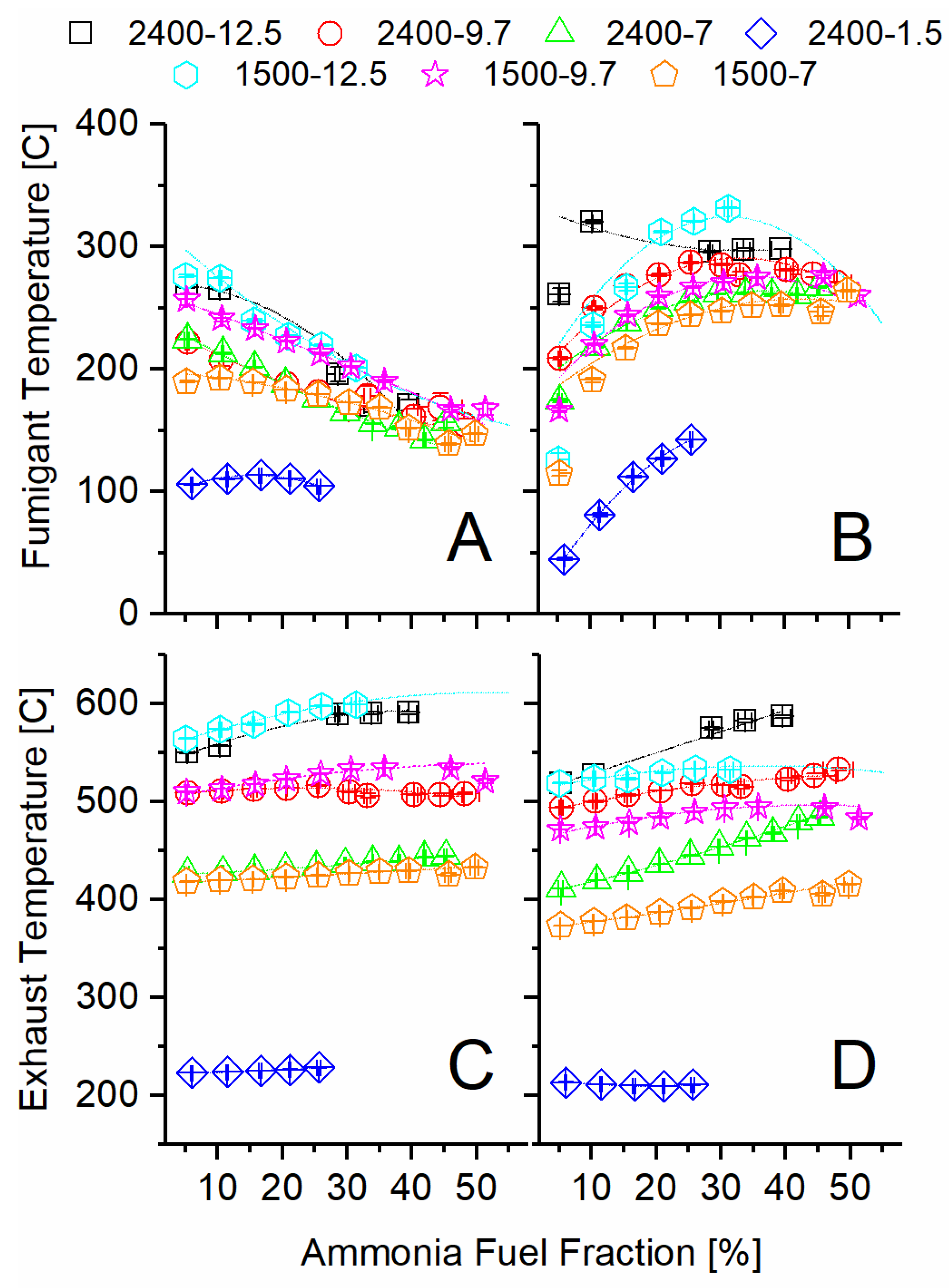
The exhaust temperature after the turbocharger was sufficient to decompose ammonia and produce significant conversion of ammonia to hydrogen in all the tested engine operating modes, except the high-speed, low-load condition (2400 rpm-1.5 bar BMEP). The temperature differences at the two inlets and outlets of the TCR reactor shown in Figure 3 provide an overall view of the sensible energy change for both the ammonia decomposition and DOC sides. As the AFF increased, the ammonia-side inlet temperature decreased sharply for all modes, while the engine exhaust temperature remained constant or increased slightly. The decreased ammonia inlet temperature is evidence that the fuel preheater was not adequate to preheat the ammonia at high flow rates. The increased exhaust temperature at the inlet to the TCR reactor is evidence of lower engine brake thermal efficiency, as will be discussed in the next section.
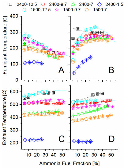
Figure 3.
Recorded temperatures at the inlet and outlet of the ammonia TCR reactor: (A) ammonia side inlet, (B) ammonia side outlet, (C) exhaust side inlet, (D) exhaust side outlet.
Moving from inlet (A) to outlet (B), the ammonia temperature increased significantly through the TCR reactor as the AFF increased. Given that ammonia decomposition is an endothermic reaction, as given in Equation (1), this change confirms significant heat exchange from the exhaust stream to the ammonia reactor. Because the fumigant left the reactor at a higher temperature than it entered but still produced hydrogen, it is evident that the catalyst was active at these temperatures, and additional conversion was possible given a longer residence time. The DOC temperature mostly decreased from inlet (C) to outlet (D) as the AFF increased, showing that heat was effectively transferred to the ammonia side but also lost to the ambient. The magnitude of the temperature decrease is illustrative of residence time impacts on heat transfer and the amount of chemical heat release due to the oxidation over the DOC. For example, the 2400-7 condition showed very little decrease in temperature across the DOC, while the same load at lower speed (1500-7) showed an approximately 30 °C drop over the range of AFFs. Increased residence time at lower engine speed allowed for a greater measured temperature change in the exhaust stream due to both thermochemical recuperation and environmental losses. Despite this, the exhaust temperatures never closely approached the fumigant outlet (B) temperature. This indicated more than sufficient sensible energy was available for additional ammonia decomposition, were it possible using the same reactor.
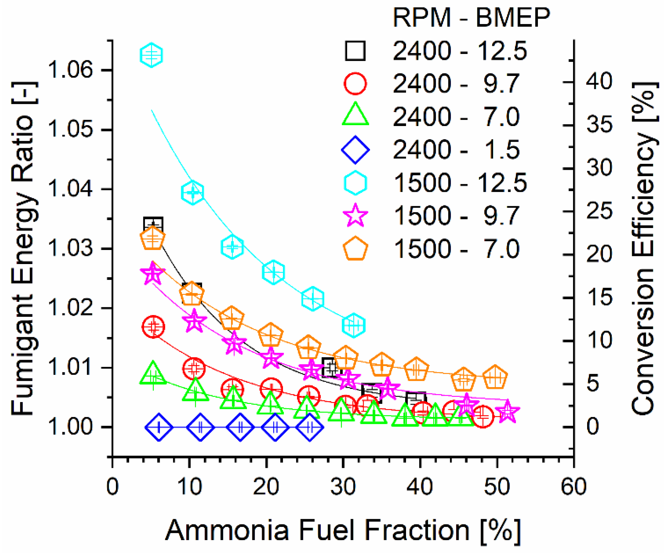
Correlated with decreasing inlet temperature with increasing AFF, Figure 4 shows that TCR reactor ammonia-side conversion efficiency decreased with the AFF for most of the engine modes. Ruthenium catalysts show decomposition activity above 200 °C, with much higher conversion reported at 400 °C or higher [12,35,36,46,53]. Reactor conversion was limited by both temperature and total residence time. Chemical reaction changes the heating value of the fumigated ammonia stream. The energy ratio (ER) is defined as the ratio of the total lower heating value leaving the reactor over the heating value input to the reactor and quantifies this change. Calculation of the ER was performed using Equation (3). The ER is directly proportional to the ammonia decomposition reactor conversion efficiency since the process contains only one primary global reaction. Conversion efficiency was determined using the change in ammonia mass flow through the reactor according to Equation (4). From a thermochemical recovery standpoint, an increased ER leads to an increased heating value. However, a high ER at a low AFF yields less overall engine thermal efficiency benefit since less of the overall fuel stream, including mostly unchanged diesel fuel, is upgraded.
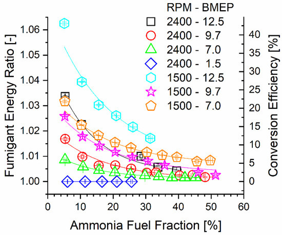
Figure 4.
Fumigant ER and reactor conversion efficiency plotted against engine mode and ammonia fuel fraction.
3.2. Engine Efficiency and Combustion Performance
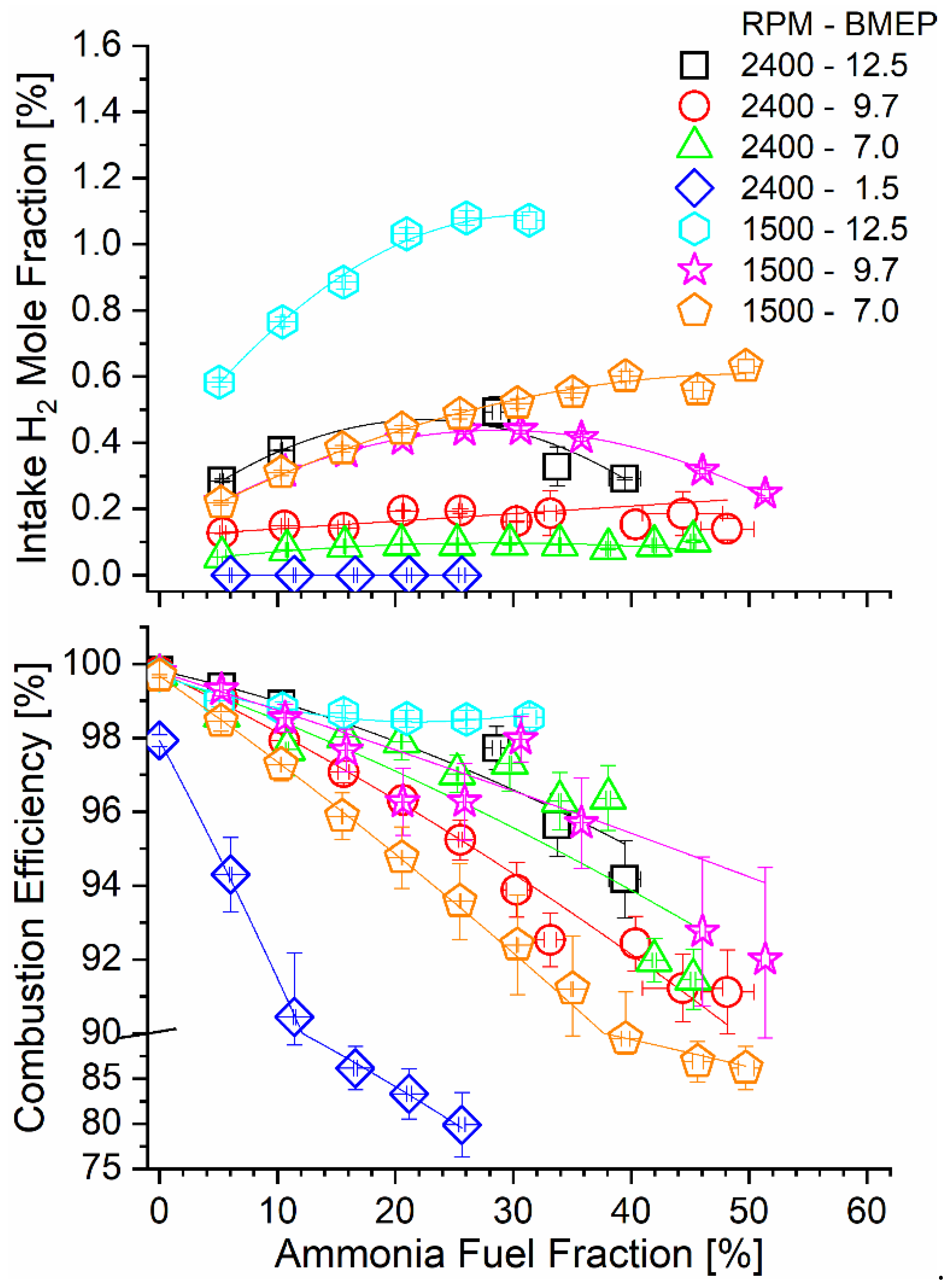
The tradeoff between ammonia conversion through the TCR reactor and the AFF is illustrated qualitatively by the hydrogen mole fraction measured after the ammonia reactor products are mixed with intake air. The intake H2 mole fraction was not directly measured in the experiments but was calculated from the H2 concentration in the reactor exit combined with known engine air and ammonia mass flow rates. As shown in Figure 5, the H2 mole fraction increased with the AFF until a maximum occurred for some engine conditions at the point where poor catalyst conversion overwhelmed increased diesel replacement. The high-speed, low-load condition (2400-1.5) did not produce measurable hydrogen as the conversion efficiency was negligible.
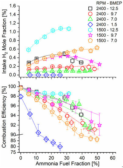
Figure 5.
Intake manifold H2 mole fraction (top) and combustion efficiency (bottom) as a function of engine operating mode and AFF.
Hydrogen in the intake manifold served to enhance combustion of the fumigated ammonia. Combustion efficiency was calculated using steady-state flow rates of combustible species in the engine exhaust, including ammonia and species containing 1–4 carbon atoms. Equation (5) shows this calculation, and the experimental values are reported in Figure 5. Ammonia dual-fuel operation resulted in a sharp decrease in combustion efficiency for all modes, with the most significant decline seen for lower-load modes. Reasons for poor combustion efficiency include positive valve overlap in the tested engine, as has been discussed in our earlier work [44], as well as cold areas of the combustion chamber as in the squish volume, as has been discussed in other dual-fuel engine studies [54,55]. Combustion efficiency declines were mitigated for the increased hydrogen mole fraction in the intake, as can be seen by comparing the bottom and top panels of Figure 5. Low-speed and high-load modes (e.g., 1500-12.5), where ammonia decomposition rates were the highest, benefitted most from an increased hydrogen content during combustion.
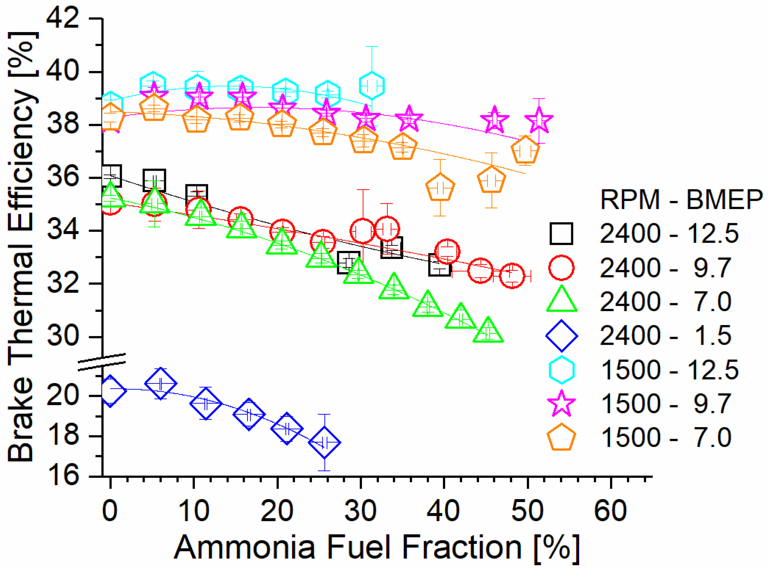
Figure 6 shows engine brake thermal efficiency (BTE) as a function of the AFF and steady-state mode. Trendlines suggest that BTE decreases as the AFF increases. This effect is worsened under high-speed conditions, with the 2400 RPM cases demonstrating the lowest overall BTE at any AFF. At high speed, flame in-cylinder residence is reduced. Decreased flame residence for ammonia results in early combustion quenching and an increased unburned ammonia content. As the AFF increases, the decreased diesel content lowers the flame temperature, resulting in lower diesel combustion efficiency as well. As a result, a higher fueling rate is needed to achieve identical power output, resulting in decreased BTE. The combustion duration at 1500 RPM is 60% longer than at 2400 RPM, which promotes higher combustion efficiency even at a high AFF. Under these conditions, much less fuel is left unburned at exhaust valve open (EVO), and BTE is near baseline. For mode 5 at 1500 RPM and 12.5 Bar BMEP, the measured BTE showed increases under the tested conditions. This was due to the combination of high exhaust temperatures enhancing TCR activity, and the hydrogen from the TCR enhancing ammonia combustion efficiency. Thermochemical waste heat reclamation also decreased the fuel input required, offsetting the effects of ammonia’s poor flame characteristics. This effect is present in other 1500 RPM cases but was only effective at a low AFF, when larger fractions of the fumigant were cracked to hydrogen. Lower engine load resulted in decreased exhaust temperatures and lower conversion rates. As the load decreased, the measured increase in BTE occurred at increasingly lower AFF, with further fumigation becoming detrimental to efficiency. Lastly, consideration must be made regarding the significance of the measured difference. While cases where BTE increased may not have been significantly different, the trends show that BTE can at least be maintained under ammonia fueling for some cases. This alone is important, considering that literature examples of ammonia IC engines typically result in decreasing efficiency.
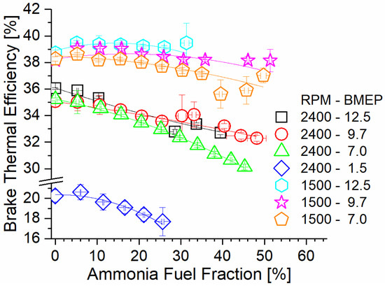
Figure 6.
Brake thermal efficiency versus AFF and engine mode. Low-speed modes show increased efficiency with AFF, and high-speed modes show decreased efficiency.
Operation at 1500 RPM and 12.5 BMEP showed the highest efficiency gain and highest efficiency overall relative to all tested modes. This operating mode also showed the highest measured exhaust temperatures and produced the highest fumigant ER at any rate of the ammonia fuel fraction. Additionally, the hydrogen produced by the recuperation process enhanced ammonia combustion, leading to higher combustion efficiency and greater utilization of the ammonia fuel.
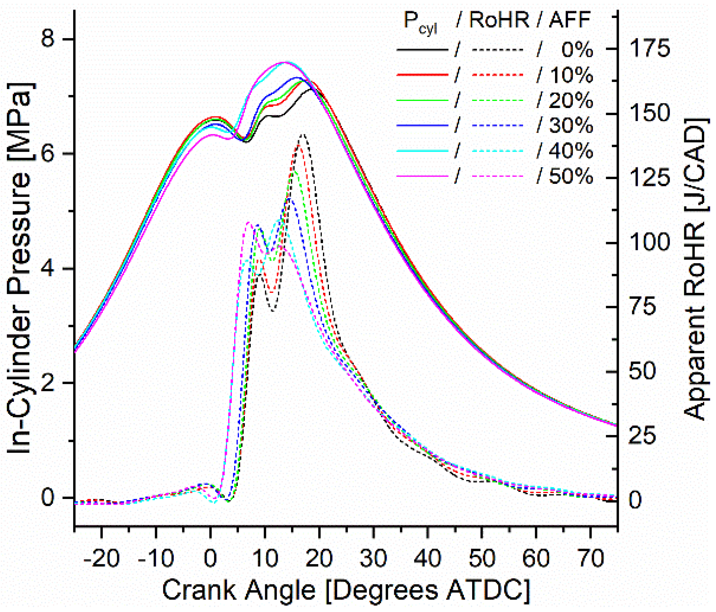
In-cylinder pressure was measured and used to calculate apparent rates of heat release (ARoHR) for all modes. From the heat release calculation, combustion phasing, defined by the crank angle of 50% fuel mass fraction burned (CA50), and combustion duration, defined by the crank angle duration of 10% mass fraction burned to 90% mass fraction burned (CA10-90), were also calculated. For consideration, the onset of combustion (CA10) was also calculated, and all three metrics are reported in the Supplementary Materials. Figure 7 shows the pressure and heat release calculated for mode 6 at 1500 RPM and 9.7 bar BMEP. For all rates of fumigation, ARoHR showed a bimodal release with a primary peak release rate near 10 degrees after top dead center (ATDC) and a secondary peak following before 20 degrees ATDC. For the diesel-only 0% AFF rate, the secondary peak showed a higher ARoHR. As fumigation increased, the secondary ARoHR both decreased and was advanced in timing nearer to top dead center (TDC). The primary peak ARoHR increased as a result and also advanced towards TDC. For the case of other modes, the same phenomenon was observed in which the primary peak ARoHR magnitude increased relative to the secondary, and both peaks advanced towards TDC. However, increasing fumigation was observed to advance combustion phasing only in the case of low-speed modes, and increased in all high-speed modes. Where phasing was advanced, fumigation shifted combustion phasing by up to 2.5 degrees and scaled with the fumigation rate. For phasing that was retarded, up to 3 degrees was calculated and also scaled with the fumigation rate.
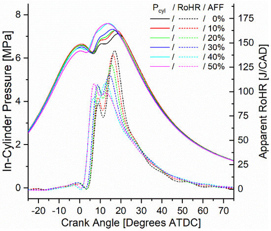
Figure 7.
Mode 6 (1500 RPM, 9.7 Bar BMEP) in-cylinder pressure and ARoHR as a function of engine crank angle and AFF.
The higher ARoHR measured in the initial peak results from shifting the combustion towards a more premixed mode. Less of the fuel mixture is dependent on diffusion and thus initially releases more heat. The added heat release seen here was likely due to the hydrogen fraction of the fumigant. Indeed, the rate at which hydrogen ignited was also likely to shift the peaks of heat release towards TDC, contributing to the first peak while decreasing the delay between the peaks. With the lean conditions of the premixed ammonia and air, the remaining ammonia combustion proceeded slowly following the initial release of heat. Slow ammonia oxidation caused both retarded combustion phasing in the case of high-speed modes and an increase in the combustion duration seen across all modes.
3.3. Engine Emissions
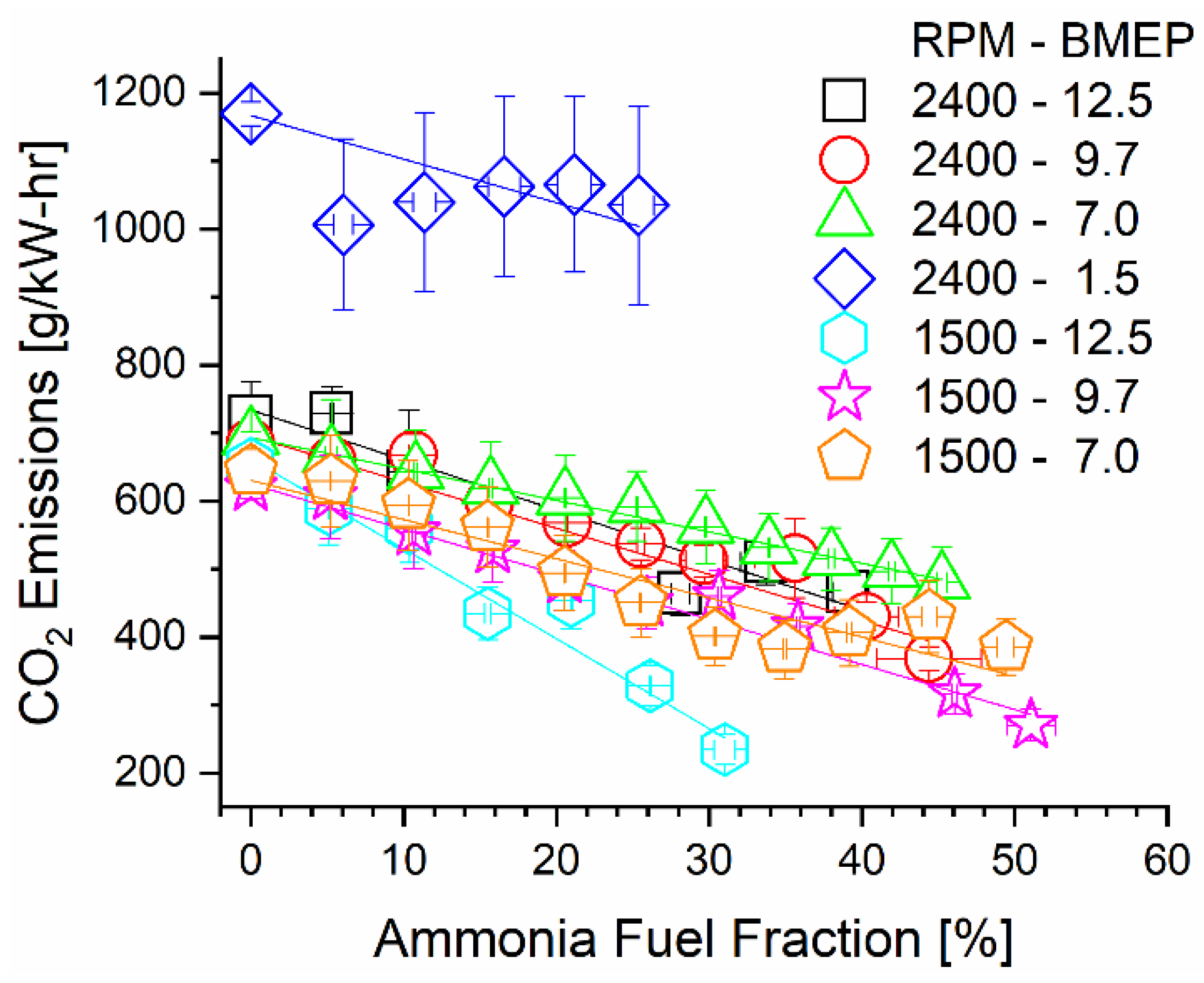
Substitution of diesel fuel energy with carbon-free ammonia drastically decreased carbon dioxide emissions on a brake-specific basis. In addition to the decreased carbon content of the incoming fuel, changes in thermal efficiency appeared to affect brake-specific emission trends. Calculated rates of CO2 emissions are reported in Figure 8 for each mode under varied ammonia fumigation rates. A linear trendline for each mode is also plotted to assist in viewing the emissions change relative to the AFF. Most prominently shown in this figure is the negative-sloped trend of each mode, indicating that CO2 emissions were indeed reduced through fumigation. This was physically expected as thermal efficiency was marginally changed and up to 50% of diesel was replaced with a non-carbon-bearing ammonia fumigant. More interesting is the specific slopes of the modes, particularly the 1500 RPM, 12.5 Bar BMEP, 2400 RPM, 1.5 Bar, and 2400 RPM, 7.0 Bar BMEP modes. The low-speed mode shows the steepest change in emissions, while the two high-speed modes are the most gradual. As carbon was displaced at an equal rate through the AFF, thermal efficiency changes caused this variation in the emissions rate. The decreasing thermal efficiency of most modes partially negates CO2 emissions benefits provided by ammonia, but not enough to prevent CO2 reductions in any case. Affecting positive change in the emissions of combustion engines is the main consideration for ammonia fuel. Based on these calculations, it is imperative to not only displace carbon from fuel but also ensure the fuel energy is extracted efficiently to create maximum benefit.

Figure 8.
Brake-specific CO2 emissions as a function of engine speed, load, and AFF.
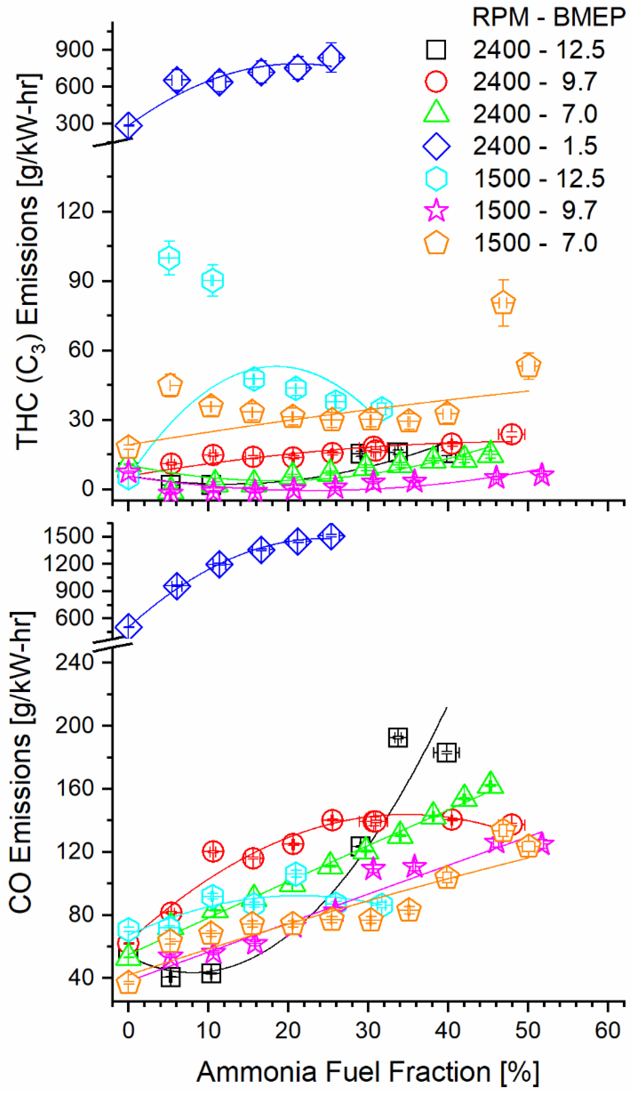
Ammonia fumigation decreased combustion efficiency, thus increasing carbon monoxide (CO) and THC emissions. It is counterintuitive that decreasing the hydrocarbon fuel fraction would increase emissions of gaseous carbon species, but the observation can be explained by ammonia’s effect on the diffusive combustion. When ammonia is mixed with air and is inducted to the cylinder, there exists a charge of premixed fuel and air. When diesel is injected into the cylinder and ignited, the diesel diffusion flame can consume fuel on both the diesel and oxidizer sides. This increases the local equivalence ratio of the flame, permitting survival of secondary fuel species produced by diesel combustion. If the residence time in the cylinder is short enough that the flame is quenched before these species oxidize, they are exhausted without reacting. Figure 9 shows the clear increasing trend in both CO and THC emissions as fumigation increases for most modes. The 1500 RPM, 12.5 BMEP case shows a decrease in THC at the maximum tested fumigation but increases for all other AFFs. Operation at 1500 RPM and 9.7 BMEP showed the opposite trend, with an initial sharp decrease in THC, followed by a gradual increase towards baseline.
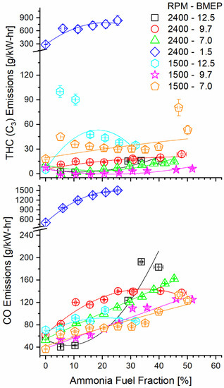
Figure 9.
Brake-specific THC and CO emissions as a function of mode and AFF as measured post-DOC. Ammonia fumigation increased emissions of these carbon species, despite a decrease in hydrocarbon fueling.
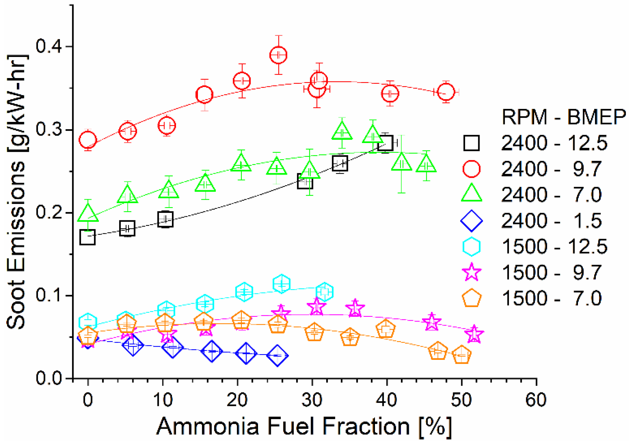
As shown in Figure 10, soot emissions remained constant or slightly increased with the increase in the ammonia AFF. The increased local equivalence ratio promoted soot production by preventing oxygen access. As previously shown, ammonia fumigation leads to an increased combustion duration and lower flame temperatures. The higher AFF thus both decreased global combustion temperatures and limited post-diffusion flame soot oxidation. High-speed and load operating conditions had the highest brake-specific soot emissions due to higher fuel flow rates and the shorter residence time.
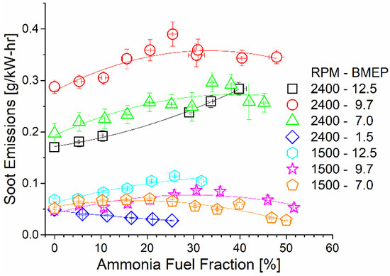
Figure 10.
Soot emissions as a function of mode and AFF. Soot tended to increase or remain constant as ammonia fumigation was increased, despite the decreased diesel fueling rate.
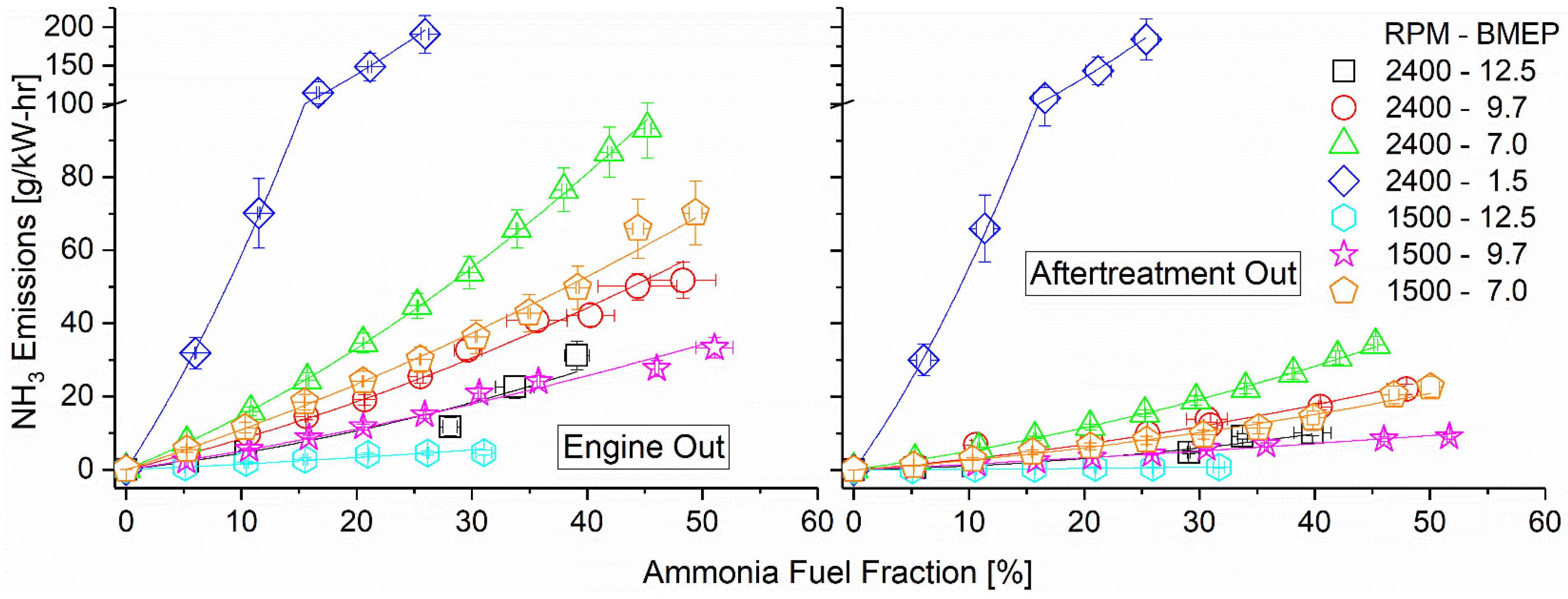
Ammonia emissions both pre- and post-DOC are shown in Figure 11 as they vary with engine mode and fumigation rate. Due to ammonia’s poor combustion characteristics, unburned emissions remained high across all tested modes. The highest emissions pre-DOC were found to correspond with lower engine loads, which featured cooler combustion temperatures. Ammonia oxidation kinetics are very slow compared to hydrocarbons such as diesel and benefit from the increased temperature. Operating at 1500 RPM and 12.5 bar BMEP showed the lowest unburned ammonia emissions as a direct result of its high combustion temperature and high-intake hydrogen fraction. The addition of hydrogen assisted in promoting ammonia combustion, increasing combustion efficiency, and thus lowering emissions. As intake hydrogen depended directly on exhaust temperatures in the reactor, the main driving force of ammonia emissions was thus the combustion temperature. Post-DOC, ammonia emissions were reduced by approximately 50%, showing effective and consistent elimination by the DOC. Emissions rates show roughly the same trends as the pre-DOC measurements, indicating that variations in the temperature and exhaust equivalence ratio across the tested modes were not important factors in the elimination efficiency.

Figure 11.
Ammonia emissions pre-DOC (left) and post-DOC (right). Ammonia oxidized on the DOC, converting to NOx. Ammonia emissions were reduced by approximately half by the DOC. Concentrations in ppm available in Supplementary Materials.
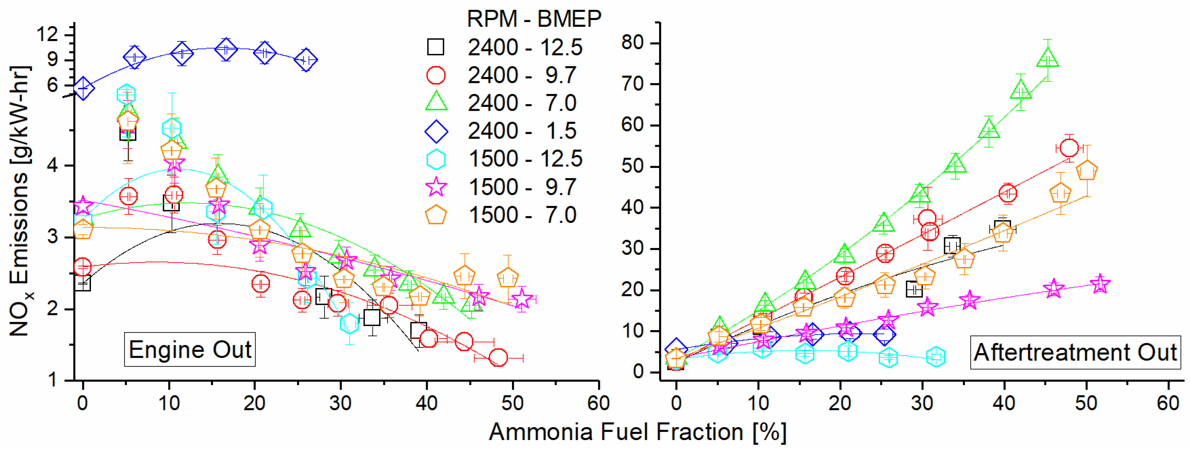
Figure 12 depicts the engine NOx emissions as a function of the mode and AFF, measured both before and after the DOC. NOx shows a decreasing trend across all modes before the DOC and is a direct result of a shift towards cooler premixed combustion. The ammonia fumigant was premixed with intake air and served to decrease localized hot spots caused by diesel combustion. This decreased thermal NOx generation, offsetting any fuel NOx formed by the combustion of ammonia. Engine operation at 2400 RPM and 1.5 Bar BMEP showed little change in brake-specific NOx output as a result of fumigation, likely due to the already lean and cool combustion in this low-load mode. What little thermal NOx was formed may decrease with fumigation, but this does not offset that which was introduced by fuel NOx. For several modes, there is an increase in or leveling off of NOx at a higher AFF. At these points, increased ammonia must be causing additional fuel NOx, but there is diminishing benefit of premixed combustion on thermal NOx production. Added ammonia thus increases NOx production after a point. Post-DOC, NOx was found to increase by one–two orders of magnitude for each mode. This was caused by unburned ammonia oxidation over the DOC. The lean exhaust is not conducive to NOx reduction by fuel species, and the DOC formulation did not promote selective catalytic reduction (SCR) of the NOx by ammonia. The result was that ammonia emissions were reduced but were converted to another pollutant species instead of reducing the overall pollutant concentration in the exhaust.
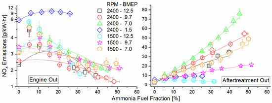
Figure 12.
Engine NOx emission for both pre-DOC (left) and post-DOC (right) as a function of mode and AFF. Pre-DOC NOx shows decreasing trend with increased ammonia fumigation. Post-DOC NOx shows drastic increase due to selective ammonia oxidation on the catalyst.
Figure 13 shows brake-specific N2O emissions at the engine-out location and total emissions post-DOC. Pre-DOC, we see an increase in combustion-derived N2O, with the higher-temperature modes actually showing a decreasing trend after the initial increase for the higher AFF. In the post-DOC results, all modes except 1500 RPM, 12.5 bar BMEP show an increase in N2O from their pre-DOC levels, with a particularly sharp increase in the lower-load modes (2400 RPM, 7.0 and 1.5 bar BMEP, and 1500 RPM, 7.0 BMEP). In the case of operation at 1500 RPM, 12.5 BMEP, N2O decreases through the DOC.
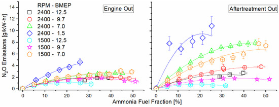
Figure 13.
Engine-out (left) and DOC-out (right) exhaust emissions of nitrous oxide as a function of mode and AFF. Increased ammonia fumigation increased N2O emissions, but unburned ammonia reactions within the DOC generated far greater nitrogen emissions than engine combustion.
Ammonia combustion and subsequent oxidation within the after-treatment catalyst produced undesirable oxides of nitrogen, but residual ammonia remained in the exhaust stream post-catalyst. As ammonia is useful for the reduction of NOx and N2O, selective catalytic reduction could be employed to eliminate both species simultaneously downstream of the primary after-treatment catalyst. The ratio of ammonia to NOx molecules in the exhaust can be defined as the alpha ratio. A study by Girard et al. [56] showed that ideal elimination of both species occurs when alpha is near unity, but preferential elimination of one species over the other can be obtained by varying the alpha ratio higher or lower than unity. The alpha ratio of each test condition is reported in Figure 14 as a function of the ammonia AFF and engine mode. For all points aside from the 2400 rpm, 1.5 bar case, the exhaust ratio is below unity. Assuming a similar behavior to that of Girard et al., utilization of SCR downstream of the oxidation catalyst could eliminate most ammonia emissions while simultaneously eliminating substantial NOx. Additionally, exhaust temperatures were shown earlier to be sufficient post-DOC to achieve the activity reported in Girard et al. The concentrations of both species are much higher in this study than those found in Girard et al., which would likely improve SCR activity at a given temperature. Finally, it was shown that the oxidation catalyst in this study produced a significant fraction of the NOx measured post-DOC from engine-out ammonia. Based on this, it is reasonable to suggest that ammonia and NOx emissions could be eliminated more completely if the after-treatment catalyst(s) were modified to include an SCR formulation instead of a conventional DOC. A combination of an ammonia oxidation catalyst and an SCR catalyst could control the rate of ammonia oxidation such that the downstream SCR process is always ideal for ammonia and NOx elimination. If integrated into this study’s reactor, the additional heat released by the passive SCR would enhance the ammonia decomposition reaction and improve both efficiency and operability.
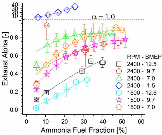
Figure 14.
Exhaust alpha ratio as a function of engine mode and AFF. Alpha ratio of unity is shown using a dashed line which coincides with the ordinate axis scale change.
4. Conclusions
This work presented experimental results from a compression ignition engine equipped with a thermochemical recuperation reactor that reclaimed exhaust energy to feed an ammonia decomposition catalyst. The reactor was able to increase the fraction of ammonia versus diesel fuel compared to previous studies, as well as decreasing the amount of unburned ammonia in the exhaust stream. The measured brake thermal efficiency was improved for low-speed modes when ammonia fumigation increased. Higher loading produced the greatest benefit, with measured BTE gains occurring under the highest-load case. High-speed modes showed a decrease in efficiency, with efficiency dropping due to both lowering engine loading and adding the ammonia fumigant. High loading was shown to increase available intake hydrogen, which prevented the combustion efficiency from decreasing and maintained high thermal efficiency. Heat release calculations revealed that combustion phasing advanced with low-speed modes and retarded with high-speed modes. Advancement of combustion phasing would have allowed BTE gains under low-speed conditions, but the simultaneous combustion duration increase with fumigation would have produced the opposite effect. Together, these effects resulted in a negligible BTE change under the best observed conditions, and a negative change under all others.
Carbon dioxide emissions were decreased for all modes due to the lack of chemical carbon in ammonia fuel. However, THC and NOx emissions were shown to increase. As expected, direct ammonia combustion resulted in substantial unburned ammonia emissions, but combustion efficiency remained above 90% for most modes. Ammonia emissions were partially eliminated by the DOC in the TCR reactor but produced additional NOx as opposed to N2. At the DOC outlet, both NOx and ammonia were present in similar concentrations to those used in SCR, indicating a passive solution to eliminate both pollutants simultaneously. N2O was also measured to increase due to ammonia combustion and unburned ammonia oxidation within the DOC. DOC-generated N2O was more substantial of the two sources and could be mitigated with a reformulation of the catalyst. Engine-emitted N2O could be decreased by greater ammonia decomposition activity before combustion, eliminating the potential for both fuel NOx and fuel N2O.
A practical implementation of ammonia dual fuel need not use static replacement rates such as those demonstrated in this work. Emissions and engine measurements clearly showed that each mode had replacement rates which yielded the greatest efficiency, emissions, or both. For some modes, the optimum point may be CDC. Practical implementation might consist of mapping fumigation to correspond with only a range of operating modes, in order to avoid decreasing engine performance. To do this would make more efficient use of ammonia fuel, maximizing energy recovery, engine efficiency, and emissions benefits for a given reactor–engine combination. As the replacement rate can be varied under steady load without affecting engine stability or output, a dynamic AFF map would represent a useful tool for any ammonia–diesel application.
Supplementary Materials
The following are available online at https://www.mdpi.com/article/10.3390/en14227540/s1, Table S1: Supplementary engine operating conditions and outcomes.
Author Contributions
Methodology, all authors; formal analysis and investigation, S.P.K.; resources, all authors; writing—original draft preparation, S.P.K.; writing—review and editing, all authors; project administration and funding acquisition, W.F.N. All authors have read and agreed to the published version of the manuscript.
Funding
This project was sponsored by the Legislative Citizen Commission on Minnesota Resources under the Minnesota Legislature 2016 Environment and Natural Resources Trust Fund (ENRTF), Chp. 186, Sec. 2, Subd. 07c.
Institutional Review Board Statement
Not applicable.
Informed Consent Statement
Not applicable.
Acknowledgments
The authors would like to thank Andrew York, and David Wails of Johnson Matthey, PLC, for providing and coating the catalysts used in this project.
Conflicts of Interest
The authors declare no conflict of interest.
References
- Solomon, S.; Plattner, G.; Knutti, R.; Friedlingstein, P. Irreversible climate change due to carbon dioxide emissions. Proc. Natl. Acad. Sci. USA 2009, 106, 1704–1709. [Google Scholar] [CrossRef] [Green Version]
- Schmale, J.; Flanner, M.; Kang, S.; Sprenger, M.; Zhang, Q.; Guo, J.; Li, Y.; Schwikowski, M.; Farinotti, D. Modulation of snow reflectance and snowmelt from Central Asian glaciers by anthropogenic black carbon. Sci. Rep. 2017, 7, 40501. [Google Scholar] [CrossRef]
- Schwarz, J.P.; Gao, R.S.; Perring, A.E.; Spackman, J.R.; Fahey, D.W. Black carbon aerosol size in snow. Sci. Rep. 2013, 3, 1356. [Google Scholar] [CrossRef] [PubMed]
- Sacks, J.; Kirrane, E.; Luben, T.; Oesterling Owens, E. Provisional Assessment of Recent Studies on Health Effects of Particulate Matter Exposure; EPA/600/R-12/056; U.S. Environmental Protection Agency: Washington, DC, USA, 2012; p. 65.
- Moradi, R.; Groth, K.M. Hydrogen storage and delivery: Review of the state of the art technologies and risk and reliability analysis. Int. J. Hydrogen Energy 2019, 44, 12254–12269. [Google Scholar] [CrossRef]
- Ummary, S. Renewable Energy to Fuels through Utilization of EnergyDense Liquids (REFUEL) Program Overview. Available online: https://arpa-e.energy.gov/sites/default/files/documents/files/REFUEL_ProgramOverview_FINAL.pdf (accessed on 21 September 2021).
- Chisalita, D.A.; Petrescu, L.; Cormos, A.M.; Cormos, C.C. Assessing Energy and CO2 Emission Reduction from Ammonia Production by Chemical Looping as Innovative Carbon Capture Technology. In Proceedings of the 28th European Symposium on Computer Aided Process Engineering, Graz, Austria, 10–13 June 2018; Elsevier B.V.: Graz, Austria, 2018; Volume 43, pp. 1269–1274. [Google Scholar]
- International Fertilizer Industry Association. Fertilizers, Climate Change and Enhancing Agricultural Productivity Sustainably; International Fertilizer Industry Association: Paris, France, 2009; pp. 1–30. [Google Scholar]
- Wang, L.; Xia, M.; Wang, H.; Huang, K.; Qian, C.; Maravelias, C.T.; Ozin, G.A. Greening Ammonia toward the Solar Ammonia Refinery. Joule 2018, 2, 1055–1074. [Google Scholar] [CrossRef] [Green Version]
- Reese, M.; Marquart, C.; Malmali, M.; Wagner, K.; Buchanan, E.; McCormick, A.; Cussler, E.L. Performance of a Small-Scale Haber Process. Ind. Eng. Chem. Res. 2016, 55, 3742–3750. [Google Scholar] [CrossRef]
- Thomas, G.; Parks, G. Potential Roles of Ammonia in a Hydrogen Economy. Energy 2006, 1–23. [Google Scholar]
- Comotti, M.; Frigo, S. Hydrogen generation system for ammonia-hydrogen fuelled internal combustion engines. Int. J. Hydrogen Energy 2015, 40, 10673–10686. [Google Scholar] [CrossRef]
- Wang, W.; Herreros, J.M.; Tsolakis, A.; York, A.P.E. Ammonia as hydrogen carrier for transportation; Investigation of the ammonia exhaust gas fuel reforming. Int. J. Hydrogen Energy 2013, 38, 9907–9917. [Google Scholar] [CrossRef] [Green Version]
- Kobayashi, H.; Hayakawa, A.; Somarathne, K.D.K.A.K.A.; Okafor, E.C. Science and technology of ammonia combustion. Proc. Combust. Inst. 2019, 37, 109–133. [Google Scholar] [CrossRef]
- Reiter, A.J.; Kong, S.C. Combustion and emissions characteristics of compression-ignition engine using dual ammonia-diesel fuel. Fuel 2011, 90, 87–97. [Google Scholar] [CrossRef] [Green Version]
- Reiter, A.J.; Kong, S.C. Demonstration of compression-ignition engine combustion using ammonia in reducing greenhouse gas emissions. Energy Fuels 2008, 22, 2963–2971. [Google Scholar] [CrossRef]
- Frigo, S.; Gentili, R. Analysis of the behaviour of a 4-stroke Si engine fuelled with ammonia and hydrogen. Int. J. Hydrogen Energy 2013, 38, 1607–1615. [Google Scholar] [CrossRef]
- Liu, R.; Ting, D.S.K.; Checkel, M.D. Ammonia as a fuel for SI engine. SAE Tech. Pap. 2003, 1. [Google Scholar] [CrossRef]
- Gill, S.S.; Chatha, G.S.; Tsolakis, A.; Golunski, S.E.; York, A.P.E. Assessing the effects of partially decarbonising a diesel engine by co-fuelling with dissociated ammonia. Int. J. Hydrogen Energy 2012, 37, 6074–6083. [Google Scholar] [CrossRef]
- Updyke, K.M.; Nguyen, T.B.; Nizkorodov, S.A. Formation of brown carbon via reactions of ammonia with secondary organic aerosols from biogenic and anthropogenic precursors. Atmos. Environ. 2012, 63, 22–31. [Google Scholar] [CrossRef]
- Behera, S.N.; Sharma, M. Investigating the potential role of ammonia in ion chemistry of fine particulate matter formation for an urban environment. Sci. Total Environ. 2010, 408, 3569–3575. [Google Scholar] [CrossRef]
- Wang, S.; Nan, J.; Shi, C.; Fu, Q.; Gao, S.; Wang, D.; Cui, H.; Saiz-Lopez, A.; Zhou, B. Atmospheric ammonia and its impacts on regional air quality over the megacity of Shanghai, China. Sci. Rep. 2015, 5, 15842. [Google Scholar] [CrossRef] [Green Version]
- Johnson, T.; Joshi, A. Review of Vehicle Engine Efficiency and Emissions. SAE Int. J. Engines 2018, 11, 1307–1330. [Google Scholar] [CrossRef]
- Otomo, J.; Koshi, M.; Mitsumori, T.; Iwasaki, H.; Yamada, K. Chemical kinetic modeling of ammonia oxidation with improved reaction mechanism for ammonia/air and ammonia/hydrogen/air combustion. Int. J. Hydrogen Energy 2018, 43, 3004–3014. [Google Scholar] [CrossRef]
- Shrestha, K.P.; Seidel, L.; Zeuch, T.; Mauss, F. Detailed Kinetic Mechanism for the Oxidation of Ammonia Including the Formation and Reduction of Nitrogen Oxides. Energy Fuels 2018, 32, 10202–10217. [Google Scholar] [CrossRef]
- U.S. Environmental Protection Agency (EPA). Inventory of U.S. Greenhouse Gas Emissions and Sinks: 1990–2016; EPA: Washington, DC, USA, 2018.
- Haputhanthri, S.O. Ammonia Gasoline Fuel Blends: Feasibility Study of Commercially Available Emulsifiers and Effects on Stability and Engine Performance. SAE Tech. Pap. 2014. [Google Scholar] [CrossRef]
- Grannell, S.M.; Assanis, D.N.; Bohac, S.V.; Gillespie, D.E. The Fuel Mix Limits and Efficiency of a Stoichiometric, Ammonia, and Gasoline Dual Fueled Spark Ignition Engine. J. Eng. Gas Turbines Power 2008, 130, 042802. [Google Scholar] [CrossRef]
- Tay, K.L.; Yang, W.; Chou, S.K.; Zhou, D.; Li, J.; Yu, W.; Zhao, F.; Mohan, B. Effects of Injection Timing and Pilot Fuel on the Combustion of a Kerosene-diesel/Ammonia Dual Fuel Engine: A Numerical Study. Energy Procedia 2017, 105, 4621–4626. [Google Scholar] [CrossRef]
- Frigo, S.; Gentili, R.; De Angelis, F. Further Insight into the Possibility to Fuel a SI Engine with Ammonia plus Hydrogen. SAE Tech. Pap. 2014, 1. [Google Scholar] [CrossRef]
- Boretti, A. Novel dual fuel diesel-ammonia combustion system in advanced TDI engines. Int. J. Hydrogen Energy 2017, 42, 7071–7076. [Google Scholar] [CrossRef]
- NIOSH. Pocket Guide to Chemical Hazards. Available online: https://www.cdc.gov/niosh/npg/ (accessed on 21 September 2021).
- Pozzana, G.; Bonfanti, N.; Frigo, S.; Doveri, N.; Dario, P.; Mattoli, V.; Ragnoli, M. A hybrid vehicle powered by hydrogen and ammonia. SAE Tech. Pap. 2012, 4. [Google Scholar] [CrossRef]
- Pochet, M.; Truedsson, I.; Foucher, F.; Jeanmart, H.; Contino, F. Ammonia-Hydrogen Blends in Homogeneous-Charge Compression-Ignition Engine. SAE Tech. Pap. 2017. [Google Scholar] [CrossRef]
- Hill, A.K.; Torrente-Murciano, L. In-situ H2 production via low temperature decomposition of ammonia: Insights into the role of cesium as a promoter. Int. J. Hydrogen Energy 2014, 39, 7646–7654. [Google Scholar] [CrossRef] [Green Version]
- Hill, A.K.; Torrente-Murciano, L. Low temperature H2 production from ammonia using ruthenium-based catalysts: Synergetic effect of promoter and support. Appl. Catal. B Environ. 2015, 172–173, 129–135. [Google Scholar] [CrossRef] [Green Version]
- Huang, D.C.; Jiang, C.H.; Liu, F.J.; Cheng, Y.C.; Chen, Y.C.; Hsueh, K.L. Preparation of Ru-Cs catalyst and its application on hydrogen production by ammonia decomposition. Int. J. Hydrogen Energy 2013, 38, 3233–3240. [Google Scholar] [CrossRef]
- Plana, C.; Armenise, S.; Monzón, A.; García-Bordejé, E. Ni on alumina-coated cordierite monoliths for in situ generation of CO-free H2 from ammonia. J. Catal. 2010, 275, 228–235. [Google Scholar] [CrossRef]
- Tartakovsky, L.; Sheintuch, M. Fuel reforming in internal combustion engines. Prog. Energy Combust. Sci. 2018, 67, 88–114. [Google Scholar] [CrossRef]
- Fennell, D.; Herreros, J.; Tsolakis, A. Improving gasoline direct injection (GDI) engine efficiency and emissions with hydrogen from exhaust gas fuel reforming. Int. J. Hydrogen Energy 2014, 39, 5153–5162. [Google Scholar] [CrossRef]
- Fennell, D.; Herreros, J.M.; Tsolakis, A.; Xu, H.; Cockle, K.; Millington, P. GDI Engine Performance and Emissions with Reformed Exhaust Gas Recirculation (REGR). SAE Tech. Pap. 2013. [Google Scholar] [CrossRef]
- Lau, C.S.; Allen, D.; Tsolakis, A.; Golunski, S.E.; Wyszynski, M.L. Biogas upgrade to syngas through thermochemical recovery using exhaust gas reforming. Biomass Bioenergy 2012, 40, 86–95. [Google Scholar] [CrossRef]
- Hwang, J.T.; Kane, S.P.; Northrop, W.F. Demonstration of Single-Fuel Reactivity Controlled Compression Ignition Using Reformed Exhaust Gas Recirculation. SAE Tech. Pap. 2018. [Google Scholar] [CrossRef]
- Hwang, J.T.; Kane, S.P.; Northrop, W.F. Hydrous Ethanol Steam Reforming and Thermochemical Recuperation to Improve Dual-Fuel Diesel Engine Emissions and Efficiency. J. Energy Resour. Technol. Trans. ASME 2019, 141, 112203. [Google Scholar] [CrossRef]
- Northrop, W.F.; Assanis, D.; Bohac, S. Evaluation of Diesel Oxidation Catalyst Conversion of Hydrocarbons and Particulate Matter from Premixed Low Temperature Combustion of Biodiesel. SAE Int. J. Engines 2011, 4, 1431–1444. [Google Scholar] [CrossRef]
- Di Carlo, A.; Vecchione, L.; Del Prete, Z. Ammonia decomposition over commercial Ru/Al2O3 catalyst: An experimental evaluation at different operative pressures and temperatures. Int. J. Hydrogen Energy 2014, 39, 808–814. [Google Scholar] [CrossRef]
- Yin, S.F.; Xu, B.Q.; Wang, S.J.; Au, C.T. Nanosized Ru on high-surface-area superbasic ZrO2-KOH for efficient generation of hydrogen via ammonia decomposition. Appl. Catal. A Gen. 2006, 301, 202–210. [Google Scholar] [CrossRef]
- Chiuta, S.; Everson, R.C.; Neomagus, H.W.J.P.; Bessarabov, D.G. Hydrogen production from ammonia decomposition over a commercial Ru/Al2O3 catalyst in a microchannel reactor: Experimental validation and CFD simulation. Int. J. Hydrogen Energy 2016, 41, 3774–3785. [Google Scholar] [CrossRef]
- Heywood, J.B.B. Internal Combustion Engine Fundamentals; McGraw-Hill, Inc.: New York, NY, USA, 1988; ISBN 007028637X. [Google Scholar]
- Woschni, G. A Universally Applicable Equation for the Instantaneous Heat Transfer Coefficient in the Internal Combustion Engine. SAE Tech. Pap. 1967, 670931. [Google Scholar] [CrossRef]
- Davisson, L.D. Comments on Potential Roles of Ammonia in a Hydrogen Economy—A Study of Issues Related to the Use ofAmmonia for On-Board Vehicular Hydrogen Storage. Proc. IEEE 2010, 54, 2010. [Google Scholar] [CrossRef]
- ISO Standard 8178-4:2017, Reciprocating Internal Combustion Engines—Exhaust Emission Measurement—Part 4: Steady-State and Transient Test Cycles for Different Engine Applications; ISO: Geneva, Switzerland, 2017.
- Szmigiel, D.; Raróg-Pilecka, W.; Miśkiewicz, E.; Kaszkur, Z.; Kowalczyk, Z. Ammonia decomposition over the ruthenium catalysts deposited on magnesium-aluminum spinel. Appl. Catal. A Gen. 2004, 264, 59–63. [Google Scholar] [CrossRef]
- Königsson, F.; Stalhammar, P.; Angstrom, H.E. Characterization and potential of dual fuel combustion in a modern diesel engine. SAE Tech. Pap. 2011. [Google Scholar] [CrossRef]
- Königsson, F.; Kuyper, J.; Stalhammar, P.; Angstrom, H.E. The Influence of Crevices on Hydrocarbon Emissions from a Diesel-Methane Dual Fuel Engine. SAE Int. J. Engines 2013, 6, 751–765. [Google Scholar] [CrossRef]
- Girard, J.; Snow, R.; Cavataio, G.; Lambert, C. The influence of ammonia to NOX ratio on SCR performance. SAE Tech. Pap. 2007. [Google Scholar] [CrossRef]


Publisher’s Note: MDPI stays neutral with regard to jurisdictional claims in published maps and institutional affiliations. |
© 2021 by the authors. Licensee MDPI, Basel, Switzerland. This article is an open access article distributed under the terms and conditions of the Creative Commons Attribution (CC BY) license (https://creativecommons.org/licenses/by/4.0/).