Article

Experimental Study on Hydroelectric Energy Harvester Based on a Hybrid Qiqi and Turbine Structure

1
Department of Mechanics and Aerospace Engineering, Southern University of Science and Technology, Shenzhen 518055, China
2
Guangdong Provincial Key Laboratory of Durability for Marine Civil Engineering, Shenzhen University, Shenzhen 518060, China
3
Department of Civil and Environmental Engineering, Shantou University, Shantou 515063, China
*
Author to whom correspondence should be addressed.
Energies 2021, 14(22), 7601; https://doi.org/10.3390/en14227601
Submission received: 6 October 2021 / Revised: 1 November 2021 / Accepted: 9 November 2021 / Published: 13 November 2021

Abstract

:
The Qiqi structure design can automatically upset and spill its content once it arrives at limit capacity under vertical water flow excitation. Considering this function, the Qiqi structure has been utilized for small hydroelectric energy harvesting lately. To investigate the tradeoff between the Qiqi structure and the turbine structure for small hydroelectric energy harvesting, an energy harvester based on a hybrid Qiqi and turbine structure is proposed for vertical water flow hydroelectric applications. The hybrid structure is composed of a rectangular Qiqi structure, with two blades inserted on both sides. Self-tipping function of the hybrid Qiqi structure and working principle of the structure is investigated in detail. The proposed structure has both the advantages of low flow velocity energy harvesting of the Qiqi structure and high flow velocity energy harvesting of the turbine structure. A hydroelectric energy harvesting application using the hybrid structure is given to demonstrate that the hybrid structure had a higher rotational speed than the Qiqi structure under vertical low water flow excitation and was able to work at relatively high flow rates. Thus, the investigated hybrid structure can help small rotational hydropower achieve better energy harvesting performance and work at wide-range flow rates under vertical ultra-low water flow applications. At 600 mL/min, 902 μJ of electrical energy was charged by the investigated structure, which is six times higher than that using the Qiqi structure alone.

1. Introduction

Turbine structures [1] are frequently used to extract energy from fluid flow in rotational fluid energy harvesting applications [2,3,4]. Normally, a turbine structure is a turbomachine with at least one rotor assembly. The rotor assembly is a shaft with attached blades. The blades are driven by the moving fluid flow; thus, the mechanical energy of the fluid flow is transformed to the rotational mechanical energy of the turbine structure. The generators finally convert the rotational energy into electrical energy. For hydroelectric energy harvesting [5], there are many physical principles employed by turbines to harvest hydro-energy, such as impulse turbines and reaction turbines. Impulse turbines [6] change the high-velocity fluid flow direction. Accelerating the fluid with a nozzle can change the pressure head to the velocity head before reaching the impulse turbine. Impulse turbines [7] are suitable for applications where the flow is low and the inlet pressure is high. For reaction turbines [8], torque is developed by reacting the pressure or mass of the fluid. Reaction turbines [9] are suitable for higher flow velocities or applications where the fluid head is low. In practical applications, both reaction and impulse concepts are applied to the design of modern turbines in different practical applications.
However, turbine structures are difficult to employ for harvesting fluid energy with ultra-low energy density, such as ultra-low water flow applications with ultra-low hydraulic heads (velocity head, pressure head, and elevation head). Additionally, fluid energy harvesters with blades may have negative effects on wildlife, climate change, and other issues. Therefore, bladeless energy-harvesting structures have been gradually developed. Nikola Tesla patented a Tesla turbine [10], which is a bladeless centripetal flow turbine in 1913. It is called as the boundary-layer turbine as well [11] because it does not use a fluid to impact the blades, as in a traditional turbine but, rather, the boundary-layer effect. A bladeless vortex turbine [12] is another type of power generator that does not include rotating blades. It includes a fixed base whereby the structure is attached to an anchoring, and a flexible mast interacting more freely with the flowing fluid. The mast oscillates with small movements in response to vortices [13]. Shedding of vortices from the mast generates uneven pressure, which causes the mast to vibrate under the effect of varying aerodynamic forces. The vibration induced by vortices is called vortex induced vibration (VIV) [14,15]. Wang et al. [16] proposed a novel vortex-induced wind energy harvester. The harvester can improve energy reliability and environmental adaptability performance. Lai et al. [17] developed a novel hybrid wind energy harvester to efficiently collect low-speed wind energy.
Other flow-induced vibration energy harvesters such as galloping [18], flutter [19], and buffeting [20], also belong to bladeless structures [21]. Hu et al. [22] proposed a comb-like beam-based energy collector for harvesting wind energy by exploiting the galloping mechanism. Abdehvand et al. [23] conducted a study on a new type of flutter-based aeroelastic harvester using magneto-electro-elastic materials. It is an alternative to piezoelectric materials to improve the energy harvesting performance. Wang et al. [24] proposed a theoretical method to solve the aero-electromechanical coupling problem of energy collection from buffeting.
In addition, the Qiqi structure, also as a bladeless rotating structure, has been used in different forms for small hydro energy harvesting applications in recent years [25,26]. The Qiqi structure is an ancient Chinese ceremonial utensil that can automatically overturn and spill its contents once it is full, thus symbolizing moderation and caution in Chinese culture. Bao and Wang [27] proposed a bladeless energy harvester using a tipping bucket structure to overcome the energy harvesting problem for weak hydroelectric applications.
However, fluid energy harvesting structures based on both Qiqi and turbine structure concepts have not been studied for improving the low hydroelectric energy harvesting performance. To investigate tradeoffs involving the Qiqi structure and the turbine structure for small hydroelectric energy harvesting, a hybrid structure of Qiqi and turbine structures was proposed in this research. The results demonstrated that the hybrid structure had a higher rotational velocity than the Qiqi structure under ultra-low fluid flow owing to the blade effect on the Qiqi structure rotation. The proposed structure can achieve better hydroelectric energy harvesting performance under ultra-low flow applications. The remainder of this article is organized as follows. After a brief introduction to the scientific setting of the research, Section 2 briefly introduces the investigated structure. Section 3 presents the working principles and modeling. Section 4 describes the experimental validation of the investigated structure. Finally, conclusions are given in Section 5.

2. Overview of the Investigated Structure

Figure 1a shows a 3D view of the investigated hybrid structure of the Qiqi and turbine structures. The hybrid structure consists of a Qiqi structure and two blades, and it is very lightweight. The original design of the Qiqi structure was irregular in shape. Herein, the Qiqi structure was realized using a rectangular symmetric container with a mass block to capture fluid kinetic energy. The mass block at the bottom of the container was used to adjust the barycenter of the Qiqi structure. The hybrid structure tilts at a small angle when it is empty. The hybrid structure can overturn over a short period when it is nearly full. The key structural parameters are listed in Table 1.
Under vertical water flow excitation, the water flow mechanical energy can be collected by the hybrid structure and intermittently converted into mechanical energy of the hybrid structure. By combining with other electromechanical conversion devices, such as electromagnetic induction or piezoelectric effects, rotating energy can be converted to electrical energy effectively. The proposed new structure not only overcomes the low energy harvesting efficiency of the turbine structure under ultra-low flow or unsteady flow excitation, but also improves the energy harvesting efficiency of the Qiqi structure under different flow rates, especially at relatively high flow rates. An increase in the rotation momentum is introduced by the blades, which leads to higher rotating and efficiency in the hybrid structure. Therefore, the proposed hybrid structure is applicable to a wider range of hydroelectric applications. The investigated hybrid Qiqi structure works at wide-range flow rates.

3. Theoretical Investigation

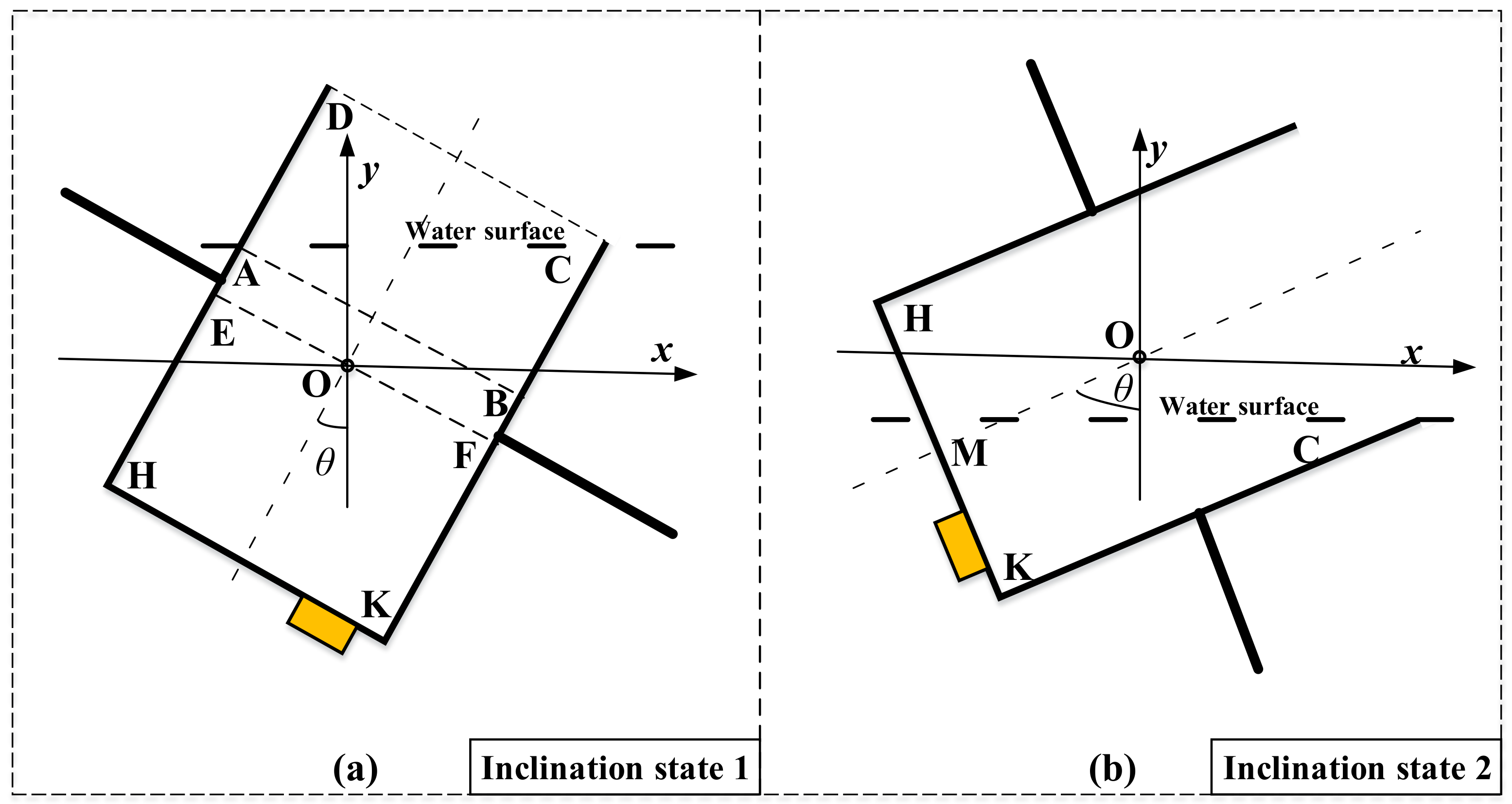
3.1. Working Principle

Figure 2 illustrates the working principle of the investigated structure. The working cycle includes two operational modes for different hydroelectric conditions: an intermittently rotating operation mode and a continuously rotating operation mode. At ultra-low and low flow rates, the investigated structure works in the intermittent rotating operation mode. When the hybrid structure is empty, the hybrid structure is tilted at a small angle. With the increase in water flow injection, the hybrid structure gradually becomes upright. When the structure is full, the hybrid structure pours all the water out through self-tipping. The dynamic change of the state of the hybrid structure between “Full” and “Empty” during the working cycle is similar with the dynamic relationship between “Yin” and “Yang” of TaiJitu [28] as shown in Figure 2. Both the small points in TaiJitu represent the intermediate state between empty (white color) and full (black color). The difference is that the small black point in the TaiJi symbol represents the process of water flow into the hybrid structure, and the small white point in the TaiJi symbol represents the process of water releasing. At medium and high flow rates, the structure works in a continuously rotating operation mode. The hybrid structure continuously rotates under water flow excitation, as shown in Figure 2. Regardless of whether the hybrid structure is intermittent or continuous, the rotational mechanical energy of the hybrid structure can be harvested by electromagnetic induction or piezoelectric effects to supply electrical energy to electronic devices.

3.2. Modelling

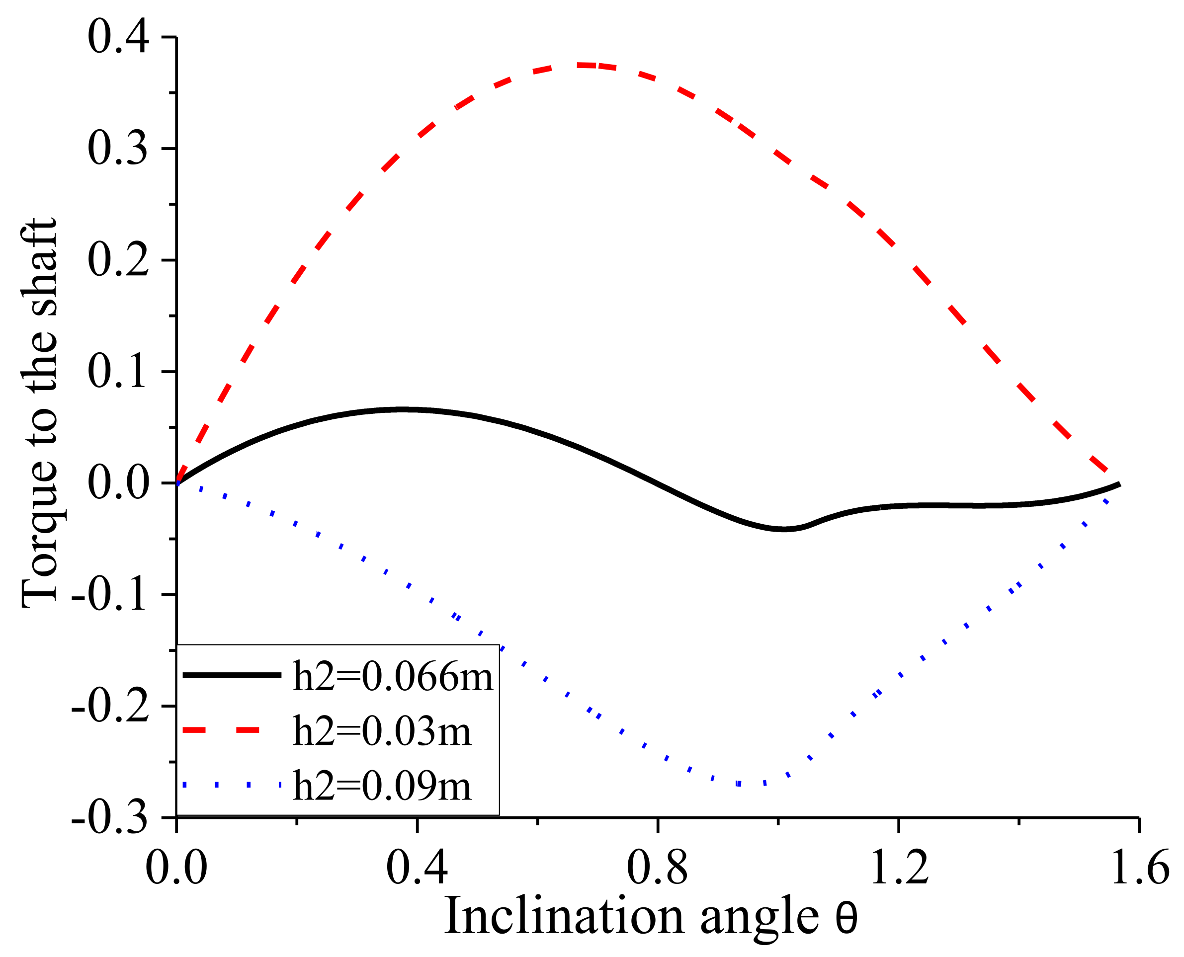
3.2.1. Modelling of the Hybrid Structure

At low flow rates, the investigated structure works in the intermittently rotating operation mode, which mainly follows the working mechanism of the Qiqi structure. The self-tipping feature of the hybrid structure is discussed in this subsection. Water flow into the hybrid structure induces a relative change in position between the overall structural barycenter and the rotating shaft, which causes the hybrid structure to flip itself. The modeling of the torque generated by the water to run the shaft was established during the process of water releasing. Figure 3 shows the half-cut cross section of the hybrid structure in the initial state. The inclination angle is set to θ. According to the position change of the water surface AC inside the hybrid structure, two inclination states 1 and 2 are divided and analyzed. When the water initially flows out of the hybrid structure, the water surface AC only intersects with two sidewalls DH and CK, which represents inclination state 1, as shown in Figure 3a. When there is already a lot of water flowing out of the structure, the water level CM intersects with the bottom HK and one sidewall CK, which represents the other inclination state 2, as shown in Figure 3b.
Assuming the torque by tilting the investigated structure is positive, the torques to shaft O are obtained as MEFKH, MABFE, and MCAB in inclination state 1, respectively. The total torque can be expressed as M1:
M E F K H = 2 ρ g a b h 2 2 sin θ
M A B F E = 2 ρ g a b h 1 h 2 2 b tan θ 2 sin θ
M C A B = 4 ρ g a b 2 tan θ b cos θ + 3 h 1 h 2 sin θ 4 b tan θ sin θ 3
M 1 = M C A B + M A B F E + M E F K H , 0 θ < tan 1 h 1 2 b
The torque MCMK to shaft O in inclination state 2 can also be given as
M 2 = M C M K = 2 ρ g a b h 1 1 sin θ tan 1 h 1 2 b 3 cos tan 1 h 1 2 b sin θ 2 h 1 3 h 2 sin θ + 2 b cos θ cos tan 1 h 1 2 b sin θ + 2 b sin θ tan 1 h 1 2 b b , tan 1 h 1 2 b θ < π 2
Based on the obtained torque of the water to the shaft, the work W done by the water can be obtained as
W = 0 tan 1 h 1 2 b M 1 d θ + tan 1 h 1 2 b π 2 M 2 d θ
By disregarding the frictional force of the shaft, all the water in the hybrid design can stream out when the work W surpasses zero. Notwithstanding, it ought to be noticed that the work W cannot greatly surpass zero. Figure 4 shows the force of the water on the shaft corresponding to the inclination angle. The value of h2 greatly affects the work W, as shown in Figure 4. The value of h2 around 0.6 m makes the work W slightly larger than zero. The value of h2 in the experimental prototype is set to 0.066 m. Thus, the value 0.066 m is correspondingly used for h2 in the theoretical discussion. Under this condition, the hybrid structure doesn’t turn until it is near full. After the water was spilled out, the hybrid structure got back to its initial inclination state. In any case, the hybrid structure pivots consistently at relatively high flow rates due to blade impacts. When h2 is equivalent to 0.03 m (for example under 0.066 m), the work W is greatly bigger than zero. Under this condition, the hybrid design is effectively upset and flipped before it turns out to be full. When h2 is equivalent to 0.09 m (for example greater than 0.066 m), the work W is smaller than zero. Under this condition, the hybrid design can’t be flipped regardless of whether it is full.

3.2.2. Modelling of Energy Harvesting Applications Using the Hybrid Structure

To study the hydroelectric energy harvesting properties using the hybrid structure, the hybrid structure is applied to hydro piezoelectric energy harvesting. To compare the performance between the hybrid design and the Qiqi design, the application of hydro piezoelectric energy harvesting using the hybrid structure, as shown in Figure 5 and Table 2, is set to be similar with the piezoelectric energy harvesting structure using the Qiqi structure [27]. Specifically, the energy harvesting structure using the hybrid structure includes a hybrid structure, a magnetic disk, a piezoelectric cantilever, and a water flow catchment device. The water flow catchment device was used to collect water flowing into the hybrid structure. The magnetic disk and hybrid structure are fixed together. The magnetic disk turns with the rotation of the hybrid structure. The weight of the non-magnetic mass is equal to the weight of the magnetic mass. The magnetic blocks on the disk are mutually exclusive with that on the cantilever beam. A piezoelectric element is bonded to the root of the cantilever beam. Through non-linear magnetic interactions, disk rotation causes damped free beam vibration. Therefore, rotational energy is converted into mechanical energy of the beam. Subsequently, electrical energy through the piezoelectric effect is converted from a part of the elastic mechanical energy. The magnetic disk rotates with the rotation of the hybrid structure, so that the beam is periodically excited by nonlinear magnetic forces. Thus, electrical energy from the piezoelectric element can be harvested by energy-harvesting circuits.
When the disk rotates with the hybrid structure, the magnet on the disk generates a repulsive magnetic force on the cuboidal magnet on the beam. The beam then exhibits damped free damping vibration. According to the literatures [27,29], the magnetic force between the two magnets can be calculated by
F m a g z = ϕ z J J 4 π μ 0 i = 0 1 j = 0 1 k = 0 1 l = 0 1 p = 0 1 q = 0 1 1 i + j + k + l + p + q
ϕ z = Φ 1 + Φ 2 + Φ 3 + Φ 4
Φ 1 = 1 j A g 2 ( 1 ) i a g 2 g z + 1 q C g 2 ( 1 ) p c g 2 I n r 1 j A g 2 + ( 1 ) i a g 2
Φ 2 = g y + 1 l B g 2 ( 1 ) k b g 2 g z + 1 q C g 2 ( 1 ) p c g 2 I n r g y 1 l B g 2 + ( 1 ) k b g 2
Φ 3 = 1 j A g 2 ( 1 ) i a g 2 g y + 1 l B g 2 ( 1 ) k b g 2 tan 1 1 j A g 2 ( 1 ) i a g 2 g y + 1 l B g 2 ( 1 ) k b g 2 g z + 1 q C g 2 ( 1 ) p c g 2 r
Φ 4 = g z + 1 q C g 2 ( 1 ) p c g 2 r
r = 1 j A g 2 ( 1 ) i a g 2 2 + g y + 1 l B g 2 ( 1 ) k b g 2 2 + g z + 1 q C g 2 ( 1 ) p c g 2 2
The specific corner of the magnets determines the values of the parameters i, j, k, l, p, and q. The size (length, width, and height) of the beam magnet are respectively denoted as Ag, Bg, and Cg,. The sizes of the disk magnet are respectively denoted as ag, bg, and cg. All the disk mass blocks have the same size. The distances between the two magnets in the two axes (y, z) are respectively denoted as gy and gz. The rotational angular velocity of the disk is given as ωwl, the distances can be expressed as:
g y = r w l + b sin θ , θ = ω w l t π 2 g z = w ( L b , t ) + r w l + b 1 cos θ + g z 0
The cantilever excited by the rotational magnetic force is described as a single degree-of-freedom vibration model. The dynamic motion equation of the beam according to the Euler–Bernoulli beam hypothesis can be expressed as
M 0 w ¨ t + K 0 w t + C 0 w ˙ t = F m a g z
where the displacement of the cantilever is denoted as w. M0, K0, and C0, denote the equivalent mass, equivalent stiffness, and damping constant of the beam, respectively.
The initial mechanical energy of the disk from the hybrid structure causes the magnetic disk to turn several times within one period. Therefore, the piezoelectric cantilever beam is correspondingly excited several times by the rotational magnetic force in one working period. With the rotation of the disk, the initial kinetic energy gradually decreased and was converted into mechanical energy of the cantilever. Each intermittent rotational excitation generates multiple impulse excitations for the cantilever, followed by the beam damping vibration.
According to the literatures [29,30], the output piezoelectric voltage can be obtained as follows:
V p = 3 E p h p d 31 h p 2 δ L b 2 L b L p 2 4 h p C p E p h p h p 2 3 h p + 3 δ 2 + E b h b h b 2 3 h b δ + 3 δ 2 M e w ¨ , δ = h p 2 E b E p h b 2 2 h p + E b E p h b

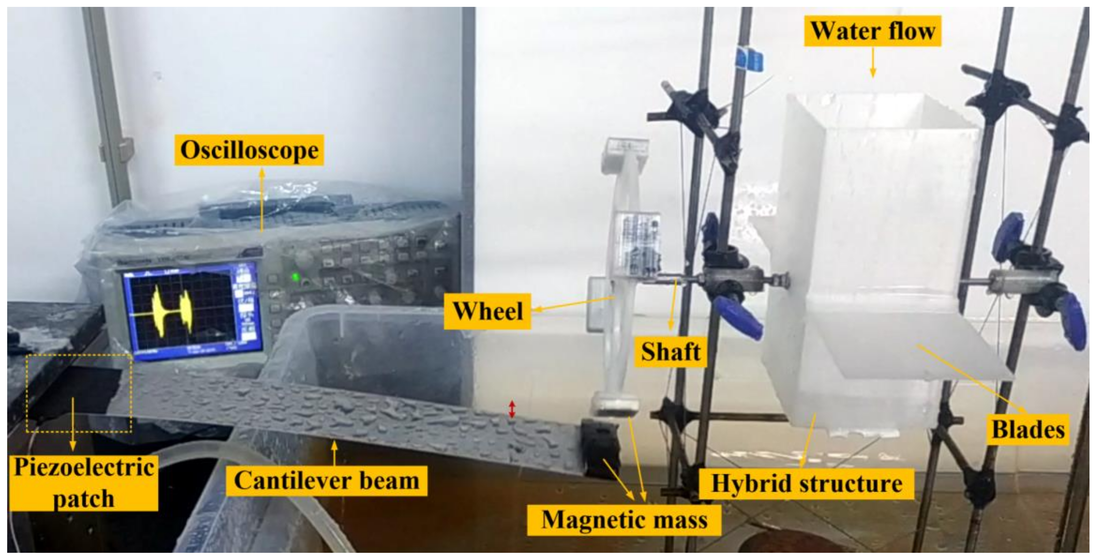
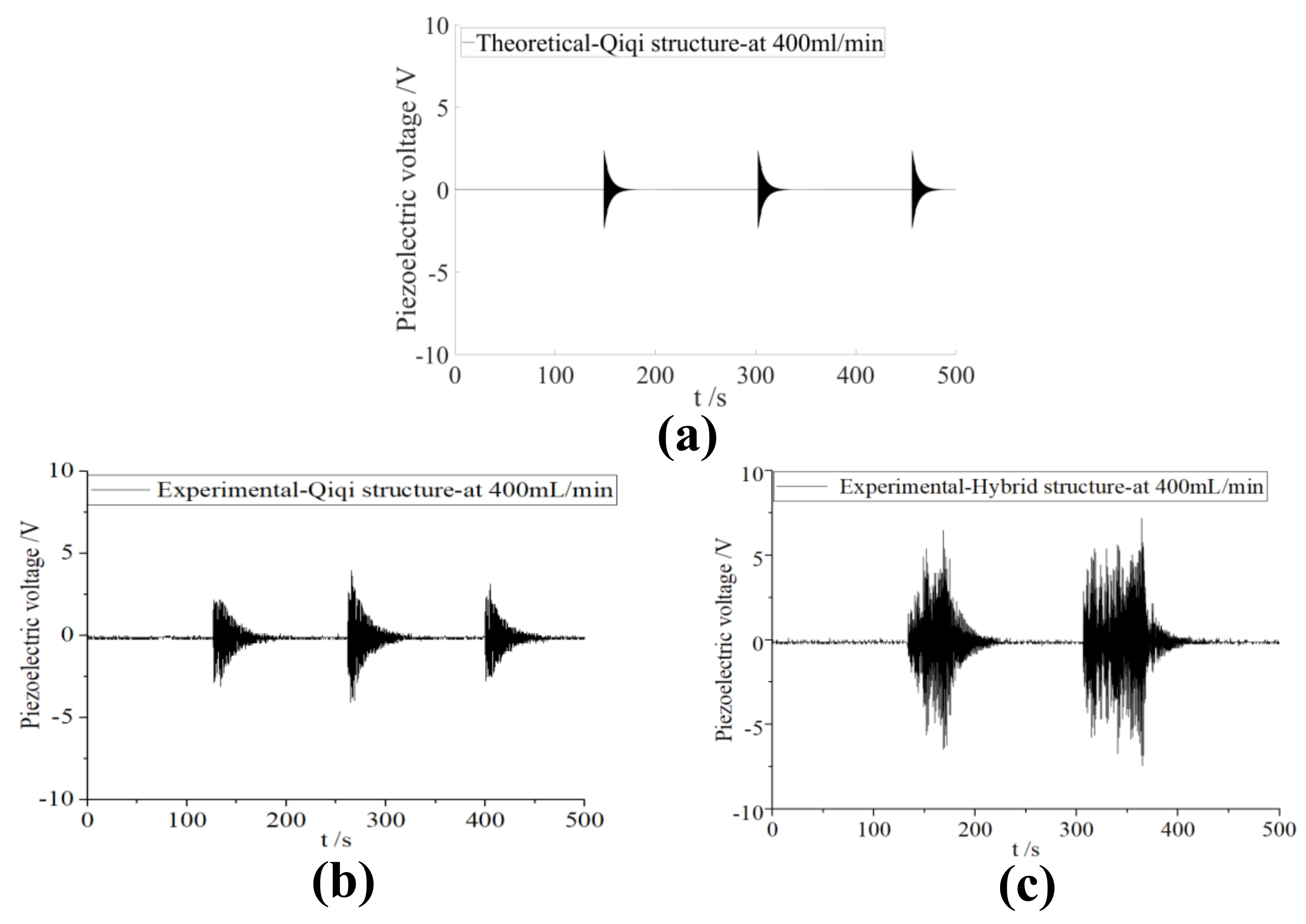
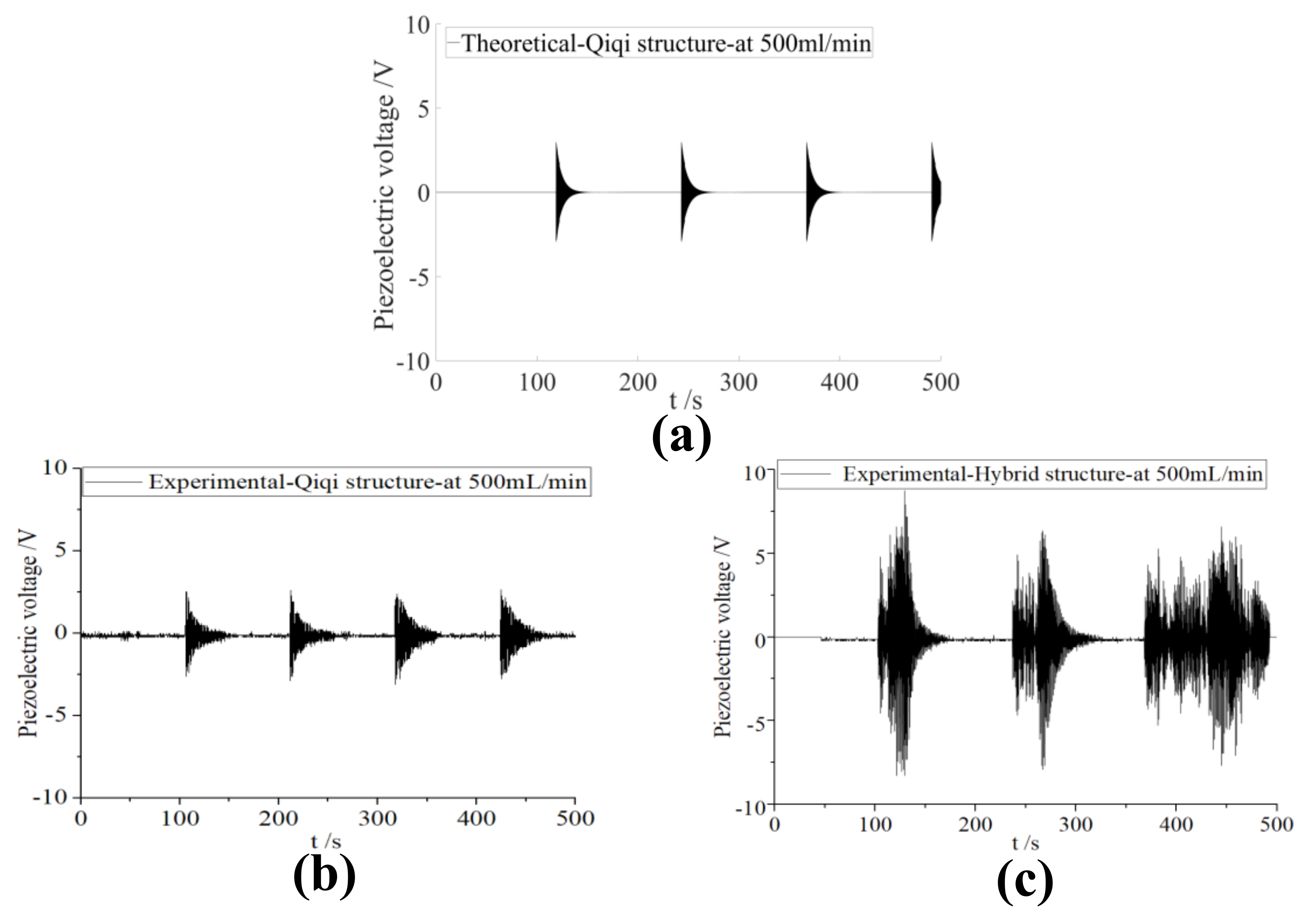
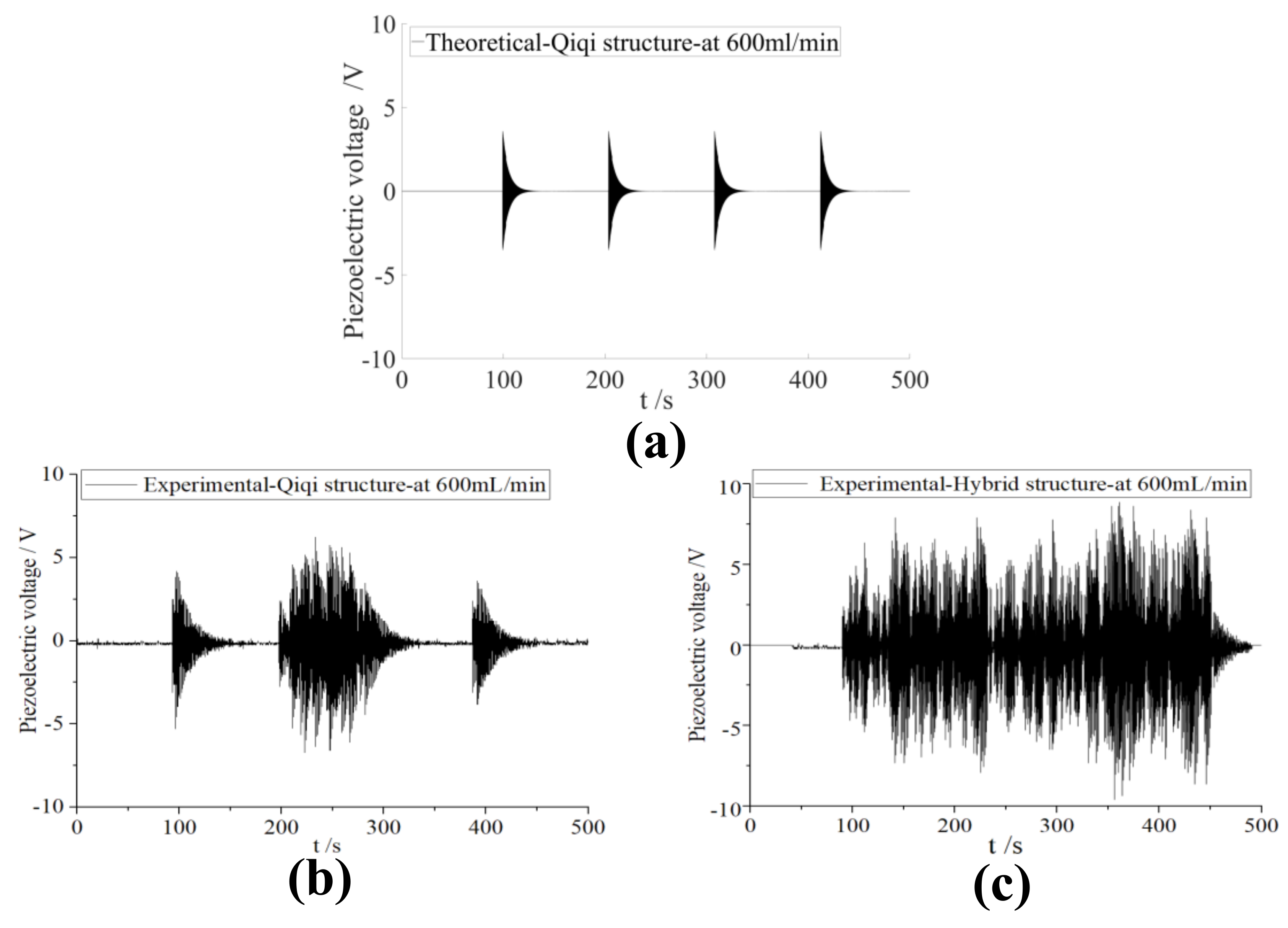
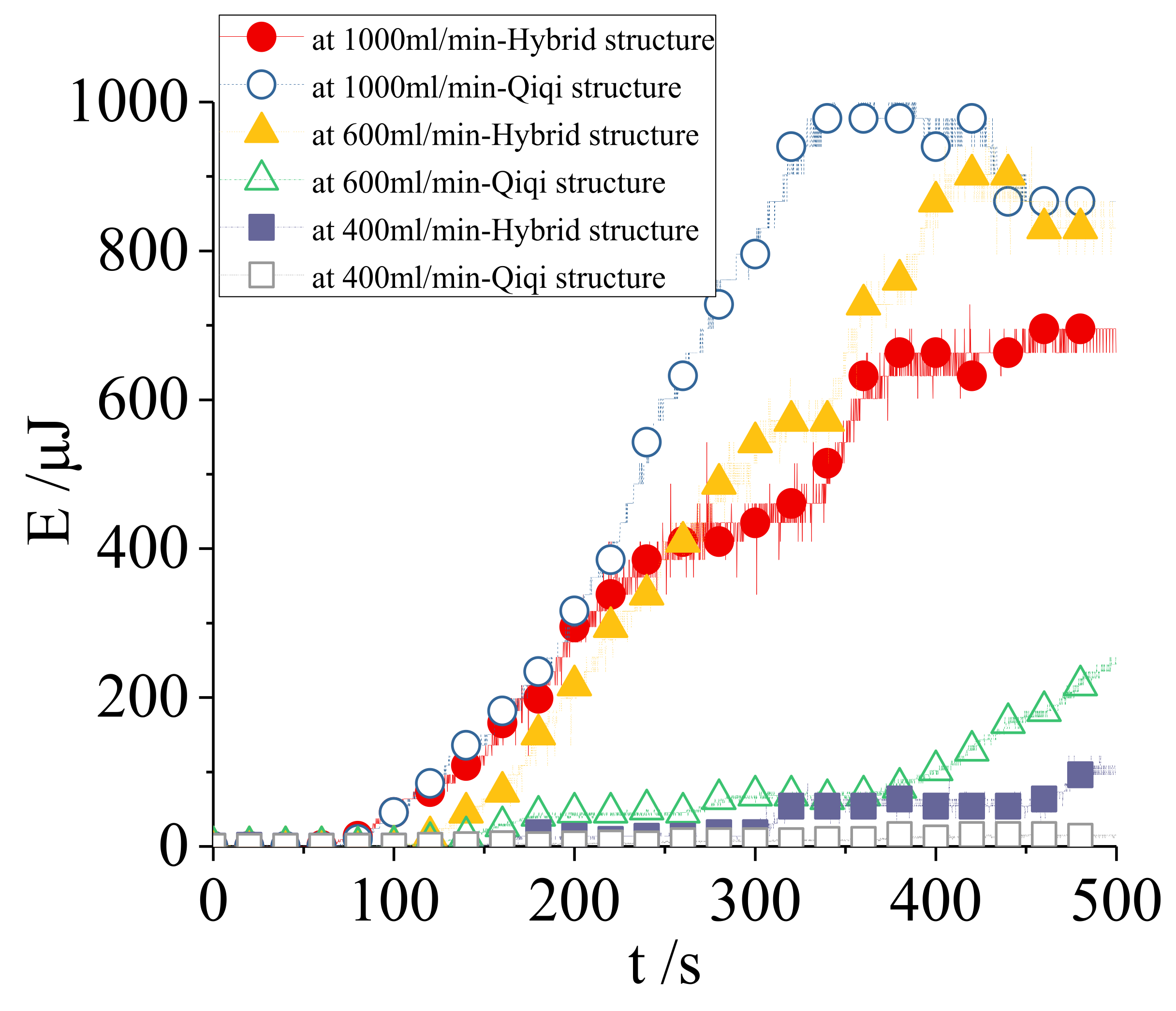
4. Experimental Validation

Figure 6 illustrates the experimental device and an experimental sample of the energy collection application using the hybrid structure, according to Figure 5. The main structural parameters are given in Table 1 and Table 2. The hybrid design and disk were fabricated using 3D printing. The water head was equal to 0.05 m. The results of the Qiqi structure given in the literature [27] are compared with the obtained results of the proposed hybrid structure, as shown in Figure 7, Figure 8, Figure 9 and Figure 10.
Figure 7, Figure 8 and Figure 9 show the output piezoelectric voltages of the hybrid Qiqi structure compared with those of the Qiqi structure under open-circuit conditions at different water flow conditions. The Qiqi structure worked in the intermittently rotating operational mode at 400, 500, and 600 mL/min. Based on the above theoretical modeling, the obtained numerical results agree well with the experimental results at 400 mL/min and 500 mL/min. With an improvement in the water flow, the waiting time in one intermittently rotating working period gradually decreased, and the rotating time increased in the investigated frequency domain. The peak-to-peak output voltage in the Qiqi case also increased. The peak-to-peak output voltage in the Qiqi case increases to approximately 10 V at 600 mL/min. However, there is a discrepancy between the obtained theoretical results of the output piezoelectric voltage and the experimental results at 600 mL/min in the Qiqi case, as shown in Figure 9a,b. This is because the Qiqi structure without blades also captures some of the mechanical energy of the fluid at relatively high flow rates, which makes the rotational mechanism of Qiqi different from theoretical predictions, but such an effect is good for improving energy harvesting. The additional fluid mechanical energy captured by the shape of the Qiqi structure is too hard to be considered in the theoretical modeling. It is also difficult to take blade effect into account in the theoretical modeling of the proposed structure.
To further enhance energy-harvesting performance, blades are introduced in the hybrid structure for increasing the rotation momentum. Figure 7c, Figure 8c and Figure 9c present the experimental voltages of the hybrid Qiqi structure. Compared with those of the Qiqi structure, the peak-to-peak output voltage in the hybrid case achieved a larger value than that of the Qiqi structure. At 400 mL/min and 500 mL/min, the number of working periods was reduced, but the rotating time in each cycle was increased. When the flow rate went up to 600 mL/min, the hybrid structure continued to rotate and exhibited no dwell time once it was rotated. The Qiqi structure cannot work in the continuously rotating operation mode at 600 mL/min until at 650 mL/min [27], which means that the blades can assist the Qiqi structure have a higher rotational speed under ultra-low flow to improve energy harvesting performance. Above 600 mL/min, the hybrid structure rotates continuously. The corresponding experimental videos can be found in Supplementary Materials.
Increasing the water flow rate can help improve the rotational speed of the magnetic disk. Figure 10 presents the experimental voltage of the Qiqi structure and the hybrid Qiqi structure at 800 mL/min and 1000 mL/min. When enhancing the water flow, the global average peak-to-peak value of the experimental voltage of the Qiqi structure increased, as shown in Figure 10c. The global average value of the experimental output piezoelectric voltage of the hybrid structure was decreased, as shown in Figure 10d. To further compare the energy collection performance of the proposed structure with the Qiqi structure. The curves of the charging voltage and the electrical energy under different water flow conditions were obtained, as shown in Figure 11 and Figure 12. The hybrid structure achieved better energy harvesting performance than the Qiqi structure when the flow rate was below 600 mL/min. In particular, the proposed structure charged 902 μJ of electrical energy in the 470 μF capacitor at 600 mL/min, which is six times higher than that using the Qiqi structure. However, the advantage of the hybrid structure gradually weakened with a further increase in the water flow rate > 600 mL/min. The performance of the Qiqi structure was better than that of the hybrid structure at 1000 mL/min. The reason for this is that the blades in the hybrid structure help to further increase the rotational speed of the disk, but there is a discrepancy in the severe phase mismatch between multiple magnetic excitations and motion direction of the vibrating piezoelectric cantilever beam because of the ultra-high rotational speed of the magnetic disk. Therefore, a flow rate of 1000 mL/min is helpful for enhancing the performance of the Qiqi structure but is excessive for the hybrid structure in this hydro piezoelectric energy harvesting application. This is a disadvantage of this piezoelectric energy harvesting application using the hybrid structure, but not a disadvantage of the hybrid structure. The hybrid structure is useful for other hydroelectric applications where high-speed rotational motion helps to improve energy collection performance such as electromagnetic power generation, and it makes up for the low rotation speed of the Qiqi structure at high flow rates.

5. Conclusions

An energy harvester based on a hybrid structure of the Qiqi and turbine structures is proposed to enhance vertical ultra-low water flow energy harvesting performance. The working principle and modeling of the proposed structure were established and demonstrated in detail. Experiments were also done to validate the energy-harvesting performance of the proposed hybrid structure. The results showed that the proposed hybrid structure achieved a superior energy harvesting performance than the previous Qiqi structure without blades [27] < 600 mL/min. In particular, the proposed structure charged 902 μJ of electrical energy in a 470 μF capacitor at 600 mL/min. The obtained electrical energy was six times higher than that obtained using the previous structure. Therefore, the proposed structure has a higher rotational velocity than the previous Qiqi structure without blades under ultra-low flow in order to harvest more low-flow fluid energy. In general, this study provides a new idea for designing rotational turbine structures to improve the energy collecting effect of ultra-low-flow fluid energy and be compatible with medium and high flow. The proposed structure works at wide-range flow rates compared with the turbine structure and the Qiqi structure under vertical low water flow excitation. Furthermore, the hybrid structure is also useful for other hydroelectric applications where high-speed rotational motion helps to improve energy collection performance such as electro-magnetic power generation, and it makes up for the low rotation speed of the Qiqi structure at high flow rates. In practical applications, the proposed structure can be made into large structural parts according to the practical hydraulic conditions for improving energy harvesting performance.

Supplementary Materials

The following are available online at www.mdpi.com/article/10.3390/en14227601/s1, Video S1: experimental videos.

Author Contributions

Conceptualization, B.B.; methodology, B.B.; software, B.B.; validation, B.B.; formal analysis, B.B.; investigation, B.B.; resources, B.B.; data curation, B.B.; writing—original draft preparation, B.B.; writing—review and editing, B.B., Q.W., Y.W. and P.L.; visualization, B.B.; supervision, B.B.; project administration, B.B. and Q.W.; funding acquisition, B.B. and Q.W. All authors have read and agreed to the published version of the manuscript.

Funding

This research is supported by Shenzhen Science and Technology Program (Grant No. KQTD20200820113004005), National Natural Science Foundation of China (Grant No. 52005242) and key scientific research projects of universities in Guangdong province (Grant No: 2018KZDXM064).

Data Availability Statement

The data and experimental video presented in this study are available on request from the corresponding author.

Conflicts of Interest

The authors declare no conflict of interest.

References

  1. Hosseinie, R.; Roohi, R.; Ahmadi, G. Modeling and analysis of a fully passive swinging sail wind turbine. Wind. Energy 2021, 24, 653–671. [Google Scholar] [CrossRef]
  2. Pustina, L.; Lugni, C.; Bernardini, G.; Serafini, J.; Gennaretti, M. Control of power generated by a floating offshore wind turbine perturbed by sea waves. Renew. Sustain. Energy Rev. 2020, 132, 109984. [Google Scholar] [CrossRef]
  3. Fang, S.; Wang, S.; Zhou, S.; Yang, Z.; Liao, W.H. Exploiting the advantages of the centrifugal softening effect in rotational impact energy harvesting. Appl. Phys. Lett. 2020, 116, 063903. [Google Scholar] [CrossRef]
  4. Fang, S.; Wang, S.; Zhou, S.; Yang, Z.; Liao, W.H. Analytical and experimental investigation of the centrifugal softening and stiffening effects in rotational energy harvesting. J. Sound Vib. 2020, 488, 115643. [Google Scholar] [CrossRef]
  5. Ma, P.; Liu, G.; Wang, H.; Wang, Y.; Xie, Y. Co-simulations of a semi-passive oscillating foil turbine using a hydraulic system. Energy 2021, 217, 119323. [Google Scholar] [CrossRef]
  6. Badhurshah, R.; Dudhgaonkar, P.; Jalihal, P.; Samad, A. High efficiency design of an impulse turbine used in oscillating water column to harvest wave energy. Renew. Energy 2018, 121, 344–354. [Google Scholar] [CrossRef]
  7. Bhattarai, S.; Vichare, P.; Dahal, K.; Al Makky, A.; Olabi, A. Novel trends in modelling techniques of Pelton Turbine bucket for increased renewable energy production. Renew. Sustain. Energy Rev. 2019, 112, 87–101. [Google Scholar] [CrossRef]
  8. Breeze, P. Chapter 8-Hydropower. In Power Generation Technologies, 2nd ed.; Breeze, P., Ed.; Newnes: Boston, MA, USA, 2014; pp. 153–179. Available online: https://www.sciencedirect.com/science/article/pii/B9780080983301000089 (accessed on 1 November 2021).
  9. Halder, P.; Doppalapudi, A.T.; Azad, A.K.; Khan, M.M. Efficient Hydroenergy Conversion Technologies, Challenges, and Policy Implication//Advances in Clean Energy Technologies; Academic Press: Cambridge, MA, USA, 2021; pp. 295–318. [Google Scholar]
  10. Hadi, F.; Yang, H.; Traum, M.J. Assessment of Performance of Tesla Turbine in Water Distribution Systems for Energy Harvesting. J. Energy Resour. Technol. 2020, 143, 1–17. [Google Scholar] [CrossRef]
  11. Mohammadi, M.; Maghrebi, M.J. Improvement of wind turbine aerodynamic performance by vanquishing stall with active multi air jet blowing. Energy 2021, 224, 120176. [Google Scholar] [CrossRef]
  12. Fan, X.; Wang, Z.; Wang, Y.; Tan, W. The effect of vortices structures on the flow-induced vibration of three flexible tandem cylinders. Int. J. Mech. Sci. 2021, 192, 106132. [Google Scholar] [CrossRef]
  13. Zamanian, M.; Garibaldi, L. Vortex induced vibration analysis of a cylinder mounted on a flexible rod. Wind Struct. 2019, 29, 441–455. [Google Scholar]
  14. Furquan, M.; Mittal, S. Multiple lock-ins in vortex-induced vibration of a filament. J. Fluid Mech. 2021, 916, 916. [Google Scholar] [CrossRef]
  15. Wang, J.; Sun, S.; Tang, L.; Hu, G.; Liang, J. On the use of meta-surface for Vortex-Induced vibration suppression or energy harvesting. Energy Convers. Manag. 2021, 235, 113991. [Google Scholar] [CrossRef]
  16. Wang, S.; Liao, W.; Zhang, Z.; Liao, Y.; Yan, M.; Kan, J. Development of a novel non-contact piezoelectric wind energy harvester excited by vortex-induced vibration. Energy Convers. Manag. 2021, 235, 113980. [Google Scholar] [CrossRef]
  17. Lai, Z.; Wang, S.; Zhu, L.; Zhang, G.; Wang, J.; Yang, K.; Yurchenko, D. A hybrid piezo-dielectric wind energy harvester for high-performance vortex-induced vibration energy harvesting. Mech. Syst. Signal Process. 2021, 150, 107212. [Google Scholar] [CrossRef]
  18. Yang, K.; Abdelkefi, A.; Li, X.; Mao, Y.; Dai, L.; Wang, J. Stochastic analysis of a galloping-random wind energy harvesting performance on a buoy platform. Energy Convers. Manag. 2021, 238, 114174. [Google Scholar] [CrossRef]
  19. Tosi, L.P.; Dorschner, B.; Colonius, T. Flutter instability in an internal flow energy harvester. J. Fluid Mech. 2021, 915, A40. [Google Scholar] [CrossRef]
  20. Wang, J.; Su, Z.; Li, H.; Ding, L.; Zhu, H.; Gaidai, O. Imposing a wake effect to improve clean marine energy harvesting by flow-induced vibrations. Ocean Eng. 2020, 208, 107455. [Google Scholar] [CrossRef]
  21. Wang, J.; Geng, L.; Ding, L.; Zhu, H.; Yurchenko, D. The state-of-the-art review on energy harvesting from flow-induced vibrations. Appl. Energy 2020, 267, 114902. [Google Scholar] [CrossRef]
  22. Hu, G.; Wang, J.; Tang, L. A comb-like beam based piezoelectric system for galloping energy harvesting. Mech. Syst. Signal Pr. 2021, 150, 107301. [Google Scholar] [CrossRef]
  23. Zaheri Abdehvand, M.; Seyed Roknizadeh, S.A.; Mohammad-Sedighi, H. Parametric study of a novel magneto-electro-aeroelastic energy harvesting system. Proc. Inst. Mech. Eng. Part L J. Mater. Des. Appl. 2021, 235, 2100–2111. [Google Scholar] [CrossRef]
  24. Wang, J.; Geng, L.; Zhang, M.; Zhao, G.; Zhang, M.; Zhang, Z.; Li, Y. Broadening band of wind speed for aeroelastic energy scavenging of a cylinder through buffeting in the wakes of a squared prism. Shock Vib. 2018, 2018, 2039561. [Google Scholar] [CrossRef]
  25. Bao, B.; Wang, Q. A rain energy harvester using a self-release tank. Mech. Syst. Signal Pr. 2021, 147, 107099. [Google Scholar] [CrossRef]
  26. Bao, B.; Wang, Q. Small-scale experimental study on the optimisation of a rooftop rainwater energy harvester using electromagnetic generators in light rains. Int. J. Energy Res. 2020, 44, 10778–10796. [Google Scholar] [CrossRef]
  27. Bao, B.; Wang, Q. Bladeless rotational piezoelectric energy harvester for hydroelectric applications of ultra-low and wide-range flow rates. Energy Convers. Manag. 2021, 227, 113619. [Google Scholar] [CrossRef]
  28. Available online: https://en.wikipedia.org/wiki/Taijitu (accessed on 1 November 2021).
  29. Akoun, G.; Yonnet, J.P. 3D analytical calculation of the forces exerted between two cuboidal magnets. IEEE Trans. Magn. 1984, 20, 1962–1964. [Google Scholar] [CrossRef]
  30. Erturk, A.; Inman, D.J. Piezoelectric Energy Harvesting; John Wiley & Sons: Hoboken, NJ, USA, 2011. [Google Scholar]
Figure 1. (a) 3D view of the investigated hybrid Qiqi structure; (b) 2D view of the hybrid structure.
Energies 14 07601 g001
Figure 2. Working principle of the investigated structure.
Energies 14 07601 g002
Figure 3. Different inclination situations of the hybrid design when it is flipped. (a) inclination state 1; (b) inclination state 2.
Energies 14 07601 g003
Figure 4. Torque of the water to the shaft corresponding to inclination angle (θ).
Energies 14 07601 g004
Figure 5. A hydroelectric energy harvesting application using the hybrid structure.
Energies 14 07601 g005
Figure 6. Experimental set-up of the hydroelectric energy harvesting application using the proposed hybrid structure.
Energies 14 07601 g006
Figure 7. Performance comparison between the Qiqi structure and the proposed hybrid structure: (a) theoretical piezoelectric voltage of the Qiqi structure at 400 mL/min; (b) experimental piezoelectric voltage of the Qiqi structure at 400 mL/min; (c) experimental voltage of the proposed hybrid structure at 400 mL/min.
Energies 14 07601 g007
Figure 8. Performance comparison between the Qiqi structure and the proposed hybrid structure: (a) theoretical voltage of the Qiqi structure at 500 mL/min; (b) experimental voltage of the Qiqi structure at 500 mL/min; (c) experimental voltage of the hybrid structure at 500 mL/min.
Energies 14 07601 g008
Figure 9. Performance comparison between the Qiqi structure and the proposed hybrid structure: (a) theoretical voltage of the Qiqi structure at 600 mL/min; (b) experimental voltage of the Qiqi structure at 600 mL/min; (c) experimental voltage of the hybrid Qiqi structure at 600 mL/min.
Energies 14 07601 g009
Figure 10. (a) Experimental voltage of the Qiqi structure at 800 mL/min; (b) experimental voltage of the hybrid structure at 800 mL/min; (c) experimental voltage of the Qiqi structure at 1000 mL/min; (d) experimental voltage of the hybrid structure at 1000 mL/min.
Energies 14 07601 g010
Figure 11. Charging process under different water flow conditions.
Energies 14 07601 g011
Figure 12. Electrical energy stored under different water flow conditions.
Energies 14 07601 g012
Table 1. Main parameters of the hybrid Qiqi structure.
ParametersAnnotationValue
Lbl × Wbl × hblThe size of the blade0.08 m × 0.075 m × 0.0015 m
2 × athe width of the Qiqi structure0.007 m
2 × bthe length of the Qiqi structure0.009 m
h1The height of the Qiqi structure0.16 m
h2The height of the rotating shaft0.066 m
VvolThe volume of the hybrid Qiqi structure990 mL
Table 2. Main parameters of energy harvesting application using the hybrid structure.
ParametersAnnotationValue
Lb × Wb × hbThe size of the cantilever beam0.36 m × 0.06 m × 0.0015 m
ρbThe beam density7.93 × 103 kg/m3
EbThe beam young modulus19.9 × 1010 N/m2
Lp × Wp × hpThe PZT size0.02 m × 0.06 m × 0.0007 m
σpThe PZT poisson’s ratio0.35
ρbThe PZT density7.6 g/cm3
EpThe PZT young modulus6.2 × 1010 N/m2
d31Piezoelectric charge constant−340 PC/N
ε33T0Relative electrical permittivity5000
mmagThe mass on the beam360 g
J’,JThe magnetization of the magnets1.2 T
μ0Vacuum permeability4π × 10−7 N/A2
rwlThe disk radius0.07 m
ag × bg × cgThe size of the mass on the disk0.02 m × 0.03 m × 0.005 m
Ag × Bg × CgThe size of the mass on the beam0.02 m × 0.06 m × 0.01 m
gGravitational acceleration9.8 N/kg
Publisher’s Note: MDPI stays neutral with regard to jurisdictional claims in published maps and institutional affiliations.

