1. Introduction
Concentrating Solar Power (CSP) is an emerging technology that can play an important role in the future low-carbon energy system. Differently from other non-programmable Renewable Energy Sources (RES) and technologies such as photovoltaic (PV) and wind, CSP enables the “dispatchability” of solar energy thanks to the integration of Thermal Energy Storage (TES) systems, at competitive costs [
1,
2,
3,
4]: the suitable design of the CSP plant with TES can complement other non-programmable technologies to maximize the solar footprint in the power grid [
5].
The above statement highlights the key feature of CSP to guarantee base load and flexibility in power generation. This flexibility is primarily obtained by means of the Thermal Energy Storage system, which allows controlling the power block output (in a wide range) depending on the utility grid requirements. An additional degree of flexibility is provided by using a back-up heat source to supply the heat when the TES system is discharged, as it may happen after periods (days) with low direct normal solar irradiance (DNI, e.g., in the winter). Therefore, combining CSP plants with gas heaters is a common practice to increase the utilization factor of the power plant and, at the same time, introduce an additional degree of flexibility [
6,
7,
8,
9,
10].
New generation CSP plants make use of Molten Salts (MS) as heat storage medium and, in some cases, also as Heat Transfer Fluid (HTF) in the solar collectors [
11,
12]. The molten salt commonly used in CSP plants consists of a binary mixture of sodium and potassium nitrates (NaNO
3/KNO
3, 60/40%w), namely the “solar salt”, with typical operation range from 290 °C up to 565 °C [
11,
12,
13]. Alternative molten salt mixtures have also been proposed, characterized by lower freezing temperatures to facilitate plant operation, such as the ternary mixture where calcium nitrate is added, i.e., the NaNO
3/KNO
3/Ca(NO
3)
2 mixture (15/43/42%w), also called Hitec XL
®, with typical operation range from 200 °C up to 425 °C [
13,
14].
It is noteworthy that, besides power production in CSP systems, the hybridization of concentrating solar systems with a MSH is also useful when process heat is supplied to industrial processes that require steady and stable heat supply. This is the case, for example, of the solar steam reforming [
15,
16,
17] and of the hydrothermal conversion of biomass driven with solar heat [
14,
18].
The hybridization of a concentrating solar plant with back-up fuels can be done at the molten salt level by means of a suitable Molten Salt Heater (MSH) to directly transfer the heat of combustion carried by flue gases to the molten salt flowing in the heat exchanger. Therefore, proper interfaces should be specifically developed considering the specific properties of molten salts—compared to other HTFs, e.g., thermal oils—such as thermal the stability of the molten salt and its physical properties (density, viscosity, thermal conductivity, heat capacity).
This paper presents the results obtained in the experimental validation of an innovative gas-fueled Molten Salt Heater (MSH) prototype (around 90 kW thermal duty to molten salt) installed a molten salt loop, namely the MoSE (Molten Salt Experiences) facility at ENEA-Casaccia research center (Rome, Italy). The aim was to reproduce the real heat exchange conditions between a flue gas on the tube bundle (combustion products and air up to 700 °C) and the molten salt flowing inside the tubes, under a wide operation range. This experimental loop allowed to simulate fluid circulation inside the MSH to optimize its performances, manage specific situations and model the heat transfer process in order to obtain data for the interpretation of full-size MSH systems.
Experimental results have been obtained in the European 7FP projects Hysol (Innovative Configuration for a Fully Renewable Hybrid CSP Plant) and MATS (Multipurpose Applications by Thermodynamic Solar) aiming at integrating the MSH in larger CSP plants. Specifically, the development and validation of the MSH prototype allowed to design a larger scale MSH unit (>2 MW thermal) as back-up for a molten salt parabolic trough solar field in the MATS CSP plant built in Egypt [
12].
In this paper the experimental results obtained with the MSH prototype are presented and analyzed with the validation of heat transfer correlations, using the above mentioned two different molten salt mixtures: the “solar salt” binary mixture and the ternary Hitec XL
® mixture. In the next section,
Section 2 “Materials and methods”, detailed description of the developed MSH mock-up and of the experimental methods are provided.
Section 3 “Experimental results and discussion” reports the results obtained in experimental tests when different parameters have been changed. In
Section 4 “Analysis of results” the values of the heat transfer coefficient obtained with the above mentioned experimental data are compared with those derived from theoretical correlations. Finally, in
Section 5 “Conclusion” relevant results are summarized.
2. Materials and Methods
2.1. Experimental Plant: The MSH Prototype
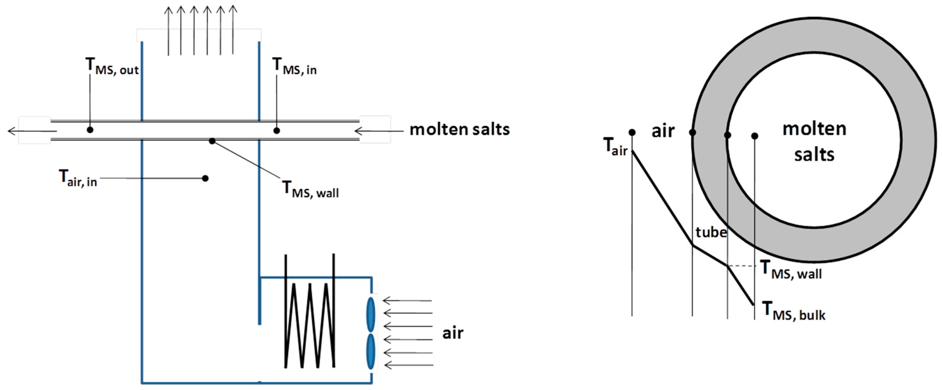
The MSH mock-up was designed according to the conceptual scheme reported in
Figure 1. The idea was to reproduce the “real” heat exchange conditions between molten salts flowing in the tubes and hot flue gases.
The MSH prototype had to be instrumented with thermocouples and flow meters, both on the gas and molten salt sides, in order to obtain performance data.
Figure 2 shows the molten salt experimental loop (MoSE) where the MSH prototype was connected. This experimental loop, initially used to carry out material corrosion tests of steel samples exposed to flowing solar salt (at maximum temperature of 550 °C), was adapted in order to test the air/molten salt heat exchange both with the binary solar salt mixture and the ternary Hitec XL
® mixture. The molten salt wet elements are made of stainless steel type 321; the fluid stored in a tank (ca. 500 L) is pumped at the desired flow rate by means of a vertical centrifugal immersion pump adapted to work with molten salts up to 520 °C; an electrical heater (ca. 60 kW) allowed to obtain the desired inlet temperature in the MSH mock-up (T
MS,in). More details of the MoSE loop are reported in a previous paper [
15].
The design of the MSH mock-up has been carried out taking into account the constraints imposed by key components of the MoSE loop, such as the molten salt pump and the air cooler (
Figure 2) which determined the molten salt flow rate and the thermal duty of the MSH.
Table 1 summarizes the main features of the MSH mock-up system installed in the MoSE facility.
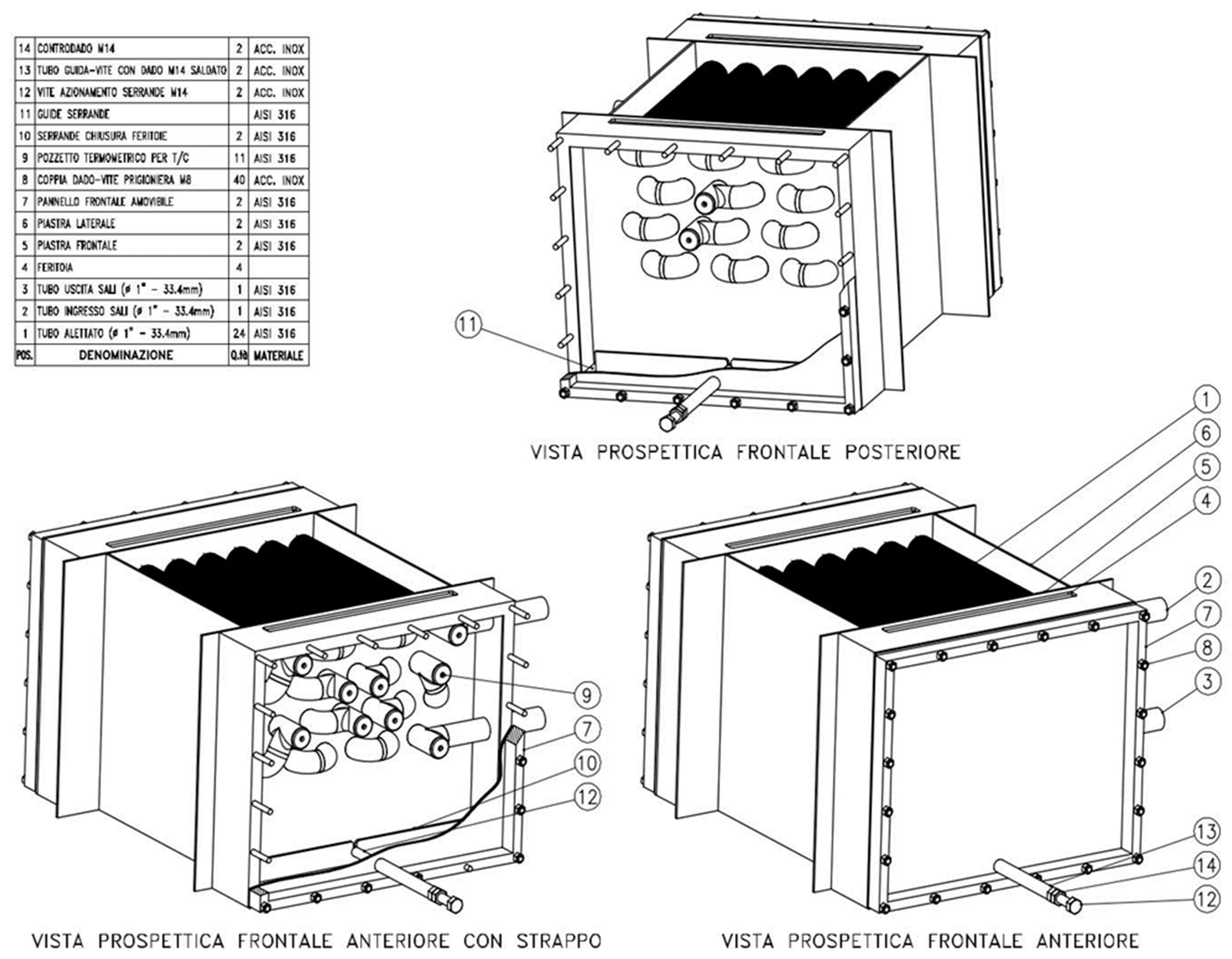
Figure 3 shows a general drawing of the MSH mock-up.
Figure 4 shows a picture of the prototype integrated in the molten salt loop.
2.1.1. Hot Gas Generation System
The blue fan shown in
Figure 4 is the one used for the quenching air, supplied by Stiavelli S.r.l. model (11 kW nominal power). It is controlled by a Danfoss inverter directly connected to the Digital Control System (DCS) of the MoSE plant. The burner was provided by the SAIT S.r.l. company (500 kW nominal power). A 4–20 mA signal coming from the control system can regulate the burner thermal power through the fuel valve; the latter is mechanically connected to the primary air valve in order to keep a fixed mass ratio. Both the primary and secondary air ducts are equipped with a hot wire mass flowmeter whose precision is declared to be within ±1.5% of the maximum measurable value set to 600 kg/h and 2160 kg/h, respectively. Hot wire mass flowmeters are also positioned on the fuel ducts. The precision in this case is expected to be within ±1% of the maximum measurable value set to 43.2 kg/h for LPG and 101 kg/h for the biogas-like stream.
A differential pressure gauge was also installed on the system in order to monitor the pressure in the combustion chamber and pressure drops.
Basically, the experimental system was composed of the following main components:
a circular (horizontal cylinder) combustion chamber ending with a vertical convective zone with rectangular section;
a gas burner for LPG or “biogas” like mixtures (i.e., methane/CO2 mixtures) to be operated at variable nominal thermal power in the range of 180–480 kW thermal;
LPG or biogas feeding pipes including valves and devices prescribed by safety regulations;
two industrial fans capable to feed an overall air mass flow rate up to 0.6 kg/s;
a finned tube heat exchanger (namely, the MSH);
an expansion vessel connected at the molten salt outlet from the MSH (as prescribed by safety regulations);
flue gas collector and discharge with exit point 13 m above the ground level.
The combustion chamber with 640 mm inner diameter was designed to reduce the wall heat losses to <80 kW for the maximum inner temperature of 800 °C at the test section, and to limit the external wall temperature to <60 °C (for safety reasons).
A rectangular duct with external section 680 × 580 mm rises from the bottom of the combustion chamber. The adopted materials and thickness are the same adopted for the combustion chamber. The top of the rectangular duct is approximately 2.8 m over the ground level.
The combustion chamber is equipped with three nozzles for the injection of quenching air (
Figure 4) approximately 900 mm downstream the chamber head section. These quenching air nozzles consist of 1 1/2” pipes made of AISI 316 steel, placed 120deg from each other.
The combustion chamber is equipped with the following instrumentation:
a temperature probe (K-type) in the range of 0–2000 °C to measure the internal wall temperature near the burners;
a pressure gauge positioned 100 mm downstream the quenching air injection nozzles to measure the chamber pressure in the range 1–1.2 atm to be operated at high temperature;
gas temperature probe (K-type) to measure the gas temperature in the range 0–1000 °C positioned in the vertical duct at 100 mm from its inlet section.
As mentioned above, the installed burner can be operated with LPG or a biogas-like mixture. The system is capable to commute from one fuel to the other with few seconds stop.
The system includes the fuel feeding pipes equipped with safety devices and mass flow controllers, with uncertainty within ±1.5%. The mass flow rates to be measured are in the ranges of 0 ÷ 0.012 kg/s for LPG and 0 ÷ 0.028 kg/s for biogas-like CH4/CO2 mixtures. Fuels are stocked in pressure vessels and the feeding pipes include suitable pressure regulators.
Both primary and quenching air are injected by means of industrial fans with the following specifications:
air mass flow rate to be treated in the range 0.2–0.6 kg/s;
prevalence in the range 1.5–13 kPa for all the mass flow rates to be investigated;
fan speed control by means of an inverted with the highest degree of electromagnetic protection in order not to interfere with the experimental probes.
A double fan solution was finally selected: the primary air fan is directly controlled by the burner control logics, while the secondary air fan is controlled to achieve the set point temperature of the exhaust gases at the heat exchanger entrance (T
air,in in
Figure 1). The fans were largely over-sized in order to ensure flexibility and good mixing at the quenching air inlet in the combustion chamber. The fans were also equipped with mass flow controllers with uncertainty within ±3%.
The performance of the secondary air fan was also tested: at full power the fan was able to deliver a mass flow rate Q = 1960 kg/h, which is in the expected range and around 30% higher than the expected maximum secondary air mass flow.
2.1.2. MSH Heat Exchanger
The MSH heat exchanger is positioned on the vertical rectangular duct rising from the combustion chamber (
Figure 3 and
Figure 4).
It is important noticing that selected mock-up dimensions and operating conditions (specifically, flow rates and temperatures) reproduce adimensional parameters like Reynolds (Re) and Prantl (Pr) numbers equivalent to those obtained in large-scale plants.
The tube bundle configuration of the MSH was chosen in order to keep the design as compact as possible and to obtain maximum increase of the molten salt temperature on each tube row.
Figure 5 and
Figure 6 show the drawings of the tube bundle of the MSH, composed of 24 tubes, 4 rows and 6 columns, arranged in staggered configuration and connected in series.
Figure 7 shows the manufactured MSH with the heat exchanger box filled with finned tubes and the external bent tubes.
Figure 5 and
Figure 7 also show the fin density of the finned tubes of the MSH. At the end and at the beginning of each tube, K-type thermocouples (positioned in the dead branch of welded tee-junctions) are installed to monitor the temperature of the molten salt stream in the range of 200–650 °C. In total, 11 thermocouples are placed on the molten salt side.
On the gas side, two K-type thermocouples with measurement range of 0–1000 °C are positioned in the inlet and outlet sections of the tube bundle in order to measure the inlet and outlet temperatures of the hot gas (TMS,in and TMS,out, respectively). The sampling points are at least 5 cm away from the plates.
The height of the bundle in the gas flow direction is approximately 20 cm, with the molten salt inlet placed in upper zone of the MSH (
Figure 7). The heat exchanger is made of AISI 316 steel, including finned tubes and junctions described above and four plates for gas collection and tube support. The overall external dimensions are 588 × 540 mm on the horizontal plane and 400 mm height.
The gas outlet to the atmosphere is positioned 13 m from the ground level.
2.2. Materials
Nitrate salts filled in the HTF loop (MoSE plant) were obtained in 25 kg bags from commercial suppliers, using sodium and potassium nitrates with purity >99% (technical grade) from Haifa Italia BASF, respectively; the Hitec® mixture was obtained by adding a metered amount of NitCal K solar grade supplied by Yara consisting of a mixture of calcium and potassium nitrates plus hydration water (KNO3 5Ca(NO3)2 10H2O) and traces of ammonium Nitrate (<1%) that will be removed after first heating and melting.
As far as the fuel gas is concerned, several tests have been carried out using LPG from a 5 bar cylinder supplied by TotalGaz. In order to evaluate the use of biogas-like mixtures as fuel, the typical gas fuel composition of an anaerobic fermentation biogas was simulated with gas cylinders containing the ultrapure mixture CH4/CO2/H2 = 54/45/1 %vol specifically prepared and supplied AirLiquide.
2.3. Experimental Procedures
Experimental test procedures involved initial start-up of molten salt circulation in the MoSE loop, with the desired molten salt flow rate, while the MSH was initially by-passed (
Figure 2). During this phase, the proper set up of molten salt loop parameters (namely, temperatures and flow rate) were checked and stabilized. Also the electrical tracing of the molten salts lines from the by-pass valve to the MSH were activated and the pipes’ wall heated to a temperature much higher than the typical freezing temperature of the used molten salt mixtures (typically >350 °C).
In the meantime, the gas fuel feeding valves (
Figure 4) were opened and the burner started to work at its minimum firing rate. Also the primary and secondary air fans were started.
Following the start-up of the burner and of the molten salt loop, the set point values of the burner were set up, namely the gas fuel (LPG) rate and the fans speed, in order to control the overall thermal power and the gas temperature at MSH inlet (T
air,in in
Figure 1), respectively.
The start-up procedure was concluded by opening the molten salt inlet and outlet valves to the MSH and slowly closing the by-pass valve (
Figure 2) in order to force the molten salt flow through the MSH mock-up.
After start-up, the final set pint values were introduced in the DCS. Specifically:
the overall thermal power was controlled by tuning the LPG flow rate to the burners, by means of the feeding valves;
the gas temperature at MSH inlet (T
air,in in
Figure 1) was controlled by tuning the secondary air fan speed, by means of the inverter;
the molten salt inlet temperature was controlled by tuning the electrical power to the electric heater of the MoSE loop (
Figure 2);
the molten salt flow rate was controlled by adjusting the molten salts pump speed, by means of the inverter, and reading the obtained flow rate on the molten salts flow meter.
Therefore, it was possible to set four operating parameters, namely inlet temperatures and flow rates of the heating air and molten salts, to obtain corresponding outlet temperatures as performance data of the MSH for analysis.
After introducing a new set of the experimental test parameters (gas fuel flow rate, air flow rate, molten salt inlet temperature, and molten salt flow rate) the system was monitored until stable outlet parameters (outlet stream temperatures and flow rates) were obtained for at least 60 min. Then, the outlet values were recorded for further analysis.
When the biomass-like gas mixtures were used as fuel, the fuel changeover was made by opening the valves of the biomass-like gas cylinders and closing the LPG feed valves.
At the end of the experimental tests, the burners were maintained on with minimum firing, in order to keep the MSH pipes hot during the molten salts draining. The molten salt pump was stopped and the molten salt drained from the MSH heat exchanger and from the external piping to be collected inside the storage tank (
Figure 2). The complete removal of the molten salt for the external loop was checked by means of compressed air directly injected through the vent valves set on the top of the loop, thus ensuring that the pipes were completely drained and, hence, avoiding plugging during later cooling (which would hinder next start-up of the molten salt circulation in the loop).
Finally, the molten salt by-pass valve is opened, the valves to the MSH closed, the burner shut down and the electrical tracing of molten salts lines switched-off.
3. Experimental Results and Discussion
Several preliminary tests were carried out in order to characterize the gas-side temperature distribution, pressure drops and performances. Therefore, the MSH was operated with the burner on but without molten salt circulation in the heat exchange tubes. Results showed that temperature and flow distribution were satisfactory; air heat losses in the MSH section were within acceptable limits (<1 °C) especially after the introduction of a suitable insulation material. Additionally, it was possible to verify that pressure drops were not significant in the defined operation range.
3.1. Results Obtained with the Solar Salt
The experimental matrix with obtained experimental results using the solar salt as HTF is reported in
Table 2.
As shown, the molten salt flow rate and inlet temperature were changed, in the range of 0.46–0.93 kg/s and 349–445 °C, respectively. Therefore, different values of the Reynolds number for the molten salt stream were obtained. The outlet temperatures for the molten salt were experimentally measured in the range of 390–480 °C.
Some tests were carried out changing the flow rate and temperature of the inlet hot air (or flue gas) in the range of 0.36–0.48 kg/s and 596–624 °C, respectively. Therefore, different values of the Reynolds number for the hot air stream were obtained too, and the outlet temperatures for the flue gas experimentally determined in the range of 445–521 °C.
Additional tests have been carried out by fueling the gas combustor the biogas-like mixture, using the typical gas fuel composition of an anaerobic fermentation biogas, corresponding to CH
4/CO
2/H
2 = 54/45/1 vol %. Obtained experimental results using the above biogas-like fuel are reported in
Table 2 (test no.11). Due to the limited capacity of the gas stored in the cylinders, only one test has been carried out. Therefore, this test was useful to check the consistency of results after changeover of gas fuel feed. However, due to the large air flow rate (primary plus secondary) compared to the gas fuel flow rate, the heating gas basically consisted of “hot” air with minor amount of CO
2 and steam (<1%). Therefore, gas fuel changeover cannot significantly affect the properties of the heating fluid, but gas fuel changeover can only impact on the secondary air flow rate to be applied to obtain a given inlet air temperature, due to the different heating value of the primary fuel.
Results reported in
Table 2 show that, at equivalent inlet temperature of the molten salt (349 °C in tests 1–3; 404 °C in tests 5–6; ~445 °C in tests 7–9), the higher the MS flow rate the lower is the outlet MS temperature due to the shorter residence time of the HTF in the MSH. Additionally, there is a clear increase of the transferred thermal power (kW) when the inlet MS temperature was lower, due to the higher mean temperature difference between the hot gas (with inlet temperature in the range of 596–599 °C) and the solar salt: when the inlet temperature of the MS increased from 349 °C to 445 °C, the average temperature difference decreased from 150 °C to 96 °C and the thermal power decreased from 57 kW to 37 kW.
3.2. Results Obtained with the Ternary Na/K/Ca Nitrate Mixture
Additional tests have been carried out using the ternary Hitec XL
® mixture (NaNO
3/KNO
3/Ca(NO
3)
2, 15/43/42%w). This mixture has lower freezing temperature around 125 °C but also lower thermal stability, with maximum operation temperature around 425 °C [
13]. However, the relatively high viscosity of this fluid at lower temperatures recommends its utilization at temperatures ≥ 200 °C. As a matter of fact, as shown in
Figure 8, applying the same speed (rpm) of the molten salt pump of the MoSE loop (
Figure 2) the molten salt flow rate significantly decreased when the fluid temperature in the tank was reduced below 230 °C. For this reason, in order to avoid excessive pumping pressures in the MoSE loop, tests for the validation of heat transfer correlations have been carried out at molten salt inlet temperatures >300 °C.
Table 3 reports the obtained experimental results using LPG as fuel and the Hitec XL
® mixture as HTF.
Similarly to the case of the solar salt, results reported in
Table 3 show that, at equivalent inlet temperature of the molten salt (305 ± 2 °C in tests 1–3; 362 ± 2 °C in tests 4–7), the higher the MS flow rate the lower is the outlet MS temperature due to the shorter residence time of the HTF in the MSH.
Table 3 also shows the increase of the transferred thermal power (kW) by increasing the mean temperature difference between the hot gas (with inlet temperature in the range of 609–632 °C) and the molten salt: when the inlet temperature of the MS increased from ~305 °C to ~362 °C, the average temperature difference decreased from 193 °C to 179 °C and the transferred thermal power decreased from about 69 kW to about 48 kW.
4. Analysis of Results
As mentioned in the previous section, experimental tests have been carried out changing operative parameters such as temperatures and flow rates of inlet molten salt and air. Then, measured outlet temperatures of the two streams (molten salt and flue gas) were used for the performance analysis of the MSH mock-up.
Flow rates, temperatures and physical properties of the two streams flowing in the heat exchanger have been used to evaluate key adimensional numbers to be used in the heat transfer correlations, i.e., Reynolds (Re) and Prandtl (Pr).
For the gas stream, the diameter of the equivalent section has been evaluated, considering the cross flow through finned staggered tube bundles (
Figure 5). As result, for the MSH prototype, the equivalent flow section for the heating gas was evaluated to be 0.0604 m
2. For the flue gas side the specific correlations for banks of finned tubes have been applied, as described in the Handbook of Heat Exchanger Design [
19].
In order to obtain the convective heat transfer coefficient for the molten salt (
hs) the Dittus-Boelter correlation has been applied:
where
Nu is the Nusselt number,
d is the pipe internal diameter,
k is the thermal conductivity of the molten salt,
Re is the Reynolds number and
Pr the Prandtl number.
The overall thermal power transferred to the molten salts (
Qs) has been estimated from applied and measured flow rates and temperature (inlet and outlet) of the molten salts. Therefore, after evaluation of the equivalent heat transfer surface (
A, considering the fins efficiency) it was possible to determine the overall heat transfer coefficient of the heat exchanger
ht:
where Δ
TLM is the Logarithmic Mean Temperature Difference, determined from inlet and outlet temperatures of the two streams, and
F is the “correlation factor” that takes into account the divergence of the actual heat exchanger from the “ideal” counter-current arrangement. As a matter of fact, the mock-up is similar to a cross-flow system on each row, but in the MSH prototype with the 4 rows is more similar to a counter-current heat exchanger. Therefore, it was decided to assume
F ≈ 1.
The estimated overall heat transfer coefficient (
ht) is then used to check consistency of theoretically determined heat transfer coefficients
hs and
hf. Neglecting the conductive resistance of the tube and the tube thickness, the overall heat transfer coefficient (
ht) is linked to the heat transfer coefficients in the two fluid sides (
hs and
hf) by the following relationship:
Therefore, assuming the correctness of the heat transfer coefficient of the heating gas crossing the staggered finned tubes (
hf) [
19], from the overall heat transfer coefficient (
ht) determined experimentally it is possible to determine the experimental value of the heat transfer coefficient in the molten salts side (
hs).
4.1. Analysis of Results Obtained with the Solar Salt Mixture
Table 4 reports the heat transfer coefficients
hs,
hf and
ht, obtained by applying the methodology described in the previous section, compared with the corresponding
ht experimental values, when the solar salt HTF was used.
Results reported in
Table 4 clearly show that the limiting resistance to heat transfer in the mock-up is on the external flue gas side (
hs/
hf >> 10). Clearly, the overall heat transfer is determined by the heat transfer on the gas side (
hf): increasing the Reynolds number of the inlet gas stream from about 5100 to about 7000, the overall heat transfer coefficient (
ht) increases from about 41 W/m
2/°C to about 49 W/m
2/°C; differently, fluid-dynamic conditions inside the molten salt side have minor effect.
Figure 9 shows the comparison between the
ht values determined experimentally and the theoretical ones obtained applying the above mentioned correlations. The difference between theoretical and experimental values is usually <± 3% (only in test no. 7 the difference is about 6%) showing the consistency of experimental data with the heat transfer correlations.
Pressure drops of the hot gas have been estimated too, using the correlation provided by Gianolio and Cuti [
20]. Resulting pressure drops are, in all tests, lower than 120 Pa.
4.2. Analysis of Results Obtained with the Ternary Na/K/Ca Nitrate Mixture
Table 5 reports the heat transfer coefficients
hs,
hf and
ht, obtained with the same methodology described in the previous sections, compared with the corresponding
ht experimental values, when the Hitec XL
® mixture was used as HTF.
Again, results reported in
Table 5 clearly show that the limiting resistance to heat transfer in the mock-up is on the external flue gas side (
hs/
hf >> 10). Differently from the previous solar salt case, tests with the Hitec
® mixture have been carried out with similar Reynolds numbers of the inlet gas stream around 5050 (±200). Therefore, from the values reported in
Table 5 it is possible to observe the effect of the fluid-dynamic conditions of the molten salt stream: increasing the Reynolds number of the inlet molten salt from about 5500 to about 13,700, the overall heat transfer coefficient (
ht) increases from about 37 W/m
2/°C to about 40 W/m
2/°C.
Figure 10 shows the comparison between experimental
ht and the theoretical correlations. Once more, the heat transfer correlations allow to satisfactorily predict the heat transfer coefficient in the MSH: according to
Table 5 the maximum error of the theoretical heat transfer coefficient
ht is overestimate by 2–9%.
5. Conclusions
An innovative Molten Salt Heater (MSH) prototype (about 90 kW thermal) has been designed, constructed and integrated in a molten salt loop for its experimental validation and characterization. The developed MSH is representative of a full-scale gas/molten salt heat exchanger to be applied for the hybridization of CSP plants, with the molten salt flowing inside finned tubes cross-flowed with the hot flue gas generated in an upstream combustion chamber. LPG or a biogas-like mixture has been used as gas fuels.
Experimental results obtained with two different molten salt mixtures, the “solar salt” binary mixture and the ternary Hitec XL® mixture, successfully proved the MSH design and allowed validation of heat transfer correlations. Tests have been carried out changing key operative parameters such as molten salt flow rate (0.45–0.94 kg/s) and inlet temperature (303–445 °C), as well the hot gas flow rate (0.34–0.48 kg/s) and inlet temperature (596–632 °C). For both molten salt mixtures, it was demonstrated that heat transfer correlations based on the Dittus-Boelter equation allow to predict experimental results with <10% deviation between experimental and theoretical values of the heat transfer coefficient.
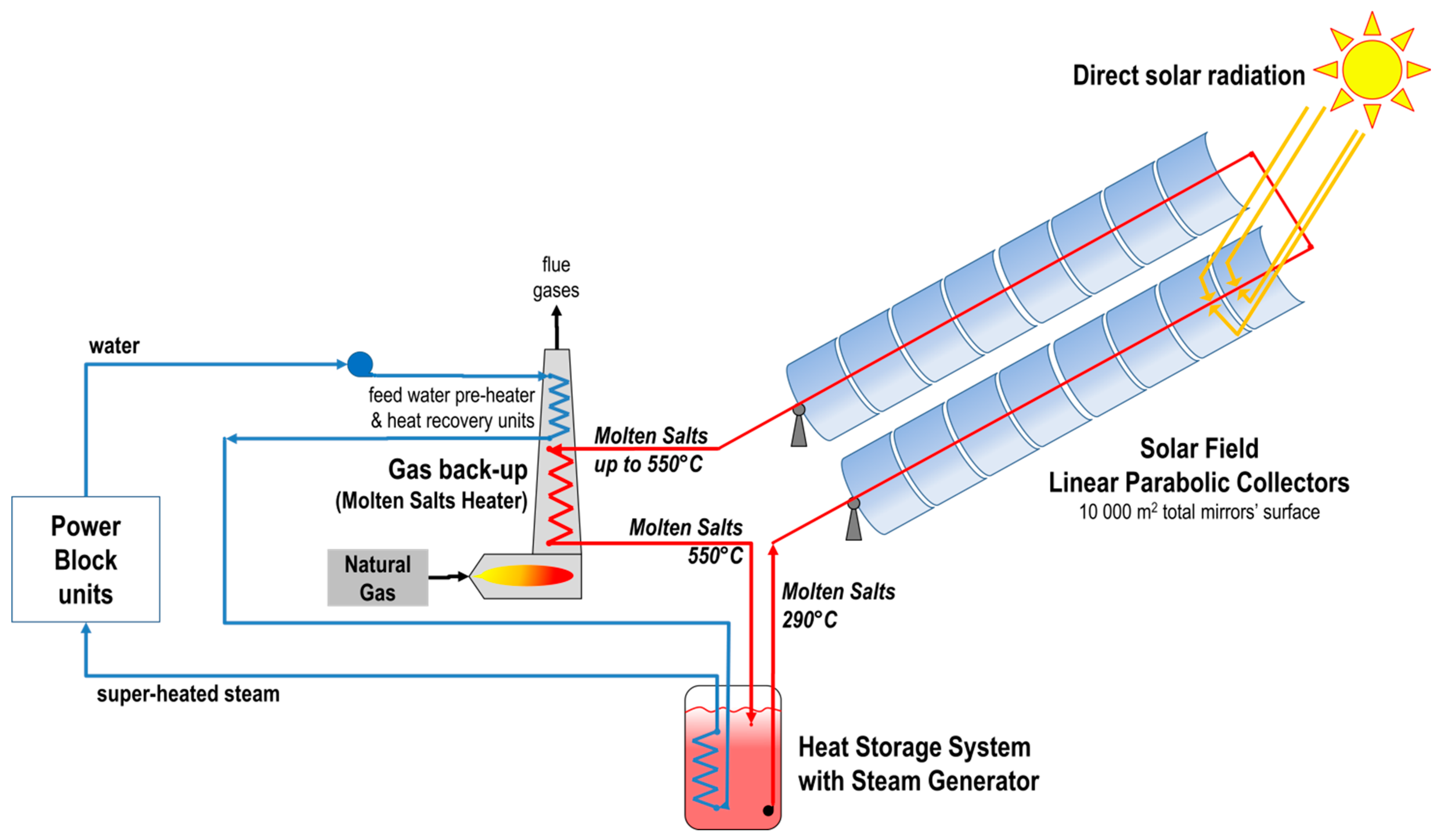
The above results allow the design of larger molten salt heaters for CSP plants using molten salts as heat transfer fluid and where the interface with hot combustion gases is made at the molten salt level (instead of using thermal oil heaters). So far, there are no similar studies published in the open literature where this key interface is validated at prototype level and thermo-fluid dynamics thoroughly investigated. This study provides first input to the design of a larger scale demo unit (>2 MW thermal) as back-up for a molten salt parabolic trough solar field in the MATS CSP plant built in Egypt, in the framework of the project MATS [
12], to demonstrate a hybrid technology on representative environment where the MSH is integrated in a CSP plant architecture:
Figure 11 shows the general layout of MATS plant, where the MSH is connected in series with the solar field in order to adjust the exit temperature of the solar salt and approach the design value of 550 °C; alternatively, the MSH can be connected in a HTF line parallel to the solar filed.


