Article

Wake Expansion and the Finite Blade Functions for Horizontal-Axis Wind Turbines

Department of Mechanical and Manufacturing Engineering, University of Calgary, Calgary, AB T2N 1N4, Canada
Energies 2021, 14(22), 7653; https://doi.org/10.3390/en14227653
Submission received: 19 October 2021 / Revised: 29 October 2021 / Accepted: 8 November 2021 / Published: 16 November 2021
(This article belongs to the Special Issue Wind Turbine Advances)

Abstract

:
This paper considers the effect of wake expansion on the finite blade functions in blade element/momentum theory for horizontal-axis wind turbines. For any velocity component, the function is the ratio of the streamtube average to that at the blade elements. In most cases, the functions are set by the trailing vorticity only and Prandtl’s tip loss factor can be a reasonable approximation to the axial and circumferential functions at sufficiently high tip speed ratio. Nevertheless, important cases like coned or swept rotors or shrouded turbines involve more complex blade functions than provided by the tip loss factor or its recent modifications. Even in the presence of significant wake expansion, the functions derived from the exact solution for the flow due to constant pitch and radius helical vortices provide accurate estimates for the axial and circumferential blade functions. Modifying the vortex pitch in response to the expansion improves the accuracy of the latter. The modified functions are more accurate than the tip loss factor for the test cases at high tip speed ratio that are studied here. The radial velocity is important for expanding flow as it has the magnitude of the induced axial velocity near the edge of the rotor. It is shown that the resulting angle of the flow to the axial direction is small even with significant expansion, as long is the tip speed ratio is high. This means that blade element theory does not have account for the effective blade sweep due to the radial velocity. Further, the circumferential variation of the radial velocity is lower than of the other components.

1. Introduction

Blade element/momentum theory (BEMT) for horizontal-axis wind turbines is so basic that it is covered in every textbook on wind turbine aerodynamics, e.g., Hansen [1] and Schmitz [2]. BEMT balances the changes in axial and angular momentum in the wind flow through the rotor against the lift and drag acting on the blades. The blades are divided computationally into elements that intersect expanding annular streamtubes of the flow. Their axial and angular momentum depend on the average axial (u) and azimuthal (w) velocities of each streamtube whereas the lift and drag depend on the velocities at the blade, u b and w b . In addition, the radial velocity (v) associated with flow expansion, is of the same magnitude as u and thus needs to be considered in determining the accuracy of BEMT, Limacher and Wood [3].
Throughout this paper, a subscript “b” indicates a velocity at the blades and an unsubscripted velocity without an argument is a streamtube average. In addition, all velocities are normalized by the wind speed, so that u is equivalent to the axial induction factor, usually given the symbol a. To maintain a consistent nomenclature for the three velocity components, a will not be used herein. It is reasonable to assume that u u b and w w b as the number of blades, N at any tip speed ratio, λ , or as λ at any N. Most actual wind turbines, however, have N = 2 or 3 and operate around λ 7 , and so there can be significant differences between the velocities at the blades and the streamtube averages. If the blades are equispaced, straight, and lie in the radial direction, these differences are due entirely to the trailing vorticity. In general, the simplest way to account for the differences is through “finite blade functions”, FBFs collectively, or F u = u / u b , F v = v / v b , and F w = w / w b individually.
The three main ways to determine the FBFs are:
(1)
The vast majority of wind turbine codes use Prandtl’s tip loss factor F P which assumes F P = F u = F w . The modern form of F P was developed by Glauert [4] and its implementation is described by Hansen [1] and Schmitz [2]. The formula for F P is computationally cheap and this overrides its limitations of being derived from modelling the trailing vorticity as two-dimensional sheets of vorticity. Modifications to Prandtl’s formulation have been developed by a number of authors, including Shen et al. [5]. A more recent example of this type of analysis is by [6]. None of these modificatons address the effects of wake expansion.
(2)
It is common in propeller analysis, e.g., Epps [7], to use analytical approximations to the complicated Kawada-Hardin (KH) equations for the velocities due to helical vortices of constant pitch and radius. Wood et al. [8] showed that F P approached F u and F w derived from the KH equations, as λ increased. Significant differences, however, occurred for λ 7 . Wood et al. [9] give a brief history of these methods and compare three approximations to the KH equations for a range of vortex pitch applicable to wind turbines and propellers. They showed the best of the approximations (which is used here) is accurate and easy to incorporate in a BEMT code.
(3)
Wimshurst and Willden [10] and Schmitz and Maniaci [11] solved free-wake models to calculate F u and F w . The former were the first to show a difference between F u and F w . This work was followed by Wimshurst and Willden [12] and Wimshurst and Willden [13] using further detailed computational fluid dynamics analysis of the flow over the blades. Free-wake models account for wake expansion which is significant for turbines near maximum power, but are computationally demanding in comparison to BEMT.
A further consideration is that F P or its modifications should not be used when the blade bound vorticity influences the FBFs. Wood et al. [9] give a number of examples where this occurs, including rotors with swept or coned blades. Method 1 and its variations are also inaccurate for a shrouded wind turbine where F u and F w do not go to zero at the blade tips whereas F P does, Vaz et al. [14]. The last two references show that Method 2, either alone or by including the effects of the bound vorticity, can be used for those cases where F P is contraindicated. Method 2, therefore, has the potential to be significantly more general and accurate than Method 1 and much less computationally demanding than Method 3. Its main limitation would appear to be the restriction to trailing vortices of constant pitch and radius, that is, to non-expanding flow. This limitation is due to the lack of analytic solutions for the velocity fields of expanding helical vortices. The purpose of this paper is to investigate the accuracy of Method 2 in the presence of significant flow expansion by using a semi-analytic treatment of the expanding vortices. To the author’s knowledge, this has not been attempted before.
There are several reasons to expect that flow expansion has differing effects on the FBFs. The main reason to anticipate small effects is that F u and F w differ from unity largely because of the 2 π / N azimuthal periodicity of any wake, whether it expands or not. This periodicity strictly applies only in the ideal case of equispaced and aerodynamically equal blades, but is normally assumed in BEMT codes and is implicit in F P . It forces wake uniformity as N . The expectation of large effects of expansion arise from its association with a significant v at the rotor. Limacher and Wood [3] showed that the flow immediately upwind of the rotor is constrained by the “expansion integral”:
0 0 2 π v 2 ( r , θ ) u 2 ( r , θ ) + w 2 ( r , θ ) r d r d θ 0
where the radial (r) integration is from the axis of rotation, r = 0 . θ is the circumferential angle. w = 0 anywhere upwind of the blades, so the integral is dominated by the first and second terms. The integral is strictly zero only in the limit N but is likely to be approximately zero for all N. It is usually assumed that u and v are continuous through the rotor so Equation (1) without the w term holds immediately behind the rotor as well. As shown by van Kuik [15] and Wood and Limacher [16], this is associated with v u at the edge of the rotor, at least for large N. The radial velocity is almost universally ignored in BEMT and there has not been any consistent assessment of its magnitude or importance. This analysis considers v and F v , the latter for the first time. There is also a good reason to expect that expansion effects F u and F w in different ways. Within a helical vortex of constant pitch and radius, u is proportional to the inverse of the pitch p, and Wood and Limacher [16] show that expansion significantly changes the constant of proportionality. On the other hand, expansion has no effect on w as the circulation around a circular contour is zero if the contour is within the helix and proportional to w r if outside, whatever the vortex geometry. Expansion clearly has different effects on u and w and this may well carry over to F u and F w .
Wood and Limacher [16] explored the effects of wake expansion by means of a “Joukowsky” wake which should be applicable at high λ . A single hub vortex lies along the axis of rotation and there are N helical tip vortices. To generalize the KH analysis, ref. [16] assumed the vortex pitch remained constant for the expanding tip vortices, on the grounds that the changing vortex radius was more important than changing the pitch. This allowed a semi-analytic determination of the induced velocities via the Biot-Savart law, as explained in detail in the next Section. They found that wake expansion alters the relationship between u and its far-wake value and that the area of the far-wake was 1.597 times that of the rotor for maximum power output. This is a 20% reduction from the Betz-Joukowsky value of 2, but is still a significant expansion. The present paper extends the Biot-Savart analysis of [16] to compute the three FBFs due to the trailing vorticity in an expanding flow. A direct comparison is then made of F u and F w to F p at high λ where they should have the smallest difference. This point is critical: the comparison of F u and F w to F P is confined in this analysis to conditions where F P should have its highest accuracy.
The Section 2 describes the three main ways of computing the FBFs and details the test cases, for which p was specified as p = 0.1 , 0.05 which resulted in λ = 7.13 , 14.28 , studied by Wood and Limacher [16]. Section 3 has two parts. The first presents the basic comparison of the FBFs and a method is developed to improve the accuracy of F w for expanding wakes. The second subsection concentrates on v and F v and their relations to the expansion integral. Section 3 contains the discussion and Section 4 the conclusions.

2. The Equations for the Induced Velocities and Finite Blade Functions

For completeness, Section 2.1 describes the evaluation of Prandtl’s tip loss factor even though it is well-known. Section 2.2 covers the KH equations and the single formula for F u and F w . Okulov’s approximations to the KH equations are introduced in Section 2.3, and the Biot-Savart calculations are summarized in Section 2.4.

2.1. Prandtl’s Tip Loss Factor

Most BEMT codes assume F u = F w = F P where
F P = 2 π cos 1 exp N ( 1 r ) 2 r sin ϕ .
This equation is derived in Section 4.4 of Glauert [4] by assuming the wake comprises two-dimensional vortex sheets without expansion. The sheets are a constant distance apart which is a similar assumption to that of constant pitch in Wood and Limacher [16]. The use of Equation (2) in blade element-momentum theory is described in most textbooks on wind turbine aerodynamics, e.g., Hansen [1] and Schmitz [2]. The “inflow angle”, ϕ , is the angle between the circumferential velocity and total velocity at the blades. For the present comparisons, we take sin ϕ = p / p 2 + r 2 . In practice, F P is often combined with a similar “hub loss factor”, but this is not appropriate for a Joukowsky wake, as the hub vortex is circumferentially uniform. It is the only straight trailing vortex and thus does not contribute to the difference between w and w b , or to u or u b .
Γ does not appear directly in Equation (2) or any of the other FBF equations for a Joukowsky wake detailed below. In many BEMT simulations, the bound vorticity changes along the blade, so the strength of the vortex shed at the junctions of the blade elements is the difference in the Γ of the elements forming the junction. Since each vortex can contribute to the difference between u and u b , say, the final form of the FBFs depends on the bound vorticity distribution. There is a corresponding dependence on any radial variation in p.

2.2. The Kawada-Hardin Equations

A semi-infinite single ( N = 1 ) helical vortex of constant radius t and pitch p, defined by d x / d θ = p for any point on the vortex, begins at ( 0 , t , 0 ) in cylindrical polar co-ordinates. u at any point ( 0 , r , θ ) in the rotor plane, is given by the KH equations as
u ( 0 , r , θ ) = Γ 4 π p Γ t 2 π p 2 S 1 = u Γ t 2 π p 2 S 1
where
S 1 = m = 1 m K m ( m t / p ) I m ( m r / p ) cos ( m θ ) .
Γ is the vortex strength, and I m ( . ) and K m ( . ) are modified Bessel functions in standard notation. m denotes the order and the prime a derivative with respect to the argument. Helical symmetry requires p u = w r and so the calculation of w, say, is straightforward once u has been found. There is a similar series solution for the flow external to the helix but this is not needed for the present investigation. Kawada [17] and Hardin [18] derived these equations from the velocity potential due to a helical vortex. This methodology has interesting advantages and disadvantages compared to the more common use—an example of which is shown below—of the Biot-Savart law to find the velocities associated with a line vortex of known geometry.
When summed to determine S 1 at the blades, denoted by S 1 , b , the result is Equation (13) of [19]:
S 1 , b = N m = 1 m N K m N ( m N t / p ) I m N ( m N r / p )
as a consequence of the previously mentioned 2 π / N periodicity of the wake when the blades are equispaced and identical. This simplification, called “Kawada cancellation” by Fukumuto et al. [20], removes all terms in the series that are not multiples of N. Thus the flow becomes circumferentially uniform as N increases. Cancellation removes the majority of terms in the series even for N = 3 , say, but this is of little help in accurately determining S 1 , b . Okulov and Sørensen [21] show that the upper limit on m to sum the series to a specified accuracy, m ^ , increases without bound as the vortex is approached, i.e., r t . Wood et al. [9] derive formulae for m ^ that show the unboundedness.
From Equations (3) and (5), F u for a Joukowsky wake containing constant pitch and radius helical vortices, is given by
F u = 1 / 1 2 S 1 , b ( p ) / ( N p ) .
and, like Equation (2) for F P , is not a function of Γ . F u 1 everywhere along a blade because S 1 , b is always negative. Equation (3) has no contribution from the hub vortex which does not influence u and whose induced w must be circumferentially uniform. F w differs from unity because of the spatial variations caused by the tip vortex. These variations also depend on S 1 by the KH equations, with the consequence that F u = F w for the Joukowsky wake with constant radius and pitch. This result was used to check the Biot-Savart formulation described below. It was also checked that the tip vortex gave no contribution to w.
The KH equations were not used in this work to determine S 1 , b . Instead it was found from the approximate equations described in the next Section and F u and F w were computed from Equation (6).

2.3. Okulov’s Approximate Equation for S 1 , b

As described by Wood et al. [9] and in the Appendix to Okulov and Sørensen [21], Okulov [22] derived an approximate equation for S 1 , b :
S 1 , b N 2 K N ( N t / p ) I N ( N r / p ) + A B U + log 1 U N U 2 1 U
where
A = p 2 t 1 + ( t / p ) 2 1 + ( r / p ) 2 1 / 4 , B = 1 24 9 ( t / p ) 2 + 2 c t 3 + 3 ( r / p ) 2 2 c r 3 , and U = r ( c t + 1 ) t ( c r + 1 ) exp 1 + ( r / p ) 2 1 + ( t / p ) 2 N .
The first term in Equation (7) is clearly the first term in the KH Equation (5). Wood et al. [9] tested three approximate equations for S 1 , b and found that (7) was the most accurate over a wide range of p. The evaluation of Equation (7) takes more time than Equation (2) but not substantially more. F u and F w are then found by substitution in Equation (20).

2.4. Using the Biot-Savart Law

Wood and Limacher [16] analyzed a constant pitch, Joukowsky wake with an expanding tip vortex. They used the Biot-Savart law to find the three induced velocities at any point in the rotor plane as
u ( r , θ ) , v ( r , θ ) , w ( r , θ ) = Γ 4 π I u , I v , I w = Γ 4 π 0 i u ( r , θ ) , i v ( r , θ ) , i w ( r , θ ) d 3 d β
where Γ is the vortex strength and the dependence of I u , I v , and I w on r and θ has been suppressed. The integrands are
i u ( r , θ ) = t 2 r t cos ( β θ ) r d t d β sin ( β θ ) , i v ( r , θ ) = p t β cos ( β θ ) + t β d t d β sin ( β θ ) , and i w ( r , θ ) = p r + β d t d β t cos ( β θ ) t β sin ( β θ ) ,
where
d 2 = r 2 + t 2 2 r t cos ( β θ ) + p 2 β 2 .
To evaluate these integrals, the vortex radius t must be known as a function of vortex angle β . WL used the simple form
t = R ( R 1 ) exp ( k β )
where R is the radius of the far-wake. It and the parameter k were set by satisfying the expansion integral, Equation (1), in the form
0 v 2 u 2 r d r = 0 ,
and then requiring the slopes of the vortex surface and streamsurface to be equal at the blade tip. Table 1, taken from Wood and Limacher [16], provides the resulting geometry and power coefficient, C P , of the Joukowsky wake for p = 0.05 , 0.10 which will be used as test cases to assess the effects of expansion in the next Section. As described by [16], these values were found using a pattern search for each p.
In determining the integrands for u and v by integrating over 0 θ 2 π , the sin ( β θ ) terms vanish as they are odd in θ . Wood and Limacher [16] obtained
i v ( x ) = p β π x p 2 β 2 + ( x + t ) 2 1 + m 2 E ( m p ) K ( m p ) , and
i u ( x ) = 1 π p 2 β 2 + ( x + t ) 2 1 + m 2 m t 2 r E ( m p ) K ( m p ) ,
where E ( . ) and K ( . ) are the complete elliptic integrals of the second and first kind, respectively, whose argument, m p = m / ( 1 + m ) where m = 4 r t / p 2 β 2 + ( r t ) 2 . Note that integral K is distinguished from Bessel function K m as the latter always has the order (m) as the subscript. The remaining β integration for Equation (15) must be done numerically. Wood and Limacher [16] document the tests done to ensure the accuracy of this integration which included determining analytic remainders for the use of a finite upper limit on β . These checks were extended in this work as described below.
The integration of Equations (14) and (15) gives v and u. u b was determined from Equation (10):
i u , b = j = 0 N 1 t 2 r t cos ( β ) r d t d β sin ( β ) r 2 + t 2 2 r t cos ( β ) + p 2 β 2 3 / 2
where β = β 2 π j / N . The remaining β integration was also done numerically using the the Matlab routine integrate. v b , and w b were found similarly. One of the differences between the Biot-Savart and KH determination of the FBFs is that Kawada cancellation cannot be used for the former because the denominator of Equation (16) changes with j. The previously mentioned remainders for the subsequent integration in β , arise from cancellation in the far-wake where the denominators become independent of j.
The computational cost of the Biot-Savart determination of the FBFs is considerable because of the numerical integration which, in turn, is only possible once the vortex geometry is known. The method, therefore, is likely to be useful only in providing test cases.
The relationship between the KH equations and the Biot-Savart integrals is taken up again the next Section to provide a modification for the KH determination of F w to improve its accuracy.

3. Results and Discussion

3.1. The Finite Blade Functions, F u and F w

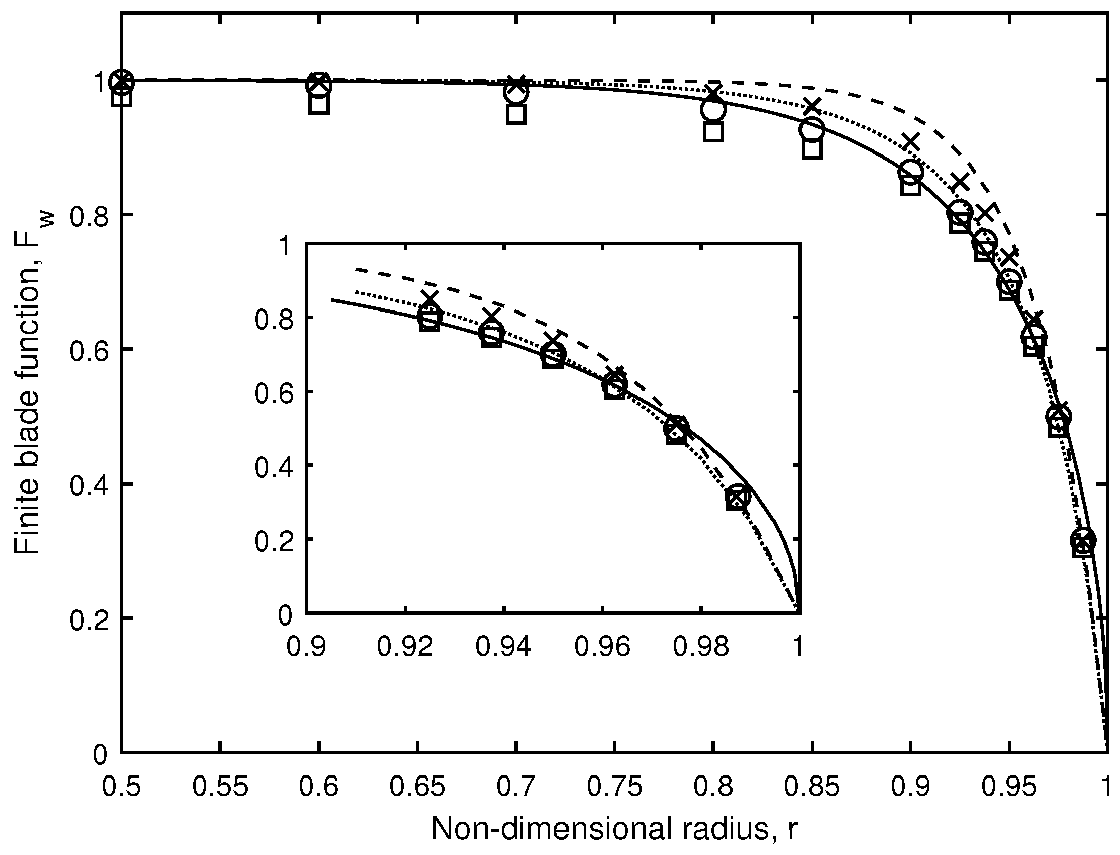
F u computed from Equation (16) and F w determined similarly from the Biot-Savart law for typical values of N = 3 and tip speed ratio λ = 7.13 , for which p = 0.10 , are shown as circles in Figure 1 and Figure 2 respectively. They are the “target” results from the full Biot-Savart integration. Note the lines showing Prandtl’s tip loss factor, F P , which is assumed to equal F u and F w , and the FBFs are the same in both figures because F u = F w from the KH equations with constant p. Only the results from the outer half of the blade ( r 0.5 ) are plotted. Clearly F u differs from F w in expanding flow and F u from (6) is significantly more accurate than F P but the reverse is true for the azimuthal FBF, F w , in general. The revised form of F w , determined as explained below and shown as the dotted line, is, however, more accurate than F P for r > 0.9 .
To explore more fully the different behaviours of F u and F w compared to Equation (6), both figures show the FBFs determined for a helical spiral having the local vortex surface/streamsurface slope at the rotor:
t = 1 + k * β , where k * = k ( R 1 ) .
for the tip vortex. The implication of the figures is that F w near the tip, but not F u , is determined largely by the slope of the bounding streamsurface. This is not surprising given the form of the denominator in (11) makes F u unbounded when the vortex trajectory is a spiral. The significance of the local induction for F w is shown further by the very small effect of reducing the upper limit on the numerical integration from 1000 π to 2 π which implies that only the vortex attached to the blade on which w b is being calculated, has a large effect on F w . Although not shown here, the dominance of local induction occurs also for v and v b and hence F v , which is considered in the next subsection.
If the integrand for F w is determined largely by the closest vortex and its slope, it follows from Equations (10) and (11) that
i w , b ( r ) d 3 p r cos ( β ) β sin ( β ) k * β 2 sin ( β ) r 2 + 1 2 r cos ( β ) + p 2 + k * 2 β 2 + 2 k * β 1 r cos ( β ) 3 / 2 .
Further, by ignoring the last term in the numerator and denominator on the grounds that both are of order β 3 as r 1 , then
i w , b ( r ) d 3 p r cos ( β ) β sin ( β ) r 2 + 1 2 r cos ( β ) + p 2 + k * 2 β 2 3 / 2 .
The factor multiplying p in Equation (18) is identical to i w , b for a vortex of constant radius, t = 1 , at the “equivalent pitch” of p * = p 2 + k * 2 . This changes the equation for F w from Equation (6) to
F w = 1 / 1 2 p S 1 , b ( p * ) ( N p * 2 ) .
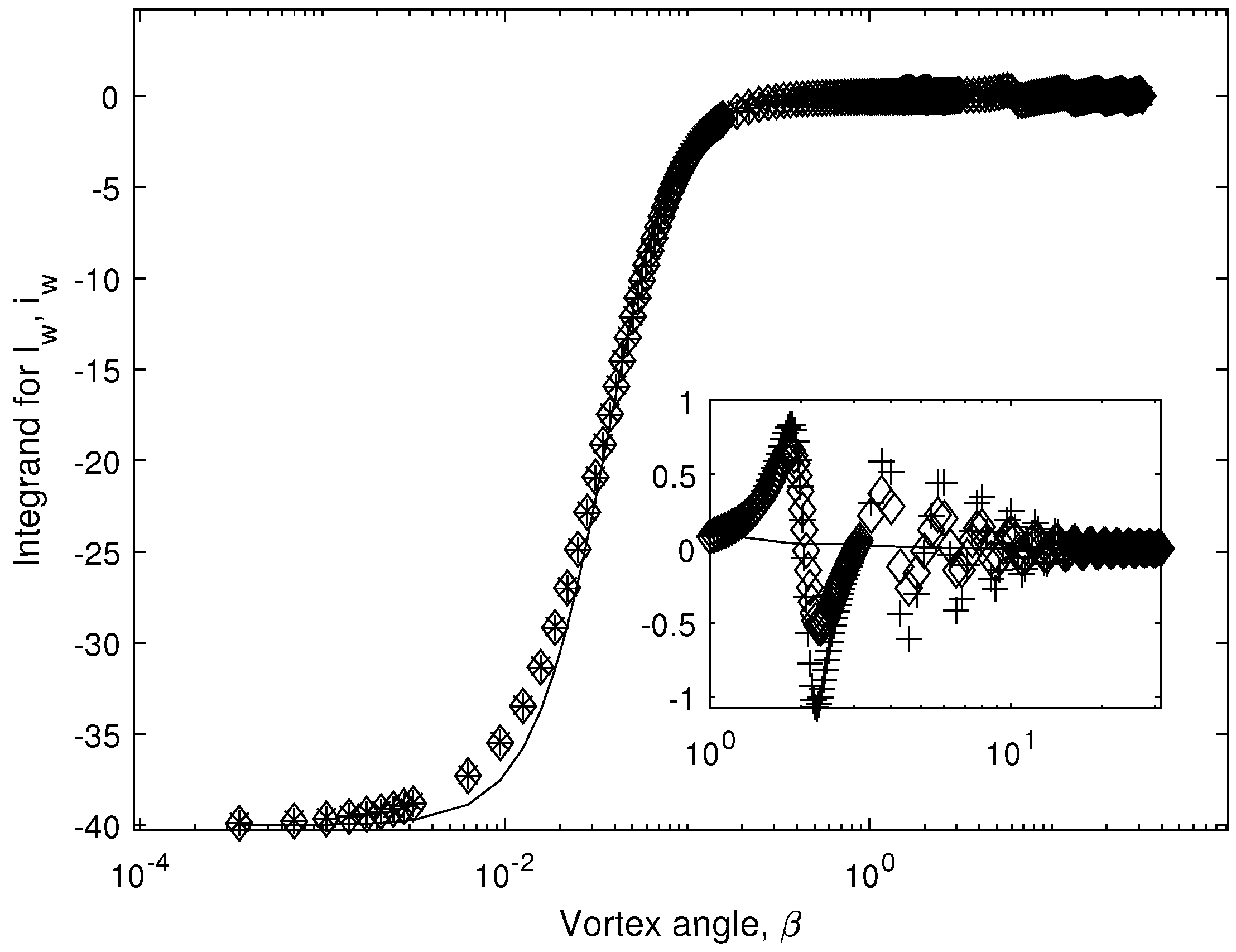
Figure 3 demonstrates the accuracy of the approximations leading to (20) for r = 0.95 . The equivalent pitch integrand in (19) has the same asymptote as β 0 but is less accurate for β around 10 2 . The inset shows that it does not capture the effects of the vortices trailing from the other blades but the error is small.
The dependence of the modified pitch on the expansion requires numerical values of v which are normally not computed in blade element analyses. One solution is to assume u v near the tip where the finite blade functions are most important so that k * can be approximated as k * ( r ) u ( r ) / 1 u ( r ) . If u 1 / 3 at high λ , then k * 0.5 and so k * 2 can dominate p 2 as it does for the values in Table 1.

3.2. The Radial Velocity and F v

Neither the angular momentum equation nor the conventional axial momentum equation for the flow through the rotor contain v. It does appear in the impulse-based derivation of the axial momentum equation by Limacher and Wood [3] but is removed by the assumptions of continuity through the rotor and the near-zero value of the expansion integral. Wood and Limacher [16] show that the part of the expansion integral covering the rotor is equal to the contribution to the axial thrust on the rotor due to the pressure acting on the expanding upwind flow, Δ C T . When N is large, Δ C T , is given by
Δ C T = 2 0 1 0 2 π u 2 v 2 r d r .
For p = 0.1 in Table 1, Δ C T = 0.061 which is 7% of C T = 0.866 . This suggests that more advanced and more accurate BEMT methods in the future will need to compute v and F v . Figure 4 shows F v for the conditions of Table 1 with p = 0.1 compared to that for a non-expanding tip vortex. v ( r , θ ) is clearly more uniform in expanding flow and F v deviates from unity much less than F u and F w .
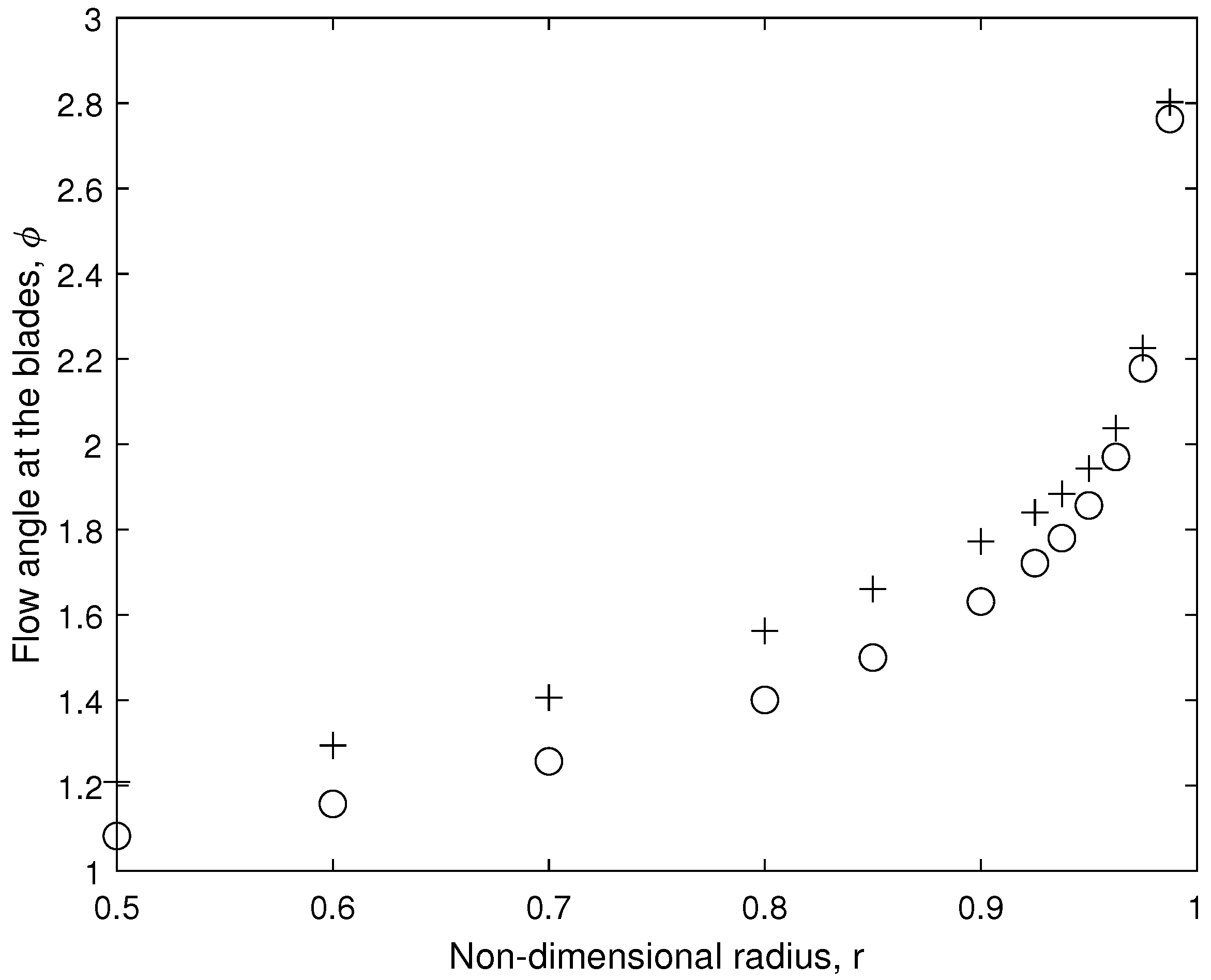
One further aspect of non-zero v is that it causes the blades to act like swept wings where the flow is not parallel to the chord in Figure 5. It is well-known from swept wing analsys that this alters the lift and drag. The “sweep” angle ϕ between v b and the ( θ , z ) plane rotor flow is
ϕ = tan 1 v b / ( 1 u b ) 2 + ( λ r + w b ) 2 .
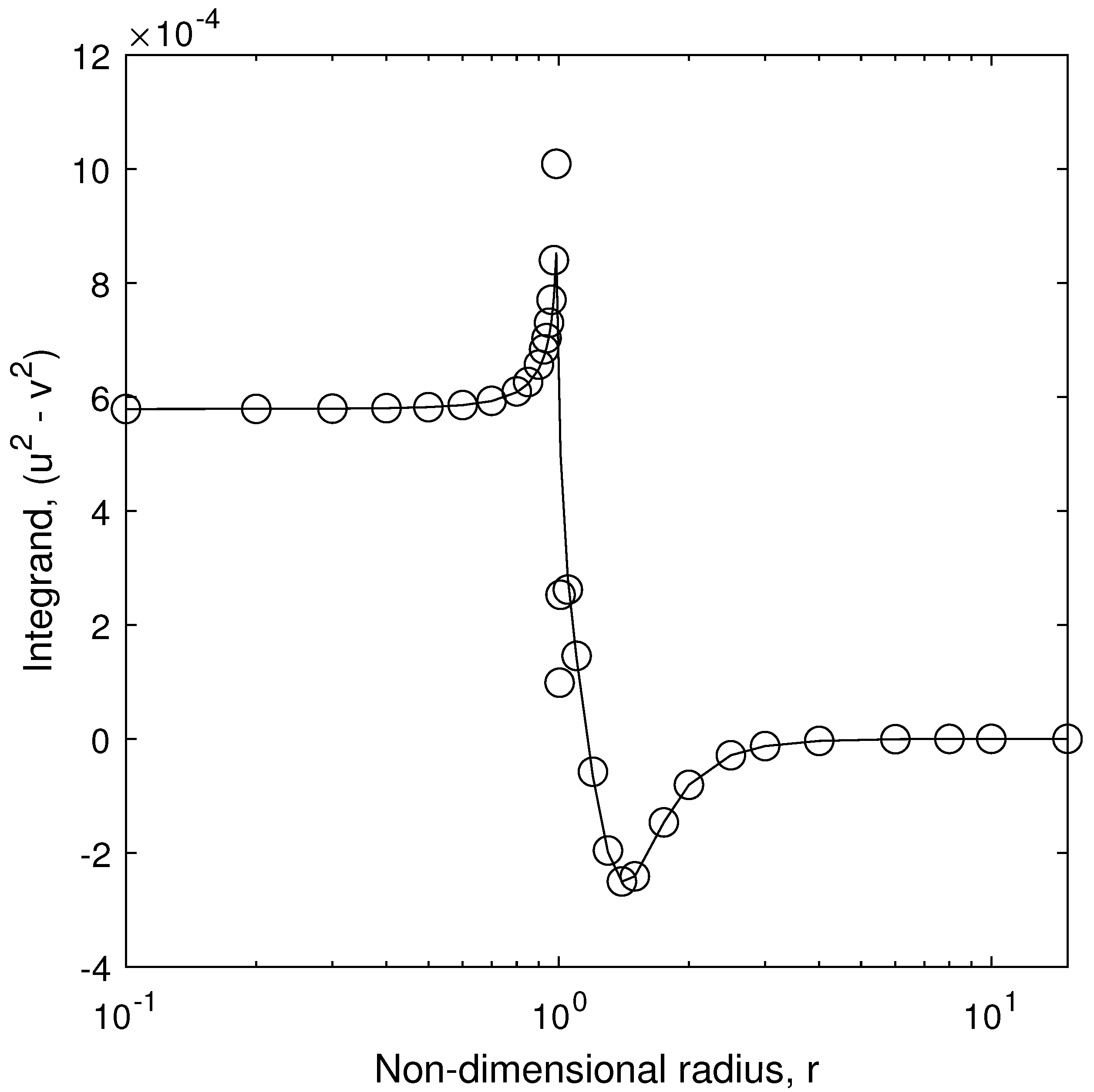
The integrand for the expansion integral, u 2 v 2 , is shown for the conditions of Table 1 and p = 0.1 in Figure 6. The θ integrals used the trapezoidal rule with 360 equal azimuthal increments. The same rule was used for the radial integral to find Δ C T . There are apparent errors due to the singularities at x = 1 but it is reasonable to conclude that the only significant difference between the square of the averaged velocities and the average of the squares has little effect on Δ C T or the expansion integral. Generally, the azimuthal variations in u ( θ ) are significantly less than those for the other two velocity components.

4. Conclusions

This study considered the ways in which significant expansion of the wake at high tip speed ratios, influences the finite blade functions used in blade element/momentum theory for horizontal-axis wind turbines. These functions can be estimated very quickly and simply using Prandtl’s well-known tip loss factor, or they can be calculated using accurate approximations to the Kawada-Hardin equations for the velocity field of helical vortices of constant radius and pitch.
The first aim was to assess the accuracy of the constant-radius equations by using the Biot-Savart law to find the functions for a tip vortex of constant pitch but increasing radius. This was done on the grounds that radius is likely to change more rapidly than the pitch. The study was limited to tip speed ratios in excess of 7 where Prandtl’s factor should be most accurate. It was found that expansion has little effect on the finite blade function for the axial flow which was generally more accurate than Prandtl’s factor, but had an effect on the azimuthal function that depended on the expansion. A simple correction for expansion was shown to provide a function that was more accurate than Prandtl’s, at least near the tip.
The second aim of the work was to investigate further the radial velocity and its circumferential variation. Although its magnitude equals that of the axial velocity, v is not large enough to require corrections to the lift and drag used in blade element analysis, and it varies less with azimuth than the other velocities. It has a small effect on the rotor thrust through Equation.

Funding

This work is part of a research project on wind turbine aerodynamics funded by the NSERC Discovery Program.

Data Availability Statement

The Matlab codes used to derive the results in this paper are available from the author.

Conflicts of Interest

The author declares that he has no competing interests.

References

  1. Hansen, M.O.L. Aerodynamics of Wind Turbines, 2nd ed.; Earthscan: London, UK, 2015. [Google Scholar]
  2. Schmitz, S. Aerodynamics of Wind Turbines: A Physical Basis for Analysis and Design; John Wiley & Sons: Hoboken, NJ, USA, 2020. [Google Scholar]
  3. Limacher, E.J.; Wood, D.H. An impulse-based derivation of the Kutta-Joukowsky equation for wind turbine thrust. Wind Energy Sci. 2021, 6, 191–201. [Google Scholar] [CrossRef]
  4. Glauert, H. Aerodynamic Theory: Division L, Airplane Propellers; Springer: Berlin/Heidelberg, Germany, 1935; Chapter XI. [Google Scholar]
  5. Shen, W.Z.; Mikkelsen, R.; Srensen, J.N.; Bak, C. Tip vortex corrections for wind turbine computations. Wind Energy 2005, 8, 457–475. [Google Scholar] [CrossRef]
  6. Pirrung, G.R.; Van der Laan, M.P.; Ramos-García, N.; Meyer Forsting, A.R. A simple improvement of a tip loss model for actuator disc simulations. Wind Energy 2020, 23, 1154–1163. [Google Scholar] [CrossRef]
  7. Epps, B. On the rotor lifting line wake model. J. Ship Prod. Des. 2017, 57, 181–201. [Google Scholar] [CrossRef]
  8. Wood, D.H.; Okulov, V.L.; Bhattacharjee, D. Direct calculation of wind turbine tip loss. Renew. Energy 2016, 95, 269–276. [Google Scholar] [CrossRef] [Green Version]
  9. Wood, D.H.; Okulov, V.L.; Vaz, J.R.P. Calculation of the induced velocities in lifting line analyses of propellers and turbines. Ocean. Eng. 2021, 235, 109337. [Google Scholar] [CrossRef]
  10. Wimshurst, A.; Willden, R.H.J. Analysis of a tip correction factor for horizontal axis turbines. Wind Energy 2017, 20, 1515–1528. [Google Scholar] [CrossRef]
  11. Schmitz, S.; Maniaci, D.C. Methodology to determine a tip-loss factor for highly loaded wind turbines. AIAA J. 2017, 55, 341–351. [Google Scholar] [CrossRef]
  12. Wimshurst, A.; Willden, R.H.J. Computational observations of the tip loss mechanism experienced by horizontal axis rotors. Wind Energy 2018, 21, 544–557. [Google Scholar] [CrossRef]
  13. Wimshurst, A.; Willden, R. Spanwise flow corrections for tidal turbines. Int. Mar. Energy J. 2018. [Google Scholar] [CrossRef]
  14. Vaz, J.R.; Okulov, V.L.; Wood, D.H. Finite blade functions and blade element optimization for diffuser-augmented wind turbines. Renew. Energy 2021, 165, 812–822. [Google Scholar] [CrossRef]
  15. Van Kuik, G.A. On the velocity at wind turbine and propeller actuator discs. Wind Energy Sci. 2020, 5, 855–865. [Google Scholar] [CrossRef]
  16. Wood, D.H.; Limacher, E.L. Some effects of flow expansion on the aerodynamics of horizontal-axis wind turbines. Wind Energy Sci. Discuss. 2021, 1–21. [Google Scholar] [CrossRef]
  17. Kawada, S. Induced velocity by helical vortices. J. Aeronaut. Sci. 1936, 36, 86–87. [Google Scholar] [CrossRef]
  18. Hardin, J.C. The velocity field induced by a helical vortex filament. Phys. Fluids 1982, 25, 1949–1952. [Google Scholar] [CrossRef]
  19. Kawada, S. Calculation of Induced Velocity by Helical Vortices and Its Application to Propeller Theory; Technical Report 172; Aeronautical Research Institute, Tokyo Imperial University: Tokyo, Japan, 1939; Available online: http://repository.tksc.jaxa.jp/pl/dr/IS4146951000/en (accessed on 1 November 2021).
  20. Fukumuto, Y.; Okulov, V.L.; Wood, D.H. The contribution by Kawada to the analysis of the velocity induced by a helical vortex filament. Appl. Mech. Rev. 2015, 674, 060801-1–060801-6. [Google Scholar] [CrossRef]
  21. Okulov, V.L.; Sørensen, J.N. The self-induced motion of a helical vortex. J. Fluid Mech. 2020, 883. [Google Scholar] [CrossRef]
  22. Okulov, V.L. On the stability of multiple helical vortices. J. Fluid Mech. 2004, 521, 319–342. [Google Scholar] [CrossRef]
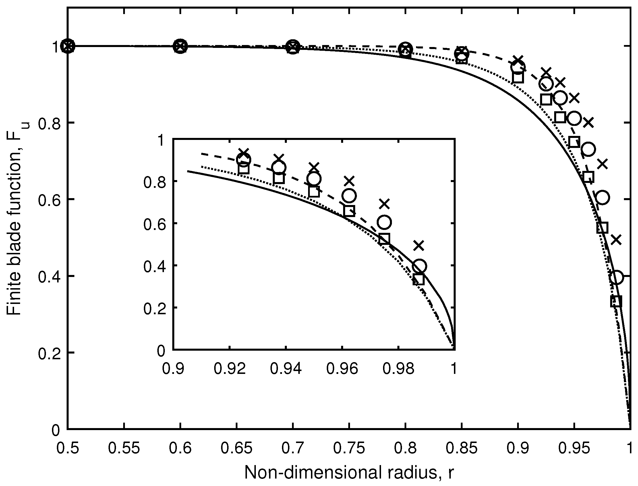
Figure 1. Axial finite blade function, F u for conditions in Table 1, p = 0.1 . Solid line shows F P , dashed line is F u = F w from the Kawada-Hardin Equation (6), and dotted line, F u = F w from the modified pitch Equation (20). ◯ shows Biot-Savart calculation with Equation (12); ×, Biot-Savart calculation with Equation (17) and upper limit 1000 π ; □ Biot-Savart calculation with Equation (17) but upper limit = 2 π .
Energies 14 07653 g001
Figure 2. Circumferential finite blade function, F w for conditions in Table 1, p = 0.1 . Solid line shows F P , dashed line is F u = F w from the Kawada-Hardin Equation (6), and dotted line, F u = F w from the modified pitch Equation (20). ◯ shows Biot-Savart calculation with Equation (12); ×, Biot-Savart calculation with Equation (17) and upper limit 1000 π ; □ Biot-Savart calculation with Equation (17) but upper limit = 2 π .
Energies 14 07653 g002
Figure 3. Integrand for I w for N = 3 , p = 0.1 , λ = 7.13 and r = 0.95 . i w from Equation (12) for all blades, ×; for Equation (12) and first blade only, +; for Equation (17) and all blades, ⋄. Solid line shows i w from Equation (19).
Energies 14 07653 g003
Figure 4. Radial finite blade function, F v from Biot-Savart calculation with Equation (12) for conditions in Table 1, p = 0.1 ; ◯. F v for p = 0.1 but constant t = 1 , ×.
Energies 14 07653 g004
Figure 5. Flow angle, ϕ ,(in degrees) at the blades for the conditions of Figure 4.
Energies 14 07653 g005
Figure 6. u 2 v 2 for p = 0.1 in Table 1. Circles show integrand using u and v, solid line shows integrand from u ( θ ) and v ( θ ) . Note that the x scale is logarithmic.
Energies 14 07653 g006
Table 1. Results for the expanding Joukowsky wake with constant pitch. N = 3 .
p R 2 k λ C P C T
0.101.5970.49477.130.5570.866
0.051.5920.248214.280.5560.864
Publisher’s Note: MDPI stays neutral with regard to jurisdictional claims in published maps and institutional affiliations.