Article

A Dual Resonance Electromagnetic Vibration Energy Harvester for Wide Harvested Frequency Range with Enhanced Output Power

School of Electrical and Electronic Engineering, Huazhong University of Science and Technology, Wuhan 430074, China
*
Author to whom correspondence should be addressed.
Energies 2021, 14(22), 7675; https://doi.org/10.3390/en14227675
Submission received: 29 August 2021 / Revised: 8 November 2021 / Accepted: 8 November 2021 / Published: 16 November 2021
(This article belongs to the Special Issue Advanced Energy Harvesting Technologies)

Abstract

:
A dual resonance vibration electromagnetic energy harvester (EMEH) is proposed in this paper to extend frequency range. Compared with the conventional dual resonance harvester, the proposed system realizes an enhanced “band-pass” harvesting characteristic by increasing the relative displacement between magnet and coil among two resonance frequencies with a significant improvement in the average harvested power. Furthermore, two resonant frequencies are decoupled in the proposed system, which leads to a more straightforward design. The proposed dual resonance EMEH is constructed with a tubular dual spring-mass structure. It is designed with a serpentine planar spring and the coil position is optimized for higher power density with an overall size of 53.9 cm3 for the dual resonance EMEH. It realizes an output power of 11 mW at the first resonant frequency of 58 Hz, 14.9 mW at the second resonant frequency of 74.5 Hz, and 0.52 mW at 65 Hz, which is in the middle of the two resonance frequencies. The frequency range of output power above 0.5 mW is from 55.8 Hz to 79.1 Hz. The maximum normalized power density (NPD) reaches up to 2.77 mW/(cm3·g2). Compared with a single resonance harvester design under the same topology and outer dimension at a resonant frequency of 74.5 Hz, the frequency range in the proposed EMEH achieves more than a 2× times extension. The proposed dual resonance EMEH also has more than 2 times wider frequency range than other state-of-art wideband EMEHs. Therefore, the proposed dual resonance EMEH is demonstrated in this paper for a high maximum NPD and higher NPD over a wide frequency range.

1. Introduction

Vibration energy harvesting (EH) converts ambient vibration energy into electrical energy, which is regarded as a premium technology to replace batteries to power wireless sensors [1,2,3]. An electromagnetic energy harvester (EMEH) extracts electricity through the induced electromotive force generated by the relative displacement between the magnet and the coil [4,5,6]. Traditional EMEHs usually have a single resonant frequency, through which the maximum displacement can be achieved, and a maximum harvested power is realized. However, when vibration frequency deviates from the resonant frequency, the harvested power drops dramatically [7,8,9], as shown in Figure 1. Actual vibrations in the environment always have wide dynamic range. For example, the main vibration frequencies of a pile head excited by a train passing through a tunnel vary between 50 and 80 Hz [10]. It is hard to keep the single resonance EH system constantly operating at the optimal point [11]. To maintain sufficient harvested power, extending the frequency coverage for EMEH is vital.
Several techniques have been explored to realize wide frequency range for EMEHs. EH arrays were adopted in [12,13] by combining multi-narrow-band harvesters into a board-band system at the cost of large volume and weight. Sufficient space must be guaranteed among different subsystems to avoid mutual influences, which further reduces overall power density. Resonant frequency tuning technology in [14] employed an additional unit to adjust the stiffness of the spring to match with excitation frequency, which brought in extra power losses and increased volume. Nonlinear characteristics in mechanical–electrical conversion utilized a non-linear system force to produce non-linear dynamic responses for harvested frequency extension. For example, [15,16] used nonlinear springs to extend the frequency range, but it was relatively narrow. The bi-stable harvesters in [17,18] had two stable equilibrium positions and would generate higher power when translators oscillated between the two potential wells. However, such architectures are either complicated for actual practices or with still limited frequency range. The up-conversion harvesters in [19,20] converted low-frequency vibration into high-frequency vibration through internal collisions. Due to the inevitable energy loss in the collision process, it was not clear whether the output power can be effectively increased. Continuous collisions will also reduce system reliability. Hybrid harvesters, such as piezoelectric–electromagnetic mechanisms, are also effective in both improving energy conversion efficiency and expanding bandwidth [21,22,23], which are usually realized through nonlinear effects [24] or multi-resonance structures [25,26].
Dual resonance technology combines two resonators to form two resonant frequencies [27,28,29,30], as depicted as the dashed line in Figure 1. Although this approach is straightforward, it contains significant limitations as the two resonant frequencies were cross-affected and were quite apart from each other. Hence, the harvested power was quite low in the region in between the two resonant frequencies and it is unrealistic to construct a high power “band-pass” harvester.
In this paper, an EMEH with dual uncoupled resonant frequencies is proposed to form a “band-pass” type of wide harvesting frequency range. The structure of the paper is organized as follows: Section 2 describes the basic topology of the proposed system and its frequency domain characteristics; Section 3 compares the design of dual resonant frequencies with a conventional dual resonance EMEH; the prototype of the proposed EMEH and measurement results are given in Section 4; and, finally, a conclusion is drawn in Section 5.

2. Basic Theorem and Frequency Range Extension of the Proposed Dual Resonance EMEH

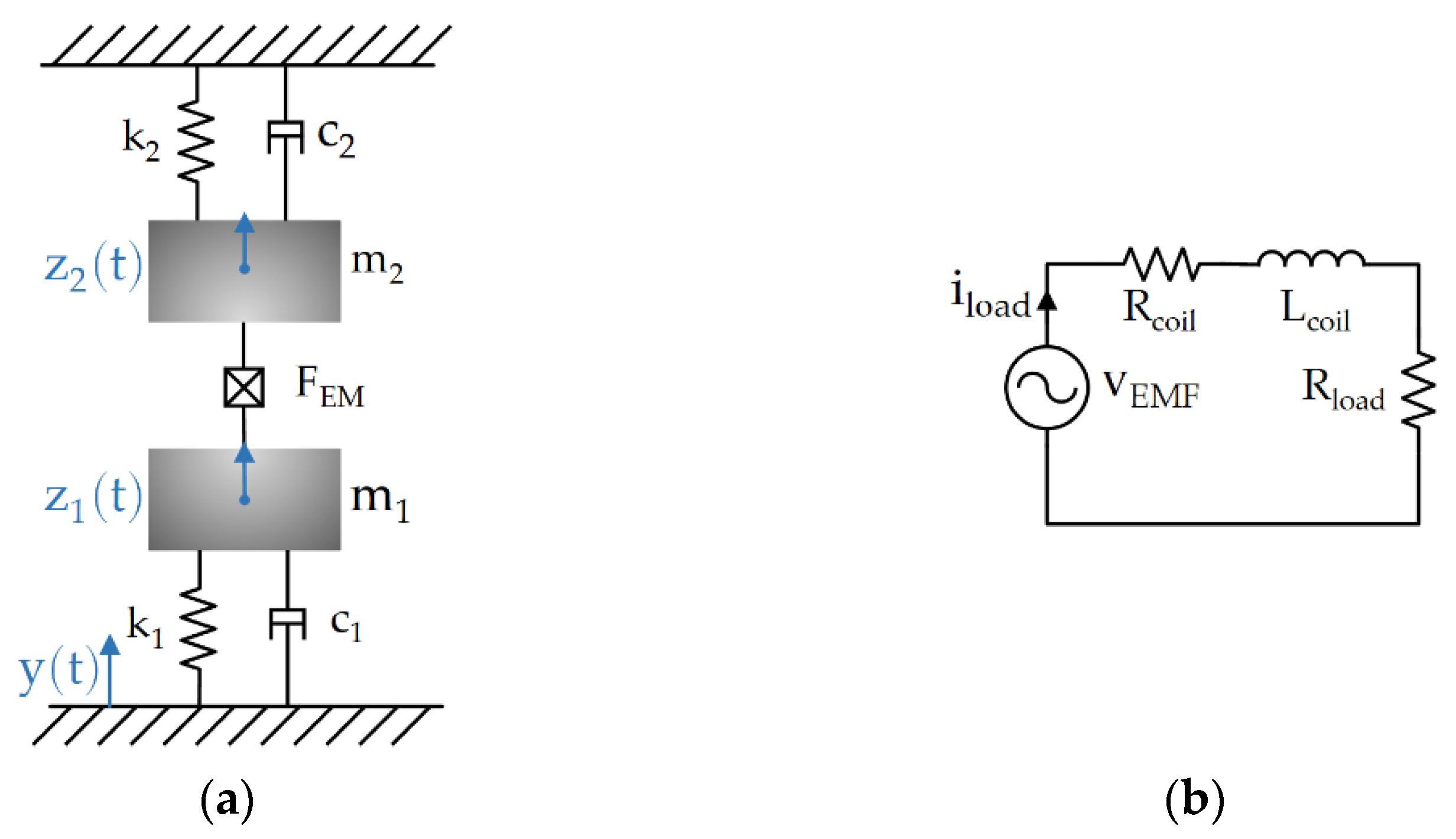
The basic architecture of the proposed energy harvester is presented in Figure 2a. Mass m 1 and m 2 are composed by a nonmagnetic mass and a permanent magnet, respectively. The translators are connected to two springs and are designed for different resonant frequencies. When one translator oscillates relatively to the other, induced current is generated in the coil. According to Newton’s second law of motion, the system’s dynamic mechanical domain equations are established as:
z ¨ 1 ( t ) + c 1 m 1 z · 1 ( t ) + k 1 m 1 z 1 ( t ) = y ¨ ( t )     K e i load ( t ) m 1
z ¨ 2 ( t ) + c 2 m 2 z · 2 ( t ) + k 2 m 2 z 2 ( t ) = y ¨ ( t ) + K e i load ( t ) m 2
where z 1 ( t ) and z 2 ( t ) are the relative displacement of the two translators; c 1 and c 2 are the mechanical damping of the two translators; k 1 and k 2 are the spring stiffness coefficients; y is the displacement of excitation source; K e is the electromechanical transduction constant; and K e i load ( t ) is the electromagnetic force, equaling to F EM [31]. Figure 2b shows the fundamental equivalent circuit of the proposed EMEH, where the induced electromagnetic voltage v EMF ( t ) can be derived as:
v EMF ( t ) = K e ( z · 1 z · 2 ) = L coil i · load ( t ) + R t i load ( t )
where R coil and L coil are the coil resistance and inductance; i load is the loop current; R load is the equivalent input resistance of the interface circuit; and R t represents the summation of R coil and R load . As ω vib L coil is much smaller than R t , L coil is neglected in the following analysis. The electromagnetic damping to the translator is derived as c e = K e 2 / R t [1,7,8]. To understand the frequency responses of the system, the transfer functions of the relative displacements to the output are defined as: H 1 ( s ) = Z 1 ( s ) / Y ( s ) , H 2 ( s ) = Z 2 ( s ) / Y ( s ) , and H ( s ) = [ Z 1 ( s )   Z 2 ( s ) ] / Y ( s ) .
With the assumption of a sinusoidal vibration source, i.e., y ( t ) = Y max sin ω vib t , and with a small displacement to ensure linearity in the spring, the displacement of two translators and overall displacements can be expressed as:
z 1 ( t ) = | H 1 ( j ω vib ) | Y max sin ( ω vib t + arg ( H 1 ( j ω vib ) ) )
z 2 ( t ) = | H 2 ( j ω vib ) | Y max sin ( ω vib t + arg ( H 2 ( j ω vib ) ) )
z ( t ) = z 1 ( t )     z 2 ( t ) = | H ( j ω vib ) | Y max sin ( ω vib t + arg ( H ( j ω vib ) ) )
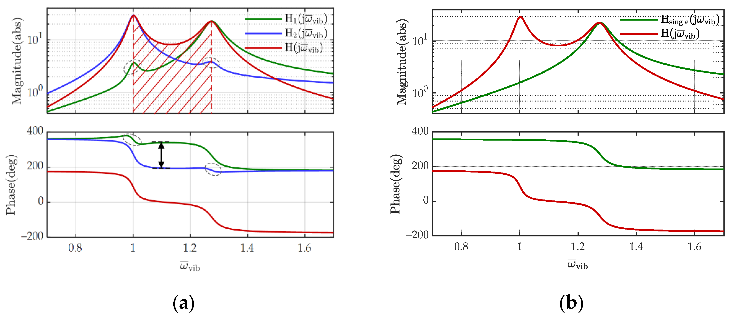
For convenient comparisons, transfer functions are transformed into the frequency domain and normalized by ω ¯ vib = ω vib / ω 1 , as expressed in (7–9). ω 1 and ω 2 are the natural angular frequencies of resonators 1 and 2, which can be expressed as k 1 / m 1 and k 2 / m 2 , respectively. ξ 1 and ξ 2 are the mechanical damping ratios of resonators 1 and 2 as c 1 / 2 m 1 ω 1 and c 2 / 2 m 2 ω 2 , correspondingly. ξ e 1 and ξ e 2 are the electromagnetic damping ratios of resonators 1 and 2 as c e / 2 m 1 ω 1 and c e / 2 m 2 ω 2 , respectively. α is the second natural angular frequency over the first natural angular frequency, as ω 2 / ω 1 . The frequency response of the dual resonance EMEH is studied with ξ 1 = 0.004 , ξ 2 = 0.0051 , ξ e 1 = 0.0173 , ξ e 2 = 0.0134 , and α = 1.28 , where the parameters are selected as follows: c 1 = c 2 = 0.22   N s / m , m1 = 76 g, m2 = 46 g, ce = 0.74   N s / m , ω 1 = 364   rad / s , and ω 2 = 465   rad / s . The above parameters were chosen based upon the actual prototype designs that will be further discussed in Section 4; c 1 and c 2 were measured by Panasonic’s laser sensor HL-C235. The frequency-domain characteristics of the transfer functions are plotted in Figure 3a. When one resonator works under resonance frequency, the other resonator is also affected by coupled electromagnetic force and produces a small output spike, as circled in Figure 3a. In the region of 1 < ω ¯ vib < 1.28 , the magnitude of H ( j ω ¯ vib ) equals to the summation of | H 1 ( j ω ¯ vib ) | and | H 2 ( j ω ¯ vib ) | . This is because the angular difference between H 1 ( j ω ¯ vib ) and H 2 ( j ω ¯ vib ) is almost 180°. The high harvested power in the harvested frequency band is one main advantage of this proposed dual resonance EMEH. A single resonance EMEH is also analyzed under the same parameters and with only one translator of normalized resonant angular frequency 1 . 28 , as depicted in Figure 3b. The normalized frequency range of magnitude above 8 in the dual resonance EMEH is from 0.953 to 1.336 and is from 1.207 to 1.36 for the single resonance EMEH. The frequency coverage range in the dual resonance EMEH is more than 2.5 times of that in the single resonance EMEH, and therefore more output power can be harvested with extended frequency ranges. The model of the proposed EMEH and the above analysis were carried out under the assumptions of the small displacement and linear movements of the spring. If a large deformation happens, the spring will generate non-linear effects that vary the frequency responses.
H 1 ( j ω ¯ vib ) = ( j ω ¯ vib ) 2 [ ω ¯ vib 2 + 2 ( ξ 2 α + ξ e 2 α + ξ e 1 ) j ω ¯ vib + α 2 ] [ ω ¯ vib 2 + 2 ( ξ 1 + ξ e 1 ) j ω ¯ vib + 1 ] [ ω ¯ vib 2 + 2 α ( ξ 2 + ξ e 2 ) j ω ¯ vib + α 2 ] + 4 ξ e 1 ξ e 2 α ω ¯ vib 2
H 2 j ω ¯ vib =   ( j ω ¯ vib ) 2 [ ω ¯ vib 2 + 2 ( ξ 1 + ξ e 1 + ξ e 2 α ) j ω ¯ vib + 1 ] [ ω ¯ vib 2 + 2 ( ξ 1 + ξ e 1 ) j ω ¯ vib + 1 ] [ ω ¯ vib 2 + 2 α ( ξ 2 + ξ e 2 ) j ω ¯ vib + α 2 ] + 4 ξ e 1 ξ e 2 α ω ¯ vib 2
H ( j ω ¯ vib ) =   ( j ω ¯ vib ) 2 [ 2 ( ξ 2 α     ξ 1 ) j ω ¯ vib + α 1 2   1 ] [ ω ¯ vib 2 + 2 ( ξ 1 + ξ e 1 ) j ω ¯ vib + 1 ] [ ω ¯ vib 2 + 2 α ( ξ 2 + ξ e 2 ) j ω ¯ vib + α 2 ] + 4 ξ e 1 ξ e 2 α ω ¯ vib 2

3. Resonant Angular Frequency of the Dual Resonance Electromagnetic EH

The resonant angular frequencies of the proposed system are defined as ω n 1 and ω n 2 , and further normalized as ω ¯ n 1 ω n 1 / ω 1 and ω ¯ n 2 ω n 2 / ω 1 , respectively. Equation (10) can be derived by ignoring the electromagnetic and mechanical damping ratios in Equation (9), and the normalized resonance angular frequencies of the proposed dual resonance EMEH can be extracted as ω ¯ n 1 = 1 and ω ¯ n 1 = 2 = α = ω 2 / ω 1 :
( ω ¯ vib 2 + 1 ) ( ω ¯ vib 2 + α 2 ) = 0
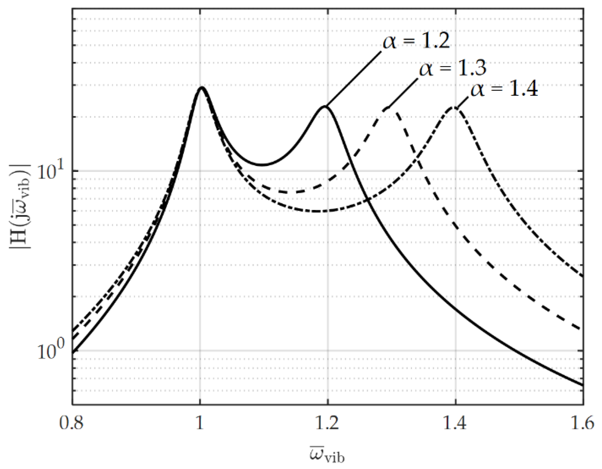
Figure 4 shows the magnitude frequency characteristic of H ( j ω ¯ vib ) under different α . The higher α is, the further apart from each other two resonant frequencies are. Therefore, the actual resonance frequencies of the proposed EMEH can be adjusted by the natural angular frequencies of the resonators through spring and mass designs, which follow ω n 1 = ω 1 = k 1 / m 1 and ω n 2 = ω 2 = k 2 / m 2 . The two resonant frequencies of the proposed EMEH are decoupled and have independent freedom to adjust.
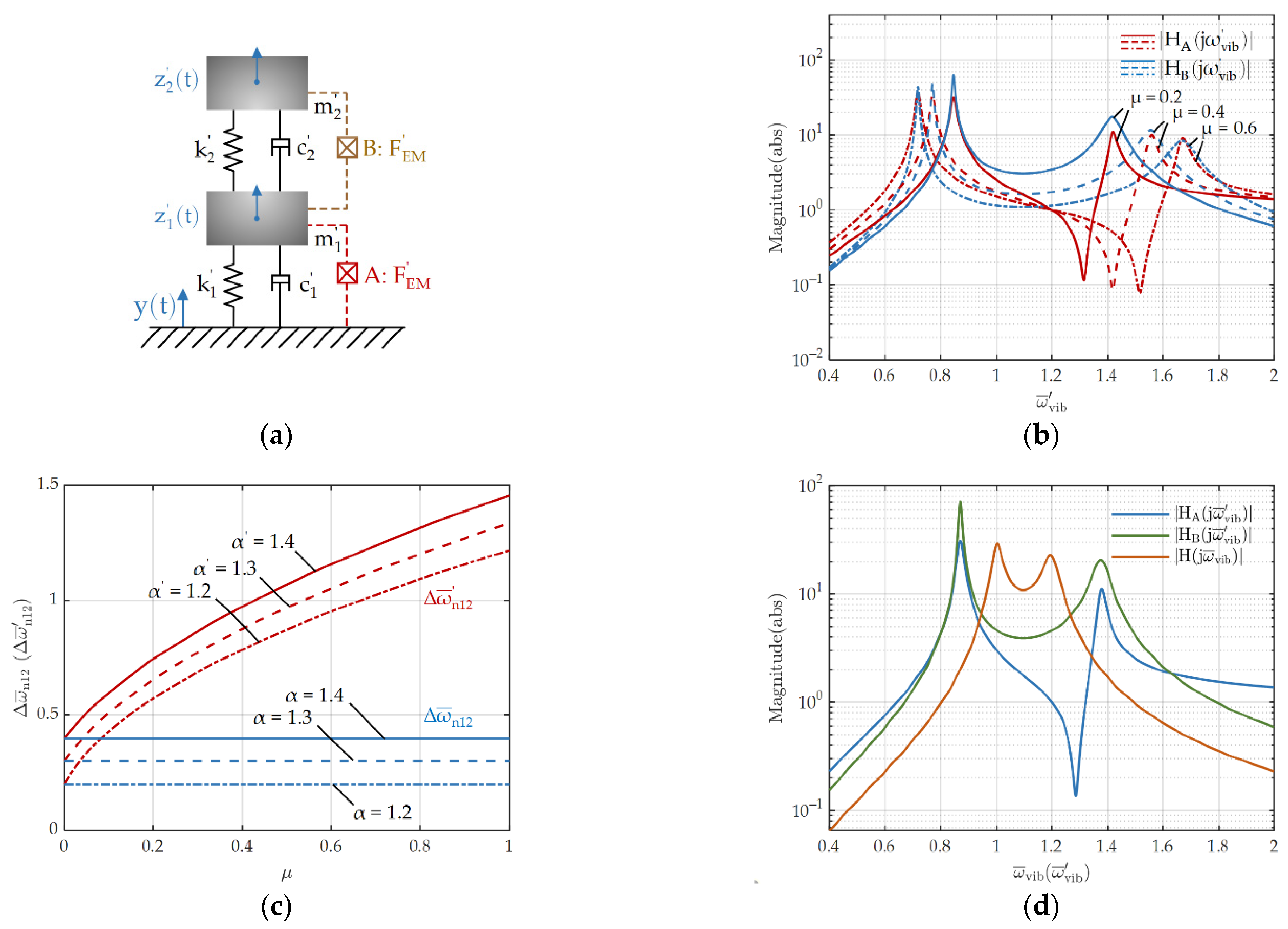
To further demonstrate this feature, the resonant frequencies for a conventional dual resonant EMEH were studied and compared with the proposed system. As depicted in Figure 5a, the accessory resonator in a conventional dual resonant EMEH is connected to the main resonator through the spring. The transducer can be placed in 2 positions: between mass 1 and the frame, as configuration A, and between mass 1 and mass 2, as configuration B [32]. The dynamic mechanical domain equations are established as shown in Equations (11) and (12) [32,33], where z 1 ( t ) and z 2 ( t ) are the relative displacement; c 1 and c 2 are the mechanical damping; k 1 and k 2 are the spring stiffness coefficients; y is the displacement of the excitation source; F EM is the electromagnetic force; and m 1 and m 2 are the masses of the two translators in the conventional system, respectively. The transfer functions for the conventional dual resonant EMEH are expressed as H A ( s ) = Z 1 ( s ) / Y ( s ) , for configuration A, and H B ( s ) = [ Z 1 ( s )   Z 2 ( s ) ] / Y ( s ) , for configuration B. The frequency domain transfer functions become H A ( j ω ¯ vib ) and H B ( j ω ¯ vib ) , normalized by ω ¯ vib = ω vib / ω 1 , as listed in Equations (13) and (14). The cross-coupling parameter μ is defined as m 2 / m 1 . Under undamped conditions, the resonant angular frequencies of the conventional dual resonant EMEH are derived as shown in Equation (15). The resonant frequencies of the conventional dual resonant EMEH are reliant on the quotient μ of the masses and α . Figure 5b displays that magnitude frequency characteristics of H A ( j ω ¯ vib ) and H B ( j ω ¯ vib ) at α = 1.2 under different μ . It shows that μ has a positive impact on pushing two resonant frequencies apart from each other.
The differences of the two resonance angular frequencies are defined as Δ ω ¯ n 12 = ω ¯ n 1 ω ¯ n 2 , for the conventional dual resonance EMEH, and Δ ω ¯ n 12 = ω ¯ n 1 ω ¯ n 2 , for the proposed system. Figure 5c exhibits the resonance differences under different μ , α , and α . The resonant frequencies of the proposed system are completely unrelated with μ , only depended on the natural angular frequencies of the two resonators. The resonant resonances of the conventional system are highly nonlinearly related to μ . Although the two resonant frequencies of the conventional system are relatively close when μ is small, it is difficult to realize in actual practice. A small μ corresponds to a small m 2 compared with m 1 , resulting in a low k 2 . A spring with low stiffness usually takes up more volume. Figure 5d shows the magnitude frequency characteristic of the transfer functions for the proposed and conventional dual resonance EMEHs at α = α = 1.2 and μ = 0.2 . Compared with the conventional system, the proposed system has two closer resonances and higher magnitudes between resonances.
z ¨ 1 ( t ) =   k 2 m 1 [ z 1 ( t )   z 2 ( t ) ]     c 2 m 1 [ z · 1 ( t ) z · 2 ( t ) ]     k 1 m 1 z 1 ( t )     c 1 m 1 z · 1 ( t )     y ¨ ( t )     K e i load ( t ) m 1
z ¨ 2 ( t ) =   k 2 m 2 [ z 2 ( t )   z 1 ( t ) ]     c 2 m 2 [ z · 2 ( t )     z · 1 ( t ) ]     y ¨ ( t )
H A ( j ω ¯ vib )     ( j ω ¯ vib ) 2 [ j ω ¯ vib 2 + 2 ( 1 + μ ) ξ 2 α j ω ¯ vib + ( 1 + μ ) α 2 ] [ ω ¯ vib 2 + 2 ( ξ 1 + ξ e 1 + μ ξ 2 α ) j ω ¯ vib + 1 + μ α 2 ] [ ω ¯ vib 2 + 2 ξ 2 α j ω ¯ vib + α 2 ]     μ ( 2 ξ 2 α j ω ¯ vib + α 2 ) 2
H B ( j ω ¯ vib )   =   ( j ω ¯ vib ) 2 ( 2 ξ 1 j ω ¯ vib + 1 ) [ ω ¯ vib 2 + ( 2 ξ 1 + 2 μ ( ξ 2 + ξ e 2 ) α ) j ω ¯ vib + 1 + μ α 2 ] [ ω ¯ vib 2 + ( 2 ( ξ 2 + ξ e 2 ) α ) j ω ¯ vib + α 2 ]     μ ( 2 ( ξ 2 + ξ e 2 ) α j ω ¯ vib + α 2 ) 2
ω ¯ n 1 , 2   = 0.707 ( 1 + ( 1 + μ ) α 2 )   ±   1 + ( 1 + μ ) 2 α 2 + 2 ( μ   1 ) α 2

4. Prototype Design and Experiment Verification

4.1. Prototype Design

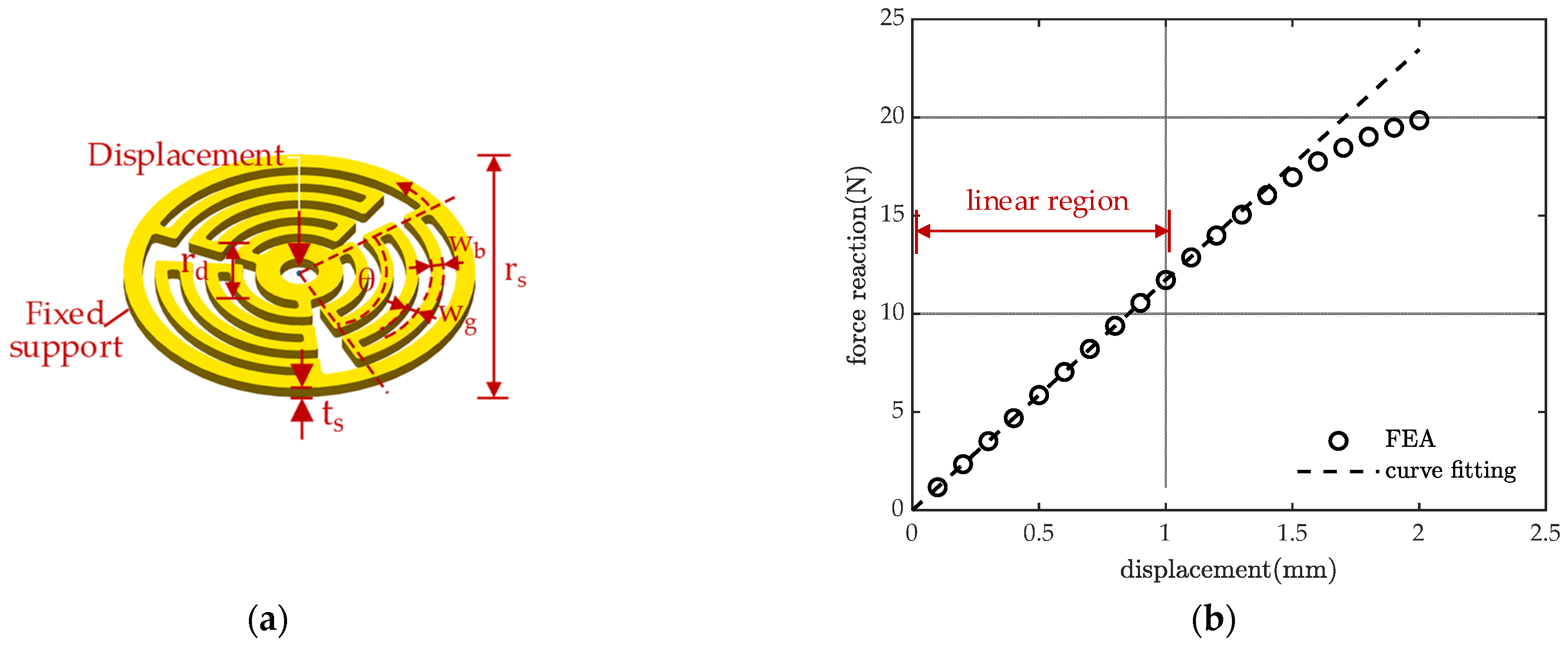
The proposed EMEH is composed by two resonators, one of which resonator is composed by a nonmagnetic mass and a coil, and the other resonator is composed by a permanent magnet. Two masses are connected to the frame though planar springs. The planar spring is composed of multiple serpentine sectors, as plotted in Figure 6a. The serpentine structure allows for lower stiffness and reduces the occupied area. This structure also overcomes the buckling problem caused by the residual stress [34] and further prolongs the reliability of the EMEH. The material of the spring is copper. Finite element analysis (FEA) is employed to determine the stiffness of the spring. When a ramp displacement of 2 mm is applied to the center of the spring, the force reaction is observed and the stiffness is derived as 11,730 N/m, as plotted in Figure 6b. Two identical planar springs were used in the proposed harvester, so that k 1 = k 2 = 11,730   N / m . As discussed in Section 3, the resonant frequencies of the proposed harvester is equal to the natural frequency of the resonator, which can be calculated as f n 1 = 1 / ( 2 π ) k 1 / m 1 = 62.5   Hz and f n 2 = 1 / ( 2 π ) k 2 / m 2 = 80.4   Hz . The key parameters of the dual resonators are listed in Table 1.
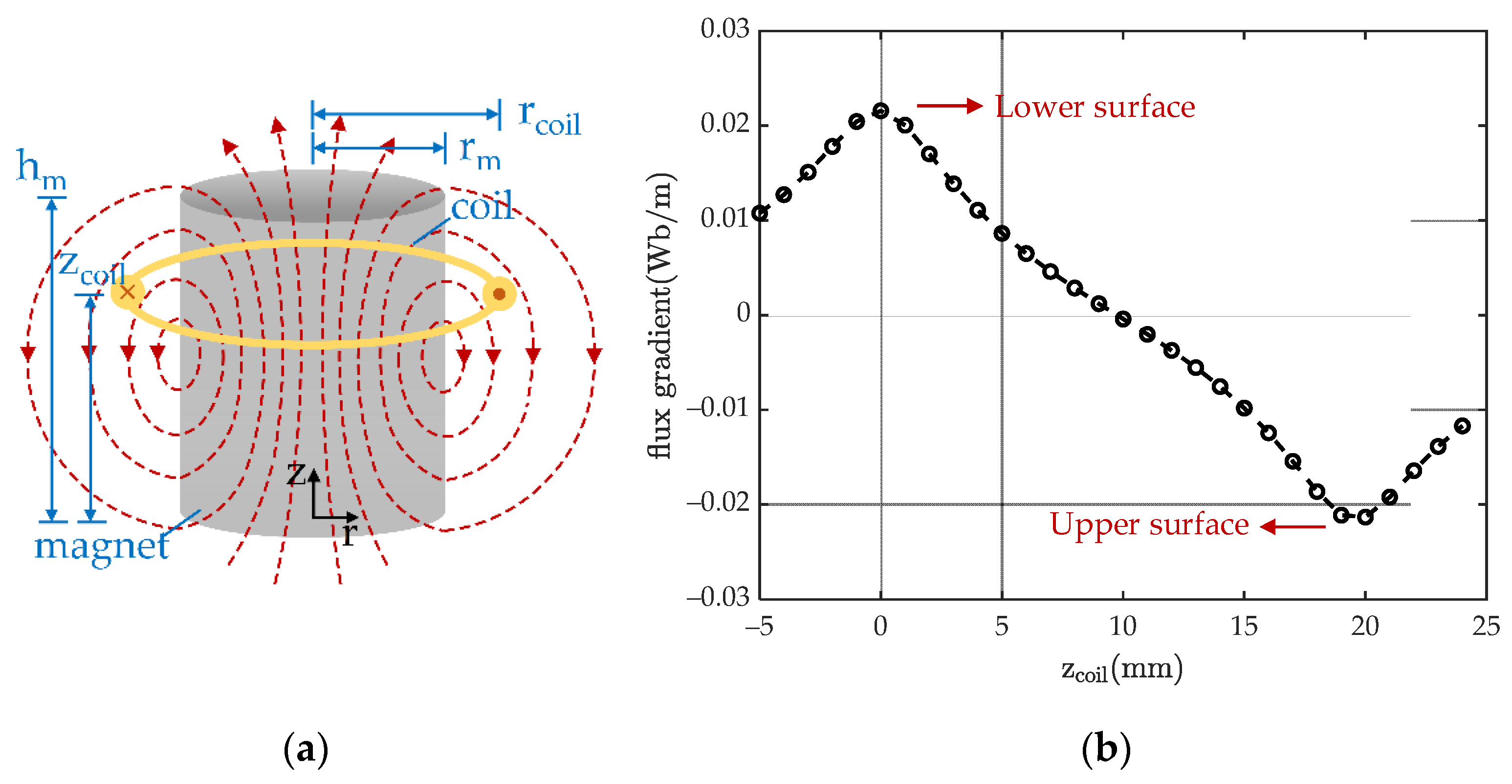
To induce high EMF voltage and power, coils should be placed in the position where the radial magnetic flux density is large to achieve high K e . The expression of K e for a single-turn coil is listed in Equation (16) [35], where rm and hm are magnet radius and height, respectively; r coil and z coil are the single-turn coil radius and the vertical position, respectively, as depicted in Figure 7a. The flux gradient of a single-turn coil with a radius of 12 mm at different positions is plotted in Figure 7b. A higher K e is obtained near the upper and lower surfaces of the permanent magnet. Therefore, a ring coil is located above the magnet with the key parameters listed in Table 1. The total flux gradient of the designed coil is 18.99 Wb/m.
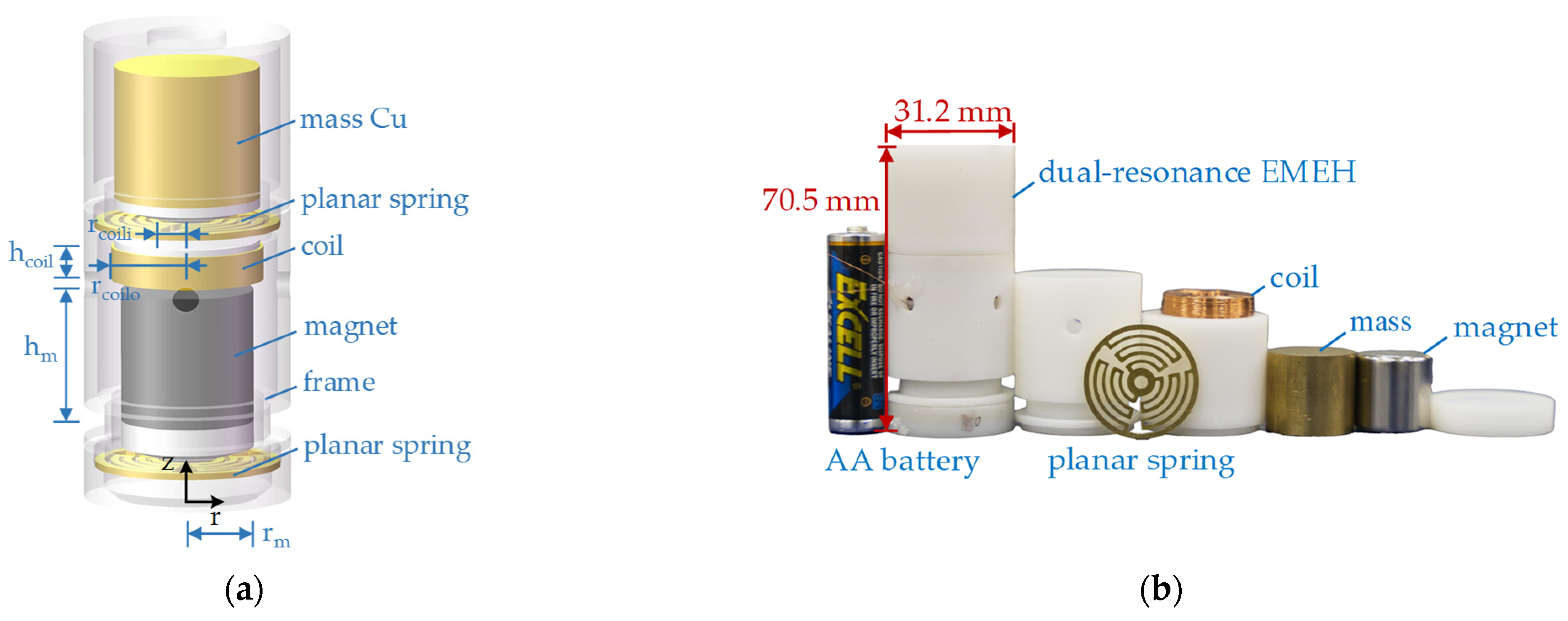
Figure 8a exhibits the three-dimensional assembly drawing of the designed dual resonance EMEH. The planar springs were processed by laser and the frames were processed by 3D printing. m1 was selected as a copper mass at 76 g. A NdFeB magnet of 46 g was adopted for m2. A tubular dual resonance EMEH was fabricated with a diameter of 31.2 mm and height of 70.5 mm, as shown in Figure 8b. It is worth pointing out that the copper mass 1 was selected just for manufacturing convenience. To further reduce the eddy current loss induced in the copper mass of m1, a non-magnetic and non-conductive material can be employed for future designs.
K e = 0 . 5 B r r m r coil 0 2 π [ cos θ r m 2 + r coil 2     2 r m r coil cos θ + ( h m     z coil ) 2     cos θ r m 2 + r coil 2     2 r m r coil cos θ + z coil 2 ] d θ .

4.2. Experimental Results and Discussion

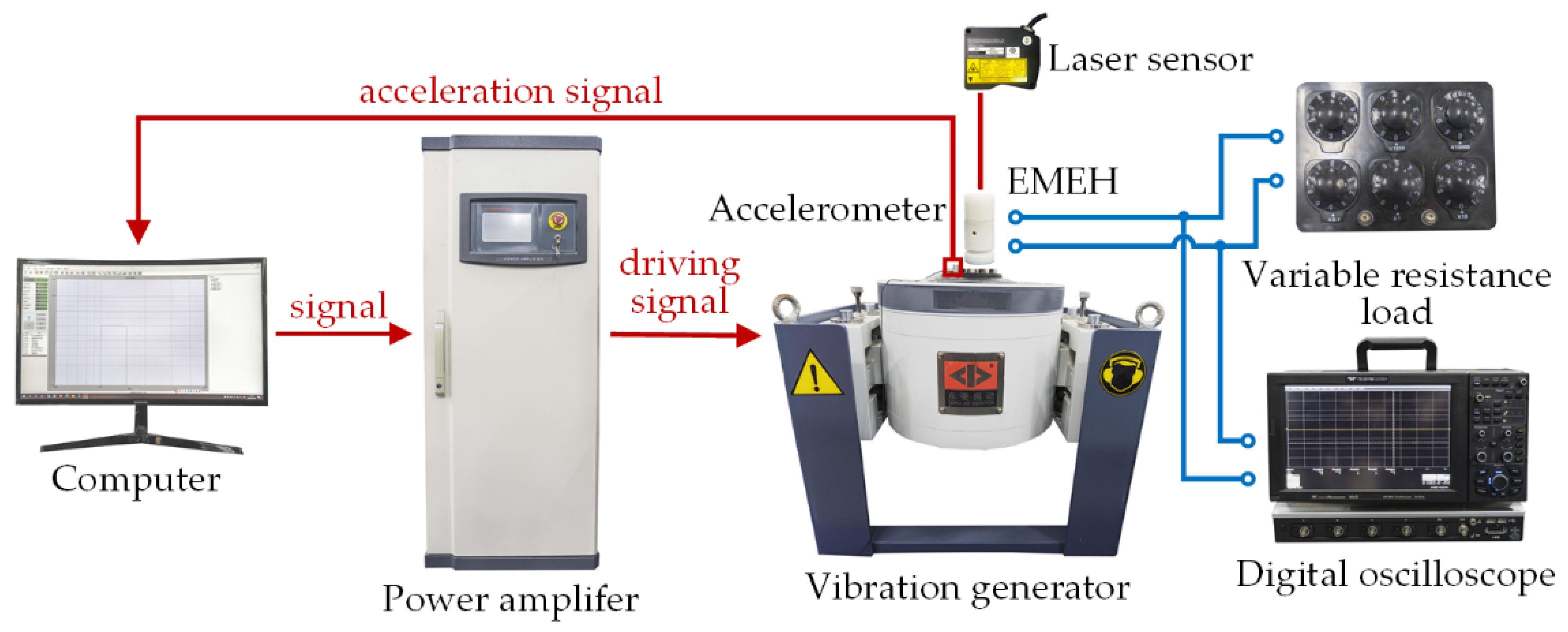
Figure 9 shows the electric vibration generation system ES-3-150 manufactured by Donglingtech (Suzhou, China), including a host computer, a power amplifier, and a vibration generator. A variable resistance box was used as the load of the EMEH, and the voltage signal was measured by a digital oscilloscope WaveRunner 604Zi manufactured by Teledyne LeCroy (New York, NY, USA). Panasonic’s (Osaka, Japan) laser position sensor HL-C235 was employed to measure the displacement of masses under no-load conditions to further extract the mechanical damping [36,37]. Under no load conditions, the EMEH can be treated as a traditional mass-spring-damper model and the transfer function | H 1 ( j ω ¯ vib ) | at the resonant frequency of ω n 1 would be simplified as | H 1 ( j ω ¯ vib ) | = 1 / 2 ξ 1 . By obtaining the maximum displacement through the laser position sensor, the mechanical damping of translator 1 is further calculated accordingly, as 0.22 N/(m/s) in this design, which is also the same as the mechanical damping of translator 2.
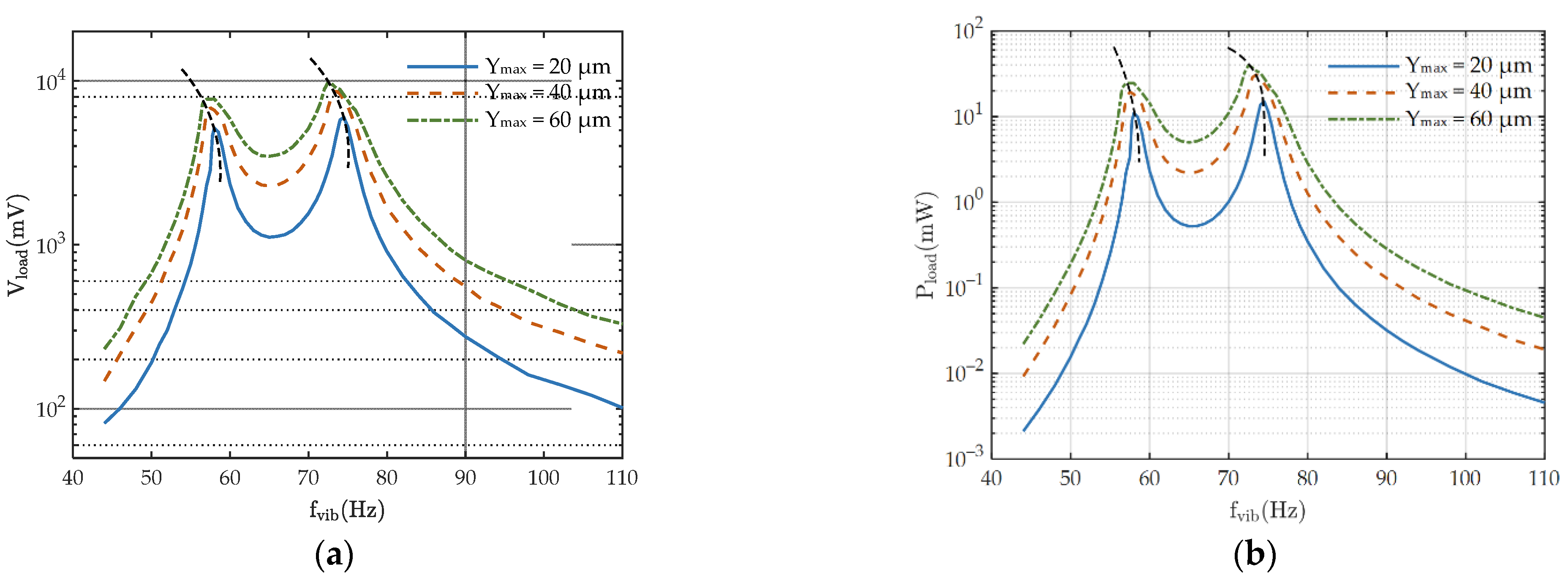
Figure 10a,b present output voltage and power of the designed dual resonance EMEH under different excitation amplitudes with a load resistor of 300 Ω. At the first resonance of 58 Hz, the output power under the excitation amplitudes of 20 μm, 40 μm, and 60 μm are 10.96 mW, 19.4 mW, and 24.6 mW, respectively. At the second resonance of 74.5 Hz, the output power under three excitation amplitudes is 14.9 mW, 32.4 mW, and 37.2 mW, respectively. At the excitation frequency of 65 Hz, the proposed EMEH has the lowest output power of 0.52 mW, 2.17 mW, and 4.99 mW under three excitation amplitudes, respectively. It is well known that output power is proportional to the square of the excitation amplitude at each excitation frequency [1,7,8]. However, this rule does not hold for dual resonance EMEH because that output power is saturated at two resonance frequencies, which is limited by the translators’ displacements. The parasitic damping is increased when the planar springs suffer from large deformations at two resonances [38]. When the excitation amplitude increases, two resonant frequencies of the EMEH are reduced slightly, especially for the second resonance, as shown in Figure 10a,b. Such phenomenon is caused by the nonlinear restoring force of the spring [15,16].
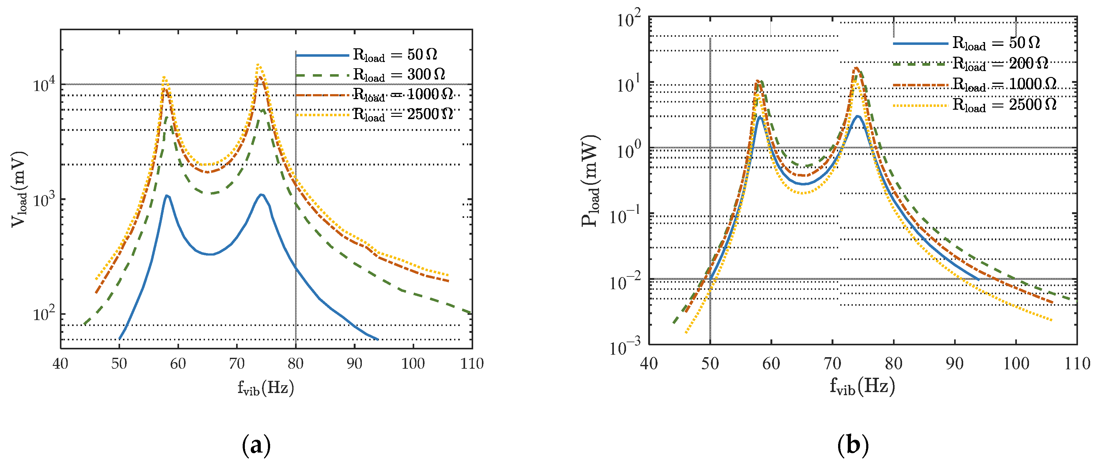
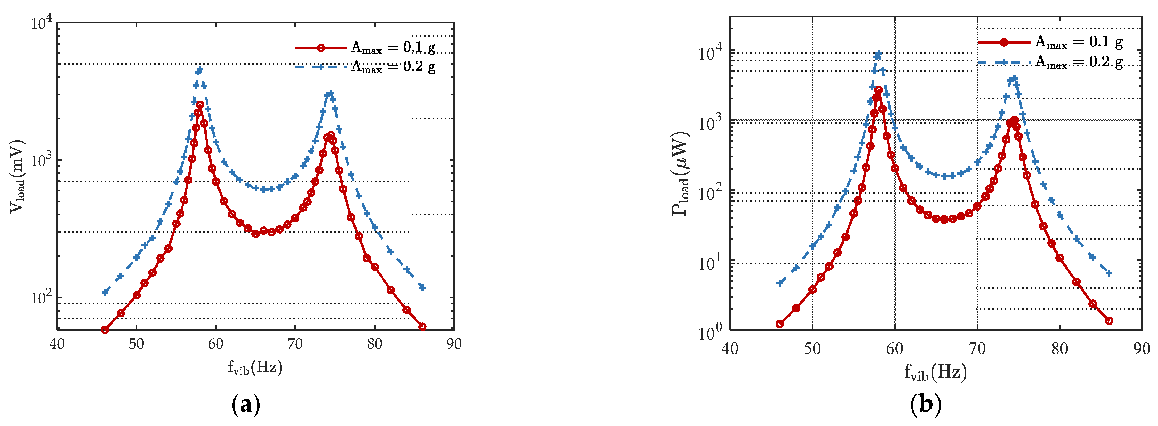
Figure 11a shows the output peak-to-peak voltage of the designed dual resonance EMEH under different loads with an excitation amplitude of 20 μm. Output voltage increases as the load increases. One reason for this is that the translators have larger displacements with the decrease of electromagnetic damping. The other reason is that larger load resistor has a larger output voltage due to the law of KVL. Figure 11b illustrates the relationship between output power and excitation frequency under different loads. The output power of the EMEH is lowest at the excitation frequency of 65 Hz, which is right in the middle of two resonances. Figure 12a shows the relationship between output power and loads resistors under the excitation frequency of 65 Hz. Hence, to improve output power between two resonant frequencies, a 300 Ω load is preferred for the proposed EMEH. The steady-state output voltage waveform is presented in Figure 12b with a vibration frequency and amplitude of 74.5 Hz and 20 μm, and a load resistance of 300 Ω. The output voltage is sinusoidal and the peak-to-peak voltage reaches 6.161 V. Acceleration follows a linear relationship with vibration amplitude, as A max = 4 π 2 f vib 2 Y max . Figure 13 further provides the harvested output voltage and power at different vibration frequencies, but with a constant maximum acceleration (Amax). The output characteristics follow the same trend as Figure 11.
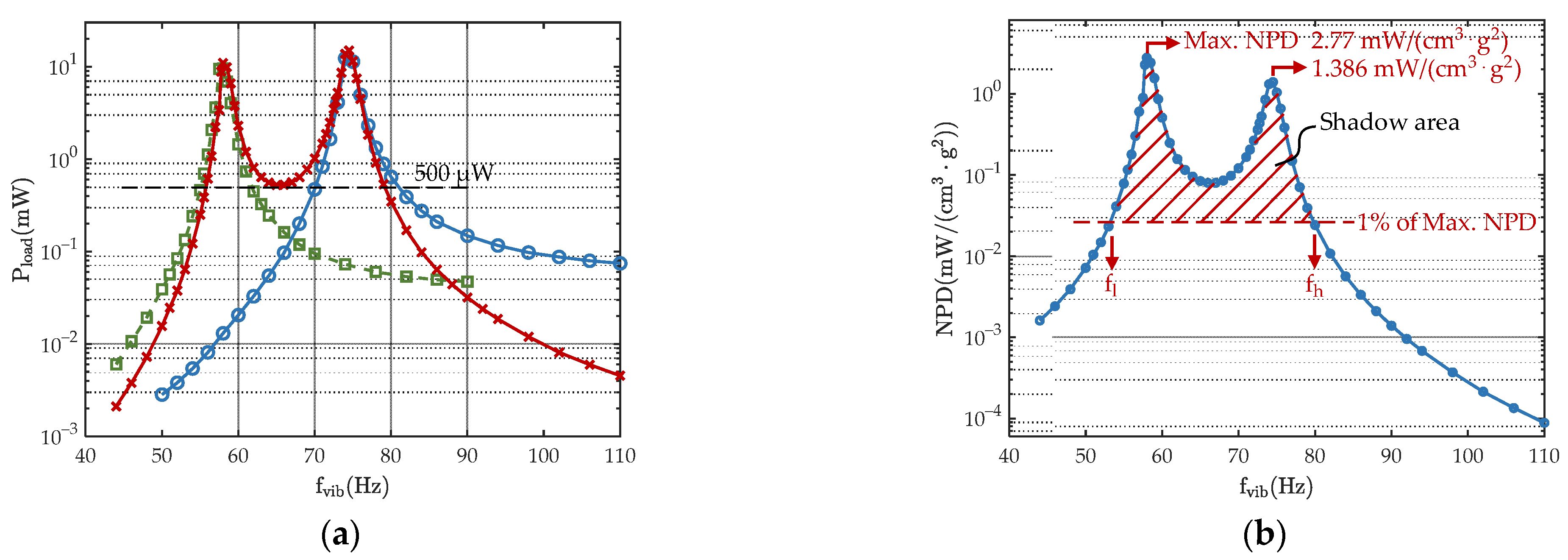
Two single resonance harvesters were designed and fabricated with the same design parameter at the resonant frequencies of 58 Hz and 74.5 Hz, respectively. Figure 14a shows output power of two single resonance EMEHs and the dual resonance EMEH under different excitation frequencies. The load is set as 300 Ω and the excitation amplitude is 20 μm. At the excitation frequency of 65 Hz, the dual resonance harvester reaches an output power of 523.8 μW. Two single resonance harvesters reach an output power of 72.9 μW and 200.5 μW, respectively. The dual resonance harvester achieves a higher output power than the summation of the two single resonance devices. In the dual resonance EMEH, the frequency range of the output power above 0.5 mW is from 55.8 Hz to 79.1 Hz. While for the single resonance EMEH with a resonance frequency 74.5 Hz, the frequency range of the output power above 0.5 mW is limited from 70.1 Hz to 80.1 Hz. The frequency range in the proposed dual resonance harvester is more than twice of that in single resonance harvester. Experiment results demonstrate the advantage of the dual resonance harvester of extending the frequency range and higher harvested power.
Since wideband EMEHs in the literature were designed under significant different specifications, the normalized power density (NPD) is proposed for a fair comparison [39], which is expressed in Equation (17). To further evaluate the covered frequency bandwidths among state-of-art apparatuses, index S, shown in Equation (18), is defined as the integral of the NPD higher than 1%, which represents the coverage area of the NPD higher than 1% of the maximum NPD in the frequency domain.
The designed EMEH has a maximum NPD of 2.77 mW/(cm3·g2) at the excitation frequency of 58 Hz and S of 10.53 mW/(s·cm3·g2) from frequency of 53.4 Hz to 79.7 Hz. Compared to the state-of-art EMEHs with wide frequency ranges in Table 2, the maximum NPD is high due to the adoption of a planar spring and the optimization of the coil position. Furthermore, the S parameter is more than 2× that of the state-of-art apparatuses. Hence, the proposed EMEH is demonstrated to have a high maximum NPD and high output power over wide harvesting frequencies.
NPD = P load ( 4 π 2 f vib 2 Y max / g ) 2 Volume
S = f l f h NPD ( f vib ) df vib

5. Conclusions

An electromagnetic energy harvester (EMEH) with dual resonant frequencies is proposed in this paper, which is constructed by two spring-mass resonators. Due to the angular differences between the two resonators, the relative displacement is increased within the frequency bandwidth to achieve enhanced output power. Compared with single resonance harvester with the same designed parameters, the proposed dual resonance EMEH achieves a 2.5 times larger frequency range. Furthermore, the two resonators are decoupled in the proposed configuration, so that the resonant frequencies of the proposed EMEH can be determined independently and are not cross-affected. Therefore, a high power “band-pass” EMEH can be achieved. A tubular dual spring-mass EHEM is designed with a diameter of 31.2 mm and height of 70.5 mm. Two resonant frequencies are designed at 58 Hz and 74.5 Hz. An output power of 14.9 mW is achieved at 74.5 Hz with a load of 300 Ω and an excitation amplitude of 20 μm. The frequency range of the output power above 0.5 mW is from 55.8 Hz to 79.1 Hz, reaching the width of 23 Hz. The maximum normalized power density (NPD) reaches to 2.77 mW/(cm3·g2), which is more than 2 times larger than state-of-art wideband EMEHs. The proposed dual resonance EMEH is verified to provide a descent high output power over “band-pass” frequency range. The proposed technology can be a promising technology when vibrations have wide frequency coverage.

Author Contributions

H.P. was the corresponding author and proposed the conceptual design of the device and supervised Z.F. and Y.C. for this work. Z.F. is responsible for the main technical work. Y.C. provided support for the design of the planar spring. All authors have read and agreed to the published version of the manuscript.

Funding

This research received no external funding.

Institutional Review Board Statement

Not applicable.

Informed Consent Statement

Informed consent was obtained from all subjects involved in the study.

Data Availability Statement

The data presented in this study are available on request from the corresponding author.

Conflicts of Interest

The authors declare no conflict of interests. The authors declare that they have no known competing financial interests or personal relationships that could have appeared to influence the work reported in this paper.

References

  1. Priya, S.; Inman, D.J. Energy Harvesting Technologies, 1st ed.; Springer US: Boston, MA, USA, 2008. [Google Scholar]
  2. Citroni, R.; Di Paolo, F.; Livreri, P. A Novel Energy Harvester for Powering Small UAVs: Performance Analysis, Model Validation and Flight Results. Sensors 2019, 19, 1771. [Google Scholar] [CrossRef] [Green Version]
  3. Citroni, R.; Di Paolo, F.; Livreri, P. Evaluation of an optical energy harvester for SHM application. AEU Int. J. Electron. Commun. 2019, 111, 152918. [Google Scholar] [CrossRef]
  4. Gu, Y.; Liu, W.; Zhao, C.; Wang, P. A goblet-like non-linear electromagnetic generator for planar multi-directional vibration energy harvesting. Appl. Energy 2020, 266, 114846. [Google Scholar] [CrossRef]
  5. Zhang, J.; Su, Y. Design and analysis of a non-resonant rotational electromagnetic harvester with alternating magnet sequence. J. Magn. Magn. Mater. 2021, 540, 168393. [Google Scholar] [CrossRef]
  6. Zhou, N.; Hou, Z.; Zhang, Y.; Cao, J.; Bowen, C.R. Enhanced swing electromagnetic energy harvesting from human motion. Energy 2021, 228, 120591. [Google Scholar] [CrossRef]
  7. Williams, C.B.; Shearwood, C.; Harradine, M.A.; Mellor, P.H.; Birch, T.S.; Yates, R.B. Development of an electromagnetic micro-generator. IEE P-Circ. Dev. Syst. 2001, 148, 337–342. [Google Scholar] [CrossRef]
  8. Stephen, N.G. On energy harvesting from ambient vibration. J. Sound Vib. 2006, 293, 409–425. [Google Scholar] [CrossRef] [Green Version]
  9. Chen, Y.; Peng, H.; Cheng, Z.; Tong, Q.; Kang, Y. A Planar PCB Based Energy Harvester with Voltage Multiplier. In Proceedings of the 2020 IEEE Energy Conversion Congress and Exposition (ECCE), Detroit, MI, USA, 11–15 October 2020; pp. 975–980. [Google Scholar]
  10. Makovička, D. Response Analysis of Building Loaded by Groundborne Transient Vibration. In Proceedings of the III European Conference on Computational Mechanics, Lisbon, Portugal, 5–8 June 2006; p. 748. [Google Scholar]
  11. Tang, L.; Yang, Y.; Soh, C.K. Toward Broadband Vibration-based Energy Harvesting. J. Intel. Mat. Syst. Str. 2010, 21, 1867–1897. [Google Scholar] [CrossRef]
  12. Foisal, A.R.M.; Hong, C.; Chung, G. Multi-frequency electromagnetic energy harvester using a magnetic spring cantilever. Sens. Actuators A Phys. 2012, 182, 106–113. [Google Scholar] [CrossRef]
  13. Ferrari, M.; Ferrari, V.; Guizzetti, M.; Marioli, D.; Taroni, A. Piezoelectric multifrequency energy converter for power harvesting in autonomous microsystems. Sens. Actuators A Phys. 2008, 142, 329–335. [Google Scholar] [CrossRef]
  14. Challa, V.R.; Prasad, M.G.; Fisher, F.T. Towards an autonomous self-tuning vibration energy harvesting device for wireless sensor network applications. Smart Mater. Struct. 2011, 20, 0250042. [Google Scholar] [CrossRef] [Green Version]
  15. Mann, B.P.; Sims, N.D. Energy harvesting from the nonlinear oscillations of magnetic levitation. J. Sound Vib. 2009, 319, 515–530. [Google Scholar] [CrossRef] [Green Version]
  16. Fan, K.; Cai, M.; Liu, H.; Zhang, Y. Capturing energy from ultra-low frequency vibrations and human motion through a monostable electromagnetic energy harvester. Energy 2019, 169, 356–368. [Google Scholar] [CrossRef]
  17. Palagummi, S.; Yuan, F.G. A bi-stable horizontal diamagnetic levitation based low frequency vibration energy harvester. Sens. Actuators A Phys. 2018, 279, 743–752. [Google Scholar] [CrossRef]
  18. Podder, P.; Amann, A.; Roy, S. Combined Effect of Bistability and Mechanical Impact on the Performance of a Nonlinear Electromagnetic Vibration Energy Harvester. IEEE-Asme T Mech. 2016, 21, 727–739. [Google Scholar] [CrossRef]
  19. Halim, M.A.; Cho, H.; Park, J.Y. Design and experiment of a human-limb driven, frequency up-converted electromagnetic energy harvester. Energy Convers. Manag. 2015, 106, 393–404. [Google Scholar] [CrossRef]
  20. Zorlu, O.; Topal, E.T.; Kulah, H. A Vibration-Based Electromagnetic Energy Harvester Using Mechanical Frequency Up-Conversion Method. IEEE Sens. J. 2011, 11, 481–488. [Google Scholar] [CrossRef]
  21. Wu, Z.; Cao, Z.; Ding, R.; Wang, S.; Chu, Y.; Ye, X. An electrostatic-electromagnetic hybrid generator with largely enhanced energy conversion efficiency. Nano Energy 2021, 89, 106425. [Google Scholar] [CrossRef]
  22. Wu, Y.; Zeng, Q.; Tang, Q.; Liu, W.; Liu, G.; Zhang, Y.; Wu, J.; Hu, C.; Wang, X. A teeterboard-like hybrid nanogenerator for efficient harvesting of low-frequency ocean wave energy. Nano Energy 2020, 67, 104205. [Google Scholar] [CrossRef]
  23. Li, P.; Gao, S.; Cai, H. Modeling and analysis of hybrid piezoelectric and electromagnetic energy harvesting from random vibrations. Microsyst. Technol. 2015, 21, 401–414. [Google Scholar] [CrossRef]
  24. Mahmoudi, S.; Kacem, N.; Bouhaddi, N. Enhancement of the performance of a hybrid nonlinear vibration energy harvester based on piezoelectric and electromagnetic transductions. Smart Mater. Struct. 2014, 23, 075024. [Google Scholar] [CrossRef]
  25. Iqbal, M.; Khan, F.U. Hybrid vibration and wind energy harvesting using combined piezoelectric and electromagnetic conversion for bridge health monitoring applications. Energy Convers. Manag. 2018, 172, 611–618. [Google Scholar] [CrossRef]
  26. Toyabur, R.M.; Salauddin, M.; Cho, H.; Park, J.Y. A multimodal hybrid energy harvester based on piezoelectric-electromagnetic mechanisms for low-frequency ambient vibrations. Energy Convers. Manag. 2018, 168, 454–466. [Google Scholar] [CrossRef]
  27. Tao, K.; Wu, J.; Tang, L.; Xia, X.; Lye, S.W.; Miao, J.; Hu, X. A novel two-degree-of-freedom MEMS electromagnetic vibration energy harvester. J. Micromech. Microeng. 2016, 26, 0350203. [Google Scholar] [CrossRef]
  28. Hu, G.; Tang, L.; Das, R.; Marzocca, P. A two-degree-of-freedom piezoelectric energy harvester with stoppers for achieving enhanced performance. Int. J. Mech. Sci. 2018, 149, 500–507. [Google Scholar] [CrossRef]
  29. Wang, H.; Tang, L. Modeling and experiment of bistable two-degree-of-freedom energy harvester with magnetic coupling. Mech. Syst. Signal. Process. 2017, 86, 29–39. [Google Scholar] [CrossRef]
  30. Wang, Z.; Ding, H.; Chen, L. Nonlinear oscillations of a two-degree-of-freedom energy harvester of magnetic levitation. J. Vib. Shock 2016, 35, 55–58. [Google Scholar]
  31. Cammarano, A.; Burrow, S.G.; Barton, D.A.W.; Carrella, A.; Clare, L.R. Tuning a resonant energy harvester using a generalized electrical load. Smart Mater. Struct. 2010, 19, 0550035. [Google Scholar] [CrossRef]
  32. Tang, L.; Yang, Y. A multiple-degree-of-freedom piezoelectric energy harvesting model. J. Intell. Mat. Syst. Struct. 2012, 23, 1631–1647. [Google Scholar] [CrossRef]
  33. Xiao, H.; Wang, X.; John, S. A dimensionless analysis of a 2DOF piezoelectric vibration energy harvester. Mech. Syst. Signal. Process. 2015, 58–59, 355–375. [Google Scholar] [CrossRef]
  34. Barillaro, G.; Molfese, A.; Nannini, A.; Pieri, F. Analysis, simulation and relative performances of two kinds of serpentine springs. J. Micromech. Microeng. 2005, 15, 736–746. [Google Scholar] [CrossRef]
  35. Cepnik, C.; Radler, O.; Rosenbaum, S.; Stroehla, T.; Wallrabe, U. Effective optimization of electromagnetic energy harvesters through direct computation of the electromagnetic coupling. Sens. Actuators A Phys. 2011, 167, 416–421. [Google Scholar] [CrossRef]
  36. Spreemann, D.; Manoli, Y. Electromagnetic Vibration Energy Harvesting Devices: Architectures, Design, Modeling and Optimization; Springer Science & Business Media: Dordrecht, The Netherlands, 2012; Volume 35. [Google Scholar]
  37. Dayal, R.; Dwari, S.; Parsa, L. A New Design for Vibration-Based Electromagnetic Energy Harvesting Systems Using Coil Inductance of Microgenerator. IEEE T Ind. Appl. 2011, 47, 820–830. [Google Scholar] [CrossRef]
  38. Wang, P. Study on the Micro Electromagnetic Vibration Energy Harvester Based on MEMS Technology. Ph.D. Thesis, Shanghai Jiao Tong University, Shanghai, China, 2010. [Google Scholar]
  39. Arnold, D.P. Review of microscale magnetic power generation. IEEE T Magn. 2007, 43, 3940–3951. [Google Scholar] [CrossRef]
  40. Fan, K.; Zhang, Y.; Liu, H.; Cai, M.; Tan, Q. A nonlinear two-degree-of-freedom electromagnetic energy harvester for ultra-low frequency vibrations and human body motions. Renew. Energy 2019, 138, 292–302. [Google Scholar] [CrossRef]
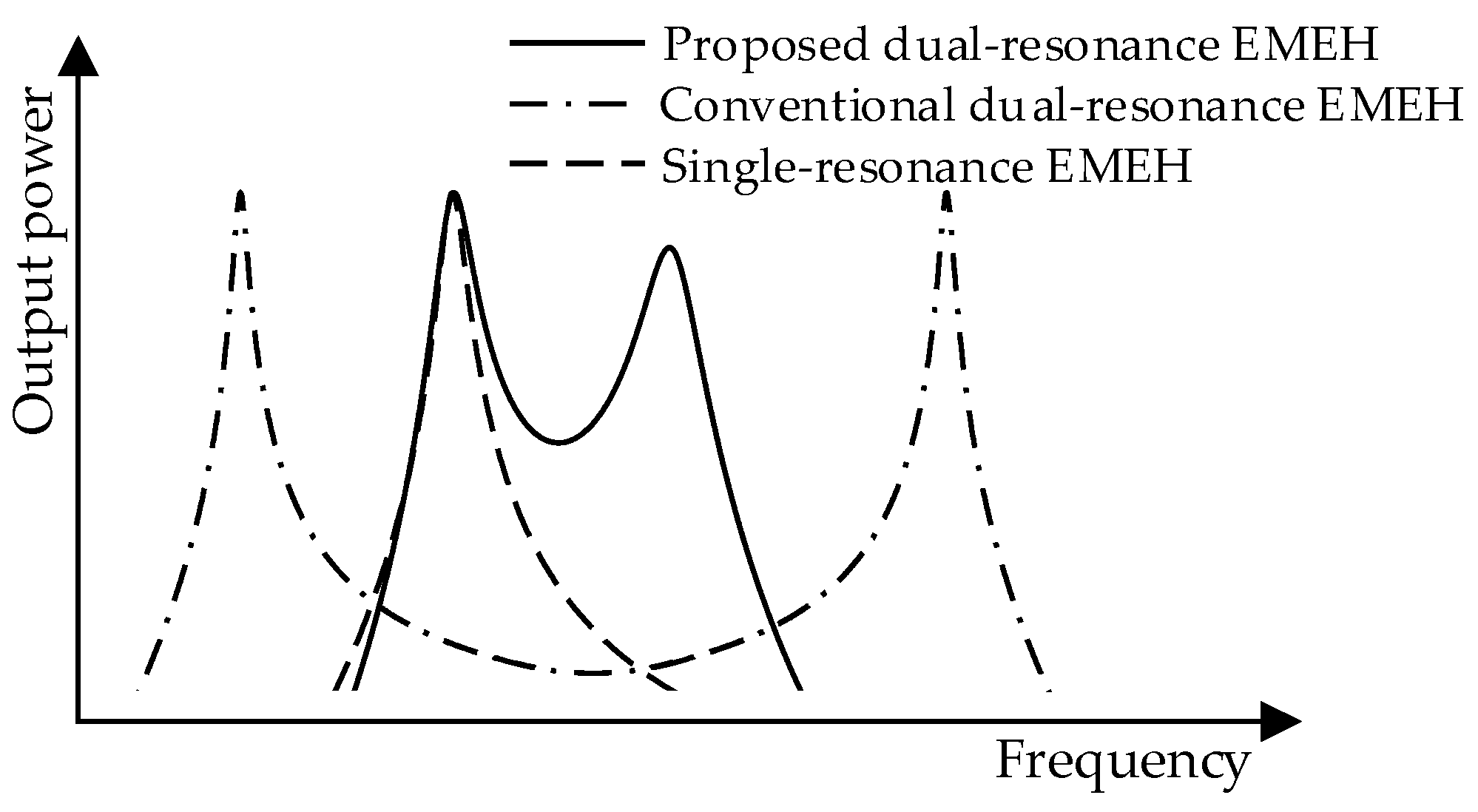
Figure 1. Comparison of the output power of a single resonance EMEH, conventional dual resonance EMEH, and the proposed dual resonance EMEH.
Energies 14 07675 g001
Figure 2. System topology of (a) the proposed dual resonance EMEH; and its (b) electrical equivalent circuit model.
Energies 14 07675 g002
Figure 3. (a) Frequency–domain characteristics of the proposed dual resonance EMEH; (b) Frequency-domain characteristics comparison of the single resonance EMEH and the proposed dual resonance EMEH.
Energies 14 07675 g003
Figure 4. The magnitude characteristic of the dimensionless transfer function for the proposed dual resonance EMEH under different α .
Energies 14 07675 g004
Figure 5. (a) The conventional dual resonance EMEH model. (b) The magnitude frequency characteristic of the normalized transfer functions for the conventional dual resonance EMEH under different μ at α = 1.2 . (c) The differences between the two resonant angular frequencies for the proposed and conventional dual resonance EMEHs vs. μ at different α and α . (d) The magnitude characteristic of the normalized transfer functions for the proposed and conventional dual resonance EMEHs at α = α = 1.2 and μ = 0.2 .
Energies 14 07675 g005
Figure 6. (a) Designed planar spring drawing. (b) Force reaction vs. displacement of the designed planar spring.
Energies 14 07675 g006
Figure 7. (a) Magnetic field distribution of the axial-magnetized cylindrical magnet. (b) Flux gradient of the single-turn coil vs. vertical position.
Energies 14 07675 g007
Figure 8. (a) 3D assembly drawing of the designed EMEH. (b) Prototype of the designed EMEH.
Energies 14 07675 g008
Figure 9. Testing bench of the vibration generation system.
Energies 14 07675 g009
Figure 10. (a) Output peal-to-peak voltage vs. vibration frequency under different sinusoidal excitations at Rload = 300 Ω. (b) Output power vs. vibration frequency under different excitation amplitudes at Rload = 300 Ω.
Energies 14 07675 g010
Figure 11. (a) Output peal-to-peak voltage vs. vibration frequency under different loads at Ymax = 20 μm. (b) Output peal-to-peak power vs. vibration frequency under different loads at Ymax = 20 μm.
Energies 14 07675 g011
Figure 12. (a) Output power vs. load under the excitation frequency of 65 Hz at Ymax = 20 μm. (b) Steady waveform of output voltage at fvib = 74.5 Hz, Ymax = 20 μm, and Rload = 300 Ω.
Energies 14 07675 g012
Figure 13. (a) Output peal-to-peak voltage vs. vibration frequency under two fixed excitation accelerations (Amax) at Rload = 300 Ω. (b) Output power vs. vibration frequency under two fixed excitation accelerations (Amax) at Rload = 300 Ω.
Energies 14 07675 g013
Figure 14. (a) Output power of two single resonance harvesters and the dual resonance EMEH vs. vibration frequency at Rload = 300 Ω, Ymax = 20 μm. (b) Normalized power density of the proposed dual resonance EMEH vs. vibration frequency at Rload = 300 Ω, Ymax = 20 μm.
Energies 14 07675 g014
Table 1. Key Design Parameters of the Proposed EMEH.
ParameterDescriptionValue
m1, m2Mass 1, Mass 276 g, 46 g
YmaxVibration source amplitude20, 40, 60 μm
RcoilInternal resistance of coil273 Ω
LcoilInternal inductance of coil77.8 mH
rmMagnet radius and height9.9 mm
hmMagnet height19.5 mm
BrRemanent magnetic flux density of magnet1.23 T
hcoilRing coil height5 mm
rcoiliRing coil inner radius5.2 mm
rcoiloRing coil outer radius11.5 mm
NcoilRing coil turns2350
θSpring sector angle100°
tsSpring thickness0.9 mm
wbSpring beam width1 mm
wgSpring beam gap width1 mm
rdSpring central disc radius3.5 mm
rsSpring outer radius14 mm
Table 2. Performance Comparisons Among State-of-art Apparatuses.
RefTransduction Type and Employed TechnologySpring TypeResonant Frequencies (Hz)Max. Output Power (mW)Volume (cm3)Max. NPD (mW/(cm3·g2))S (mW/(s·cm3·g2))
[40]Electromagnetic;
dual resonance, nonlinear
Magnetic spring7.5, 18.52.58 @ 7.5 Hz, 0.5 g9.73 1.065.2247
[27]Electromagnetic;
dual resonance
MEMS planar spring326, 3919.6 × 10−7 @ 391 Hz, 0.12 g0.292.3 × 10−4null
[12]Electromagnetic;
EH array
Magnetic spring7, 8, 9, 102.09 @ 8.5 Hz, 0.5 g40.180.208 @ 8.5 Hz, 0.5 g0.681
[18]Electromagnetic;
bi-stable EH
FR4 spring360.0193 @ 36 Hz, 1.5 g~1.171 7.325 × 10⁻³null
[19]Electromagnetic;
up-conversion
Helical springnull11.89 @ 5.17 Hz, 2.06 g6.470.07847null
[16]Electromagnetic;
nonlinear
Magnetic and helical springs91.15 @ 9 Hz, 0.8 g12.2 0.14730.7352
This
Work
Electromagnetic;
dual-resonance
Planar spring58, 74.539.8 @74.5 Hz, 0.45 g53.92.77 @ 58 Hz, 0.27 g10.53 @ 53.4–79.7 Hz
Publisher’s Note: MDPI stays neutral with regard to jurisdictional claims in published maps and institutional affiliations.